EP4126500B1 - Seal pin for container forming and filling head - Google Patents
Seal pin for container forming and filling head Download PDFInfo
- Publication number
- EP4126500B1 EP4126500B1 EP20933252.7A EP20933252A EP4126500B1 EP 4126500 B1 EP4126500 B1 EP 4126500B1 EP 20933252 A EP20933252 A EP 20933252A EP 4126500 B1 EP4126500 B1 EP 4126500B1
- Authority
- EP
- European Patent Office
- Prior art keywords
- product
- nozzle
- generating member
- container
- seal
- Prior art date
- Legal status (The legal status is an assumption and is not a legal conclusion. Google has not performed a legal analysis and makes no representation as to the accuracy of the status listed.)
- Active
Links
Images



Classifications
-
- B—PERFORMING OPERATIONS; TRANSPORTING
- B29—WORKING OF PLASTICS; WORKING OF SUBSTANCES IN A PLASTIC STATE IN GENERAL
- B29C—SHAPING OR JOINING OF PLASTICS; SHAPING OF MATERIAL IN A PLASTIC STATE, NOT OTHERWISE PROVIDED FOR; AFTER-TREATMENT OF THE SHAPED PRODUCTS, e.g. REPAIRING
- B29C49/00—Blow-moulding, i.e. blowing a preform or parison to a desired shape within a mould; Apparatus therefor
- B29C49/42—Component parts, details or accessories; Auxiliary operations
- B29C49/58—Blowing means
-
- B—PERFORMING OPERATIONS; TRANSPORTING
- B29—WORKING OF PLASTICS; WORKING OF SUBSTANCES IN A PLASTIC STATE IN GENERAL
- B29C—SHAPING OR JOINING OF PLASTICS; SHAPING OF MATERIAL IN A PLASTIC STATE, NOT OTHERWISE PROVIDED FOR; AFTER-TREATMENT OF THE SHAPED PRODUCTS, e.g. REPAIRING
- B29C49/00—Blow-moulding, i.e. blowing a preform or parison to a desired shape within a mould; Apparatus therefor
- B29C49/42—Component parts, details or accessories; Auxiliary operations
- B29C49/46—Component parts, details or accessories; Auxiliary operations characterised by using particular environment or blow fluids other than air
-
- B—PERFORMING OPERATIONS; TRANSPORTING
- B65—CONVEYING; PACKING; STORING; HANDLING THIN OR FILAMENTARY MATERIAL
- B65B—MACHINES, APPARATUS OR DEVICES FOR, OR METHODS OF, PACKAGING ARTICLES OR MATERIALS; UNPACKING
- B65B3/00—Packaging plastic material, semiliquids, liquids or mixed solids and liquids, in individual containers or receptacles, e.g. bags, sacks, boxes, cartons, cans, or jars
- B65B3/02—Machines characterised by the incorporation of means for making the containers or receptacles
- B65B3/022—Making containers by moulding of a thermoplastic material
-
- B—PERFORMING OPERATIONS; TRANSPORTING
- B65—CONVEYING; PACKING; STORING; HANDLING THIN OR FILAMENTARY MATERIAL
- B65B—MACHINES, APPARATUS OR DEVICES FOR, OR METHODS OF, PACKAGING ARTICLES OR MATERIALS; UNPACKING
- B65B3/00—Packaging plastic material, semiliquids, liquids or mixed solids and liquids, in individual containers or receptacles, e.g. bags, sacks, boxes, cartons, cans, or jars
- B65B3/04—Methods of, or means for, filling the material into the containers or receptacles
-
- B—PERFORMING OPERATIONS; TRANSPORTING
- B29—WORKING OF PLASTICS; WORKING OF SUBSTANCES IN A PLASTIC STATE IN GENERAL
- B29C—SHAPING OR JOINING OF PLASTICS; SHAPING OF MATERIAL IN A PLASTIC STATE, NOT OTHERWISE PROVIDED FOR; AFTER-TREATMENT OF THE SHAPED PRODUCTS, e.g. REPAIRING
- B29C49/00—Blow-moulding, i.e. blowing a preform or parison to a desired shape within a mould; Apparatus therefor
- B29C49/42—Component parts, details or accessories; Auxiliary operations
- B29C49/46—Component parts, details or accessories; Auxiliary operations characterised by using particular environment or blow fluids other than air
- B29C2049/4602—Blowing fluids
- B29C2049/465—Blowing fluids being incompressible
- B29C2049/4664—Blowing fluids being incompressible staying in the final article
-
- B—PERFORMING OPERATIONS; TRANSPORTING
- B29—WORKING OF PLASTICS; WORKING OF SUBSTANCES IN A PLASTIC STATE IN GENERAL
- B29L—INDEXING SCHEME ASSOCIATED WITH SUBCLASS B29C, RELATING TO PARTICULAR ARTICLES
- B29L2031/00—Other particular articles
- B29L2031/712—Containers; Packaging elements or accessories, Packages
Definitions
- the present disclosure relates to a seal pin assembly for a forming and filling head configured to inject a product into a thermoplastic preform for simultaneously forming a container from the thermoplastic preform and filling the container with the product.
- Seal pin assemblies according to the prior art are described in Patent documents US2019/016037A1 , US2013/074979A1 , US2016/107367A1 and US2017/291345A1 .
- Polymeric containers are used to store various types of food and beverages. Such containers are typically formed from a preform using various processes. One such process involves simultaneously forming the container from a preform and filling the container with any suitable product. This process is commonly referred to as Liquiform ® . To simultaneously form and fill the container, a forming/filling head is placed into cooperation with a finish of the preform.
- Liquiform ® heads While current Liquiform ® heads are suitable for their intended use, they are subject to improvement. For example, flow through existing heads may become "sided" (i.e., non-conical), depending on how the liquid enters the head and how flow drags around the stretch rod. When forming high-density polyethylene containers, gates have been seen to drift off-center to a repeatable container side (with respect to the mold). Also, with existing Liquiform ® heads excessive material bubbling may occur during forming/filling, and shoulder areas of the container may not properly form. The present disclosure advantageously provides for an improved seal pin assembly that address these issues. One skilled in the art will appreciate that the present disclosure provides numerous additional advantages and unexpected results as well.
- the present disclosure includes a seal pin assembly for a forming and filling head configured to inject a product into a thermoplastic preform for simultaneously forming a container from the thermoplastic preform and filling the container with the product.
- the seal pin assembly includes a seal pin movable within the forming and filling head towards and away from a nozzle of the forming and filling head.
- the nozzle is configured to cooperate with the thermoplastic preform.
- a vortex generating member is mounted to the seal pin and configured to convert a stream of the product into a vortex as the product flows across the vortex generating member and out through the nozzle.
- the present disclosure further includes a method for simultaneously forming a container from a thermoplastic preform and filling the container with a product dispersed from a nozzle of a forming and filling head including a seal pin assembly.
- the method includes converting a stream of the product into a vortex by directing the stream of the product across a vortex generating member mounted to a seal pin of the seal pin assembly such that the product exits the nozzle and flows into the preform as a uniform, conical stream having a centrifugal motion.
- FIGS. 1 and 2 illustrate a seal pin assembly 10 in accordance with the present disclosure for use with any suitable machine head, such as forming and filling head 12 for simultaneously forming and filling a polymeric container from a container preform 210.
- the preform 210 and the resulting container can be formed of any suitable polymeric material, such as polyethylene terephthalate (PET), low-density polyethylene (LDPE), high-density polyethylene (HDPE), polypropylene (PP), polystyrene, and the like, for example.
- PET polyethylene terephthalate
- LDPE low-density polyethylene
- HDPE high-density polyethylene
- PP polypropylene
- polystyrene polystyrene
- the forming and filling head 12 is configured for use with any suitable Liquiform ® machine, for example, such as described in the following United States Patents 7,914,726 ; 8,017,064 ; 8,435,026 ; and 8,573,964 .
- a nozzle 14 is secured to an outlet 16 of the forming and filling head 12 in any suitable manner, such as with a coupling member 20.
- any suitable product can be injected from the head 12 into the preform 210 by way of the nozzle 14 to simultaneously form a container from the preform 210 and fill the container with the product.
- Suitable products include, but are not limited to, water, sports drinks, juice, sauces, any suitable foodstuffs, etc.
- the seal pin assembly 10 generally includes a seal pin 30, which is moveable within the forming and filling head 12 to open and close the nozzle 14. In a closed position, a seal 32 of the seal pin assembly 10 contacts and seals against a nozzle seal 34 of the nozzle to prevent product from exiting the nozzle 14. In an open position, the seal 32 is spaced apart from the nozzle seal 34 to allow fluid to flow through the nozzle 14 and into the preform 210. To facilitate forming of the container, a stretch rod 36 may be extended through the seal 32 and the nozzle 14, and into the preform 210.
- the seal pin assembly 10 further includes a vortex generating member 50, which may be coupled to a distal end of the seal pin 30.
- the seal 32 is coupled to the vortex generating member 50.
- the vortex generating member 50 generally includes a proximal end 52 and a distal end 54, which is opposite to the proximal end 52.
- an upper coupling 56 At the proximal end 52 is an upper coupling 56, which may include any suitable coupling members configured to couple with the seal pin 30.
- the upper coupling 56 includes threads configured to cooperate with threads at a distal end of the seal pin 30.
- a lower coupling 58 At the distal end 54 of the vortex generating member 50 is a lower coupling 58, which may be configured in any suitable manner to connect the seal 32 to the distal end 54.
- the lower coupling 58 includes a plurality of threads configured to cooperate with threads of the seal 32.
- the vortex generating member 50 defines a bore 60 extending through the vortex generating member 50 along an axis A thereof extending from the proximal end 52 to the distal end 54.
- the bore 60 is sized and shaped to accommodate the stretch rod 36.
- the vortex generating member 50 further includes a body 70 between the upper coupling 56 and the lower coupling 58.
- the body 70 includes a plurality of vanes extending from an outer periphery of the body 70 away from the axis A.
- the vanes 72 define channels 74. Specifically, each one of the channels 74 is defined between vanes 72 that are directly adjacent to one another.
- the vanes 72 extend in a helical manner, and the channels 74 are helical channels.
- the vanes 72 extend outward to an inner surface of the nozzle 14 such that the vanes 72 abut, or nearly abut, the inner surface of the nozzle 14.
- the centrifugal motion of the product advantageously generates a density gradient where bubbles of the product move towards a center of the container after the container has been formed from the preform 210.
- the bubbles coalesce, rise to a surface of the product, and disperse.
- a container formed and filled with product that has flowed through the channels 74 of the vortex generating member 50 will have fewer bubbles as compared to product filled with a filling head that does not include the vortex generating member 50.
- the bubbles quickly rise to the surface and disperse because, in part, there is little or no contact/adherence to a sidewall of the container and no isolation in suspension of the bubbles.
- the vortex/centrifugal flow of product within the formed container continues for about 15-20 seconds post-formation of the container, at least with respect to products having a viscosity similar to water.
- the bubbles move from the sidewall of the container to the center of the container due to centrifugal forces creating a density gradient.
- the bubbles combine and rise to the surface of the product as a single mass.
- duration of the bubbles is less as compared to containers that are filled with filling heads that do not include the vortex generating member 50.
- an aneurism often forms close to a gate, and a shoulder of the container is the last portion to form.
- product that has passed through the helical channels 74 of the vortex generating member 50 is directed in the "hoop" direction after the product flows out of the nozzle 14 and into the preform 210.
- the aneurism is closer to the shoulder of the container, which results in improved formation of the shoulder as compared to containers that are formed/filled with filling heads that do not include the vortex generating member 50.
Landscapes
- Engineering & Computer Science (AREA)
- Mechanical Engineering (AREA)
- Manufacturing & Machinery (AREA)
- Blow-Moulding Or Thermoforming Of Plastics Or The Like (AREA)
- Processing And Handling Of Plastics And Other Materials For Molding In General (AREA)
Description
- The present disclosure relates to a seal pin assembly for a forming and filling head configured to inject a product into a thermoplastic preform for simultaneously forming a container from the thermoplastic preform and filling the container with the product. Seal pin assemblies according to the prior art are described in Patent documents
US2019/016037A1 ,US2013/074979A1 ,US2016/107367A1 andUS2017/291345A1 . - This section provides background information related to the present disclosure, which is not necessarily prior art.
- Polymeric containers are used to store various types of food and beverages. Such containers are typically formed from a preform using various processes. One such process involves simultaneously forming the container from a preform and filling the container with any suitable product. This process is commonly referred to as Liquiform®. To simultaneously form and fill the container, a forming/filling head is placed into cooperation with a finish of the preform.
- While current Liquiform® heads are suitable for their intended use, they are subject to improvement. For example, flow through existing heads may become "sided" (i.e., non-conical), depending on how the liquid enters the head and how flow drags around the stretch rod. When forming high-density polyethylene containers, gates have been seen to drift off-center to a repeatable container side (with respect to the mold). Also, with existing Liquiform® heads excessive material bubbling may occur during forming/filling, and shoulder areas of the container may not properly form. The present disclosure advantageously provides for an improved seal pin assembly that address these issues. One skilled in the art will appreciate that the present disclosure provides numerous additional advantages and unexpected results as well.
- This section provides a general summary of the disclosure, and is not a comprehensive disclosure of its full scope or all of its features.
- The present disclosure includes a seal pin assembly for a forming and filling head configured to inject a product into a thermoplastic preform for simultaneously forming a container from the thermoplastic preform and filling the container with the product. The seal pin assembly includes a seal pin movable within the forming and filling head towards and away from a nozzle of the forming and filling head. The nozzle is configured to cooperate with the thermoplastic preform. A vortex generating member is mounted to the seal pin and configured to convert a stream of the product into a vortex as the product flows across the vortex generating member and out through the nozzle.
- The present disclosure further includes a method for simultaneously forming a container from a thermoplastic preform and filling the container with a product dispersed from a nozzle of a forming and filling head including a seal pin assembly. The method includes converting a stream of the product into a vortex by directing the stream of the product across a vortex generating member mounted to a seal pin of the seal pin assembly such that the product exits the nozzle and flows into the preform as a uniform, conical stream having a centrifugal motion.
- Further areas of applicability will become apparent from the description provided herein. The description and specific examples in this summary are intended for purposes of illustration only and are not intended to limit the scope of the present disclosure.
- The drawings described herein are for illustrative purposes only of select embodiments and not all possible implementations, and are not intended to limit the scope of the present disclosure.
-
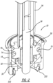
FIG. 1 is a cross-sectional view of seal pin assembly in accordance with the present disclosure including in a forming/filling head configured to inject product into a preform to simultaneously form a container from the preform and fill the container with the product; -
FIG. 2 is a perspective view ofFIG. 1 ; -
FIG. 3A is a side view of a vortex generating member in accordance with the present disclosure configured to convert a stream of the product into a vortex as the product flows across the vortex generating member; -
FIG. 3B is a perspective view of the vortex generating member ofFIG. 3A ; and -
FIG. 3C is a top view of the vortex generating member ofFIG. 3A . - Corresponding reference numerals indicate corresponding parts throughout the several views of the drawings.
- Example embodiments will now be described more fully with reference to the accompanying drawings.
-
FIGS. 1 and2 illustrate aseal pin assembly 10 in accordance with the present disclosure for use with any suitable machine head, such as forming and fillinghead 12 for simultaneously forming and filling a polymeric container from a container preform 210. Thepreform 210 and the resulting container can be formed of any suitable polymeric material, such as polyethylene terephthalate (PET), low-density polyethylene (LDPE), high-density polyethylene (HDPE), polypropylene (PP), polystyrene, and the like, for example. The forming and fillinghead 12 is configured for use with any suitable Liquiform® machine, for example, such as described in the followingUnited States Patents 7,914,726 ;8,017,064 ;8,435,026 ; and8,573,964 . - A
nozzle 14 is secured to anoutlet 16 of the forming and fillinghead 12 in any suitable manner, such as with acoupling member 20. With thenozzle 14 secured to thehead 12, and afinish 212 of thepreform 210 sealed to thenozzle 14, any suitable product can be injected from thehead 12 into thepreform 210 by way of thenozzle 14 to simultaneously form a container from thepreform 210 and fill the container with the product. Suitable products include, but are not limited to, water, sports drinks, juice, sauces, any suitable foodstuffs, etc. - The
seal pin assembly 10 generally includes aseal pin 30, which is moveable within the forming and fillinghead 12 to open and close thenozzle 14. In a closed position, aseal 32 of theseal pin assembly 10 contacts and seals against anozzle seal 34 of the nozzle to prevent product from exiting thenozzle 14. In an open position, theseal 32 is spaced apart from thenozzle seal 34 to allow fluid to flow through thenozzle 14 and into thepreform 210. To facilitate forming of the container, astretch rod 36 may be extended through theseal 32 and thenozzle 14, and into thepreform 210. - With continued reference to
FIGS. 1 and2 , and additional reference toFIGS. 3A, 3B , and3C , theseal pin assembly 10 further includes avortex generating member 50, which may be coupled to a distal end of theseal pin 30. Theseal 32 is coupled to thevortex generating member 50. Thevortex generating member 50 generally includes aproximal end 52 and adistal end 54, which is opposite to theproximal end 52. At theproximal end 52 is anupper coupling 56, which may include any suitable coupling members configured to couple with theseal pin 30. In the example illustrated, theupper coupling 56 includes threads configured to cooperate with threads at a distal end of theseal pin 30. At thedistal end 54 of thevortex generating member 50 is alower coupling 58, which may be configured in any suitable manner to connect theseal 32 to thedistal end 54. In the example illustrated, thelower coupling 58 includes a plurality of threads configured to cooperate with threads of theseal 32. Thevortex generating member 50 defines abore 60 extending through thevortex generating member 50 along an axis A thereof extending from theproximal end 52 to thedistal end 54. Thebore 60 is sized and shaped to accommodate thestretch rod 36. - The
vortex generating member 50 further includes abody 70 between theupper coupling 56 and thelower coupling 58. Thebody 70 includes a plurality of vanes extending from an outer periphery of thebody 70 away from the axis A. Thevanes 72 definechannels 74. Specifically, each one of thechannels 74 is defined betweenvanes 72 that are directly adjacent to one another. Thevanes 72 extend in a helical manner, and thechannels 74 are helical channels. Thevanes 72 extend outward to an inner surface of thenozzle 14 such that thevanes 72 abut, or nearly abut, the inner surface of thenozzle 14. - Product flowing through the filling
head 12 and thenozzle 14 flows through thechannels 74. Because thechannels 74 are helical, a stream of the product is converted from a generally linearly flow into a vortex. As a result, the product exits thenozzle 14 as a uniform, conical stream having a centrifugal motion. - The centrifugal motion of the product advantageously generates a density gradient where bubbles of the product move towards a center of the container after the container has been formed from the
preform 210. The bubbles coalesce, rise to a surface of the product, and disperse. As a result, a container formed and filled with product that has flowed through thechannels 74 of thevortex generating member 50 will have fewer bubbles as compared to product filled with a filling head that does not include thevortex generating member 50. The bubbles quickly rise to the surface and disperse because, in part, there is little or no contact/adherence to a sidewall of the container and no isolation in suspension of the bubbles. - The vortex/centrifugal flow of product within the formed container continues for about 15-20 seconds post-formation of the container, at least with respect to products having a viscosity similar to water. During this time, the bubbles move from the sidewall of the container to the center of the container due to centrifugal forces creating a density gradient. As the vortex flow slows, the bubbles combine and rise to the surface of the product as a single mass. As a result, duration of the bubbles is less as compared to containers that are filled with filling heads that do not include the
vortex generating member 50. - With respect to filling heads that do not include the
vortex generating member 50, an aneurism often forms close to a gate, and a shoulder of the container is the last portion to form. In contrast, product that has passed through thehelical channels 74 of thevortex generating member 50 is directed in the "hoop" direction after the product flows out of thenozzle 14 and into thepreform 210. As a result, the aneurism is closer to the shoulder of the container, which results in improved formation of the shoulder as compared to containers that are formed/filled with filling heads that do not include thevortex generating member 50. - The foregoing description of the embodiments has been provided for purposes of illustration and description. It is not intended to be exhaustive or to limit the disclosure. Individual elements or features of a particular embodiment are generally not limited to that particular embodiment, but, where applicable, are interchangeable and can be used in a selected embodiment, even if not specifically shown or described. The same may also be varied in many ways. Such variations are not to be regarded as a departure from the disclosure, and all such modifications are intended to be included within the scope of the disclosure as defined in the appended claims.
Claims (13)
- A seal pin assembly (10) for a forming and filling head (12) configured to inject a product into a thermoplastic preform (210) for simultaneously forming a container from the thermoplastic preform (210) and filling the container with the product, the seal pin assembly (10) comprising:a seal pin (30) movable within the forming and filling head (12) towards and away from a nozzle (14) of the forming and filling head (12), the nozzle (14) configured to cooperate with the thermoplastic preform (210); anda vortex generating member (50) comprising a proximal end (52) and a distal end (54), which is opposite to the proximal end (52), wherein the vortex generating member (50) is coupled to the seal pin (30) at the proximal end (52) and configured to convert a stream of the product into a vortex as the product flows across the vortex generating member (50) and out through the nozzle (14), the vortex generating member (50) defining a bore (60) extending through the vortex generating member (50) along an axis (A) thereof extending from the proximal end (52) to the distal end (54), wherein the bore (6) is sized and shaped to accommodate a stretch rod (36) therein; andthe seal pin assembly further comprises a seal (32) coupled to the vortex generating member (50) at the distal end (54) of the vortex generating member (50), the seal (32) configured to seal against the nozzle (14).
- The seal pin assembly (10) of claim 1,
characterized in that
the vortex generating member (50) includes threads configured to cooperate with the seal pin (30) to connect the vortex generating member (50) to the seal pin (30). - The seal pin assembly (10) of claim 1 or 2,
characterized in that
the vortex generating member (50) includes a plurality of vanes (72) extending about an outer surface of the vortex generating member (50),
wherein preferably the plurality of vanes (72) define channels (74) therebetween through which the product flows. - The seal pin assembly (10) of claim 3,
characterized in that
the plurality of vanes (72) and the plurality of channels (74) are helical,
wherein preferably the plurality of channels (74) are configured such that product that flows through the plurality of channels (74) exits the nozzle (14) as a uniform, conical stream. - The seal pin assembly (10) of claim 4,
characterized in that
the plurality of channels (74) are configured such that product that flows through the plurality of channels (74) exits the nozzle (14) with a centrifugal motion. - The seal pin assembly of claim 5,
characterized in that
the plurality of channels (74) are configured such that as the product exits the nozzle (14) and flows into the container, centrifugal motion of the product generates a density gradient where bubbles of the product move towards a center of the container after the container has been formed from the preform (210), the bubbles coalesce, rise to a surface of the product, and disperse. - The seal pin assembly (10) of claim 5 or 6,
characterized in that
the plurality of channels (74) are configured such that as the product exits the nozzle (14) and flows into the container, an aneurism forms at a shoulder of the container. - A method for simultaneously forming a container from a thermoplastic preform (210) and filling the container with a product dispersed from a nozzle (14) of a forming and filling head (12) including a seal pin assembly (10) of one of the preceding claims, the method comprising:
converting a stream of the product into a vortex by directing the stream of the product across the vortex generating member (50) mounted to the seal pin (30) of the seal pin assembly (10) such that the product exits the nozzle (14) and flows into the preform (210) as a uniform, conical stream having a centrifugal motion. - The method of claim 8,
characterized in that
the product is directed through helical channels (74) of the vortex generating member (50) defined by helical vanes (72) of the vortex generating member (50). - The method of claim 8 or 9,
characterized in that
the method further comprises moving the stretch rod (36) through the bore (60) defined by the vortex generating member (50). - The method of one of claims 8 to 10,
characterized in that
the method further comprises moving the seal (32) of the seal pin assembly (10) into cooperation with a nozzle seal (34) of the nozzle (14) to prevent product from flowing out of the nozzle (14), and moving the seal (32) out of cooperation with the nozzle seal (34) to allow product to flow out of the nozzle (14) and into the preform (210). - The method of one of claims 8 to 11,
characterized in that
the method further comprises using the centrifugal motion of the product to generate a density gradient where bubbles of the product move towards a center of the container after the container has been formed from the preform (210), the bubbles coalesce, rise to a surface of the product, and disperse. - The method of one of claims 8 to 12,
characterized in that
the method further comprises forming an aneurism at a shoulder of the container.
Applications Claiming Priority (1)
| Application Number | Priority Date | Filing Date | Title |
|---|---|---|---|
| PCT/US2020/030439 WO2021221628A1 (en) | 2020-04-29 | 2020-04-29 | Seal pin for container forming and filling head |
Publications (3)
| Publication Number | Publication Date |
|---|---|
| EP4126500A1 EP4126500A1 (en) | 2023-02-08 |
| EP4126500A4 EP4126500A4 (en) | 2023-11-29 |
| EP4126500B1 true EP4126500B1 (en) | 2024-12-11 |
Family
ID=78373803
Family Applications (1)
| Application Number | Title | Priority Date | Filing Date |
|---|---|---|---|
| EP20933252.7A Active EP4126500B1 (en) | 2020-04-29 | 2020-04-29 | Seal pin for container forming and filling head |
Country Status (5)
| Country | Link |
|---|---|
| US (1) | US20230182368A1 (en) |
| EP (1) | EP4126500B1 (en) |
| CA (1) | CA3176960A1 (en) |
| MX (1) | MX2022013571A (en) |
| WO (1) | WO2021221628A1 (en) |
Family Cites Families (11)
| Publication number | Priority date | Publication date | Assignee | Title |
|---|---|---|---|---|
| DE102008050697A1 (en) * | 2008-10-07 | 2010-04-08 | Krones Ag | Quick-change tuyere |
| DE102010022875A1 (en) * | 2010-06-07 | 2011-12-08 | Khs Gmbh | Filling element and filling machine for filling bottles or similar containers |
| US8714964B2 (en) * | 2010-10-15 | 2014-05-06 | Amcor Limited | Blow nozzle to control liquid flow with pre-stretch rod assembly |
| WO2013058351A1 (en) * | 2011-10-21 | 2013-04-25 | 株式会社村田製作所 | Multilayer wiring substrate, probe card, and method for manufacturing multilayer wiring substrate |
| US9254617B2 (en) * | 2011-10-27 | 2016-02-09 | Discma Ag | Method and apparatus for forming and filling a container |
| US8827688B2 (en) * | 2011-12-21 | 2014-09-09 | Amcor Limited | Sealing system for molding machine |
| US9366315B2 (en) * | 2013-11-13 | 2016-06-14 | Timothy T. Tylaska | Locking quick connect fitting |
| JP6356556B2 (en) * | 2014-09-24 | 2018-07-11 | 株式会社吉野工業所 | Blow molding equipment |
| CN108349145B (en) * | 2015-11-03 | 2021-05-07 | 帝斯克玛股份有限公司 | Forming head with integrated seal pin/stretch rod and multiple seal geometries |
| EP3189956B1 (en) * | 2016-01-06 | 2019-04-10 | Discma AG | Method for forming and filling a container using a liquid having a swirl flow |
| WO2019230551A1 (en) * | 2018-05-31 | 2019-12-05 | 日精エー・エス・ビー機械株式会社 | Blow nozzle for use in blow molding device, blow molding method employing said blow nozzle, and stretching rod |
-
2020
- 2020-04-29 WO PCT/US2020/030439 patent/WO2021221628A1/en not_active Ceased
- 2020-04-29 US US17/921,942 patent/US20230182368A1/en active Pending
- 2020-04-29 EP EP20933252.7A patent/EP4126500B1/en active Active
- 2020-04-29 MX MX2022013571A patent/MX2022013571A/en unknown
- 2020-04-29 CA CA3176960A patent/CA3176960A1/en active Pending
Also Published As
| Publication number | Publication date |
|---|---|
| EP4126500A1 (en) | 2023-02-08 |
| MX2022013571A (en) | 2022-11-30 |
| EP4126500A4 (en) | 2023-11-29 |
| BR112022021721A2 (en) | 2022-12-06 |
| WO2021221628A1 (en) | 2021-11-04 |
| US20230182368A1 (en) | 2023-06-15 |
| CA3176960A1 (en) | 2021-11-04 |
Similar Documents
| Publication | Publication Date | Title |
|---|---|---|
| US7762430B2 (en) | Closing element with outlet channel extending in funnel-like manner | |
| US11912472B2 (en) | Self-closing dispensing valve made of a plastomer or a thermoplastic elastomer | |
| US11203468B2 (en) | Pouring spout of container | |
| EP3641998B1 (en) | Molded article with selectively varied core layer geometry and hot runner nozzles for producing same | |
| US6106261A (en) | Apparatus for molding a one-piece article in a single molding operation using two different plastic materials | |
| US20200368960A1 (en) | Method for forming and filling a container using a liquid having a swirl flow | |
| EP1441960A1 (en) | Liquid dispensing closure | |
| EP4059865B1 (en) | Cap for a container | |
| US11813786B2 (en) | Preform and container adapted for accommodating an insert piece, with methods and apparatus for their production | |
| CN101594975B (en) | Tube head molding on the skirt edge to provide tubes with high recovery | |
| CN114787045A (en) | Closure device for a container | |
| US20230182368A1 (en) | Seal pin for container forming and filling | |
| US20070205229A1 (en) | Multiple Layer Beverage Closure | |
| WO2017064062A1 (en) | Injection-moulded preform for the production of a plastics container in a blow-moulding process, plastics container produced therefrom, and production method for the preform and/or the plastics container | |
| EP0329881A1 (en) | Self-draining container | |
| EP4504615B1 (en) | Cap for a container | |
| EP3651970B1 (en) | Seal pin flow rate method and system | |
| EP4093596B1 (en) | Container preform and forming/filling nozzle each configured to provide a seal therebetween | |
| JPS58101030A (en) | Manufacture of plug that is readily openable | |
| CA3167991C (en) | Container preform and forming/filling nozzle each configured to provide a seal therebetween | |
| BR112022021721B1 (en) | A set of sealing pins for a forming and filling head, as well as a method for forming and filling a container. | |
| MXPA99006450A (en) | Plastic container with rear screw nozzle and method and apparatus to manufacture the mi |
Legal Events
| Date | Code | Title | Description |
|---|---|---|---|
| STAA | Information on the status of an ep patent application or granted ep patent |
Free format text: STATUS: THE INTERNATIONAL PUBLICATION HAS BEEN MADE |
|
| PUAI | Public reference made under article 153(3) epc to a published international application that has entered the european phase |
Free format text: ORIGINAL CODE: 0009012 |
|
| STAA | Information on the status of an ep patent application or granted ep patent |
Free format text: STATUS: REQUEST FOR EXAMINATION WAS MADE |
|
| 17P | Request for examination filed |
Effective date: 20221027 |
|
| AK | Designated contracting states |
Kind code of ref document: A1 Designated state(s): AL AT BE BG CH CY CZ DE DK EE ES FI FR GB GR HR HU IE IS IT LI LT LU LV MC MK MT NL NO PL PT RO RS SE SI SK SM TR |
|
| DAV | Request for validation of the european patent (deleted) | ||
| DAX | Request for extension of the european patent (deleted) | ||
| A4 | Supplementary search report drawn up and despatched |
Effective date: 20231031 |
|
| RIC1 | Information provided on ipc code assigned before grant |
Ipc: B65B 3/02 20060101ALN20231025BHEP Ipc: B29L 31/00 20060101ALN20231025BHEP Ipc: B29C 49/46 20060101ALI20231025BHEP Ipc: B29C 49/00 20060101ALI20231025BHEP Ipc: B29C 49/58 20060101ALI20231025BHEP Ipc: B29C 49/12 20060101AFI20231025BHEP |
|
| GRAP | Despatch of communication of intention to grant a patent |
Free format text: ORIGINAL CODE: EPIDOSNIGR1 |
|
| STAA | Information on the status of an ep patent application or granted ep patent |
Free format text: STATUS: GRANT OF PATENT IS INTENDED |
|
| RIC1 | Information provided on ipc code assigned before grant |
Ipc: B65B 3/02 20060101ALN20240802BHEP Ipc: B29L 31/00 20060101ALN20240802BHEP Ipc: B29C 49/46 20060101ALI20240802BHEP Ipc: B29C 49/00 20060101ALI20240802BHEP Ipc: B29C 49/58 20060101ALI20240802BHEP Ipc: B29C 49/12 20060101AFI20240802BHEP |
|
| INTG | Intention to grant announced |
Effective date: 20240814 |
|
| GRAS | Grant fee paid |
Free format text: ORIGINAL CODE: EPIDOSNIGR3 |
|
| GRAA | (expected) grant |
Free format text: ORIGINAL CODE: 0009210 |
|
| STAA | Information on the status of an ep patent application or granted ep patent |
Free format text: STATUS: THE PATENT HAS BEEN GRANTED |
|
| AK | Designated contracting states |
Kind code of ref document: B1 Designated state(s): AL AT BE BG CH CY CZ DE DK EE ES FI FR GB GR HR HU IE IS IT LI LT LU LV MC MK MT NL NO PL PT RO RS SE SI SK SM TR |
|
| REG | Reference to a national code |
Ref country code: GB Ref legal event code: FG4D |
|
| REG | Reference to a national code |
Ref country code: CH Ref legal event code: EP |
|
| REG | Reference to a national code |
Ref country code: DE Ref legal event code: R096 Ref document number: 602020043175 Country of ref document: DE |
|
| P01 | Opt-out of the competence of the unified patent court (upc) registered |
Free format text: CASE NUMBER: APP_62970/2024 Effective date: 20241127 |
|
| REG | Reference to a national code |
Ref country code: IE Ref legal event code: FG4D |
|
| REG | Reference to a national code |
Ref country code: LT Ref legal event code: MG9D |
|
| PG25 | Lapsed in a contracting state [announced via postgrant information from national office to epo] |
Ref country code: HR Free format text: LAPSE BECAUSE OF FAILURE TO SUBMIT A TRANSLATION OF THE DESCRIPTION OR TO PAY THE FEE WITHIN THE PRESCRIBED TIME-LIMIT Effective date: 20241211 |
|
| PG25 | Lapsed in a contracting state [announced via postgrant information from national office to epo] |
Ref country code: FI Free format text: LAPSE BECAUSE OF FAILURE TO SUBMIT A TRANSLATION OF THE DESCRIPTION OR TO PAY THE FEE WITHIN THE PRESCRIBED TIME-LIMIT Effective date: 20241211 |
|
| PG25 | Lapsed in a contracting state [announced via postgrant information from national office to epo] |
Ref country code: BG Free format text: LAPSE BECAUSE OF FAILURE TO SUBMIT A TRANSLATION OF THE DESCRIPTION OR TO PAY THE FEE WITHIN THE PRESCRIBED TIME-LIMIT Effective date: 20241211 |
|
| REG | Reference to a national code |
Ref country code: NL Ref legal event code: MP Effective date: 20241211 |
|
| PG25 | Lapsed in a contracting state [announced via postgrant information from national office to epo] |
Ref country code: ES Free format text: LAPSE BECAUSE OF FAILURE TO SUBMIT A TRANSLATION OF THE DESCRIPTION OR TO PAY THE FEE WITHIN THE PRESCRIBED TIME-LIMIT Effective date: 20241211 |
|
| PG25 | Lapsed in a contracting state [announced via postgrant information from national office to epo] |
Ref country code: NO Free format text: LAPSE BECAUSE OF FAILURE TO SUBMIT A TRANSLATION OF THE DESCRIPTION OR TO PAY THE FEE WITHIN THE PRESCRIBED TIME-LIMIT Effective date: 20250311 |
|
| PG25 | Lapsed in a contracting state [announced via postgrant information from national office to epo] |
Ref country code: LV Free format text: LAPSE BECAUSE OF FAILURE TO SUBMIT A TRANSLATION OF THE DESCRIPTION OR TO PAY THE FEE WITHIN THE PRESCRIBED TIME-LIMIT Effective date: 20241211 Ref country code: GR Free format text: LAPSE BECAUSE OF FAILURE TO SUBMIT A TRANSLATION OF THE DESCRIPTION OR TO PAY THE FEE WITHIN THE PRESCRIBED TIME-LIMIT Effective date: 20250312 |
|
| PG25 | Lapsed in a contracting state [announced via postgrant information from national office to epo] |
Ref country code: RS Free format text: LAPSE BECAUSE OF FAILURE TO SUBMIT A TRANSLATION OF THE DESCRIPTION OR TO PAY THE FEE WITHIN THE PRESCRIBED TIME-LIMIT Effective date: 20250311 |
|
| PG25 | Lapsed in a contracting state [announced via postgrant information from national office to epo] |
Ref country code: NL Free format text: LAPSE BECAUSE OF FAILURE TO SUBMIT A TRANSLATION OF THE DESCRIPTION OR TO PAY THE FEE WITHIN THE PRESCRIBED TIME-LIMIT Effective date: 20241211 |
|
| REG | Reference to a national code |
Ref country code: AT Ref legal event code: MK05 Ref document number: 1750070 Country of ref document: AT Kind code of ref document: T Effective date: 20241211 |
|
| PG25 | Lapsed in a contracting state [announced via postgrant information from national office to epo] |
Ref country code: SM Free format text: LAPSE BECAUSE OF FAILURE TO SUBMIT A TRANSLATION OF THE DESCRIPTION OR TO PAY THE FEE WITHIN THE PRESCRIBED TIME-LIMIT Effective date: 20241211 |
|
| PG25 | Lapsed in a contracting state [announced via postgrant information from national office to epo] |
Ref country code: PL Free format text: LAPSE BECAUSE OF FAILURE TO SUBMIT A TRANSLATION OF THE DESCRIPTION OR TO PAY THE FEE WITHIN THE PRESCRIBED TIME-LIMIT Effective date: 20241211 |
|
| PGFP | Annual fee paid to national office [announced via postgrant information from national office to epo] |
Ref country code: DE Payment date: 20250408 Year of fee payment: 6 |
|
| PG25 | Lapsed in a contracting state [announced via postgrant information from national office to epo] |
Ref country code: IS Free format text: LAPSE BECAUSE OF FAILURE TO SUBMIT A TRANSLATION OF THE DESCRIPTION OR TO PAY THE FEE WITHIN THE PRESCRIBED TIME-LIMIT Effective date: 20250411 |
|
| PGFP | Annual fee paid to national office [announced via postgrant information from national office to epo] |
Ref country code: IT Payment date: 20250422 Year of fee payment: 6 |
|
| PG25 | Lapsed in a contracting state [announced via postgrant information from national office to epo] |
Ref country code: PT Free format text: LAPSE BECAUSE OF FAILURE TO SUBMIT A TRANSLATION OF THE DESCRIPTION OR TO PAY THE FEE WITHIN THE PRESCRIBED TIME-LIMIT Effective date: 20250411 |
|
| PG25 | Lapsed in a contracting state [announced via postgrant information from national office to epo] |
Ref country code: EE Free format text: LAPSE BECAUSE OF FAILURE TO SUBMIT A TRANSLATION OF THE DESCRIPTION OR TO PAY THE FEE WITHIN THE PRESCRIBED TIME-LIMIT Effective date: 20241211 |
|
| PGFP | Annual fee paid to national office [announced via postgrant information from national office to epo] |
Ref country code: FR Payment date: 20250409 Year of fee payment: 6 |
|
| PGFP | Annual fee paid to national office [announced via postgrant information from national office to epo] |
Ref country code: CH Payment date: 20250501 Year of fee payment: 6 |
|
| PG25 | Lapsed in a contracting state [announced via postgrant information from national office to epo] |
Ref country code: AT Free format text: LAPSE BECAUSE OF FAILURE TO SUBMIT A TRANSLATION OF THE DESCRIPTION OR TO PAY THE FEE WITHIN THE PRESCRIBED TIME-LIMIT Effective date: 20241211 Ref country code: RO Free format text: LAPSE BECAUSE OF FAILURE TO SUBMIT A TRANSLATION OF THE DESCRIPTION OR TO PAY THE FEE WITHIN THE PRESCRIBED TIME-LIMIT Effective date: 20241211 |
|
| PG25 | Lapsed in a contracting state [announced via postgrant information from national office to epo] |
Ref country code: SK Free format text: LAPSE BECAUSE OF FAILURE TO SUBMIT A TRANSLATION OF THE DESCRIPTION OR TO PAY THE FEE WITHIN THE PRESCRIBED TIME-LIMIT Effective date: 20241211 |
|
| PG25 | Lapsed in a contracting state [announced via postgrant information from national office to epo] |
Ref country code: CZ Free format text: LAPSE BECAUSE OF FAILURE TO SUBMIT A TRANSLATION OF THE DESCRIPTION OR TO PAY THE FEE WITHIN THE PRESCRIBED TIME-LIMIT Effective date: 20241211 |
|
| PG25 | Lapsed in a contracting state [announced via postgrant information from national office to epo] |
Ref country code: SE Free format text: LAPSE BECAUSE OF FAILURE TO SUBMIT A TRANSLATION OF THE DESCRIPTION OR TO PAY THE FEE WITHIN THE PRESCRIBED TIME-LIMIT Effective date: 20241211 |
|
| REG | Reference to a national code |
Ref country code: DE Ref legal event code: R097 Ref document number: 602020043175 Country of ref document: DE |
|
| PG25 | Lapsed in a contracting state [announced via postgrant information from national office to epo] |
Ref country code: DK Free format text: LAPSE BECAUSE OF FAILURE TO SUBMIT A TRANSLATION OF THE DESCRIPTION OR TO PAY THE FEE WITHIN THE PRESCRIBED TIME-LIMIT Effective date: 20241211 |
|
| PLBE | No opposition filed within time limit |
Free format text: ORIGINAL CODE: 0009261 |
|
| STAA | Information on the status of an ep patent application or granted ep patent |
Free format text: STATUS: NO OPPOSITION FILED WITHIN TIME LIMIT |
|
| 26N | No opposition filed |
Effective date: 20250912 |
|
| PG25 | Lapsed in a contracting state [announced via postgrant information from national office to epo] |
Ref country code: LU Free format text: LAPSE BECAUSE OF NON-PAYMENT OF DUE FEES Effective date: 20250429 |
|
| PG25 | Lapsed in a contracting state [announced via postgrant information from national office to epo] |
Ref country code: MC Free format text: LAPSE BECAUSE OF FAILURE TO SUBMIT A TRANSLATION OF THE DESCRIPTION OR TO PAY THE FEE WITHIN THE PRESCRIBED TIME-LIMIT Effective date: 20241211 |
|
| GBPC | Gb: european patent ceased through non-payment of renewal fee |
Effective date: 20250429 |
|
| REG | Reference to a national code |
Ref country code: BE Ref legal event code: MM Effective date: 20250430 |
|
| PG25 | Lapsed in a contracting state [announced via postgrant information from national office to epo] |
Ref country code: GB Free format text: LAPSE BECAUSE OF NON-PAYMENT OF DUE FEES Effective date: 20250429 |
|
| PG25 | Lapsed in a contracting state [announced via postgrant information from national office to epo] |
Ref country code: BE Free format text: LAPSE BECAUSE OF NON-PAYMENT OF DUE FEES Effective date: 20250430 |
|
| PG25 | Lapsed in a contracting state [announced via postgrant information from national office to epo] |
Ref country code: IE Free format text: LAPSE BECAUSE OF NON-PAYMENT OF DUE FEES Effective date: 20250429 |
|
| PG25 | Lapsed in a contracting state [announced via postgrant information from national office to epo] |
Ref country code: CY Free format text: LAPSE BECAUSE OF FAILURE TO SUBMIT A TRANSLATION OF THE DESCRIPTION OR TO PAY THE FEE WITHIN THE PRESCRIBED TIME-LIMIT Effective date: 20241211 |
|
| PG25 | Lapsed in a contracting state [announced via postgrant information from national office to epo] |
Ref country code: LT Free format text: LAPSE BECAUSE OF FAILURE TO SUBMIT A TRANSLATION OF THE DESCRIPTION OR TO PAY THE FEE WITHIN THE PRESCRIBED TIME-LIMIT Effective date: 20241211 |