EP4125700B1 - Surgical lighting system including light head having camera assembly integrated in handle - Google Patents
Surgical lighting system including light head having camera assembly integrated in handle Download PDFInfo
- Publication number
- EP4125700B1 EP4125700B1 EP21719432.3A EP21719432A EP4125700B1 EP 4125700 B1 EP4125700 B1 EP 4125700B1 EP 21719432 A EP21719432 A EP 21719432A EP 4125700 B1 EP4125700 B1 EP 4125700B1
- Authority
- EP
- European Patent Office
- Prior art keywords
- generally tubular
- tubular section
- handle
- section
- camera
- Prior art date
- Legal status (The legal status is an assumption and is not a legal conclusion. Google has not performed a legal analysis and makes no representation as to the accuracy of the status listed.)
- Active
Links
Images








Classifications
-
- A—HUMAN NECESSITIES
- A61—MEDICAL OR VETERINARY SCIENCE; HYGIENE
- A61B—DIAGNOSIS; SURGERY; IDENTIFICATION
- A61B90/00—Instruments, implements or accessories specially adapted for surgery or diagnosis and not covered by any of the groups A61B1/00 - A61B50/00, e.g. for luxation treatment or for protecting wound edges
- A61B90/30—Devices for illuminating a surgical field, the devices having an interrelation with other surgical devices or with a surgical procedure
-
- A—HUMAN NECESSITIES
- A61—MEDICAL OR VETERINARY SCIENCE; HYGIENE
- A61B—DIAGNOSIS; SURGERY; IDENTIFICATION
- A61B90/00—Instruments, implements or accessories specially adapted for surgery or diagnosis and not covered by any of the groups A61B1/00 - A61B50/00, e.g. for luxation treatment or for protecting wound edges
- A61B90/36—Image-producing devices or illumination devices not otherwise provided for
- A61B90/361—Image-producing devices, e.g. surgical cameras
-
- A—HUMAN NECESSITIES
- A61—MEDICAL OR VETERINARY SCIENCE; HYGIENE
- A61B—DIAGNOSIS; SURGERY; IDENTIFICATION
- A61B90/00—Instruments, implements or accessories specially adapted for surgery or diagnosis and not covered by any of the groups A61B1/00 - A61B50/00, e.g. for luxation treatment or for protecting wound edges
- A61B90/36—Image-producing devices or illumination devices not otherwise provided for
- A61B90/37—Surgical systems with images on a monitor during operation
-
- F—MECHANICAL ENGINEERING; LIGHTING; HEATING; WEAPONS; BLASTING
- F21—LIGHTING
- F21V—FUNCTIONAL FEATURES OR DETAILS OF LIGHTING DEVICES OR SYSTEMS THEREOF; STRUCTURAL COMBINATIONS OF LIGHTING DEVICES WITH OTHER ARTICLES, NOT OTHERWISE PROVIDED FOR
- F21V33/00—Structural combinations of lighting devices with other articles, not otherwise provided for
- F21V33/0004—Personal or domestic articles
- F21V33/0052—Audio or video equipment, e.g. televisions, telephones, cameras or computers; Remote control devices therefor
-
- G—PHYSICS
- G02—OPTICS
- G02B—OPTICAL ELEMENTS, SYSTEMS OR APPARATUS
- G02B6/00—Light guides; Structural details of arrangements comprising light guides and other optical elements, e.g. couplings
- G02B6/24—Coupling light guides
- G02B6/36—Mechanical coupling means
- G02B6/38—Mechanical coupling means having fibre to fibre mating means
- G02B6/3807—Dismountable connectors, i.e. comprising plugs
- G02B6/3873—Connectors using guide surfaces for aligning ferrule ends, e.g. tubes, sleeves, V-grooves, rods, pins, balls
- G02B6/3885—Multicore or multichannel optical connectors, i.e. one single ferrule containing more than one fibre, e.g. ribbon type
-
- G—PHYSICS
- G03—PHOTOGRAPHY; CINEMATOGRAPHY; ANALOGOUS TECHNIQUES USING WAVES OTHER THAN OPTICAL WAVES; ELECTROGRAPHY; HOLOGRAPHY
- G03B—APPARATUS OR ARRANGEMENTS FOR TAKING PHOTOGRAPHS OR FOR PROJECTING OR VIEWING THEM; APPARATUS OR ARRANGEMENTS EMPLOYING ANALOGOUS TECHNIQUES USING WAVES OTHER THAN OPTICAL WAVES; ACCESSORIES THEREFOR
- G03B15/00—Special procedures for taking photographs; Apparatus therefor
- G03B15/14—Special procedures for taking photographs; Apparatus therefor for taking photographs during medical operations
-
- G—PHYSICS
- G03—PHOTOGRAPHY; CINEMATOGRAPHY; ANALOGOUS TECHNIQUES USING WAVES OTHER THAN OPTICAL WAVES; ELECTROGRAPHY; HOLOGRAPHY
- G03B—APPARATUS OR ARRANGEMENTS FOR TAKING PHOTOGRAPHS OR FOR PROJECTING OR VIEWING THEM; APPARATUS OR ARRANGEMENTS EMPLOYING ANALOGOUS TECHNIQUES USING WAVES OTHER THAN OPTICAL WAVES; ACCESSORIES THEREFOR
- G03B17/00—Details of cameras or camera bodies; Accessories therefor
- G03B17/56—Accessories
- G03B17/561—Support related camera accessories
-
- G—PHYSICS
- G03—PHOTOGRAPHY; CINEMATOGRAPHY; ANALOGOUS TECHNIQUES USING WAVES OTHER THAN OPTICAL WAVES; ELECTROGRAPHY; HOLOGRAPHY
- G03B—APPARATUS OR ARRANGEMENTS FOR TAKING PHOTOGRAPHS OR FOR PROJECTING OR VIEWING THEM; APPARATUS OR ARRANGEMENTS EMPLOYING ANALOGOUS TECHNIQUES USING WAVES OTHER THAN OPTICAL WAVES; ACCESSORIES THEREFOR
- G03B30/00—Camera modules comprising integrated lens units and imaging units, specially adapted for being embedded in other devices, e.g. mobile phones or vehicles
-
- A—HUMAN NECESSITIES
- A61—MEDICAL OR VETERINARY SCIENCE; HYGIENE
- A61B—DIAGNOSIS; SURGERY; IDENTIFICATION
- A61B17/00—Surgical instruments, devices or methods
- A61B2017/00477—Coupling
-
- A—HUMAN NECESSITIES
- A61—MEDICAL OR VETERINARY SCIENCE; HYGIENE
- A61B—DIAGNOSIS; SURGERY; IDENTIFICATION
- A61B90/00—Instruments, implements or accessories specially adapted for surgery or diagnosis and not covered by any of the groups A61B1/00 - A61B50/00, e.g. for luxation treatment or for protecting wound edges
- A61B90/30—Devices for illuminating a surgical field, the devices having an interrelation with other surgical devices or with a surgical procedure
- A61B2090/306—Devices for illuminating a surgical field, the devices having an interrelation with other surgical devices or with a surgical procedure using optical fibres
-
- A—HUMAN NECESSITIES
- A61—MEDICAL OR VETERINARY SCIENCE; HYGIENE
- A61B—DIAGNOSIS; SURGERY; IDENTIFICATION
- A61B90/00—Instruments, implements or accessories specially adapted for surgery or diagnosis and not covered by any of the groups A61B1/00 - A61B50/00, e.g. for luxation treatment or for protecting wound edges
- A61B90/30—Devices for illuminating a surgical field, the devices having an interrelation with other surgical devices or with a surgical procedure
- A61B2090/308—Lamp handles
-
- A—HUMAN NECESSITIES
- A61—MEDICAL OR VETERINARY SCIENCE; HYGIENE
- A61B—DIAGNOSIS; SURGERY; IDENTIFICATION
- A61B90/00—Instruments, implements or accessories specially adapted for surgery or diagnosis and not covered by any of the groups A61B1/00 - A61B50/00, e.g. for luxation treatment or for protecting wound edges
- A61B90/30—Devices for illuminating a surgical field, the devices having an interrelation with other surgical devices or with a surgical procedure
- A61B2090/309—Devices for illuminating a surgical field, the devices having an interrelation with other surgical devices or with a surgical procedure using white LEDs
-
- A—HUMAN NECESSITIES
- A61—MEDICAL OR VETERINARY SCIENCE; HYGIENE
- A61B—DIAGNOSIS; SURGERY; IDENTIFICATION
- A61B90/00—Instruments, implements or accessories specially adapted for surgery or diagnosis and not covered by any of the groups A61B1/00 - A61B50/00, e.g. for luxation treatment or for protecting wound edges
- A61B90/50—Supports for surgical instruments, e.g. articulated arms
- A61B2090/5025—Supports for surgical instruments, e.g. articulated arms with a counter-balancing mechanism
-
- A—HUMAN NECESSITIES
- A61—MEDICAL OR VETERINARY SCIENCE; HYGIENE
- A61B—DIAGNOSIS; SURGERY; IDENTIFICATION
- A61B90/00—Instruments, implements or accessories specially adapted for surgery or diagnosis and not covered by any of the groups A61B1/00 - A61B50/00, e.g. for luxation treatment or for protecting wound edges
- A61B90/30—Devices for illuminating a surgical field, the devices having an interrelation with other surgical devices or with a surgical procedure
- A61B90/35—Supports therefor
-
- F—MECHANICAL ENGINEERING; LIGHTING; HEATING; WEAPONS; BLASTING
- F21—LIGHTING
- F21W—INDEXING SCHEME ASSOCIATED WITH SUBCLASSES F21K, F21L, F21S and F21V, RELATING TO USES OR APPLICATIONS OF LIGHTING DEVICES OR SYSTEMS
- F21W2131/00—Use or application of lighting devices or systems not provided for in codes F21W2102/00-F21W2121/00
- F21W2131/20—Lighting for medical use
- F21W2131/205—Lighting for medical use for operating theatres
Definitions
- the technology of the present disclosure relates generally to a surgical lighting system, and more specifically to a light head for a medical device support system, suspension system, and/or carry system including a camera assembly.
- Light heads for medical device support systems, suspension systems and/or other carry systems are used in health treatment settings such as hospital examination rooms, clinics, surgery rooms and emergency rooms to illuminate a region of interest (e.g., surgical treatment site or other medical site) below or proximate the light head.
- the light heads typically include a housing, one or more light emitting elements mounted inside the housing, and a handle mounted to the housing to enable a healthcare professional or other individual to adjust the position of the light head according to the needs of a specific medical procedure.
- the handle is typically formed to have an ergonomic structure that enables a user to wrap a hand around the handle such that the internal space within the handle is limited.
- One or more cameras may be included as a part of the medical device support system, suspension system and/or other carry system.
- a camera may be mounted in the handle of the light head and arranged to capture images of the region of interest that is illuminated by the one or more light emitting elements of the light head.
- the type of camera used in the handle of the light head has been limited due to issues of adjustability and/or reliability of the camera, particularly in view of the limited space within the handle.
- US6633328 discloses a surgical video system which captures an image of a surgical procedure and displays the image on a video monitor remote from the surgical procedure.
- US2019209261 discloses a handle assembly comprised of a base and a detachable handle that mounts to the base.
- the base includes integrated electronics, such as switches.
- the detachable handle includes buttons for activating the switches.
- a sterile handle in a surgical environment has ergonomic needs whereby a too large handle may be undesirable and, in some cases, unacceptable.
- the present disclosure relates to a camera assembly arranged in a surgical light head handle.
- An exemplary application of the surgical light head includes a surgical light such as those used in operating rooms to provide increased light to a specific area of the room (e.g., a region of interest).
- Embodiments of the present disclosure allow for integration of fiber optic capability into the light head handle for transmission of an optical video signal from the camera in the handle to the light head housing.
- Embodiments of the present disclosure also provide for thermal management of heat generated in connection with one or more components of the fiber optic assembly.
- a surgical lighting system includes a light head housing including a plurality of light emitting elements therein that are arranged to emit light downward to a region of interest; a handle mounted to the light head housing and protruding downward from the light head housing, the handle including a handle housing having a sufficient size to be gripped by the human hand; and a camera mounted within the handle housing, the camera having a field of view that encompasses at least a portion of the region of interest; wherein the handle housing has an upper generally tubular section mounted to the light head housing and a lower generally tubular section extending downward from a bottom of the upper generally tubular section, the outer perimeter of the lower generally tubular section being relatively wider in axial cross section than the outer perimeter of the upper generally tubular section over a portion of the upper generally tubular section, wherein a bottom of the lower generally tubular section is open downward and the camera is sized for insertion through the open bottom to within the handle housing and axially above the open bottom.
- Embodiments of the invention may include one or more of the following additional features separately or in combination.
- the lower generally tubular section may be cylindrical in shape.
- the upper generally tubular section may be generally square tubular in shape with curved corners.
- the lower generally tubular section may be cylindrical in shape
- the upper generally tubular section may be generally square tubular in shape with curved corners
- the width in axial cross section of the lower generally tubular section where the lower generally tubular section transitions to the upper generally tubular section may be equal to the width in axial cross section of the upper generally tubular section at the curved corners.
- the upper generally tubular section may include buttons for controlling attributes of the emitted light from the light head.
- the surgical lighting system may further include a cap removably mounted to the bottom of the lower generally tubular section to close the open bottom in the lower generally tubular section.
- a bottom of the lower generally tubular section may include a cylindrical shape threaded region and the cap may include a round shape mating threaded region, and the cap may be removably mounted to the bottom of the lower generally tubular section by engagement between the round shape mating threaded region of the cap and the cylindrical shape threaded region of the bottom of the lower generally tubular section.
- An inner perimeter of the lower generally tubular section may be relatively wider in axial cross section than an inner perimeter of the upper generally tubular section.
- the surgical lighting system may further include a shoulder that transitions radially outwardly from the inner perimeter of the upper generally tubular section to the inner perimeter of the lower generally tubular section.
- the camera may be relatively wider in axial cross section than the width of an inner perimeter of the upper generally tubular section and the camera may be relatively narrower in axial cross section than the width of an inner perimeter of the lower generally tubular section.
- the camera may be configured to be inserted into and contained within an inner perimeter of the lower generally tubular section but not into or within an inner perimeter of the upper generally tubular section.
- the surgical lighting system may further include a single printed circuit board (PCB) disposed in the handle housing.
- PCB printed circuit board
- the single PCB may be relatively narrower in axial cross section than the width of an inner perimeter of the upper generally tubular section.
- the medical device support system 100 includes a central shaft or support column 102 that is suspended from the ceiling, and two generally horizontal extension arms 104 mounted to the shaft 102 for rotational movement about the central shaft 102.
- the central shaft 102 could be mounted to a wall or stand rather than the ceiling.
- Two load balancing arms 106 are pivotably mounted to the distal ends of the respective extension arms 104.
- Yoke assemblies 108 are mounted to the distal ends of the respective load balancing arms 106.
- the yoke assemblies 108 support respective light heads 110 for multi-axis movement relative to the load balancing arms 106.
- Each light head 110 includes a bushing or other coupling member 112 that rotatably connects the light head 110 to the distal end of an arm 114 of a respective yoke assembly 108, as shown.
- the load balancing arms 106 and yoke assemblies 108 enable positioning of the light heads 110 to a desired orientation relative to, for example, a patient operating table and healthcare professionals in the operating room.
- the exemplary medical device support system shown in FIG. 1 includes two light heads 110, each mounted to a respective extension arm 104, load balancing arm 106, and yoke assembly 108. It will be appreciated that in other embodiments, the medical device support system may include more or fewer light heads. It will also be appreciated that the medical device support system may include other accessories mounted to the central shaft 102.
- each light head 110 of the system 100 includes a housing base 116, a plurality of light emitting elements 118, an annular shape lens 120, and a housing cover 122 including a housing lens 124.
- the housing base 116 and the housing cover 122 are connected by fasteners 126.
- the annular shape lens 120 and the housing lens 124 are in a light emitting path of the plurality of light emitting elements 118.
- each light head 110 includes an annular shape outer portion 128, an inner round portion 130, and a radially protruding arm 132 that connects the annular shape outer portion 128 to the inner round portion 130.
- the radially protruding arm 132 arranges the annular shape outer portion 128 and the inner round portion 130 in concentric relation to one another, and in concentric relation to the rotation axis A-A of the annular shape lens 120.
- the radially protruding arm 132 also houses one or more components for transferring rotational motion from a handle 164 mounted to the light head housing 116, 122 of the light head 110 to the annular shape lens 120 of the light head 110 (described in more detail below).
- annular shape outer portion 128 and the inner round portion 130 need not be in concentric relation to one another and instead can be arranged by the protruding arm in eccentric relation to one another. It will further be appreciated that in an alternate embodiment the inner round portion 130 of the light head 110 may be omitted; and in such form, only the annular shape outer portion 128 emits light to the region of interest (e.g., surgical treatment site or other medical site) below or proximate the light head.
- region of interest e.g., surgical treatment site or other medical site
- the light emitting elements 118 may in some embodiments include one or more solid-state light emitters.
- Exemplary solid-state light emitters include such devices as light emitting diodes (LEDs), laser diodes, and organic LEDs (OLEDs).
- the LEDs may be broad spectrum LEDs (e.g., white light emitters) or LEDs that emit light of a desired color or spectrum (e.g., red light, green light, blue light, or ultraviolet light). In other embodiments, the LEDs may be a mixture of broad-spectrum LEDs and LEDs that emit narrow-band light of a desired color, or a mixture of LEDs that emit different respective colors or spectrum.
- the solid-state light emitters constituting the light emitting elements 118 all generate light having the same nominal spectrum. In other embodiments, at least some of the solid-state light emitters constituting the light emitting elements 118 generate light that differs in spectrum from the light generated by the remaining solid-state light emitters. In other embodiments, the light emitting elements 118 may include one or more other types of light sources. Non-limiting examples of light sources include halogen, fluorescent, compact fluorescent, incandescent, and the like. In still other embodiments, the light emitting elements 118 may include a combination of solid-state light emitters and one or more of the above other types of light sources.
- a controller controls the light emitting elements 118 of the annular shape outer portion 128 and the inner round portion 130 to emit light to a region of interest (e.g., surgical treatment site or other medical site) below or proximate the light head 110.
- a controller may control the light sources 118 of the annular shape outer portion 128 and the inner portion 130 to emit light to a region of interest below the light head 100. Control of the respective light sources 118 may be performed, for example, collectively, individually, in groups, by section, or in any other suitable manner.
- the controller may be provided as part of the light head 110 such as shown in FIG. 8 where the controller is part of a camera assembly 182 within the handle 164 of the light head 110.
- the controller may be implemented elsewhere in the medical device support system 100 external to the camera assembly 182, for example elsewhere in the light head 110 or external to the light head 110, or the controller may be implement external to the medical device support system 100.
- a plurality of collimators 136 are mounted to the inside surface 134 of the housing base 116 and in the light emitting paths of the respective plurality of light emitting elements 118.
- Each collimator may be associated with a respective light emitting element 118 and may be arranged such that at least a portion of the light emitted from the associated light emitting element 118 is incident a surface of the collimator.
- the collimators 136 collect and direct, and/or collimate, the light emitted from the associated light emitting element 118 into a narrowed beam.
- the collimators 136 may comprise total internal reflection (TIR) lenses.
- the collimators 136 and associated light emitting elements 118 may be grouped together in modules 138, 140 mounted to the inside surface of the annular shape outer base 128, and one round module 142 mounted to the inside surface of the inner round base 130.
- the housing cover 122 also includes the housing lens 124, which in the illustrative embodiment includes an annular shape outer cover 144 and an inner round cover 146. Both the annular shape outer cover 144 and an inner round cover 146 may be shaped to redirect light emitted from the light emitting elements and passing therethrough.
- the housing cover 122 is configured such that one or both of the annular shape outer cover 144 and an inner round cover 146 are formed of a transparent non-lens material, i.e. a non-light bending material.
- the housing lens 124 may be considered to be omitted from the light head 110.
- FIG. 2 shows an axial arrangement of the light emitting elements 118, the collimators 136, the annular shape lens 120, and the housing lens 124, where axial refers to the direction of emission of light from the light head 110, or downward in FIG. 2 .
- the annular shape outer cover 144 and the inner round cover 146 are in the light emitting paths of respective ones of the plurality of light emitting elements 118.
- the annular shape lens 120 is in the respective light emitting paths of respective ones of the plurality of light emitting elements 118, positioned between the light emitting elements 118 and the annular shape outer cover 144.
- Each collimator 136 is also arranged in the light emitting path of a respective light emitting element of the plurality of light emitting elements 118 in the annular shape outer portion 128 of the light head 110 positioned between the light emitting element 118 and the annular shape lens 120; or is arranged in the light emitting path of a respective light emitting element of the plurality of light emitting elements 118 in the inner round portion 130 of the light head 110 positioned between the light emitting elements 118 and the inner round cover 146.
- the annular shape lens 120, the housing lens 124, and the collimators 136, if provided, can take on any form for spreading and/or bending the light emitted by the light emitting elements 118.
- the inner round cover 146 of the housing lens 124 has a top face 152 formed as a stepped surface, for example a plurality of Fresnel wedges, that bends individual portions of the light beams, and a bottom face 154 formed as a generally planar surface.
- the annular shape lens 120 has a top face 156 formed as a stepped surface, for example a plurality of Fresnel wedges, that bends individual portions of the light beams, and a bottom face 158 formed as a wavy or curved surface that bends individual portions of the light beams.
- the annular shape outer lens 144 of the housing lens 124 has a top face 160 formed as a wavy or curved surface and a bottom face 162 formed as a generally planar wedge-shaped surface, where a generally planar wedge-shaped surface refers to a generally planar surface that is not perpendicular to the direction of travel of the light beam emitted by the light emitting elements 118 and collimators 136, for example.
- the light head 110 includes a handle 164.
- the handle 164 is rotatably mounted coaxially to a hub 166 of the light head 110.
- a lever 170 is provided for transferring rotational motion from the handle 164 to the annular shape lens 120.
- a first end 168 of the lever 170 is movably coupled to a bushing 172 of the handle 164 and a second end 174 of the lever 170 is movably coupled to the annular shape lens 120.
- the lever 170 is configured to transfer rotational motion of the handle 164 at the first end 168 of the lever 170 into rotational motion of the annular shape lens 120 at the second end 174 of the lever 170.
- the handle 164 may be mounted in a stationary manner, although components within the handle 164, for example a camera assembly 182 described below, may be configured to rotate therein.
- FIGS. 3-6 show further details of the handle 164.
- FIG. 3 shows the handle 164 having the grip portion 178 of the handle housing 176 having buttons 180 that provide a user interface for the handle 164 for controlling attributes of the emitted light from the light head 110.
- the handle 164 may be provided with buttons that interface with a drive motor to rotate the afore mentioned camera assembly 182 within the handle housing 176.
- the handle housing 176 including the grip portion 178 thereof, has a sufficient size to be gripped by a human hand meaning that the outermost diameter or perimeter of the handle housing 176 is selected to enable a human hand to be comfortably wrapped around the handle housing 176.
- the handle housing 176 may be cylindrical in shape and elongated along a rotation axis R. Other shapes may be suitable for the handle housing 176 as will be described in greater detail below.
- FIG. 4 shows a perspective cross section view of the handle 164
- FIG. 5 shows a perspective cross section view of the handle 164 with the handle housing 176 removed.
- the handle 164 includes a camera assembly 182 within the handle housing 176.
- the camera assembly 182 includes a camera 184 configured to capture images and/or video of a field of view 186, which may include a target.
- the target may constitute a region of interest.
- the region of interest 188 may at least partially be illuminated by light emitted by the plurality of light emitting elements 118.
- the region of interest 188 may include a specific target, such as a patient on a surgical table 189.
- a target may be defined as an area which the user intends to illuminate by aiming the light 190 produced by the surgical light.
- the region of interest 188 may in some embodiments be defined as the area that is illuminated by the light head 110.
- the region of interest 188 may be formed by the light emitting elements 118 that emit light and collimators and/or lenses that aim, redirect, spread, converge, and or focus the light.
- the light head may be arranged such that it is a predetermined distance from the region of interest.
- Adjustment of the light head relative to the region of interest may be performed using the extension arm 104, load balancing arm 106, and/or yoke assembly 108.
- the light head may be adjusted such that it is a distance of about one meter from the region of interest. "Target”, “region of interest,” “target region”, and “target region of interest,” etc. may be used with reference to the same area.
- the camera 184 may include any suitable optical camera including a sensor and being configured to capture images within the region of interest 188.
- the camera 184 may include a complementary metal oxide semiconductor (CMOS) sensor.
- CMOS complementary metal oxide semiconductor
- Other sensors may be suitable.
- CMOS complementary metal oxide semiconductor
- a CMOS sensor having approximately a 2,000,000 pixel resolution, for example an HD camera may be suitable.
- higher resolution cameras are also contemplated, for example, a 4K camera having for example approximately 9,000,000 pixel resolution, and still further an 8K camera having an even greater pixel resolution.
- the camera 184 may have any suitable focal distance range, such as between 10 and 1500 millimeters. In one embodiment, an 800 millimeter range may be suitable, for example, for full optical zoom.
- the camera 184 may have any suitable signal-to-noise ratio.
- the signal-to-noise ratio may exceed 50 decibels to provide clear images.
- the optical video signal associated with video data captured by the camera 184 and output by the camera assembly 182 utilizes an optical fiber cable 310 that enables a high bandwidth data link so that advantageously the optical video signal is uncompressed, thereby mitigating for example issues such as visual compression artifacts, noise, and video latency.
- the camera 184 may include a surgical display having a resolution that is approximately 4096 by 2160, an aspect ratio of 1.9 to 1, and a viewing angle that is approximately 178 degrees.
- the camera 184 may also include one or more lenses (not shown) to provide zooming and focusing functionality, as well as any other components to allow for operation of the camera 184. Many other cameras may be suitable.
- the camera assembly 182 is configured to output an optical video signal pertaining to images and/or video captured by the camera 184 within the field of view 186 and the region of interest 188.
- the optical video signal may be output from the camera assembly 182 to elsewhere in the medical device support system 100.
- the camera assembly 182 may include a control system 192 that processes image data captured from the camera 184.
- the control system 192 may be located in the handle housing 176, for example as part of the camera assembly 182 as shown in FIGS.
- control system 192 components i.e. controller 194, processor 196, memory 198, and video processing circuit 200, are part of control electronics 305 of the camera assembly 182.
- control system 192 may be configured to control other components, such as a video display monitor, of the medical device support system 100 in addition to the camera assembly 182.
- the control system 192 may include a controller 194 that is configured to carry out overall control of the functions and operations of the control system 192.
- the controller 194 may include a processor 196, such as a central processing unit (CPU), microcontroller, or microprocessor.
- the processor 196 executes code stored in a memory (not shown) within the controller 194 and/or in a separate memory, such as the memory 198, in order to carry out operation of the control system 192.
- the controller 194 may be coupled to a video processing circuit 200.
- the video processing circuit 200 may process communications (COMM), power, and a low voltage differential signaling (LVDS) video signal 201a from the camera 184 to create a High-Definition Multimedia Interface (HDMI) format electrical video signal 201b, which electrical video signal may then be processed by a fiber module 302 into an optical video signal 201c used to drive a display 202, for example a display monitor.
- the fiber module 302 may constitute part of the camera assembly 182 as shown in block diagram in FIG. 8 , or may be mounted to the camera assembly 182 as described in greater detail below.
- the video processing circuit 200 may also be configured to convert image and/or video data to an image and/or video signal used to drive the display 202.
- the video processing circuit 200 may include any appropriate buffers, decoders, video data processors and so forth.
- the optical video signal of the camera assembly 182 may be processed by the controller 194 and/or converted by the video processing circuit 200 and may be displayed on the display 202.
- the optical video signal of the camera assembly 182 may also or alternatively be stored on a memory, such as the memory 198. The stored image(s) and/or video may be displayed on the display at a later time.
- the display 202 may be used to present images and/or video to a user (e.g., healthcare professional or other individual), as well as any other graphics or information to the user.
- the display may be a lighted display.
- the display 202 is a backlit liquid-crystal display (LCD).
- the LCD may be backlit using one or more suitable light sources (e.g., a light emitting diode (LED), cold cathode fluorescent (CCFL), etc.).
- the display 202 is an organic light-emitting diode (OLED) display.
- the camera assembly 182 may be configured for rotation about the rotation axis R in both a clockwise direction and in a counterclockwise direction.
- the camera assembly 182 includes a bracket 204, a spindle 206, and an axially extending bracket 208.
- the spindle 206 is fixed relative to the handle housing 176 of the handle 164.
- the bracket 204 is rotatably mounted to the spindle 206 and is fixed to the axially extending bracket 208.
- the brackets 204, 208 together form a rotatable bracket 204, 208 having an inverted L shape.
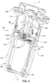
- the camera assembly 182 of the present disclosure may include a fiber optic assembly 300 that provides fiber optic capability integrated into the light head handle 164 for transmission of the optical video signal associated with video data captured by the camera 184 from a location within the handle 164 to the light head housing 116, 122.
- the optical video signal may also be transmitted from the light head housing 116, 122 to elsewhere in the medical device support system 100.
- the fiber optic assembly 300 includes a fiber module 302 located within the handle housing 176 and coupled to the camera assembly 182, for example, coupled to a heat transfer plate 400 thereof, as will be described in greater detail below.
- the fiber module 302 is configured to convert electrical video signals of video data captured by the camera 184 into optical video signals.
- the fiber module 302 includes an optical video signal transmission port 304.
- a tubular interface member 306 is coupled to the optical video signal transmission port 304 and is configured to mate with an optical fiber cable 310.
- a flexible ribbon cable 308 is coupled to the fiber module 302.
- An opposite end 303 of the flexible ribbon cable 308 may be connected to the camera assembly 182, for example, control electronics 305 such as a printed circuit board (PCB) of the camera assembly 182.
- control electronics 305 such as a printed circuit board (PCB) of the camera assembly 182.
- the opposite end 303 of the flexible ribbon cable 308 can be plugged into a connector 305a of the control electronics 305.
- the control electronics 305 are positioned axially between the camera 184 and the gear/pinion arrangement 210, 212 of the camera assembly 182.
- control electronics 305 may be positioned axially between the camera 184 and the accessory port connector 311 in a position axially above the gear/pinion arrangement 210, 212.
- the control electronics 305 include the components of the control system 192, i.e. the controller 194, processor 196, memory 198, and video processing circuit 200.
- the camera 184 may be configured to transmit communications (COMM), power, and a low voltage differential signaling (LVDS) video signal for example 201a in FIG. 8 to the control electronics 305.
- COMM communications
- LVDS low voltage differential signaling
- the control electronics 305 may process the video signal to create a High-Definition Multimedia Interface (HDMI) format electrical video signal for example 201b in FIG. 8 that is transmitted via for example the connector 305a to the flexible ribbon cable 308.
- the fiber module 302 then converts the HDMI electrical video signal to an HDMI optical video signal for example 201c in FIG. 8 .
- HDMI High-Definition Multimedia Interface
- any heat radiated by the fiber module 302 may be transferred to and dissipated by the heat transfer plate 400, as will be described in greater detail below.
- a heat transfer pad 313 may be sandwiched between the fiber module 302 and the heat transfer plate 400 the length of the fiber module 302, that is, to axially opposite ends 302a, 302b of the fiber module 302, and slightly beyond the end 302b.
- the heat transfer pad 313 may be made of any suitable compressible material, for example, a silicone polymer material, or other conformable, thermally conductive material for filling air gaps, including gap fillers, thermal pads, form-in-place pads, sil pads, among others.
- the fiber module 302 may be mounted to the heat transfer plate 400 by a clamping force of the bracket 320, with the heat transfer pad 313 (if provided) compressed therebetween.
- the fiber optic assembly 300 further includes an optical fiber cable 310.
- the optical fiber cable 310 may transmit optical images and/or video signals, for example the afore described HDMI optical video signal 201c, associated with image and/or video data captured by the camera 184.
- the optical fiber cable 310 transmits the optical video signals from the fiber module 302 to elsewhere in the medical device support system 100.
- the optical fiber cable 310 provides a high bandwidth data link suitable for the optical video signal output associated with the afore mentioned camera 184, whether an HD camera, 4K camera or even 8K camera.
- the optical fiber cable 310 provides a high bandwidth capability for the optical video signal to be uncompressed, thereby mitigating for example issues such as visual compression artifacts, noise, and video latency.
- the optical fiber cable 310 may be configured to provide a bidirectional control signal or data/COMM link that links the control electronics 305 (in the illustrative embodiment the control system 192) to for example intelligent display devices.
- the optical fiber cable 310 may provide a unidirectional control signal in that the optical fiber cable 310 provides an optical video signal to drive for example display 202.
- the optical fiber cable 310 may provide a bidirectional control signal in that the optical fiber cable 310 provides receive/transmit control signals between the display 202 and the control electronics 305.
- the optical fiber cable 310 extends from a location within the handle housing 176, in the illustrative embodiment the location at which the optical fiber cable 310 is attached to the fiber module 302, to the light head housing 116, 122. From the light head housing 116, 122, the optical fiber cable 310 may extend to additional components within the light head housing 116, 122 and/or to, for example, the coupling member 112, the yoke assembly 108, the load balancing arm 106, the extension arm 104, the support column 102, or elsewhere in the medical device support system 100. Additionally, or alternately, and with reference to FIGS.
- the optical fiber cable 310 may be coupled to a suitable handle-to-light head housing accessory port connector 311 in the light head housing 116, 122, for example at the location where the handle 164 is rotatably mounted coaxially to the hub 166 of the light head 110, and another optical fiber cable may extend from such accessory port connector 311 to additional components within the light head housing 116, 122 and/or to, for example, the coupling member 112, the yoke assembly 108, the load balancing arm 106, the extension arm 104, the support column 102, or elsewhere in the medical device support system 100.
- the accessory port connector 311 integrates an electrical cable connection with the optical fiber cable 310 connection so that electrical signals, for example electrical power and/or electrical data signals, may be transmitted from the light head housing 116, 122, or from elsewhere in the medical device support system 100, to the handle 164 and the camera assembly 182 therein, or vice versa.
- electrical signals for example electrical power and/or electrical data signals
- Other embodiments are also contemplated.
- the optical video signal is transmitted via the optical fiber cable 310 and/or any additional or alternate cables, to elsewhere in the medical device support system 100, for example, the display 202.
- the control system 192 for controlling components such as the display 202 may be located in the handle housing 176, for example as part of the camera assembly 182 as shown in FIGS. 5 and 8 , or in the light head housing 116, 122 of the light head 110, or outside of the light head housing 116, 122, or even outside of the medical device support system 100, or may be located in a combination of two or more of the handle housing 176, the light head housing 116, 122, outside of the light head housing 116, 122, and outside of the medical device support system 100.
- the optical fiber cable 310 and/or additional or alternate cables may extend through other components of the medical device support system 100, for example, through the yoke assembly 108, load balancing arm 106, extension arm 104, and support column 102.
- the distal end 312 of the optical fiber cable 310 is optically coupled to the fiber module 302.
- Optical image and/or video signals from the fiber module 302 are input from the optical video signal transmission port 304 to the distal end 312 of the optical fiber cable 310.
- the optical fiber cable 310 includes a ferrule 314 and a biasing member 316 proximate the distal end 312 of the optical fiber cable 310. As described below, the ferrule 314 and a biasing member 316 may assist in aligning and retaining the distal end 312 of the optical fiber cable 310 with the optical video signal transmission port 304 in a predetermined arrangement.
- the fiber optic assembly 300 further includes a bracket 320.
- the bracket 320 is mounted to one or more components of the camera assembly 182 within the handle housing 176.
- the bracket 320 is mounted to the heat transfer plate 400 of the camera assembly 182.
- the bracket 320 may alternatively or additionally be mounted to the control electronics 305 such as the printed circuit board (PCB) of the camera assembly 182.
- the fiber module 302 may be sandwiched between the bracket 320 and the heat transfer plate 400, with the heat transfer pad 313, if present, sandwiched between the fiber module 302 and heat transfer plate 400.
- the bracket 320 retains the fiber module 302 in a fixed position relative to the camera 184. In the embodiment shown, the bracket 320 retains the fiber module 302 in an orientation such that the optical video signal transmission port 304 is arranged toward the distal end 177 of the handle 176. The bracket 320 also retains the distal end 312 of the optical fiber cable 310 in a fixed position relative to the camera 184 and relative to the fiber module 302 and optical video signal transmission port 304.
- the bracket 320 includes an interface retention portion 322 and a cable retention portion 324.
- a fastening member 325 is located between and connects or bridges the interface retention portion 322 and the cable retention portion 324.
- the cable retention portion 324 of the bracket 320 is configured as a channel 326 including a bottom wall 328 and side walls 330, 332.
- the channel 326 extends between a proximal end 334 and a distal end 336 along a direction C.
- the side walls 330, 332 extend in a height direction H from the bottom wall 332.
- the fastening member 325 is connected to one of the side walls 330 of the channel 326.
- the side walls 330, 332 at the proximal end 334 are tapered.
- the side walls 330, 332 have a constant height between the proximal end 334 and the distal end 336.
- the cable retention portion 324 may also be referred to as a guide channel in that it guides the optical fiber cable 310 within the handle housing 176 and toward the light head housing 116, 122.
- the interface retention portion 322 of the bracket 320 includes an interface channel 338 including a bottom wall 340 and side walls 342, 344.
- the interface channel 338 extends between a proximal end 346 and a distal end 348 along a direction B.
- the side walls 342, 344 extend in a height direction H from the bottom wall 340.
- a distal wall 350 is located at the distal end 348 of the interface channel 338 and extends between the side walls 342, 344 and in the height direction H.
- the distal wall 350 is arranged orthogonal to the side walls 342, 344 of the interface channel 338.
- a slot 352 is provided in the distal wall 350 that provides for fluid communication through the distal wall and into the interface channel 338.
- a proximal wall 354 is located at the proximal end 346 of the interface channel 338 and extends between the side walls 342, 344 and in the height direction H.
- the proximal wall 354 is arranged orthogonal to the side walls 342, 344 of the interface channel 338.
- a slot 356 is provided in the proximal wall 354 that provides for fluid communication through the proximal wall 354 and into the interface channel 338.
- a fiber module retention channel 358, 360 extends along the height direction H between a proximal end 362, 364 and a distal end 366, 368.
- Each fiber module retention channel 358, 360 includes a bottom wall 370, 372 and side walls 354, 374, 376, wherein a portion of the distal wall 354 forms a side wall of each of the fiber module retention channels 358, 360.
- Retention walls 378, 380 extend from the side walls 374, 376 of each fiber module retention channel 358, 360.
- the retention walls 378, 380 extend from the side wall 374, 376 at the distal ends 366, 368 of the fiber module retention channels 358, 360.
- each retention wall 378, 380 is oriented parallel to the bottom wall 340 of the interface channel 338.
- the fastening member 325 includes an orifice 382 (e.g., a bolt hole) through which a fastener 384 (e.g., screw, rivet, etc.) may be inserted for securing the bracket 320 to another member, such as the heat transfer plate 400 or other component of the camera assembly 182.
- a fastener 384 e.g., screw, rivet, etc.
- the fastening member 325 may include any suitable coupling mechanism and arrangement to fix the bracket 320 to the camera assembly 182.
- the fastening member 325 may include a bolt hole pattern through which fasteners (e.g., screws, rivets, etc.) may be respectively inserted for securing the bracket 320.
- the fastening member 325 may have an arrangement of one or more tabs configured to mate with one or more orifices on the camera 184 or other component(s) of the camera assembly 182. In other embodiments, the fastening member 325 may have a surface that may be adhered to a surface of a component of the camera assembly 182 by an adhesive.
- the interface retention portion 322 and cable retention portion 324 are arranged such that the channel 326 of the cable retention portion 324 and the interface channel 338 of the interface retention portion 322 are parallel to one another in a direction orthogonal to the height direction H. In other embodiments, the interface retention portion 322 and cable retention portion 324 are arranged such that the channel 326 of the cable retention portion 324 and the interface channel 338 of the interface retention portion 322 are arranged non-parallel to one another in a direction orthogonal to the height direction H.
- the bracket 320 may be secured to the camera assembly 182 and may retain the fiber module 302 in optical communication with the distal end 312 of the optical fiber cable 310.
- the distal end of the optical fiber cable 310 may be inserted into the tubular member 306 of the fiber module 302.
- the distal end 312 of the optical fiber cable 310 may be set at a predetermined distance from the output (e.g., lens) of the optical video signal transmission port 304. This distance may be set based on the length of the tubular member 306 and the position of the ferrule 314 on the optical fiber cable 310 relative to the distal end 312 of the optical fiber cable 310.
- the outer diameter of the ferrule 314 may be larger than the inner diameter of the tubular member 306 such that ferrule 314 contacts the distal end 307 of the tubular member 306 and prevents the optical fiber cable 310 from being inserted any further into the tubular member 306.
- the position of the ferrule 314 is on the optical fiber cable 310 is adjustable.
- the predetermined distance between the distal end 312 of the inserted optical fiber cable 310 and the output (e.g., lens) of the optical video signal transmission port 304 may be any suitable distance. In some embodiments, the distance ranges from 0.1 mm to 1 cm. In other embodiments, the distance is less than 0.1 mm. It will also be appreciated that in some embodiments, the distal end 312 of the inserted optical fiber cable 310 may be in contact with the output of the optical video signal transmission port 304 such that the distance is zero mm.
- the tubular member 306 defines an aperture at which the ferrule 314 seats to align the distal end 312 of the optical fiber cable 310 with an optical video signal transmission port 304 of the fiber module 302.
- the ferrule 314 seats at the distal end 307 of the tubular member 306 to laterally align the optical fiber cable 310 with an axis of the optical video signal transmission port 304 of the fiber module 302.
- the ferrule 314 seats at the tubular member 306 to angularly align the optical fiber cable 310 with an axis of the optical video signal transmission port 304 of the fiber module 302.
- the fiber module 302 includes a flange 309 that slidably fits into the fiber module retention channels 358, 360. With the flange 309 inserted in the fiber module retention channels 358, 360, the fiber module 302 is restricted in movement in a direction along the direction B of the interface channel. The flange 309 of the fiber module 302 is inserted into the fiber module retention channels 358, 360 from a direction proximate the open top surface of the channel, and the retention walls 378, 380 prevent the fiber module 302 from extending past a predetermined position along the height direction H.
- a biasing member 316 is provided on the optical fiber cable 310 at a side of the ferrule 314 opposite the distal end 312 of the optical fiber cable 310.
- the biasing member 316 is a spring 316.
- the biasing member 316 is a compressible, resilient material such as a rubber, foam, and the like.
- the biasing member 316 provides a continuous biasing force against the ferrule 314 to retain the ferrule 314 against the distal end 317 of the tubular member 306, thereby retaining the distal end 312 of the optical fiber cable 310 in the predetermined position relative to the output (e.g., lens) of the optical video signal transmission port 304 of the fiber module 302.
- a sheath 315 may be provided around the optical fiber cable 310 proximate the distal end 312 of the optical fiber cable 310.
- the ferrule 314 and biasing member 316 are disposed between the distal end 312 of the optical fiber cable 310 and the sheath 315.
- the sheath 315 may also pass through the slot 352 in the distal wall 350.
- the sheath 350 may provide a stiffness that inhibits or prevents the optical fiber cable 310 from bending or increases the optical fiber cable's resistance to bending proximate the distal wall 350.
- the retention walls 378, 380 hold the fiber module 302 against the camera assembly 182; and the distal wall 350, proximal wall 354, and/or bottom surface 340 of the interface channel and bottom surface of the interface channel hold the distal end 312 of the optical fiber cable 310 against the camera assembly 182.
- the optical fiber cable 310 is routed through the distal wall of the interface retention portion, is curved, and is routed through the cable retention portion 324 of the bracket 320.
- the curvature of the optical fiber cable 310 has a radius of curvature (bend radius) that allows for the optical signal to propagate in the optical fiber without or with an acceptable minimum loss of the signal.
- the radius of curvature is 1 cm to 4 cm.
- a suitable optical fiber cable 310 may be, for example, a multimode (MM) 50 micron OM4 bend insensitive fiber.
- the optical fiber cable 310 may be a single mode (SM) fiber, or a multimode (MM) fiber of 62.5 micron diameter.
- SM single mode
- MM multimode
- the optical fiber cable 310 may comprise an OM5 or OM6 designated fiber.
- the cable retention portion 324 and the interface retention portion 322 are separated from one another by a predetermined distance so as to set a radius of curvature of the optical fiber cable 310 that allows for transmission of the optical video signal.
- the distance between the channel 326 of the cable retention portion 324 and the channel 338 of the interface retention portion 322 is 2 cm to 8 cm.
- the optical fiber cable 310 is fixed in the channel 326 of the cable retention portion 324.
- the diameter of the optical fiber cable 310 relative to the channel 326 may be such that the optical fiber cable 310 is prevented from freely moving through the channel 326 due to frictional forces between the optical fiber cable 310 and the channel 326.
- the optical fiber cable 310 is freely movable within the channel 326.
- the optical fiber cable 310 is routed through the cable retention portion 324 of the bracket 320 and to the light head housing 116, 122.
- the optical fiber cable 310 may be routed in any suitable manner between the bracket 320 and the light head housing 116, 122, so long as an acceptable bend radius of the optical fiber cable 310 is maintained.
- the cable retention portion 324 of the bracket 320 retains the optical fiber cable 310 while also allowing slack in the optical fiber cable 310 between the cable retention portion 324 and the light head housing 116, 122.
- the slack in the optical fiber cable 310 may allow for flexibility in the optical fiber cable 310 during rotation of the camera assembly 182 so that, for example, the optical fiber cable 310 merely bends and flexes as needed between the cable retention portion 324 and for example the accessory port connector 311 in the light head housing 116, 122, as shown in FIGS. 4-6 , 14 and 15 .
- the optical fiber cable 310 is curved with a suitable bend radius and routed through the spindle 206 and to the light head housing 116, 122.
- the optical fiber cable 310 and/or any additional or alternate cables may be routed in any suitable manner through the components of the medical device support system 100 to reach for example the display 202 or other components of the system 100.
- the distal end 312 of the optical fiber cable 310 includes the ferrule 314 and the bracket 320 includes the interface channel 338 within which the ferrule 314 seats to align the distal end 312 of the optical fiber cable 310 with the optical video signal transmission port 304 of the fiber module 302.
- the bracket 320 includes the biasing member 316 that exerts a continuous force against the ferrule 314 to compress the distal end 312 of the optical fiber cable 310 against the optical video signal transmission port 304 of the fiber module 302.
- the interface channel 338 has at its opposite ends the distal wall 350 and the fiber module 302 respectively, and, as shown in FIG.
- the biasing member 316 has a first end that exerts the continuous force against the ferrule 314 and a second end that abuts the distal wall 350.
- the bracket 320 includes the guide channel 326 that guides the optical fiber cable 310 within the handle housing 176 and to the light head housing 116, 122.
- the optical fiber cable 310 has a bend radius as it passes between the distal wall 350 and the light head housing 116, 122.
- the camera assembly 182 may include a heat transfer plate 400.
- the bracket 320 may be fixed to the camera assembly 182 such that the bracket 320 and the fiber module 302 are in contact with the heat transfer plate 400.
- the heat transfer plate 400 may be made from metal or any other suitable heat transfer material. The heat transfer plate 400 is in heat transmissive contact with the fiber module 302 to draw heat away from the fiber module 302.
- FIGS. 16-19 show that the heat transfer plate 400 includes a main body 402 having major surfaces 404, 406 spaced apart from one another in a thickness direction T.
- the main body 402 is shown as having planar major surfaces 404, 406, although it will be appreciated that in other embodiments, the main body 402 (and the major surfaces thereof) may be curved in one or more directions.
- the perimeter of the main body 402 (viewed in a direction normal to the major surfaces, such as that shown in FIG. 18 ) may have any suitable shape.
- the main body 402 has a perimeter including protrusions 408, 410, 412, 414 such that the profile of the major surfaces allow for the bracket 320 to at least partially correspond to the perimeter of the bracket 320, as well as the fiber module 302 when mounted to the bracket 320. This may allow for increased contact between the bracket 320 and the heat transfer plate 400, as well as the fiber module 302 and the heat transfer plate 400.
- the main body 402 of the heat transfer plate 400 includes one or more orifices 418, which may allow for the heat transfer plate 400 to be mounted (e.g., via a fastener such as a screw, rivet, etc.) to the camera assembly 182 and/or may allow for the bracket 320 to be mounted (e.g., via a fastener such as a screw, rivet, etc.) to the heat transfer plate 400.
- a fastener such as a screw, rivet, etc.
- the heat transfer plate 400 may be coupled to a heat sink to provide further dissipation of heat from the fiber module 302.
- the heat transfer plate 400 includes a tab 416 that is arranged orthogonal to the main body 402 of the heat transfer plate 400.
- the tab 416 includes an orifice 418 through which the tab 416 may be secured (e.g., via a fastener such as a screw, rivet, etc.) to a separate heat sink in the camera assembly 182.
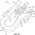
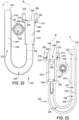
- FIGS. 20-23 show another exemplary embodiment of the bracket 320.
- the interface retention portion 322 and the fastening portion 325 are similar to that described above with respect to the bracket 320 shown in FIGS. 9-15 , and the features thereof will not be repeated for the sake of brevity.
- the cable retention portion 324 includes a channel 326 that is in contact with the distal wall 348 of the interface retention portion 322.
- the channel 326 includes a bottom wall 328 and side walls 330, 332, and the channel 326 includes a linear portion 327 and a curved portion 329.
- the curved portion of the channel has a predetermined radius of curvature (bend radius) and serves a guide for setting and maintaining the radius of curvature of the optical fiber cable 310. It will be appreciated that the bracket shown in FIGS. 20-23 may be implemented in any of the embodiments of the handle shown and described in the present disclosure.
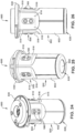
- the handle 164 includes a handle housing 176 that has an upper generally tubular section 500 mounted to the light head housing 116, 122 and a lower generally tubular section 502 extending downward from a bottom of the upper generally tubular section 500.
- the outer perimeter of the lower generally tubular section 502 is relatively wider in axial cross section than the outer perimeter of the upper generally tubular section 500 over a portion, for example a plurality of recesses 510, of the upper generally tubular section 500.
- the width at the axial cross section is perpendicularly across the center axis of the handle housing 176, which in the illustrative embodiment coincides with the afore described rotation axis R.
- the width in axial cross section of the lower generally tubular section 502 is greater than the width in axial cross section of the upper generally tubular section 500 over the portion where the plurality of recesses 510 are provided in the upper generally tubular section 500.
- the lower generally tubular section 502 may be cylindrical in shape, as shown, or non-cylindrical in shape.
- the upper generally tubular section 500 may be generally square tubular in shape, as shown, or non-generally square tubular in shape.
- the generally square tubular shape of the upper generally tubular section 500 includes the four curved recesses 510 forming the four sides of the square shape and four relatively smaller size curved corners 514 disposed between respective adjacent recesses 510.
- the upper generally tubular section 500 has recesses 510 and curved corners 514 disposed in alternate fashion around the outer perimeter of the upper generally tubular section 500, that is, disposed about the center axis (rotation axis R) of the handle housing 176.
- the shape of the upper generally tubular section 500 need not be limited to a generally square shape and the quantity of recesses 510 need not be limited to four. Other embodiments are contemplated.
- the upper generally tubular section 500 may have any polygonal shape in axial cross section, for example three, five, or six recesses 510, in which case, the upper generally tubular section 500 would have, respectively, a generally triangular tubular shape, a generally pentagonal tubular shape, or a generally hexagonal tubular shape.
- the upper generally tubular section 500 and lower generally tubular section 502 may be made of a single monolithic structure, as shown, or a multi-piece construction.
- the single monolithic structure may be formed by a net shape manufacturing technique or near net shape manufacturing technique, and may include, for example, an injection molded structure or a 3D printed structure.
- the upper generally tubular section 500 may include a flange 530 that protrudes radially outwardly relative to the recesses 510 and curved corners 514.
- the flange 530 may cover, for example, mounting structure of the handle 164 and/or mounting structure of the light head housing 116, 122 to which the handle 164 is mounted.
- the width in axial cross section of the lower generally tubular section 502 where the lower generally tubular section 502 transitions to the upper generally tubular section 500 is equal to the width in axial cross section of the upper generally tubular section 500 at the curved corners 514.
- each recess 510 includes a surface 516 recessed radially inwardly relative to the outer perimeter of the lower generally tubular section 502 and recessed radially inwardly relative to the curved corners 514 of the upper generally tubular section 500.
- the surfaces 516 may be curved, as shown, or planar (the secant of a circle defined at the radius of the curved corners 514), it being understood that a curved recess generally will provide more capacity inside the handle housing 176 than a planar recess.
- the outer perimeter of the handle housing 176 tapers downwardly from the upper most portion of the upper generally tubular section 500 to the lower most portion of the lower generally tubular section 502.
- the upper generally tubular section 500 may taper downwardly without the lower generally tubular section 502 doing so, or the lower generally tubular section 502 may taper downwardly without the upper generally tubular section 500 doing so.
- the outer perimeter of the handle housing 176 may not include a taper.
- the amount of protrusion from the surfaces 516 is such that the tops or radially outermost portions of the buttons 180 extend radially outwardly relative to the radial extent in axial cross section of the outer perimeter of the lower generally tubular section 502, or alternately extend radially outwardly approximately to the same radial extent as the outer perimeter of the lower generally tubular section 502.
- This provides an ergonomic reach to the buttons 180, for example by the thumb of the user's hand, while enabling the user to maintain a grip on the lower generally tubular section 502 by the other digits and palm of the user's hand.
- the handle 164 allows the camera 184 and other components of the camera assembly 182 to be integrated within the handle 164 while maintaining an ergonomic grip and ergonomic button 180 operation.
- the inventors have found that commonly available cameras, for example HD, 4K or 8K block cameras, may be so large in size that incorporating such cameras into a surgical light head handle creates incompatibilities with maintaining the handle's ergonomics.
- the handle 164 advantageously provides an ergonomic shape and ergonomic size handle housing 176 while incorporating a suitable camera 184 within the handle housing 176.
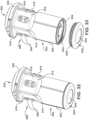
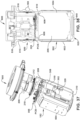
- FIGS. 24-38 there is shown a handle 600 in accordance with the invention.
- the handle 600 is in many respects similar to the above-referenced handle 164 shown in FIGS. 3 and 4 , and consequently the same reference numerals are used in FIGS. 24-38 to denote structures corresponding to similar structures in the handle 164.
- the foregoing description of the handle 164 is equally applicable to the handle 600 and the following description of the handle 600 is equally applicable to the handle 164, except where differences are noted herein.
- aspects of the handles 164, 600 may be substituted for one another or used in conjunction with one another where applicable.
- the bottom of the lower generally tubular section 502 is open downward.
- a camera 604 is sized for insertion through the open bottom of the lower generally tubular section 502 to within a handle housing 602 of the handle 600 and axially above the open bottom of the lower generally tubular section 502.
- the handle housing 602 of the FIGS. 24-38 embodiment differs from the handle housing 176 of the FIGS. 3 and 4 embodiment in that, as shown in FIG. 38 , the inner perimeter of the lower generally tubular section 502 is relatively wider in axial cross section than the inner perimeter of the upper generally tubular section 500 whereas in the FIGS.
- the inner perimeter of the lower generally tubular section 502 has approximately the same width in axial cross section as the inner perimeter of the upper generally tubular section 500, assuming a negligible effect in the taper of the handle housing 176 and handle housing 602. This is accomplished in the illustrative embodiment by a shoulder 606 that transitions radially outwardly from the inner perimeter of the upper generally tubular section 500 to the inner perimeter of the lower generally tubular section 502.
- the relatively wider inner perimeter of the lower generally tubular section 502 of the handle housing 602 enables the handle housing 602 to accommodate a wider camera 604, that is, a camera 604 that is relatively wider in axial cross section than the width of the inner perimeter of the upper generally tubular section 500 yet relatively narrower in axial cross section than the width of the inner perimeter of the lower generally tubular section 502.
- a wider camera 604 that is relatively wider in axial cross section than the width of the inner perimeter of the upper generally tubular section 500 yet relatively narrower in axial cross section than the width of the inner perimeter of the lower generally tubular section 502.
- the camera 604 is relatively wider in axial cross section than the width of the inner perimeter of the upper generally tubular section 500 yet still fits within the inner perimeter of the lower generally tubular section 502.
- the camera 604 is configured to be inserted into and contained within the inner perimeter of the lower generally tubular section 502 but not into or within the inner perimeter of the upper generally tubular section 500. This is regardless of the position of the camera 604 about the center axis of the handle housing 602. At least one axial cross section across the width of the camera 604, that is perpendicularly across the center axis of the handle housing 602, is relatively wider than any width in axial cross section across the width of the inner perimeter of the upper generally tubular section 500, that is perpendicularly across the center axis of the handle housing 602.
- a cap 620 is removably mounted to the bottom of the lower generally tubular section 502 to close the open bottom in the lower generally tubular section 502.
- the bottom of the lower generally tubular section 502 includes a cylindrical shape threaded region 624 and the cap 620 includes a round shape mating threaded region 626.
- the cap 620 is removably mounted to the bottom of the lower generally tubular section 502 by engagement between the round shape mating threaded region 626 of the cap 620 and the cylindrical shape threaded region 624 of the bottom of the lower generally tubular section 502.
- the threaded connection of the detachable cap 620 allows for easy removal and installation of the cap 620 without any additional hardware, components, or tools such as fasteners or a screwdriver. With the cap 620 mounted to the handle housing 602, there is no exposed hardware and, consequently, cleanability is improved. Further, the removability of the cap 620 enables access to the downwardly opening bottom of the handle 600 and thus easy installation and/or replacement of the camera 604 or other components of the camera assembly 182 from the bottom of the handle housing 602 rather than for example removing the handle 600 from the light head housing 116, 122 and accessing the inside of the handle 600 through the top of the handle housing 602. The removability of the cap 620 also simplifies replacement of a camera glass 640 that forms part of the cap 620.
- the cylindrical shape threaded region 624 is an external thread and the round shape mating thread 626 is an internal thread.
- the cylindrical shape threaded region 624 may be an internal thread and the round shape mating thread 626 may be an external thread.
- the handle 600 includes a single printed circuit board (PCB) that is disposed in the handle housing 602.
- the handle 600 differs from the handle 164 of the FIGS. 3-6 embodiment in that the handle 600 has a single PCB disposed in the handle housing 602 whereas the handle 164 has two PCBs disposed in the handle housing 176.
- the PCB, or PCBs as the case may be provides control electronics 305 for controlling the camera assembly 182 including the camera 184 in the FIGS. 3-6 embodiment or the camera 604 in the FIGS. 24-38 embodiment.
- the use of a single PCB instead of two or more PCBs reduces the volumetric footprint required by the PCB.
- the single PCB is disposed in the upper generally tubular section 500 of the handle housing 602, for example, within the inner perimeter of the upper generally tubular section 500. As shown in FIG. 38 , the single PCB is relatively narrower in axial cross section than the width of the inner perimeter of the upper generally tubular section 500.
Landscapes
- Health & Medical Sciences (AREA)
- Surgery (AREA)
- Life Sciences & Earth Sciences (AREA)
- Engineering & Computer Science (AREA)
- Nuclear Medicine, Radiotherapy & Molecular Imaging (AREA)
- Physics & Mathematics (AREA)
- Medical Informatics (AREA)
- General Health & Medical Sciences (AREA)
- Oral & Maxillofacial Surgery (AREA)
- Veterinary Medicine (AREA)
- Biomedical Technology (AREA)
- Heart & Thoracic Surgery (AREA)
- Public Health (AREA)
- Molecular Biology (AREA)
- Animal Behavior & Ethology (AREA)
- Pathology (AREA)
- General Physics & Mathematics (AREA)
- Optics & Photonics (AREA)
- Multimedia (AREA)
- General Engineering & Computer Science (AREA)
- Gynecology & Obstetrics (AREA)
- Radiology & Medical Imaging (AREA)
- Endoscopes (AREA)
- Accessories Of Cameras (AREA)
- Radiation-Therapy Devices (AREA)
- Vessels And Coating Films For Discharge Lamps (AREA)
Description
- The technology of the present disclosure relates generally to a surgical lighting system, and more specifically to a light head for a medical device support system, suspension system, and/or carry system including a camera assembly.
- Light heads for medical device support systems, suspension systems and/or other carry systems, are used in health treatment settings such as hospital examination rooms, clinics, surgery rooms and emergency rooms to illuminate a region of interest (e.g., surgical treatment site or other medical site) below or proximate the light head. The light heads typically include a housing, one or more light emitting elements mounted inside the housing, and a handle mounted to the housing to enable a healthcare professional or other individual to adjust the position of the light head according to the needs of a specific medical procedure. The handle is typically formed to have an ergonomic structure that enables a user to wrap a hand around the handle such that the internal space within the handle is limited.
- In these health treatment settings, there is often a need to capture and/or record images or video of the region of interest. The images or video may be used for various purposes, such as a visual aid in performing a given procedure. One or more cameras may be included as a part of the medical device support system, suspension system and/or other carry system. For example, a camera may be mounted in the handle of the light head and arranged to capture images of the region of interest that is illuminated by the one or more light emitting elements of the light head. However, the type of camera used in the handle of the light head has been limited due to issues of adjustability and/or reliability of the camera, particularly in view of the limited space within the handle.
US6633328 discloses a surgical video system which captures an image of a surgical procedure and displays the image on a video monitor remote from the surgical procedure.US2019209261 discloses a handle assembly comprised of a base and a detachable handle that mounts to the base. The base includes integrated electronics, such as switches. The detachable handle includes buttons for activating the switches. - Further, a sterile handle in a surgical environment has ergonomic needs whereby a too large handle may be undesirable and, in some cases, unacceptable.
- Accordingly, there remains a need for further contributions in this area of technology.
- The present disclosure relates to a camera assembly arranged in a surgical light head handle. An exemplary application of the surgical light head includes a surgical light such as those used in operating rooms to provide increased light to a specific area of the room (e.g., a region of interest). Embodiments of the present disclosure allow for integration of fiber optic capability into the light head handle for transmission of an optical video signal from the camera in the handle to the light head housing. Embodiments of the present disclosure also provide for thermal management of heat generated in connection with one or more components of the fiber optic assembly.
- According to the invention, a surgical lighting system includes a light head housing including a plurality of light emitting elements therein that are arranged to emit light downward to a region of interest; a handle mounted to the light head housing and protruding downward from the light head housing, the handle including a handle housing having a sufficient size to be gripped by the human hand; and a camera mounted within the handle housing, the camera having a field of view that encompasses at least a portion of the region of interest; wherein the handle housing has an upper generally tubular section mounted to the light head housing and a lower generally tubular section extending downward from a bottom of the upper generally tubular section, the outer perimeter of the lower generally tubular section being relatively wider in axial cross section than the outer perimeter of the upper generally tubular section over a portion of the upper generally tubular section, wherein a bottom of the lower generally tubular section is open downward and the camera is sized for insertion through the open bottom to within the handle housing and axially above the open bottom.
- Embodiments of the invention may include one or more of the following additional features separately or in combination.
- The lower generally tubular section may be cylindrical in shape.
- The upper generally tubular section may be generally square tubular in shape with curved corners.
- The lower generally tubular section may be cylindrical in shape, the upper generally tubular section may be generally square tubular in shape with curved corners, and the width in axial cross section of the lower generally tubular section where the lower generally tubular section transitions to the upper generally tubular section may be equal to the width in axial cross section of the upper generally tubular section at the curved corners.
- The upper generally tubular section may include buttons for controlling attributes of the emitted light from the light head.
- The surgical lighting system may further include a cap removably mounted to the bottom of the lower generally tubular section to close the open bottom in the lower generally tubular section.
- A bottom of the lower generally tubular section may include a cylindrical shape threaded region and the cap may include a round shape mating threaded region, and the cap may be removably mounted to the bottom of the lower generally tubular section by engagement between the round shape mating threaded region of the cap and the cylindrical shape threaded region of the bottom of the lower generally tubular section.
- An inner perimeter of the lower generally tubular section may be relatively wider in axial cross section than an inner perimeter of the upper generally tubular section.
- The surgical lighting system may further include a shoulder that transitions radially outwardly from the inner perimeter of the upper generally tubular section to the inner perimeter of the lower generally tubular section.
- The camera may be relatively wider in axial cross section than the width of an inner perimeter of the upper generally tubular section and the camera may be relatively narrower in axial cross section than the width of an inner perimeter of the lower generally tubular section.
- The camera may be configured to be inserted into and contained within an inner perimeter of the lower generally tubular section but not into or within an inner perimeter of the upper generally tubular section.
- The surgical lighting system may further include a single printed circuit board (PCB) disposed in the handle housing.
- The single PCB may be relatively narrower in axial cross section than the width of an inner perimeter of the upper generally tubular section.
- These and further features will be apparent with reference to the following description and attached drawings which set forth certain illustrative embodiments of the invention. These embodiments are indicative, however, of but a few of the various ways in which the principles of the invention may be employed. Other objects, advantages and novel features according to aspects of the invention will become apparent from the following detailed description when considered in conjunction with the drawings.
- Features that are described and/or illustrated with respect to one embodiment may be used in the same way or in a similar way in one or more other embodiments and/or in combination with or instead of the features of the other embodiments.
- The annexed drawings, which are not necessarily to scale, show various aspects of the present disclosure.
-
FIG. 1 is a side elevation view of an overall configuration of a medical device support system in accordance with an embodiment of the present disclosure, showing a top of a left positioned light head and a bottom of a right positioned light head. -
FIG. 2 is a side cross section view of a light head in accordance with an embodiment of the present disclosure, showing a housing base, a housing cover, and internal components of the light head and handle. -
FIG. 3 is a perspective side view of a handle in accordance with an embodiment of the present disclosure having a handle housing including a grip portion. -
FIG. 4 is a perspective cross section view of the handle ofFIG. 3 . -
FIG. 5 is an exploded perspective view of parts of the handle ofFIG. 3 with the handle housing removed. -
FIG. 6 is a perspective cross section view of parts of the handle ofFIG. 3 with the handle housing removed. -
FIG. 7 shows a region of interest illuminated by a light head and a field of view of a camera in the handle of the light head. -
FIG. 8 is a schematic view of exemplary control system and display coupled to the camera assembly. -
FIG. 9 is a front perspective view of a bracket in accordance with an embodiment of the present disclosure. -
FIG. 10 is a rear perspective view of the bracket ofFIG. 9 . -
FIG. 11 is a front elevation view of the bracket ofFIG. 9 . -
FIG. 12 is a rear elevation view of the bracket ofFIG. 9 . -
FIG. 13 is a rear perspective view showing the bracket ofFIG. 9 and parts of a fiber optic assembly. -
FIG. 14 is a front perspective view showing the bracket ofFIG. 9 and parts of a fiber optic assembly and handle. -
FIG. 15 is a rear perspective view showing the bracket and parts of the fiber optic assembly and handle. -
FIG. 16 is a front perspective view of a heat transfer plate in accordance with an embodiment of the present disclosure. -
FIG. 17 is a top view of the heat transfer plate ofFIG. 16 . -
FIG. 18 is a front elevation view of the heat transfer plate ofFIG. 16 . -
FIG. 19 is a side elevation view of the heat transfer plate ofFIG. 16 . -
FIG. 20 is a front perspective view of a bracket in accordance with another embodiment of the present disclosure. -
FIG. 21 is a rear perspective view of the bracket ofFIG. 20 . -
FIG. 22 is a front elevation view of the bracket ofFIG. 20 . -
FIG. 23 is a rear elevation view of the bracket ofFIG. 20 . -
FIG. 24 is a top perspective view of a handle in accordance with another embodiment of the present disclosure having a handle housing including a grip portion. -
FIG. 25 is a bottom perspective view of theFIG. 24 handle. -
FIG. 26 is a front elevation view of theFIG. 24 handle, as viewed from the front ofFIG. 24 and showing buttons in the plane of the paper. -
FIG. 27 is a side elevation view of theFIG. 24 handle, as viewed from the left ofFIG. 25 . -
FIG. 28 is a side elevation view of theFIG. 24 handle, as viewed from the front ofFIG. 25 . -
FIG. 29 is a side elevation view of theFIG. 24 handle, as viewed from the right ofFIG. 25 . -
FIG. 30 is a top plan view of theFIG. 24 handle. -
FIG. 31 is a bottom plan view of theFIG. 24 handle. -
FIG. 32 is a bottom perspective view of theFIG. 24 handle. -
FIG. 33 is similar toFIG. 32 except exploded to show a cap of the handle removed. -
FIG. 34 is similar toFIG. 27 except exploded to show a cap of the handle removed. -
FIG. 35 is similar toFIG. 28 except exploded to show a cap of the handle removed. -
FIG. 36 is similar toFIG. 29 except exploded to show a cap of the handle removed. -
FIG. 37 is an exploded perspective view of parts of the handle ofFIG. 24 with the handle housing removed. -
FIG. 38 is a cross section view of the handle ofFIG. 24 . - For the purpose of promoting an understanding of the principles of the present disclosure, reference will now be made to the embodiments illustrated in the drawings and specific language will be used to describe the same. It will nevertheless be understood that no limitation of the scope of the present disclosure is thereby intended. The figures are not necessarily to scale. Features that are described and/or illustrated with respect to one embodiment may be used in the same way or in a similar way in one or more other embodiments and/or in combination with or instead of the features of the other embodiments. Any alterations and further modifications of the described embodiments, and any further applications of the principles of the present disclosure as described herein, are contemplated as would normally occur to one skilled in the art to which the present disclosure relates.
- With reference to
FIG. 1 , an exemplary medical device support system is shown at 100. The medicaldevice support system 100 includes a central shaft orsupport column 102 that is suspended from the ceiling, and two generallyhorizontal extension arms 104 mounted to theshaft 102 for rotational movement about thecentral shaft 102. In other implementations, thecentral shaft 102 could be mounted to a wall or stand rather than the ceiling. Twoload balancing arms 106 are pivotably mounted to the distal ends of therespective extension arms 104.Yoke assemblies 108 are mounted to the distal ends of the respectiveload balancing arms 106. Theyoke assemblies 108, in turn, support respective light heads 110 for multi-axis movement relative to theload balancing arms 106. Eachlight head 110 includes a bushing orother coupling member 112 that rotatably connects thelight head 110 to the distal end of anarm 114 of arespective yoke assembly 108, as shown. Theload balancing arms 106 andyoke assemblies 108 enable positioning of the light heads 110 to a desired orientation relative to, for example, a patient operating table and healthcare professionals in the operating room. - The exemplary medical device support system shown in
FIG. 1 includes twolight heads 110, each mounted to arespective extension arm 104, load balancingarm 106, andyoke assembly 108. It will be appreciated that in other embodiments, the medical device support system may include more or fewer light heads. It will also be appreciated that the medical device support system may include other accessories mounted to thecentral shaft 102. - With additional reference to
FIG. 2 , eachlight head 110 of thesystem 100 includes ahousing base 116, a plurality oflight emitting elements 118, anannular shape lens 120, and ahousing cover 122 including ahousing lens 124. Thehousing base 116 and thehousing cover 122 are connected byfasteners 126. Theannular shape lens 120 and thehousing lens 124 are in a light emitting path of the plurality oflight emitting elements 118. - As shown in
FIGS. 1 and2 , eachlight head 110 includes an annular shapeouter portion 128, aninner round portion 130, and aradially protruding arm 132 that connects the annular shapeouter portion 128 to theinner round portion 130. In the illustrative embodiment, theradially protruding arm 132 arranges the annular shapeouter portion 128 and theinner round portion 130 in concentric relation to one another, and in concentric relation to the rotation axis A-A of theannular shape lens 120. Theradially protruding arm 132 also houses one or more components for transferring rotational motion from ahandle 164 mounted to thelight head housing light head 110 to theannular shape lens 120 of the light head 110 (described in more detail below). It will be appreciated that the annular shapeouter portion 128 and theinner round portion 130 need not be in concentric relation to one another and instead can be arranged by the protruding arm in eccentric relation to one another. It will further be appreciated that in an alternate embodiment theinner round portion 130 of thelight head 110 may be omitted; and in such form, only the annular shapeouter portion 128 emits light to the region of interest (e.g., surgical treatment site or other medical site) below or proximate the light head. - As shown in
FIG. 2 , aninside surface 134 of thehousing base 116 supports the plurality oflight emitting elements 118. Thelight emitting elements 118 may in some embodiments include one or more solid-state light emitters. Exemplary solid-state light emitters include such devices as light emitting diodes (LEDs), laser diodes, and organic LEDs (OLEDs). The LEDs may be broad spectrum LEDs (e.g., white light emitters) or LEDs that emit light of a desired color or spectrum (e.g., red light, green light, blue light, or ultraviolet light). In other embodiments, the LEDs may be a mixture of broad-spectrum LEDs and LEDs that emit narrow-band light of a desired color, or a mixture of LEDs that emit different respective colors or spectrum. In some embodiments, the solid-state light emitters constituting thelight emitting elements 118 all generate light having the same nominal spectrum. In other embodiments, at least some of the solid-state light emitters constituting thelight emitting elements 118 generate light that differs in spectrum from the light generated by the remaining solid-state light emitters. In other embodiments, thelight emitting elements 118 may include one or more other types of light sources. Non-limiting examples of light sources include halogen, fluorescent, compact fluorescent, incandescent, and the like. In still other embodiments, thelight emitting elements 118 may include a combination of solid-state light emitters and one or more of the above other types of light sources. - A controller controls the
light emitting elements 118 of the annular shapeouter portion 128 and theinner round portion 130 to emit light to a region of interest (e.g., surgical treatment site or other medical site) below or proximate thelight head 110. For example, a controller may control thelight sources 118 of the annular shapeouter portion 128 and theinner portion 130 to emit light to a region of interest below thelight head 100. Control of the respectivelight sources 118 may be performed, for example, collectively, individually, in groups, by section, or in any other suitable manner. In some embodiments, the controller may be provided as part of thelight head 110 such as shown inFIG. 8 where the controller is part of acamera assembly 182 within thehandle 164 of thelight head 110. In other embodiments, the controller may be implemented elsewhere in the medicaldevice support system 100 external to thecamera assembly 182, for example elsewhere in thelight head 110 or external to thelight head 110, or the controller may be implement external to the medicaldevice support system 100. - With continued reference to
FIG. 2 , a plurality ofcollimators 136 are mounted to theinside surface 134 of thehousing base 116 and in the light emitting paths of the respective plurality oflight emitting elements 118. Each collimator may be associated with a respectivelight emitting element 118 and may be arranged such that at least a portion of the light emitted from the associatedlight emitting element 118 is incident a surface of the collimator. Thecollimators 136 collect and direct, and/or collimate, the light emitted from the associatedlight emitting element 118 into a narrowed beam. In one form, thecollimators 136 may comprise total internal reflection (TIR) lenses. In some embodiments, thecollimators 136 and associatedlight emitting elements 118 may be grouped together inmodules outer base 128, and oneround module 142 mounted to the inside surface of theinner round base 130. - The
housing cover 122 also includes thehousing lens 124, which in the illustrative embodiment includes an annular shapeouter cover 144 and aninner round cover 146. Both the annular shapeouter cover 144 and aninner round cover 146 may be shaped to redirect light emitted from the light emitting elements and passing therethrough. In an alternate form, thehousing cover 122 is configured such that one or both of the annular shapeouter cover 144 and aninner round cover 146 are formed of a transparent non-lens material, i.e. a non-light bending material. In embodiments where both the annular shapeouter cover 144 and aninner round cover 146 are formed of a transparent non-lens material, thehousing lens 124 may be considered to be omitted from thelight head 110. -
FIG. 2 shows an axial arrangement of thelight emitting elements 118, thecollimators 136, theannular shape lens 120, and thehousing lens 124, where axial refers to the direction of emission of light from thelight head 110, or downward inFIG. 2 . The annular shapeouter cover 144 and the innerround cover 146 are in the light emitting paths of respective ones of the plurality oflight emitting elements 118. Theannular shape lens 120 is in the respective light emitting paths of respective ones of the plurality oflight emitting elements 118, positioned between thelight emitting elements 118 and the annular shapeouter cover 144. Eachcollimator 136 is also arranged in the light emitting path of a respective light emitting element of the plurality oflight emitting elements 118 in the annular shapeouter portion 128 of thelight head 110 positioned between the light emittingelement 118 and theannular shape lens 120; or is arranged in the light emitting path of a respective light emitting element of the plurality oflight emitting elements 118 in theinner round portion 130 of thelight head 110 positioned between thelight emitting elements 118 and the innerround cover 146. - The
annular shape lens 120, thehousing lens 124, and thecollimators 136, if provided, can take on any form for spreading and/or bending the light emitted by thelight emitting elements 118. As shown for example inFIG. 2 , the innerround cover 146 of thehousing lens 124 has atop face 152 formed as a stepped surface, for example a plurality of Fresnel wedges, that bends individual portions of the light beams, and abottom face 154 formed as a generally planar surface. Theannular shape lens 120 has atop face 156 formed as a stepped surface, for example a plurality of Fresnel wedges, that bends individual portions of the light beams, and abottom face 158 formed as a wavy or curved surface that bends individual portions of the light beams. The annular shapeouter lens 144 of thehousing lens 124, has atop face 160 formed as a wavy or curved surface and abottom face 162 formed as a generally planar wedge-shaped surface, where a generally planar wedge-shaped surface refers to a generally planar surface that is not perpendicular to the direction of travel of the light beam emitted by thelight emitting elements 118 andcollimators 136, for example. - With continued reference to
FIGS. 1 and2 , thelight head 110 includes ahandle 164. In the exemplary embodiment, thehandle 164 is rotatably mounted coaxially to ahub 166 of thelight head 110. Alever 170 is provided for transferring rotational motion from thehandle 164 to theannular shape lens 120. Afirst end 168 of thelever 170 is movably coupled to abushing 172 of thehandle 164 and asecond end 174 of thelever 170 is movably coupled to theannular shape lens 120. Thelever 170 is configured to transfer rotational motion of thehandle 164 at thefirst end 168 of thelever 170 into rotational motion of theannular shape lens 120 at thesecond end 174 of thelever 170. It will be appreciated that in other embodiments, thehandle 164 may be mounted in a stationary manner, although components within thehandle 164, for example acamera assembly 182 described below, may be configured to rotate therein. - Further details of an exemplary surgical light system suitable for the present application are described in
U.S. Application No. 17/151,760 filed January 19, 2021 -
FIGS. 3-6 show further details of thehandle 164.FIG. 3 shows thehandle 164 having thegrip portion 178 of thehandle housing 176 havingbuttons 180 that provide a user interface for thehandle 164 for controlling attributes of the emitted light from thelight head 110. In other embodiments, thehandle 164 may be provided with buttons that interface with a drive motor to rotate the afore mentionedcamera assembly 182 within thehandle housing 176. Thehandle housing 176, including thegrip portion 178 thereof, has a sufficient size to be gripped by a human hand meaning that the outermost diameter or perimeter of thehandle housing 176 is selected to enable a human hand to be comfortably wrapped around thehandle housing 176. Thehandle housing 176 may be cylindrical in shape and elongated along a rotation axis R. Other shapes may be suitable for thehandle housing 176 as will be described in greater detail below. -
FIG. 4 shows a perspective cross section view of thehandle 164 andFIG. 5 shows a perspective cross section view of thehandle 164 with thehandle housing 176 removed. Thehandle 164 includes acamera assembly 182 within thehandle housing 176. Thecamera assembly 182 includes acamera 184 configured to capture images and/or video of a field ofview 186, which may include a target. The target may constitute a region of interest. - As shown in
FIG. 7 , the region ofinterest 188 may at least partially be illuminated by light emitted by the plurality oflight emitting elements 118. The region ofinterest 188 may include a specific target, such as a patient on a surgical table 189. A target may be defined as an area which the user intends to illuminate by aiming the light 190 produced by the surgical light. The region ofinterest 188 may in some embodiments be defined as the area that is illuminated by thelight head 110. The region ofinterest 188 may be formed by thelight emitting elements 118 that emit light and collimators and/or lenses that aim, redirect, spread, converge, and or focus the light. The light head may be arranged such that it is a predetermined distance from the region of interest. Adjustment of the light head relative to the region of interest may be performed using theextension arm 104, load balancingarm 106, and/oryoke assembly 108. In an example, the light head may be adjusted such that it is a distance of about one meter from the region of interest. "Target", "region of interest," "target region", and "target region of interest," etc. may be used with reference to the same area. - The
camera 184 may include any suitable optical camera including a sensor and being configured to capture images within the region ofinterest 188. For example, thecamera 184 may include a complementary metal oxide semiconductor (CMOS) sensor. Other sensors may be suitable. In an exemplary embodiment, a CMOS sensor having approximately a 2,000,000 pixel resolution, for example an HD camera, may be suitable. It will be appreciated that higher resolution cameras are also contemplated, for example, a 4K camera having for example approximately 9,000,000 pixel resolution, and still further an 8K camera having an even greater pixel resolution. Thecamera 184 may have any suitable focal distance range, such as between 10 and 1500 millimeters. In one embodiment, an 800 millimeter range may be suitable, for example, for full optical zoom. Thecamera 184 may have any suitable signal-to-noise ratio. The signal-to-noise ratio may exceed 50 decibels to provide clear images. As will be described in greater detail below, the optical video signal associated with video data captured by thecamera 184 and output by thecamera assembly 182 utilizes anoptical fiber cable 310 that enables a high bandwidth data link so that advantageously the optical video signal is uncompressed, thereby mitigating for example issues such as visual compression artifacts, noise, and video latency. - In another exemplary embodiment, the
camera 184 may include a surgical display having a resolution that is approximately 4096 by 2160, an aspect ratio of 1.9 to 1, and a viewing angle that is approximately 178 degrees. Thecamera 184 may also include one or more lenses (not shown) to provide zooming and focusing functionality, as well as any other components to allow for operation of thecamera 184. Many other cameras may be suitable. - Referring to
FIG. 8 , thecamera assembly 182 is configured to output an optical video signal pertaining to images and/or video captured by thecamera 184 within the field ofview 186 and the region ofinterest 188. The optical video signal may be output from thecamera assembly 182 to elsewhere in the medicaldevice support system 100. As will be described in greater detail below, thecamera assembly 182 may include acontrol system 192 that processes image data captured from thecamera 184. Thecontrol system 192 may be located in thehandle housing 176, for example as part of thecamera assembly 182 as shown inFIGS. 5 and8 , or in thelight head housing light head 110, or outside of thelight head housing device support system 100, or may be located in a combination of two or more of thehandle housing 176, thelight head housing light head housing device support system 100. In the illustrative embodiment, and as will be described in greater detail below, thecontrol system 192 components, i.e.controller 194,processor 196,memory 198, andvideo processing circuit 200, are part ofcontrol electronics 305 of thecamera assembly 182. As will also be described below, thecontrol system 192 may be configured to control other components, such as a video display monitor, of the medicaldevice support system 100 in addition to thecamera assembly 182. - The
control system 192 may include acontroller 194 that is configured to carry out overall control of the functions and operations of thecontrol system 192. Thecontroller 194 may include aprocessor 196, such as a central processing unit (CPU), microcontroller, or microprocessor. Theprocessor 196 executes code stored in a memory (not shown) within thecontroller 194 and/or in a separate memory, such as thememory 198, in order to carry out operation of thecontrol system 192. - The
controller 194 may be coupled to avideo processing circuit 200. Thevideo processing circuit 200 may process communications (COMM), power, and a low voltage differential signaling (LVDS)video signal 201a from thecamera 184 to create a High-Definition Multimedia Interface (HDMI) formatelectrical video signal 201b, which electrical video signal may then be processed by afiber module 302 into anoptical video signal 201c used to drive adisplay 202, for example a display monitor. Thefiber module 302 may constitute part of thecamera assembly 182 as shown in block diagram inFIG. 8 , or may be mounted to thecamera assembly 182 as described in greater detail below. - The
video processing circuit 200 may also be configured to convert image and/or video data to an image and/or video signal used to drive thedisplay 202. Thevideo processing circuit 200 may include any appropriate buffers, decoders, video data processors and so forth. The optical video signal of thecamera assembly 182 may be processed by thecontroller 194 and/or converted by thevideo processing circuit 200 and may be displayed on thedisplay 202. The optical video signal of thecamera assembly 182 may also or alternatively be stored on a memory, such as thememory 198. The stored image(s) and/or video may be displayed on the display at a later time. - The
display 202 may be used to present images and/or video to a user (e.g., healthcare professional or other individual), as well as any other graphics or information to the user. The display may be a lighted display. In some embodiments, thedisplay 202 is a backlit liquid-crystal display (LCD). The LCD may be backlit using one or more suitable light sources (e.g., a light emitting diode (LED), cold cathode fluorescent (CCFL), etc.). In other embodiments, thedisplay 202 is an organic light-emitting diode (OLED) display. - With continued reference to
FIGS. 2 and4-6 , thecamera assembly 182 may be configured for rotation about the rotation axis R in both a clockwise direction and in a counterclockwise direction. Thecamera assembly 182 includes abracket 204, aspindle 206, and an axially extendingbracket 208. Thespindle 206 is fixed relative to thehandle housing 176 of thehandle 164. Thebracket 204 is rotatably mounted to thespindle 206 and is fixed to theaxially extending bracket 208. In the illustrative embodiment, thebrackets rotatable bracket rotatable bracket camera 184 within the handle housing 176 (e.g., rotation about the rotation axis R). Agear 210 is fixed to thebracket 204 and apinion 212 is in meshing engagement with thegear 210 for driving thegear 210 and thus therotatable bracket camera 184. Thecamera assembly 182 may in some embodiments be configured for rotation that is greater than 360 degrees about the rotation axis R in both a clockwise direction and in a counterclockwise direction. Further details of an exemplary means of providing rotational capability of thecamera assembly 182 within thehandle housing 176 is described inU.S. Provisional Application No. 63/000,655 filed March 27, 2020 - Many other rotation assemblies, if included may be suitable.
- The
camera assembly 182 of the present disclosure may include afiber optic assembly 300 that provides fiber optic capability integrated into the light head handle 164 for transmission of the optical video signal associated with video data captured by thecamera 184 from a location within thehandle 164 to thelight head housing light head housing device support system 100. - With reference to
FIGS. 5 and6 , thefiber optic assembly 300 includes afiber module 302 located within thehandle housing 176 and coupled to thecamera assembly 182, for example, coupled to aheat transfer plate 400 thereof, as will be described in greater detail below. Thefiber module 302 is configured to convert electrical video signals of video data captured by thecamera 184 into optical video signals. Thefiber module 302 includes an optical videosignal transmission port 304. Atubular interface member 306 is coupled to the optical videosignal transmission port 304 and is configured to mate with anoptical fiber cable 310. - In the illustrated embodiment, a
flexible ribbon cable 308 is coupled to thefiber module 302. Anopposite end 303 of the flexible ribbon cable 308 (that is, theend 303 opposite to where theflexible ribbon cable 308 is coupled to the fiber module 302) may be connected to thecamera assembly 182, for example,control electronics 305 such as a printed circuit board (PCB) of thecamera assembly 182. For example, theopposite end 303 of theflexible ribbon cable 308 can be plugged into aconnector 305a of thecontrol electronics 305. In the illustrative embodiment, thecontrol electronics 305 are positioned axially between thecamera 184 and the gear/pinion arrangement camera assembly 182. In some embodiments, thecontrol electronics 305 may be positioned axially between thecamera 184 and theaccessory port connector 311 in a position axially above the gear/pinion arrangement control electronics 305 include the components of thecontrol system 192, i.e. thecontroller 194,processor 196,memory 198, andvideo processing circuit 200. Thecamera 184 may be configured to transmit communications (COMM), power, and a low voltage differential signaling (LVDS) video signal for example 201a inFIG. 8 to thecontrol electronics 305. Thecontrol electronics 305, for example thevideo processing circuit 200 of thecontrol system 192 of thecontrol electronics 305, may process the video signal to create a High-Definition Multimedia Interface (HDMI) format electrical video signal for example 201b inFIG. 8 that is transmitted via for example theconnector 305a to theflexible ribbon cable 308. Thefiber module 302 then converts the HDMI electrical video signal to an HDMI optical video signal for example 201c inFIG. 8 . - Referring to
FIG. 6 , any heat radiated by thefiber module 302 may be transferred to and dissipated by theheat transfer plate 400, as will be described in greater detail below. As shown inFIG. 5 , andFIGS. 13-15 to be described in greater detail below, aheat transfer pad 313 may be sandwiched between thefiber module 302 and theheat transfer plate 400 the length of thefiber module 302, that is, to axially opposite ends 302a, 302b of thefiber module 302, and slightly beyond theend 302b. Theheat transfer pad 313 may be made of any suitable compressible material, for example, a silicone polymer material, or other conformable, thermally conductive material for filling air gaps, including gap fillers, thermal pads, form-in-place pads, sil pads, among others. Thefiber module 302 may be mounted to theheat transfer plate 400 by a clamping force of thebracket 320, with the heat transfer pad 313 (if provided) compressed therebetween. - The
fiber optic assembly 300 further includes anoptical fiber cable 310. Theoptical fiber cable 310 may transmit optical images and/or video signals, for example the afore described HDMIoptical video signal 201c, associated with image and/or video data captured by thecamera 184. In the illustrative embodiment, theoptical fiber cable 310 transmits the optical video signals from thefiber module 302 to elsewhere in the medicaldevice support system 100. Theoptical fiber cable 310 provides a high bandwidth data link suitable for the optical video signal output associated with the afore mentionedcamera 184, whether an HD camera, 4K camera or even 8K camera. In an exemplary embodiment, theoptical fiber cable 310 provides a high bandwidth capability for the optical video signal to be uncompressed, thereby mitigating for example issues such as visual compression artifacts, noise, and video latency. With reference toFIG. 8 , in some embodiments, theoptical fiber cable 310 may be configured to provide a bidirectional control signal or data/COMM link that links the control electronics 305 (in the illustrative embodiment the control system 192) to for example intelligent display devices. Thus, theoptical fiber cable 310 may provide a unidirectional control signal in that theoptical fiber cable 310 provides an optical video signal to drive forexample display 202. Theoptical fiber cable 310 may provide a bidirectional control signal in that theoptical fiber cable 310 provides receive/transmit control signals between thedisplay 202 and thecontrol electronics 305. - The
optical fiber cable 310 extends from a location within thehandle housing 176, in the illustrative embodiment the location at which theoptical fiber cable 310 is attached to thefiber module 302, to thelight head housing light head housing optical fiber cable 310 may extend to additional components within thelight head housing coupling member 112, theyoke assembly 108, theload balancing arm 106, theextension arm 104, thesupport column 102, or elsewhere in the medicaldevice support system 100. Additionally, or alternately, and with reference toFIGS. 4-6 ,14 and15 , theoptical fiber cable 310 may be coupled to a suitable handle-to-light head housingaccessory port connector 311 in thelight head housing handle 164 is rotatably mounted coaxially to thehub 166 of thelight head 110, and another optical fiber cable may extend from suchaccessory port connector 311 to additional components within thelight head housing coupling member 112, theyoke assembly 108, theload balancing arm 106, theextension arm 104, thesupport column 102, or elsewhere in the medicaldevice support system 100. In the illustrative embodiment, theaccessory port connector 311 integrates an electrical cable connection with theoptical fiber cable 310 connection so that electrical signals, for example electrical power and/or electrical data signals, may be transmitted from thelight head housing device support system 100, to thehandle 164 and thecamera assembly 182 therein, or vice versa. Other embodiments are also contemplated. - The optical video signal is transmitted via the
optical fiber cable 310 and/or any additional or alternate cables, to elsewhere in the medicaldevice support system 100, for example, thedisplay 202. As noted above, thecontrol system 192 for controlling components such as thedisplay 202 may be located in thehandle housing 176, for example as part of thecamera assembly 182 as shown inFIGS. 5 and8 , or in thelight head housing light head 110, or outside of thelight head housing device support system 100, or may be located in a combination of two or more of thehandle housing 176, thelight head housing light head housing device support system 100. Accordingly, theoptical fiber cable 310 and/or additional or alternate cables may extend through other components of the medicaldevice support system 100, for example, through theyoke assembly 108, load balancingarm 106,extension arm 104, andsupport column 102. - In an assembled state, the
distal end 312 of theoptical fiber cable 310 is optically coupled to thefiber module 302. Optical image and/or video signals from thefiber module 302 are input from the optical videosignal transmission port 304 to thedistal end 312 of theoptical fiber cable 310. Theoptical fiber cable 310 includes aferrule 314 and a biasingmember 316 proximate thedistal end 312 of theoptical fiber cable 310. As described below, theferrule 314 and a biasingmember 316 may assist in aligning and retaining thedistal end 312 of theoptical fiber cable 310 with the optical videosignal transmission port 304 in a predetermined arrangement. - The
fiber optic assembly 300 further includes abracket 320. Thebracket 320 is mounted to one or more components of thecamera assembly 182 within thehandle housing 176. In the illustrative embodiment, thebracket 320 is mounted to theheat transfer plate 400 of thecamera assembly 182. Thebracket 320 may alternatively or additionally be mounted to thecontrol electronics 305 such as the printed circuit board (PCB) of thecamera assembly 182. Referring again toFIG. 5 , thefiber module 302 may be sandwiched between thebracket 320 and theheat transfer plate 400, with theheat transfer pad 313, if present, sandwiched between thefiber module 302 andheat transfer plate 400. Theheat transfer plate 400 may then be attached to therotatable bracket heat transfer plate 400 may be attached to thebracket 204 and/or thebracket 208. In the illustrative embodiment, thefiber module 302 is positioned along the body of thecamera 184, that is, disposed laterally to the side of and in spaced relationship relative thecamera 184 radially outward from the rotation axis R of thecamera 184, and between thecamera 184 and the inner perimeter of thehandle housing 176. Further, in the illustrative embodiment, thefiber module 302 is not connected to thecamera 184 itself but rather to one ormore brackets camera 184 also is connected. In some embodiments, thefiber module 302 may be co-located with thecontrol electronics 305 of thecamera assembly 182 and/or positioned axially above thecamera 184. - The
bracket 320 retains thefiber module 302 in a fixed position relative to thecamera 184. In the embodiment shown, thebracket 320 retains thefiber module 302 in an orientation such that the optical videosignal transmission port 304 is arranged toward thedistal end 177 of thehandle 176. Thebracket 320 also retains thedistal end 312 of theoptical fiber cable 310 in a fixed position relative to thecamera 184 and relative to thefiber module 302 and optical videosignal transmission port 304. - With additional reference to
FIGS. 9-12 , thebracket 320 includes aninterface retention portion 322 and acable retention portion 324. Afastening member 325 is located between and connects or bridges theinterface retention portion 322 and thecable retention portion 324. - The
cable retention portion 324 of thebracket 320 is configured as achannel 326 including abottom wall 328 andside walls channel 326 extends between aproximal end 334 and adistal end 336 along a direction C. Theside walls bottom wall 332. Thefastening member 325 is connected to one of theside walls 330 of thechannel 326. In the exemplary embodiment shown, theside walls proximal end 334 are tapered. In other embodiments, theside walls proximal end 334 and thedistal end 336. Thecable retention portion 324 may also be referred to as a guide channel in that it guides theoptical fiber cable 310 within thehandle housing 176 and toward thelight head housing - The
interface retention portion 322 of thebracket 320 includes aninterface channel 338 including abottom wall 340 andside walls interface channel 338 extends between aproximal end 346 and adistal end 348 along a direction B. Theside walls bottom wall 340. Adistal wall 350 is located at thedistal end 348 of theinterface channel 338 and extends between theside walls distal wall 350 is arranged orthogonal to theside walls interface channel 338. Aslot 352 is provided in thedistal wall 350 that provides for fluid communication through the distal wall and into theinterface channel 338. - A
proximal wall 354 is located at theproximal end 346 of theinterface channel 338 and extends between theside walls proximal wall 354 is arranged orthogonal to theside walls interface channel 338. Aslot 356 is provided in theproximal wall 354 that provides for fluid communication through theproximal wall 354 and into theinterface channel 338. - At each end of the proximal wall 354 a fiber
module retention channel proximal end distal end module retention channel bottom wall side walls distal wall 354 forms a side wall of each of the fibermodule retention channels -
Retention walls side walls module retention channel retention walls side wall module retention channels retention wall bottom wall 340 of theinterface channel 338. - The
fastening member 325 includes an orifice 382 (e.g., a bolt hole) through which a fastener 384 (e.g., screw, rivet, etc.) may be inserted for securing thebracket 320 to another member, such as theheat transfer plate 400 or other component of thecamera assembly 182. It will be appreciated that thefastening member 325 may include any suitable coupling mechanism and arrangement to fix thebracket 320 to thecamera assembly 182. For example, in some embodiments, thefastening member 325 may include a bolt hole pattern through which fasteners (e.g., screws, rivets, etc.) may be respectively inserted for securing thebracket 320. In other embodiments, thefastening member 325 may have an arrangement of one or more tabs configured to mate with one or more orifices on thecamera 184 or other component(s) of thecamera assembly 182. In other embodiments, thefastening member 325 may have a surface that may be adhered to a surface of a component of thecamera assembly 182 by an adhesive. - In the illustrative embodiment, the
interface retention portion 322 andcable retention portion 324 are arranged such that thechannel 326 of thecable retention portion 324 and theinterface channel 338 of theinterface retention portion 322 are parallel to one another in a direction orthogonal to the height direction H. In other embodiments, theinterface retention portion 322 andcable retention portion 324 are arranged such that thechannel 326 of thecable retention portion 324 and theinterface channel 338 of theinterface retention portion 322 are arranged non-parallel to one another in a direction orthogonal to the height direction H. - As shown in
FIGS. 5 and6 , thebracket 320 may be secured to thecamera assembly 182 and may retain thefiber module 302 in optical communication with thedistal end 312 of theoptical fiber cable 310. With additional reference toFIGS. 13-15 , the distal end of theoptical fiber cable 310 may be inserted into thetubular member 306 of thefiber module 302. Thedistal end 312 of theoptical fiber cable 310 may be set at a predetermined distance from the output (e.g., lens) of the optical videosignal transmission port 304. This distance may be set based on the length of thetubular member 306 and the position of theferrule 314 on theoptical fiber cable 310 relative to thedistal end 312 of theoptical fiber cable 310. The outer diameter of theferrule 314 may be larger than the inner diameter of thetubular member 306 such thatferrule 314 contacts the distal end 307 of thetubular member 306 and prevents theoptical fiber cable 310 from being inserted any further into thetubular member 306. In some embodiments, the position of theferrule 314 is on theoptical fiber cable 310 is adjustable. The predetermined distance between thedistal end 312 of the insertedoptical fiber cable 310 and the output (e.g., lens) of the optical videosignal transmission port 304 may be any suitable distance. In some embodiments, the distance ranges from 0.1 mm to 1 cm. In other embodiments, the distance is less than 0.1 mm. It will also be appreciated that in some embodiments, thedistal end 312 of the insertedoptical fiber cable 310 may be in contact with the output of the optical videosignal transmission port 304 such that the distance is zero mm. - The
tubular member 306 defines an aperture at which theferrule 314 seats to align thedistal end 312 of theoptical fiber cable 310 with an optical videosignal transmission port 304 of thefiber module 302. In some embodiments, theferrule 314 seats at the distal end 307 of thetubular member 306 to laterally align theoptical fiber cable 310 with an axis of the optical videosignal transmission port 304 of thefiber module 302. In other embodiments, theferrule 314 seats at thetubular member 306 to angularly align theoptical fiber cable 310 with an axis of the optical videosignal transmission port 304 of thefiber module 302. - The
fiber module 302 includes aflange 309 that slidably fits into the fibermodule retention channels flange 309 inserted in the fibermodule retention channels fiber module 302 is restricted in movement in a direction along the direction B of the interface channel. Theflange 309 of thefiber module 302 is inserted into the fibermodule retention channels retention walls fiber module 302 from extending past a predetermined position along the height direction H. - A biasing
member 316 is provided on theoptical fiber cable 310 at a side of theferrule 314 opposite thedistal end 312 of theoptical fiber cable 310. In the exemplary embodiment shown, the biasingmember 316 is aspring 316. In other exemplary embodiments, the biasingmember 316 is a compressible, resilient material such as a rubber, foam, and the like. When thefiber module 302 andoptical fiber cable 310 are inserted into theinterface retention portion 322 of thebracket 320, one end of the biasingmember 316 is in contact with theferrule 314 and the other end of the biasingmember 316 is in contact with thedistal wall 350. The biasingmember 316 provides a continuous biasing force against theferrule 314 to retain theferrule 314 against the distal end 317 of thetubular member 306, thereby retaining thedistal end 312 of theoptical fiber cable 310 in the predetermined position relative to the output (e.g., lens) of the optical videosignal transmission port 304 of thefiber module 302. - In some embodiments, a
sheath 315 may be provided around theoptical fiber cable 310 proximate thedistal end 312 of theoptical fiber cable 310. In the embodiment shown, theferrule 314 and biasingmember 316 are disposed between thedistal end 312 of theoptical fiber cable 310 and thesheath 315. Thesheath 315 may also pass through theslot 352 in thedistal wall 350. Thesheath 350 may provide a stiffness that inhibits or prevents theoptical fiber cable 310 from bending or increases the optical fiber cable's resistance to bending proximate thedistal wall 350. - When secured to the
camera assembly 182, theretention walls fiber module 302 against thecamera assembly 182; and thedistal wall 350,proximal wall 354, and/orbottom surface 340 of the interface channel and bottom surface of the interface channel hold thedistal end 312 of theoptical fiber cable 310 against thecamera assembly 182. - With continued reference to
FIGS. 13-15 , theoptical fiber cable 310 is routed through the distal wall of the interface retention portion, is curved, and is routed through thecable retention portion 324 of thebracket 320. The curvature of theoptical fiber cable 310 has a radius of curvature (bend radius) that allows for the optical signal to propagate in the optical fiber without or with an acceptable minimum loss of the signal. In some embodiments, the radius of curvature is 1 cm to 4 cm. A suitableoptical fiber cable 310 may be, for example, a multimode (MM) 50 micron OM4 bend insensitive fiber. In some embodiments, theoptical fiber cable 310 may be a single mode (SM) fiber, or a multimode (MM) fiber of 62.5 micron diameter. In still other embodiments, it is contemplated that theoptical fiber cable 310 may comprise an OM5 or OM6 designated fiber. - The
cable retention portion 324 and theinterface retention portion 322 are separated from one another by a predetermined distance so as to set a radius of curvature of theoptical fiber cable 310 that allows for transmission of the optical video signal. In some embodiments, the distance between thechannel 326 of thecable retention portion 324 and thechannel 338 of theinterface retention portion 322 is 2 cm to 8 cm. In some embodiments, theoptical fiber cable 310 is fixed in thechannel 326 of thecable retention portion 324. The diameter of theoptical fiber cable 310 relative to thechannel 326 may be such that theoptical fiber cable 310 is prevented from freely moving through thechannel 326 due to frictional forces between theoptical fiber cable 310 and thechannel 326. In other embodiments, theoptical fiber cable 310 is freely movable within thechannel 326. - The
optical fiber cable 310 is routed through thecable retention portion 324 of thebracket 320 and to thelight head housing optical fiber cable 310 may be routed in any suitable manner between thebracket 320 and thelight head housing optical fiber cable 310 is maintained. In the exemplary embodiment shown thecable retention portion 324 of thebracket 320 retains theoptical fiber cable 310 while also allowing slack in theoptical fiber cable 310 between thecable retention portion 324 and thelight head housing optical fiber cable 310 may allow for flexibility in theoptical fiber cable 310 during rotation of thecamera assembly 182 so that, for example, theoptical fiber cable 310 merely bends and flexes as needed between thecable retention portion 324 and for example theaccessory port connector 311 in thelight head housing FIGS. 4-6 ,14 and15 . Theoptical fiber cable 310 is curved with a suitable bend radius and routed through thespindle 206 and to thelight head housing optical fiber cable 310 and/or any additional or alternate cables may be routed in any suitable manner through the components of the medicaldevice support system 100 to reach for example thedisplay 202 or other components of thesystem 100. - Thus, the
distal end 312 of theoptical fiber cable 310 includes theferrule 314 and thebracket 320 includes theinterface channel 338 within which theferrule 314 seats to align thedistal end 312 of theoptical fiber cable 310 with the optical videosignal transmission port 304 of thefiber module 302. Further, thebracket 320 includes the biasingmember 316 that exerts a continuous force against theferrule 314 to compress thedistal end 312 of theoptical fiber cable 310 against the optical videosignal transmission port 304 of thefiber module 302. Theinterface channel 338 has at its opposite ends thedistal wall 350 and thefiber module 302 respectively, and, as shown inFIG. 13 , the biasingmember 316 has a first end that exerts the continuous force against theferrule 314 and a second end that abuts thedistal wall 350. Thebracket 320 includes theguide channel 326 that guides theoptical fiber cable 310 within thehandle housing 176 and to thelight head housing optical fiber cable 310 has a bend radius as it passes between thedistal wall 350 and thelight head housing - With continued reference to
FIG. 5 , and with additional reference toFIGS. 16-19 , thecamera assembly 182 may include aheat transfer plate 400. In the example shown, thebracket 320 may be fixed to thecamera assembly 182 such that thebracket 320 and thefiber module 302 are in contact with theheat transfer plate 400. Theheat transfer plate 400 may be made from metal or any other suitable heat transfer material. Theheat transfer plate 400 is in heat transmissive contact with thefiber module 302 to draw heat away from thefiber module 302. -
FIGS. 16-19 show that theheat transfer plate 400 includes amain body 402 havingmajor surfaces main body 402 is shown as having planarmajor surfaces FIG. 18 ) may have any suitable shape. In the illustrated embodiment, themain body 402 has aperimeter including protrusions bracket 320 to at least partially correspond to the perimeter of thebracket 320, as well as thefiber module 302 when mounted to thebracket 320. This may allow for increased contact between thebracket 320 and theheat transfer plate 400, as well as thefiber module 302 and theheat transfer plate 400. Themain body 402 of theheat transfer plate 400 includes one ormore orifices 418, which may allow for theheat transfer plate 400 to be mounted (e.g., via a fastener such as a screw, rivet, etc.) to thecamera assembly 182 and/or may allow for thebracket 320 to be mounted (e.g., via a fastener such as a screw, rivet, etc.) to theheat transfer plate 400. - In some embodiments, the
heat transfer plate 400 may be coupled to a heat sink to provide further dissipation of heat from thefiber module 302. In the embodiment shown, theheat transfer plate 400 includes atab 416 that is arranged orthogonal to themain body 402 of theheat transfer plate 400. Thetab 416 includes anorifice 418 through which thetab 416 may be secured (e.g., via a fastener such as a screw, rivet, etc.) to a separate heat sink in thecamera assembly 182. -
FIGS. 20-23 show another exemplary embodiment of thebracket 320. In this embodiment, theinterface retention portion 322 and thefastening portion 325 are similar to that described above with respect to thebracket 320 shown inFIGS. 9-15 , and the features thereof will not be repeated for the sake of brevity. However, thecable retention portion 324 includes achannel 326 that is in contact with thedistal wall 348 of theinterface retention portion 322. As shown, thechannel 326 includes abottom wall 328 andside walls channel 326 includes alinear portion 327 and acurved portion 329. The curved portion of the channel has a predetermined radius of curvature (bend radius) and serves a guide for setting and maintaining the radius of curvature of theoptical fiber cable 310. It will be appreciated that the bracket shown inFIGS. 20-23 may be implemented in any of the embodiments of the handle shown and described in the present disclosure. - Referring again to
FIGS. 3 and4 , thehandle 164 of thelight head 110 will now be described in greater detail. Thehandle 164 includes ahandle housing 176 that has an upper generallytubular section 500 mounted to thelight head housing tubular section 502 extending downward from a bottom of the upper generallytubular section 500. As shown inFIGS. 3 and4 , the outer perimeter of the lower generallytubular section 502 is relatively wider in axial cross section than the outer perimeter of the upper generallytubular section 500 over a portion, for example a plurality ofrecesses 510, of the upper generallytubular section 500. With particular reference toFIG. 4 , the width at the axial cross section is perpendicularly across the center axis of thehandle housing 176, which in the illustrative embodiment coincides with the afore described rotation axis R. As shown inFIG. 4 , the width in axial cross section of the lower generallytubular section 502 is greater than the width in axial cross section of the upper generallytubular section 500 over the portion where the plurality ofrecesses 510 are provided in the upper generallytubular section 500. - The lower generally
tubular section 502 may be cylindrical in shape, as shown, or non-cylindrical in shape. The upper generallytubular section 500 may be generally square tubular in shape, as shown, or non-generally square tubular in shape. The generally square tubular shape of the upper generallytubular section 500 includes the fourcurved recesses 510 forming the four sides of the square shape and four relatively smaller size curvedcorners 514 disposed between respectiveadjacent recesses 510. In other words, the upper generallytubular section 500 hasrecesses 510 andcurved corners 514 disposed in alternate fashion around the outer perimeter of the upper generallytubular section 500, that is, disposed about the center axis (rotation axis R) of thehandle housing 176. As will be appreciated, the shape of the upper generallytubular section 500 need not be limited to a generally square shape and the quantity ofrecesses 510 need not be limited to four. Other embodiments are contemplated. The upper generallytubular section 500 may have any polygonal shape in axial cross section, for example three, five, or sixrecesses 510, in which case, the upper generallytubular section 500 would have, respectively, a generally triangular tubular shape, a generally pentagonal tubular shape, or a generally hexagonal tubular shape. - The upper generally
tubular section 500 and lower generallytubular section 502 may be made of a single monolithic structure, as shown, or a multi-piece construction. The single monolithic structure may be formed by a net shape manufacturing technique or near net shape manufacturing technique, and may include, for example, an injection molded structure or a 3D printed structure. The upper generallytubular section 500 may include aflange 530 that protrudes radially outwardly relative to therecesses 510 andcurved corners 514. Theflange 530 may cover, for example, mounting structure of thehandle 164 and/or mounting structure of thelight head housing handle 164 is mounted. In the illustrated embodiment, the width in axial cross section of the lower generallytubular section 502 where the lower generallytubular section 502 transitions to the upper generallytubular section 500 is equal to the width in axial cross section of the upper generallytubular section 500 at thecurved corners 514. - As shown in
FIG. 3 , eachrecess 510 includes asurface 516 recessed radially inwardly relative to the outer perimeter of the lower generallytubular section 502 and recessed radially inwardly relative to thecurved corners 514 of the upper generallytubular section 500. Thesurfaces 516 may be curved, as shown, or planar (the secant of a circle defined at the radius of the curved corners 514), it being understood that a curved recess generally will provide more capacity inside thehandle housing 176 than a planar recess. - The outer perimeter of the
handle housing 176 tapers downwardly from the upper most portion of the upper generallytubular section 500 to the lower most portion of the lower generallytubular section 502. In some embodiments, the upper generallytubular section 500 may taper downwardly without the lower generallytubular section 502 doing so, or the lower generallytubular section 502 may taper downwardly without the upper generallytubular section 500 doing so. In still other embodiments, the outer perimeter of thehandle housing 176 may not include a taper. - The upper generally
tubular section 500 includes the afore describedbuttons 180. As described above, thebuttons 180 may be configured to control attributes of the emitted light from thelight head 110, or to interface with a drive motor to rotate the afore mentionedcamera assembly 182 within thehandle housing 176. Thebuttons 180 are positioned in therecesses 510 of the upper generallytubular section 500 and, as shown inFIG. 4 , protrude radially outwardly from thesurfaces 516 of therecesses 510. The amount of protrusion from thesurfaces 516 is such that the tops or radially outermost portions of thebuttons 180 extend radially outwardly relative to the radial extent in axial cross section of the outer perimeter of the lower generallytubular section 502, or alternately extend radially outwardly approximately to the same radial extent as the outer perimeter of the lower generallytubular section 502. This provides an ergonomic reach to thebuttons 180, for example by the thumb of the user's hand, while enabling the user to maintain a grip on the lower generallytubular section 502 by the other digits and palm of the user's hand. - As will be appreciated, the
handle 164 allows thecamera 184 and other components of thecamera assembly 182 to be integrated within thehandle 164 while maintaining an ergonomic grip andergonomic button 180 operation. The inventors have found that commonly available cameras, for example HD, 4K or 8K block cameras, may be so large in size that incorporating such cameras into a surgical light head handle creates incompatibilities with maintaining the handle's ergonomics. Thehandle 164 including the upper generallytubular section 500 where thebuttons 180 are positioned, and the relatively wider lower generallytubular section 502 within which thecamera 184 is disposed, solves this problem by enabling incorporation of such a camera while maintaining thehandle 164 ergonomic grip andergonomic button 180 operation. Thehandle 164 advantageously provides an ergonomic shape and ergonomic size handlehousing 176 while incorporating asuitable camera 184 within thehandle housing 176. - Referring now to
FIGS. 24-38 there is shown ahandle 600 in accordance with the invention. Thehandle 600 is in many respects similar to the above-referencedhandle 164 shown inFIGS. 3 and4 , and consequently the same reference numerals are used inFIGS. 24-38 to denote structures corresponding to similar structures in thehandle 164. In addition, the foregoing description of thehandle 164 is equally applicable to thehandle 600 and the following description of thehandle 600 is equally applicable to thehandle 164, except where differences are noted herein. Moreover, it will be appreciated upon reading and understanding the specification that aspects of thehandles - As shown in
FIGS. 33-36 and38 , the bottom of the lower generallytubular section 502 is open downward. Acamera 604 is sized for insertion through the open bottom of the lower generallytubular section 502 to within ahandle housing 602 of thehandle 600 and axially above the open bottom of the lower generallytubular section 502. Thehandle housing 602 of theFIGS. 24-38 embodiment differs from thehandle housing 176 of theFIGS. 3 and4 embodiment in that, as shown inFIG. 38 , the inner perimeter of the lower generallytubular section 502 is relatively wider in axial cross section than the inner perimeter of the upper generallytubular section 500 whereas in theFIGS. 3 and4 embodiment the inner perimeter of the lower generallytubular section 502 has approximately the same width in axial cross section as the inner perimeter of the upper generallytubular section 500, assuming a negligible effect in the taper of thehandle housing 176 and handlehousing 602. This is accomplished in the illustrative embodiment by ashoulder 606 that transitions radially outwardly from the inner perimeter of the upper generallytubular section 500 to the inner perimeter of the lower generallytubular section 502. - As will be appreciated, the relatively wider inner perimeter of the lower generally
tubular section 502 of thehandle housing 602 enables thehandle housing 602 to accommodate awider camera 604, that is, acamera 604 that is relatively wider in axial cross section than the width of the inner perimeter of the upper generallytubular section 500 yet relatively narrower in axial cross section than the width of the inner perimeter of the lower generallytubular section 502. As shown inFIG. 38 , thecamera 604 is relatively wider in axial cross section than the width of the inner perimeter of the upper generallytubular section 500 yet still fits within the inner perimeter of the lower generallytubular section 502. Thus, thecamera 604 is configured to be inserted into and contained within the inner perimeter of the lower generallytubular section 502 but not into or within the inner perimeter of the upper generallytubular section 500. This is regardless of the position of thecamera 604 about the center axis of thehandle housing 602. At least one axial cross section across the width of thecamera 604, that is perpendicularly across the center axis of thehandle housing 602, is relatively wider than any width in axial cross section across the width of the inner perimeter of the upper generallytubular section 500, that is perpendicularly across the center axis of thehandle housing 602. - A
cap 620 is removably mounted to the bottom of the lower generallytubular section 502 to close the open bottom in the lower generallytubular section 502. As shown inFIGS. 33-36 , the bottom of the lower generallytubular section 502 includes a cylindrical shape threadedregion 624 and thecap 620 includes a round shape mating threadedregion 626. Thecap 620 is removably mounted to the bottom of the lower generallytubular section 502 by engagement between the round shape mating threadedregion 626 of thecap 620 and the cylindrical shape threadedregion 624 of the bottom of the lower generallytubular section 502. - As will be appreciated, the threaded connection of the
detachable cap 620 allows for easy removal and installation of thecap 620 without any additional hardware, components, or tools such as fasteners or a screwdriver. With thecap 620 mounted to thehandle housing 602, there is no exposed hardware and, consequently, cleanability is improved. Further, the removability of thecap 620 enables access to the downwardly opening bottom of thehandle 600 and thus easy installation and/or replacement of thecamera 604 or other components of thecamera assembly 182 from the bottom of thehandle housing 602 rather than for example removing thehandle 600 from thelight head housing handle 600 through the top of thehandle housing 602. The removability of thecap 620 also simplifies replacement of acamera glass 640 that forms part of thecap 620. - In the illustrated embodiment, the cylindrical shape threaded
region 624 is an external thread and the roundshape mating thread 626 is an internal thread. Of course, other types of threaded connections are possible and contemplated. For example, the cylindrical shape threadedregion 624 may be an internal thread and the roundshape mating thread 626 may be an external thread. - Referring now to
FIGS. 37 and 38 , thehandle 600 includes a single printed circuit board (PCB) that is disposed in thehandle housing 602. Thehandle 600 differs from thehandle 164 of theFIGS. 3-6 embodiment in that thehandle 600 has a single PCB disposed in thehandle housing 602 whereas thehandle 164 has two PCBs disposed in thehandle housing 176. As described above, the PCB, or PCBs as the case may be, providescontrol electronics 305 for controlling thecamera assembly 182 including thecamera 184 in theFIGS. 3-6 embodiment or thecamera 604 in theFIGS. 24-38 embodiment. As will be appreciated, the use of a single PCB instead of two or more PCBs reduces the volumetric footprint required by the PCB. The single PCB is disposed in the upper generallytubular section 500 of thehandle housing 602, for example, within the inner perimeter of the upper generallytubular section 500. As shown inFIG. 38 , the single PCB is relatively narrower in axial cross section than the width of the inner perimeter of the upper generallytubular section 500. - Although the invention has been shown and described with respect to certain preferred embodiments, it is understood that equivalents and modifications will occur to others skilled in the art upon the reading and understanding of the specification and the attached drawings.
Claims (13)
- A surgical lighting system, comprising: a light head housing (116, 122)including a plurality of light emitting elements (118) therein that are arranged to emit light downward to a region of interest; a handle (164) mounted to the light head housing and protruding downward from the light head housing, the handle including a handle housing (176) having a sufficient size to be gripped by the human hand; and a camera (184) mounted within the handle housing, the camera having a field of view that encompasses at least a portion of the region of interest; wherein the handle housing has an upper generally tubular section (500) mounted to the light head housing and a lower generally tubular section (502) extending downward from a bottom of the upper generally tubular section, the outer perimeter of the lower generally tubular section being relatively wider in axial cross section than the outer perimeter of the upper generally tubular section over a portion of the upper generally tubular section; wherein a bottom of the lower generally tubular section is open downward and the camera is sized for insertion through the open bottom to within the handle housing and axially above the open bottom.
- The surgical lighting system of claim 1, wherein the lower generally tubular section is cylindrical in shape.
- The surgical lighting system of any one of claims 1 or 2, wherein the upper generally tubular section is generally square tubular in shape with curved corners.
- The surgical lighting system of any one of claims 1-3 , wherein the lower generally tubular section is cylindrical in shape, wherein the upper generally tubular section is generally square tubular in shape with curved corners, wherein the width in axial cross section of the lower generally tubular section where the lower generally tubular section transitions to the upper generally tubular section is equal to the width in axial cross section of the upper generally tubular section at the curved corners.
- The surgical lighting system of any one of claims 1-4, wherein the upper generally tubular section includes buttons for controlling attributes of the emitted light from the light head housing.
- The surgical lighting system of claim 5, comprising a cap removably mounted to the bottom of the lower generally tubular section to close the open bottom in the lower generally tubular section.
- The surgical lighting system of claim 6, wherein the bottom of the lower generally tubular section includes a cylindrical shape threaded region and the cap includes a round shape mating threaded region, and wherein the cap is removably mounted to the bottom of the lower generally tubular section by engagement between the round shape mating threaded region of the cap and the cylindrical shape threaded region of the bottom of the lower generally tubular section.
- The surgical lighting system of any one of claims 1-7, wherein an inner perimeter of the lower generally tubular section is relatively wider in axial cross section than an inner perimeter of the upper generally tubular section.
- The surgical lighting system of claim 8, comprising a shoulder that transitions radially outwardly from the inner perimeter of the upper generally tubular section to the inner perimeter of the lower generally tubular section.
- The surgical lighting system of any one of claims 8-9, wherein the camera is relatively wider in axial cross section than a width of the inner perimeter of the upper generally tubular section and relatively narrower in axial cross section than a width of the inner perimeter of the lower generally tubular section.
- The surgical lighting system of any one of claims 8-10, wherein the camera is configured to be inserted into and contained within the inner perimeter of the lower generally tubular section but not into or within the inner perimeter of the upper generally tubular section.
- The surgical lighting system of any one of claims 1-11, comprising a single printed circuit board (PCB) disposed in the handle housing.
- The surgical lighting system of any one of claims 8-11, comprising a single printed circuit board (PCB) disposed within the housing, wherein the single PCB is relatively narrower in axial cross section than a width of the inner perimeter of the upper generally tubular section.
Priority Applications (1)
| Application Number | Priority Date | Filing Date | Title |
|---|---|---|---|
| EP25161553.0A EP4555966A3 (en) | 2020-03-27 | 2021-03-25 | Surgical lighting system including light head having camera assembly integrated in handle |
Applications Claiming Priority (4)
| Application Number | Priority Date | Filing Date | Title |
|---|---|---|---|
| US202063000672P | 2020-03-27 | 2020-03-27 | |
| US202063000655P | 2020-03-27 | 2020-03-27 | |
| US202063000719P | 2020-03-27 | 2020-03-27 | |
| PCT/US2021/024106 WO2021195348A2 (en) | 2020-03-27 | 2021-03-25 | Light head having camera assembly integrated in handle and surgical lighting system including same |
Related Child Applications (2)
| Application Number | Title | Priority Date | Filing Date |
|---|---|---|---|
| EP25161553.0A Division-Into EP4555966A3 (en) | 2020-03-27 | 2021-03-25 | Surgical lighting system including light head having camera assembly integrated in handle |
| EP25161553.0A Division EP4555966A3 (en) | 2020-03-27 | 2021-03-25 | Surgical lighting system including light head having camera assembly integrated in handle |
Publications (2)
| Publication Number | Publication Date |
|---|---|
| EP4125700A2 EP4125700A2 (en) | 2023-02-08 |
| EP4125700B1 true EP4125700B1 (en) | 2025-05-07 |
Family
ID=75478294
Family Applications (4)
| Application Number | Title | Priority Date | Filing Date |
|---|---|---|---|
| EP21718408.4A Active EP4125699B1 (en) | 2020-03-27 | 2021-03-22 | 360 degrees plus rotation camera module for surgical light head handle |
| EP25161553.0A Pending EP4555966A3 (en) | 2020-03-27 | 2021-03-25 | Surgical lighting system including light head having camera assembly integrated in handle |
| EP21721247.1A Active EP4125701B1 (en) | 2020-03-27 | 2021-03-25 | Articulatable surgical lighting system having high bandwidth transmission from light head |
| EP21719432.3A Active EP4125700B1 (en) | 2020-03-27 | 2021-03-25 | Surgical lighting system including light head having camera assembly integrated in handle |
Family Applications Before (3)
| Application Number | Title | Priority Date | Filing Date |
|---|---|---|---|
| EP21718408.4A Active EP4125699B1 (en) | 2020-03-27 | 2021-03-22 | 360 degrees plus rotation camera module for surgical light head handle |
| EP25161553.0A Pending EP4555966A3 (en) | 2020-03-27 | 2021-03-25 | Surgical lighting system including light head having camera assembly integrated in handle |
| EP21721247.1A Active EP4125701B1 (en) | 2020-03-27 | 2021-03-25 | Articulatable surgical lighting system having high bandwidth transmission from light head |
Country Status (5)
| Country | Link |
|---|---|
| US (4) | US11712319B2 (en) |
| EP (4) | EP4125699B1 (en) |
| AU (4) | AU2021244198B2 (en) |
| CA (2) | CA3172896A1 (en) |
| WO (3) | WO2021194936A1 (en) |
Families Citing this family (5)
| Publication number | Priority date | Publication date | Assignee | Title |
|---|---|---|---|---|
| AU2021417216B2 (en) * | 2021-01-06 | 2024-11-21 | American Sterilizer Company | Medical device support system including rotational control mechanism |
| DE102021111459A1 (en) * | 2021-05-04 | 2022-11-10 | Karl Leibinger Medizintechnik Gmbh & Co. Kg | Surgical light assembly with automatically orientable camera |
| CN113339728B (en) * | 2021-06-21 | 2022-03-11 | 泰州市人民医院 | A self-adjusting surgical shadowless lamp |
| USD1061688S1 (en) * | 2022-04-08 | 2025-02-11 | McClure Life, LLC | Lighting device |
| US12458234B2 (en) | 2023-12-25 | 2025-11-04 | ScopeAround | Camera apparatus for medical detection |
Citations (1)
| Publication number | Priority date | Publication date | Assignee | Title |
|---|---|---|---|---|
| US10321970B1 (en) * | 2018-01-09 | 2019-06-18 | American Sterilizer Company | Handle assembly for a surgical lighting system |
Family Cites Families (70)
| Publication number | Priority date | Publication date | Assignee | Title |
|---|---|---|---|---|
| US3405562A (en) | 1966-12-02 | 1968-10-15 | Polaroid Corp | Stop mechanism for rotating members |
| US4566295A (en) | 1982-12-22 | 1986-01-28 | Whirlpool Corporation | Neutral pump-out for automatic washer |
| US5037175A (en) | 1990-06-11 | 1991-08-06 | Amp Incorporated | Clip for dressing of fiber optic cable within confined space |
| DE69126845D1 (en) | 1990-11-28 | 1997-08-21 | Hitachi Cable | Fiber optic rotary coupling with multiple access |
| US5323480A (en) | 1992-11-25 | 1994-06-21 | Raychem Corporation | Fiber optic splice closure |
| US5326075A (en) | 1993-04-22 | 1994-07-05 | Sterling Plumbing Group, Inc. | Stop assembly for a valve |
| DE9306771U1 (en) * | 1993-04-30 | 1993-07-08 | Karl Leibinger Medizintechnik GmbH & Co. KG, 7202 Mühlheim | Signal transmission arrangement, in particular for an operating light |
| US5590234A (en) | 1995-03-31 | 1996-12-31 | Minnesota Mining And Manufacturing Company | Fiber optic splice organizers |
| US5617501A (en) | 1995-03-31 | 1997-04-01 | Minnesota Mining And Manufacturing Company | Shield bond strain connector for fiber optic closure |
| US5633963A (en) | 1995-12-12 | 1997-05-27 | Raytheon Company | Optical rotary joint for single and multimode fibers |
| DE19653507A1 (en) * | 1996-12-20 | 1998-06-25 | Berchtold Gmbh & Co Geb | Medical operation work light unit |
| US6014490A (en) | 1998-06-05 | 2000-01-11 | Siecor Operation, Llc | Optical fiber interconnection closure having a fiber management frame |
| US6134370A (en) | 1998-10-30 | 2000-10-17 | Siecor Operations, Llc | Fiber optic cable guide |
| DE69909828T2 (en) | 1998-12-09 | 2004-05-27 | Steris Inc., Temecula | FIBER OPTIC ADDITIONAL LAMP FOR CEILING OPERATIONAL LIGHT WITH OPTICAL JOINT AND HAND LENS LENS |
| WO2000035402A1 (en) | 1998-12-17 | 2000-06-22 | Getinge/Castle, Inc. | Illumination system adapted for surgical lighting |
| US6633328B1 (en) | 1999-01-05 | 2003-10-14 | Steris Corporation | Surgical lighting system with integrated digital video camera |
| US6507691B1 (en) | 1999-03-22 | 2003-01-14 | Tyco Electronics Corporation | Fiber optic splice organizer with splicing tray and associated method |
| JP4353668B2 (en) * | 1999-12-23 | 2009-10-28 | ヒル−ロム サービシズ,インコーポレイテッド | Surgical theater system |
| WO2001067145A1 (en) | 2000-03-06 | 2001-09-13 | Alcoa Fujikura Limited | Angled fiber optic connector |
| US6909465B2 (en) | 2001-02-20 | 2005-06-21 | Mediline Enterprise Corporation | Surgical lamp handle assembly with built-in video camera |
| US6758599B2 (en) | 2001-03-12 | 2004-07-06 | Steris Inc. | Optical commutator |
| US6554489B2 (en) | 2001-03-28 | 2003-04-29 | Corning Cable Systems Llc | Fiber optic cable guide and method of application |
| DE10119215A1 (en) * | 2001-04-19 | 2002-10-24 | Berchtold Holding Gmbh | surgical light |
| US6692141B2 (en) * | 2002-02-25 | 2004-02-17 | Steris Inc. | Disposable sterile cover for surgical lamps |
| EA006224B1 (en) * | 2002-02-25 | 2005-10-27 | Стерис Инк. | Ergonomic controls in a surgical lighting system |
| US6795633B2 (en) | 2002-03-28 | 2004-09-21 | Corning Incorporated | Method and apparatus for handling optical components |
| US6715940B2 (en) * | 2002-09-10 | 2004-04-06 | General Electric Company | Rugged miniature pan/tilt dome camera assembly |
| US20040120656A1 (en) | 2002-12-18 | 2004-06-24 | Vladimir Banas | Angled spring push for optical ribbon cable |
| WO2004072703A1 (en) | 2003-02-17 | 2004-08-26 | Sumitomo Electric Industries, Ltd. | Optical fiber connecting tool |
| US20050207711A1 (en) | 2004-03-19 | 2005-09-22 | Vo Chanh C | Optical termination pedestal |
| US7270487B2 (en) | 2004-04-30 | 2007-09-18 | Corning Cable Systems Llc | Field installable optical fiber connector |
| JP4416591B2 (en) | 2004-07-16 | 2010-02-17 | スリーエム イノベイティブ プロパティズ カンパニー | Optical connector and optical fiber connection system |
| US7770247B2 (en) | 2005-05-02 | 2010-08-10 | Hill-Rom Services, Inc. | Brake system for wall arm |
| US7654705B2 (en) | 2005-07-22 | 2010-02-02 | Genlyte Thomas Group Llc | Recessed fixture with hinged doors and rotatable lamp |
| DE102005036275A1 (en) * | 2005-08-02 | 2007-02-08 | Berchtold Holding Gmbh | surgical light |
| CH705706B1 (en) | 2005-11-03 | 2013-05-15 | Belimo Holding Ag | Actuator with a reduction gear for an actuator for controlling a gas or liquid stream. |
| US7352929B2 (en) | 2006-06-30 | 2008-04-01 | Rockwell Collins, Inc. | Rotary joint for data and power transfer |
| JP4985231B2 (en) | 2006-09-14 | 2012-07-25 | 株式会社Jvcケンウッド | Rotary joint |
| US7726823B2 (en) | 2007-03-12 | 2010-06-01 | American Sterilizer Company | Internal cable management system for movable support arm |
| JP2010074477A (en) * | 2008-09-18 | 2010-04-02 | Sony Corp | Electronic device |
| US8786385B1 (en) | 2009-11-12 | 2014-07-22 | Curtis D Lorenc | Rotary joint for radio frequency electromagnetic waves and light waves |
| JP5787414B2 (en) | 2009-12-03 | 2015-09-30 | ムーグ インコーポレーテッド | Optical fiber rotary joint, method implemented thereby, and optical fiber device |
| US8157457B2 (en) * | 2010-03-31 | 2012-04-17 | Logitech Europe S.A. | Image capturing device with lens cover and folding support |
| CN102266248B (en) * | 2010-12-31 | 2013-05-08 | 北京谊安医疗系统股份有限公司 | Medical lighting video camera |
| US8734140B2 (en) | 2011-01-06 | 2014-05-27 | Gm Global Technology Operations, Llc | Reversible gerotor pump |
| US8774585B2 (en) | 2011-04-12 | 2014-07-08 | Adc Telecommunications, Inc. | Strain-relief bracket for fiber optic closure |
| WO2013033592A1 (en) | 2011-08-31 | 2013-03-07 | Volcano Corporation | Optical-electrical rotary joint and methods of use |
| DE102011117700A1 (en) * | 2011-11-04 | 2013-05-08 | Berchtold Holding Gmbh | handle |
| US8721195B2 (en) | 2011-12-23 | 2014-05-13 | Doric Lense Inc. | High transmission optoelectonic mechanical assembly |
| JP5821675B2 (en) | 2012-02-09 | 2015-11-24 | 株式会社Ihi | Rotation device rotation limiter |
| US8909008B1 (en) | 2012-03-26 | 2014-12-09 | Owlink Technology, Inc. | Active optical rotary coupler |
| WO2014077870A1 (en) | 2012-11-19 | 2014-05-22 | Lightlab Imaging, Inc. | Multimodel imaging systems, probes and methods |
| US9213144B2 (en) | 2013-01-08 | 2015-12-15 | L-3 Communications Corporation | Systems and methods for providing optical signals through a RF channel of a rotary coupler |
| US8837876B2 (en) * | 2013-01-08 | 2014-09-16 | L-3 Communications Corporation | Systems and methods for implementing optical and RF communication between rotating and stationary components of a rotary sensor system |
| EP2768159B1 (en) | 2013-02-14 | 2017-05-24 | LTN Servotechnik GmbH | Device for transmitting signals between two rotatable modules |
| US9945498B2 (en) * | 2013-12-27 | 2018-04-17 | Stryker Corporation | Multi-stage rotary overtravel stop |
| US10653498B2 (en) | 2014-09-29 | 2020-05-19 | Stryker Corporation | Fiber optic and slip ring rotary joint for suspension arm |
| KR101839034B1 (en) * | 2014-10-01 | 2018-03-16 | 한국전자통신연구원 | Astral lamp apparatus using detachable and angle-controllable led module blocks and method for setting thereof |
| US9720184B2 (en) | 2015-02-04 | 2017-08-01 | International Business Machines Corporation | Blind mating strain relieved optical fiber connector |
| US10439611B2 (en) | 2015-02-11 | 2019-10-08 | Stryker Corporation | Sterile handle control mechanism |
| EP3283913B1 (en) | 2015-04-15 | 2020-07-01 | Moog Inc. | Optical rotary electrical connection |
| DE102015004952B4 (en) * | 2015-04-17 | 2019-05-23 | Drägerwerk AG & Co. KGaA | Handle and outer part of a handle for a medical device |
| US10054746B2 (en) | 2015-11-20 | 2018-08-21 | Raytheon Company | Rotary optical communication joint |
| CN107559410B (en) | 2016-06-30 | 2022-02-18 | 博格华纳公司 | Planet carrier stop for split ring planetary transmission |
| US10656341B2 (en) | 2016-07-12 | 2020-05-19 | Stryker Corporation | Separable infinite rotation fiber optic and slip ring rotary joint for suspension arm |
| US10656342B2 (en) | 2016-09-30 | 2020-05-19 | Halliburton Energy Services, Inc. | Optical wireless rotary joint |
| JP7106550B2 (en) | 2017-01-27 | 2022-07-26 | ザ ジェネラル ホスピタル コーポレイション | Systems and methods for providing optical rotary joints |
| EP3461409B1 (en) | 2017-09-29 | 2022-04-13 | Stryker Corporation | Separable infinite rotation fiber optic and slip ring rotary joint for suspension arm |
| USD887624S1 (en) | 2018-01-08 | 2020-06-16 | American Sterilizer Company | Camera handle for a surgical lighthead |
| USD894468S1 (en) | 2018-01-10 | 2020-08-25 | American Sterilizer Company | Control handle for a surgical lighthead |
-
2021
- 2021-03-22 US US17/208,126 patent/US11712319B2/en active Active
- 2021-03-22 CA CA3172896A patent/CA3172896A1/en active Pending
- 2021-03-22 WO PCT/US2021/023421 patent/WO2021194936A1/en not_active Ceased
- 2021-03-22 EP EP21718408.4A patent/EP4125699B1/en active Active
- 2021-03-22 AU AU2021244198A patent/AU2021244198B2/en active Active
- 2021-03-25 EP EP25161553.0A patent/EP4555966A3/en active Pending
- 2021-03-25 EP EP21721247.1A patent/EP4125701B1/en active Active
- 2021-03-25 US US17/212,240 patent/US12064295B2/en active Active
- 2021-03-25 US US17/212,243 patent/US12023207B2/en active Active
- 2021-03-25 AU AU2021244210A patent/AU2021244210B2/en active Active
- 2021-03-25 WO PCT/US2021/024104 patent/WO2021195347A1/en not_active Ceased
- 2021-03-25 WO PCT/US2021/024106 patent/WO2021195348A2/en not_active Ceased
- 2021-03-25 CA CA3172922A patent/CA3172922A1/en active Pending
- 2021-03-25 AU AU2021241570A patent/AU2021241570B2/en active Active
- 2021-03-25 EP EP21719432.3A patent/EP4125700B1/en active Active
-
2024
- 2024-07-12 US US18/770,821 patent/US20240358470A1/en active Pending
- 2024-11-21 AU AU2024266784A patent/AU2024266784B2/en active Active
Patent Citations (1)
| Publication number | Priority date | Publication date | Assignee | Title |
|---|---|---|---|---|
| US10321970B1 (en) * | 2018-01-09 | 2019-06-18 | American Sterilizer Company | Handle assembly for a surgical lighting system |
Also Published As
| Publication number | Publication date |
|---|---|
| US20210302808A1 (en) | 2021-09-30 |
| US11712319B2 (en) | 2023-08-01 |
| AU2021241570A1 (en) | 2022-11-03 |
| WO2021195348A3 (en) | 2021-11-11 |
| EP4125699A1 (en) | 2023-02-08 |
| AU2021244198B2 (en) | 2024-12-19 |
| EP4125701B1 (en) | 2024-11-20 |
| AU2021241570B2 (en) | 2024-10-03 |
| EP4125701A1 (en) | 2023-02-08 |
| CA3172896A1 (en) | 2021-09-30 |
| CA3172922A1 (en) | 2021-09-30 |
| AU2021244210A1 (en) | 2022-11-03 |
| US20210298865A1 (en) | 2021-09-30 |
| EP4555966A2 (en) | 2025-05-21 |
| WO2021194936A1 (en) | 2021-09-30 |
| US12023207B2 (en) | 2024-07-02 |
| US20210298864A1 (en) | 2021-09-30 |
| AU2021244198A1 (en) | 2022-11-10 |
| EP4555966A3 (en) | 2025-08-06 |
| US12064295B2 (en) | 2024-08-20 |
| EP4125700A2 (en) | 2023-02-08 |
| AU2024266784A1 (en) | 2024-12-12 |
| AU2021244210B2 (en) | 2025-02-20 |
| US20240358470A1 (en) | 2024-10-31 |
| WO2021195347A1 (en) | 2021-09-30 |
| EP4125699B1 (en) | 2024-01-31 |
| AU2024266784B2 (en) | 2026-04-23 |
| WO2021195348A2 (en) | 2021-09-30 |
| CA3172905A1 (en) | 2021-09-30 |
Similar Documents
| Publication | Publication Date | Title |
|---|---|---|
| AU2024266784B2 (en) | Light Head Having Camera Assembly Integrated In Handle And Surgical Lighting System Including Same | |
| US11725799B2 (en) | Dental light using LEDs | |
| JP4505222B2 (en) | Endoscope system with solid light source | |
| EP2731488B1 (en) | Intraoral imaging system | |
| US6068593A (en) | Diagnostic instrument illumination system | |
| CA3172905C (en) | Articulatable surgical lighting system having high bandwidth transmission from light head | |
| WO2025167547A1 (en) | Surgical headlight | |
| KR101894866B1 (en) | Medical light source module, and medical light device having the same | |
| WO2011053413A1 (en) | Radiation resistant spectormeter interface | |
| JP6184001B2 (en) | Endoscope lighting system | |
| US20240099569A1 (en) | Light module for an endoscopic system, use of a light module, and endoscopic system | |
| KR20260068747A (en) | endoscopy |
Legal Events
| Date | Code | Title | Description |
|---|---|---|---|
| STAA | Information on the status of an ep patent application or granted ep patent |
Free format text: STATUS: UNKNOWN |
|
| STAA | Information on the status of an ep patent application or granted ep patent |
Free format text: STATUS: THE INTERNATIONAL PUBLICATION HAS BEEN MADE |
|
| PUAI | Public reference made under article 153(3) epc to a published international application that has entered the european phase |
Free format text: ORIGINAL CODE: 0009012 |
|
| STAA | Information on the status of an ep patent application or granted ep patent |
Free format text: STATUS: REQUEST FOR EXAMINATION WAS MADE |
|
| 17P | Request for examination filed |
Effective date: 20220915 |
|
| AK | Designated contracting states |
Kind code of ref document: A2 Designated state(s): AL AT BE BG CH CY CZ DE DK EE ES FI FR GB GR HR HU IE IS IT LI LT LU LV MC MK MT NL NO PL PT RO RS SE SI SK SM TR |
|
| P01 | Opt-out of the competence of the unified patent court (upc) registered |
Effective date: 20230513 |
|
| DAV | Request for validation of the european patent (deleted) | ||
| DAX | Request for extension of the european patent (deleted) | ||
| GRAP | Despatch of communication of intention to grant a patent |
Free format text: ORIGINAL CODE: EPIDOSNIGR1 |
|
| STAA | Information on the status of an ep patent application or granted ep patent |
Free format text: STATUS: GRANT OF PATENT IS INTENDED |
|
| RIC1 | Information provided on ipc code assigned before grant |
Ipc: A61B 17/00 20060101ALN20241212BHEP Ipc: A61B 90/00 20160101ALI20241212BHEP Ipc: A61B 90/30 20160101AFI20241212BHEP |
|
| INTG | Intention to grant announced |
Effective date: 20241223 |
|
| GRAS | Grant fee paid |
Free format text: ORIGINAL CODE: EPIDOSNIGR3 |
|
| GRAA | (expected) grant |
Free format text: ORIGINAL CODE: 0009210 |
|
| STAA | Information on the status of an ep patent application or granted ep patent |
Free format text: STATUS: THE PATENT HAS BEEN GRANTED |
|
| AK | Designated contracting states |
Kind code of ref document: B1 Designated state(s): AL AT BE BG CH CY CZ DE DK EE ES FI FR GB GR HR HU IE IS IT LI LT LU LV MC MK MT NL NO PL PT RO RS SE SI SK SM TR |
|
| REG | Reference to a national code |
Ref country code: GB Ref legal event code: FG4D |
|
| REG | Reference to a national code |
Ref country code: CH Ref legal event code: EP |
|
| REG | Reference to a national code |
Ref country code: DE Ref legal event code: R096 Ref document number: 602021030435 Country of ref document: DE |
|
| REG | Reference to a national code |
Ref country code: IE Ref legal event code: FG4D |
|
| REG | Reference to a national code |
Ref country code: NL Ref legal event code: MP Effective date: 20250507 |
|
| PG25 | Lapsed in a contracting state [announced via postgrant information from national office to epo] |
Ref country code: PT Free format text: LAPSE BECAUSE OF FAILURE TO SUBMIT A TRANSLATION OF THE DESCRIPTION OR TO PAY THE FEE WITHIN THE PRESCRIBED TIME-LIMIT Effective date: 20250908 Ref country code: ES Free format text: LAPSE BECAUSE OF FAILURE TO SUBMIT A TRANSLATION OF THE DESCRIPTION OR TO PAY THE FEE WITHIN THE PRESCRIBED TIME-LIMIT Effective date: 20250507 Ref country code: FI Free format text: LAPSE BECAUSE OF FAILURE TO SUBMIT A TRANSLATION OF THE DESCRIPTION OR TO PAY THE FEE WITHIN THE PRESCRIBED TIME-LIMIT Effective date: 20250507 |
|
| REG | Reference to a national code |
Ref country code: LT Ref legal event code: MG9D |
|
| PG25 | Lapsed in a contracting state [announced via postgrant information from national office to epo] |
Ref country code: NO Free format text: LAPSE BECAUSE OF FAILURE TO SUBMIT A TRANSLATION OF THE DESCRIPTION OR TO PAY THE FEE WITHIN THE PRESCRIBED TIME-LIMIT Effective date: 20250807 Ref country code: GR Free format text: LAPSE BECAUSE OF FAILURE TO SUBMIT A TRANSLATION OF THE DESCRIPTION OR TO PAY THE FEE WITHIN THE PRESCRIBED TIME-LIMIT Effective date: 20250808 |
|
| PG25 | Lapsed in a contracting state [announced via postgrant information from national office to epo] |
Ref country code: NL Free format text: LAPSE BECAUSE OF FAILURE TO SUBMIT A TRANSLATION OF THE DESCRIPTION OR TO PAY THE FEE WITHIN THE PRESCRIBED TIME-LIMIT Effective date: 20250507 Ref country code: PL Free format text: LAPSE BECAUSE OF FAILURE TO SUBMIT A TRANSLATION OF THE DESCRIPTION OR TO PAY THE FEE WITHIN THE PRESCRIBED TIME-LIMIT Effective date: 20250507 |
|
| REG | Reference to a national code |
Ref country code: AT Ref legal event code: MK05 Ref document number: 1791622 Country of ref document: AT Kind code of ref document: T Effective date: 20250507 |
|
| PG25 | Lapsed in a contracting state [announced via postgrant information from national office to epo] |
Ref country code: BG Free format text: LAPSE BECAUSE OF FAILURE TO SUBMIT A TRANSLATION OF THE DESCRIPTION OR TO PAY THE FEE WITHIN THE PRESCRIBED TIME-LIMIT Effective date: 20250507 |
|
| PG25 | Lapsed in a contracting state [announced via postgrant information from national office to epo] |
Ref country code: HR Free format text: LAPSE BECAUSE OF FAILURE TO SUBMIT A TRANSLATION OF THE DESCRIPTION OR TO PAY THE FEE WITHIN THE PRESCRIBED TIME-LIMIT Effective date: 20250507 |
|
| PG25 | Lapsed in a contracting state [announced via postgrant information from national office to epo] |
Ref country code: AT Free format text: LAPSE BECAUSE OF FAILURE TO SUBMIT A TRANSLATION OF THE DESCRIPTION OR TO PAY THE FEE WITHIN THE PRESCRIBED TIME-LIMIT Effective date: 20250507 |
|
| PG25 | Lapsed in a contracting state [announced via postgrant information from national office to epo] |
Ref country code: RS Free format text: LAPSE BECAUSE OF FAILURE TO SUBMIT A TRANSLATION OF THE DESCRIPTION OR TO PAY THE FEE WITHIN THE PRESCRIBED TIME-LIMIT Effective date: 20250807 |
|
| PG25 | Lapsed in a contracting state [announced via postgrant information from national office to epo] |
Ref country code: IS Free format text: LAPSE BECAUSE OF FAILURE TO SUBMIT A TRANSLATION OF THE DESCRIPTION OR TO PAY THE FEE WITHIN THE PRESCRIBED TIME-LIMIT Effective date: 20250907 |
|
| PG25 | Lapsed in a contracting state [announced via postgrant information from national office to epo] |
Ref country code: LV Free format text: LAPSE BECAUSE OF FAILURE TO SUBMIT A TRANSLATION OF THE DESCRIPTION OR TO PAY THE FEE WITHIN THE PRESCRIBED TIME-LIMIT Effective date: 20250507 |
|
| PG25 | Lapsed in a contracting state [announced via postgrant information from national office to epo] |
Ref country code: SM Free format text: LAPSE BECAUSE OF FAILURE TO SUBMIT A TRANSLATION OF THE DESCRIPTION OR TO PAY THE FEE WITHIN THE PRESCRIBED TIME-LIMIT Effective date: 20250507 Ref country code: DK Free format text: LAPSE BECAUSE OF FAILURE TO SUBMIT A TRANSLATION OF THE DESCRIPTION OR TO PAY THE FEE WITHIN THE PRESCRIBED TIME-LIMIT Effective date: 20250507 |
|
| PG25 | Lapsed in a contracting state [announced via postgrant information from national office to epo] |
Ref country code: CZ Free format text: LAPSE BECAUSE OF FAILURE TO SUBMIT A TRANSLATION OF THE DESCRIPTION OR TO PAY THE FEE WITHIN THE PRESCRIBED TIME-LIMIT Effective date: 20250507 |
|
| PG25 | Lapsed in a contracting state [announced via postgrant information from national office to epo] |
Ref country code: EE Free format text: LAPSE BECAUSE OF FAILURE TO SUBMIT A TRANSLATION OF THE DESCRIPTION OR TO PAY THE FEE WITHIN THE PRESCRIBED TIME-LIMIT Effective date: 20250507 |
|
| PG25 | Lapsed in a contracting state [announced via postgrant information from national office to epo] |
Ref country code: SK Free format text: LAPSE BECAUSE OF FAILURE TO SUBMIT A TRANSLATION OF THE DESCRIPTION OR TO PAY THE FEE WITHIN THE PRESCRIBED TIME-LIMIT Effective date: 20250507 |
|
| REG | Reference to a national code |
Ref country code: DE Ref legal event code: R097 Ref document number: 602021030435 Country of ref document: DE |
|
| PLBE | No opposition filed within time limit |
Free format text: ORIGINAL CODE: 0009261 |
|
| STAA | Information on the status of an ep patent application or granted ep patent |
Free format text: STATUS: NO OPPOSITION FILED WITHIN TIME LIMIT |
|
| REG | Reference to a national code |
Ref country code: CH Ref legal event code: L10 Free format text: ST27 STATUS EVENT CODE: U-0-0-L10-L00 (AS PROVIDED BY THE NATIONAL OFFICE) Effective date: 20260318 |
|
| PGFP | Annual fee paid to national office [announced via postgrant information from national office to epo] |
Ref country code: GB Payment date: 20260327 Year of fee payment: 6 |
|
| PGFP | Annual fee paid to national office [announced via postgrant information from national office to epo] |
Ref country code: DE Payment date: 20260327 Year of fee payment: 6 |
|
| 26N | No opposition filed |
Effective date: 20260210 |
|
| PGFP | Annual fee paid to national office [announced via postgrant information from national office to epo] |
Ref country code: IT Payment date: 20260319 Year of fee payment: 6 |
|
| PGFP | Annual fee paid to national office [announced via postgrant information from national office to epo] |
Ref country code: FR Payment date: 20260325 Year of fee payment: 6 |
|
| PG25 | Lapsed in a contracting state [announced via postgrant information from national office to epo] |
Ref country code: LT Free format text: LAPSE BECAUSE OF FAILURE TO SUBMIT A TRANSLATION OF THE DESCRIPTION OR TO PAY THE FEE WITHIN THE PRESCRIBED TIME-LIMIT Effective date: 20250507 |
|
| PG25 | Lapsed in a contracting state [announced via postgrant information from national office to epo] |
Ref country code: SE Free format text: LAPSE BECAUSE OF FAILURE TO SUBMIT A TRANSLATION OF THE DESCRIPTION OR TO PAY THE FEE WITHIN THE PRESCRIBED TIME-LIMIT Effective date: 20250507 |