EP4125235A1 - Method and user equipment for transmission configuration indication (tci) state application - Google Patents
Method and user equipment for transmission configuration indication (tci) state application Download PDFInfo
- Publication number
- EP4125235A1 EP4125235A1 EP22187783.0A EP22187783A EP4125235A1 EP 4125235 A1 EP4125235 A1 EP 4125235A1 EP 22187783 A EP22187783 A EP 22187783A EP 4125235 A1 EP4125235 A1 EP 4125235A1
- Authority
- EP
- European Patent Office
- Prior art keywords
- receptions
- specific
- coreset
- search space
- tci state
- Prior art date
- Legal status (The legal status is an assumption and is not a legal conclusion. Google has not performed a legal analysis and makes no representation as to the accuracy of the status listed.)
- Pending
Links
Images


Classifications
-
- H—ELECTRICITY
- H04—ELECTRIC COMMUNICATION TECHNIQUE
- H04L—TRANSMISSION OF DIGITAL INFORMATION, e.g. TELEGRAPHIC COMMUNICATION
- H04L5/00—Arrangements affording multiple use of the transmission path
- H04L5/0091—Signalling for the administration of the divided path, e.g. signalling of configuration information
-
- H—ELECTRICITY
- H04—ELECTRIC COMMUNICATION TECHNIQUE
- H04W—WIRELESS COMMUNICATION NETWORKS
- H04W72/00—Local resource management
- H04W72/12—Wireless traffic scheduling
- H04W72/1263—Mapping of traffic onto schedule, e.g. scheduled allocation or multiplexing of flows
- H04W72/1273—Mapping of traffic onto schedule, e.g. scheduled allocation or multiplexing of flows of downlink data flows
-
- H—ELECTRICITY
- H04—ELECTRIC COMMUNICATION TECHNIQUE
- H04W—WIRELESS COMMUNICATION NETWORKS
- H04W72/00—Local resource management
- H04W72/20—Control channels or signalling for resource management
- H04W72/23—Control channels or signalling for resource management in the downlink direction of a wireless link, i.e. towards a terminal
Definitions
- the disclosed embodiments relate generally to wireless communication, and, more particularly, to method and user equipment for transmission configuration indication (TCI) state application.
- TCI transmission configuration indication
- the user equipment (UE) can be configured, by the base station (BS), with: (1) one or more control resource sets (CORESETs); (2) one or more search space sets; and (3) a plurality of transmission configuration indication (TCI) states.
- the BS can transmit an activation command to the UE for the UE to apply at least one of the TCI states.
- some details of applying the at least one of the TCI states have not been determined and need to be further discussed.
- UE transmission configuration indication
- TCI transmission configuration indication
- a UE can receive an indication of a specific TCI state from a network. Then the UE can apply the specific TCI state for receptions corresponding to a control resource set (CORESET) associated with at least one search space set when: (1) the at least one search space set is configured with a first type; or (2) any of the at least one search space set is configured with a second type and the CORESET is configured to follow the specific TCI state.
- CORESET control resource set
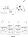
- FIG. 1 illustrates an exemplary 5G new radio (NR) network 100 supporting power control setting activation for uplink (UL) transmission in accordance with aspects of the current invention.
- the 5G NR network 100 includes a user equipment (UE) 110 communicatively connected to a gNB 121 operating in a licensed band (e.g., 30GHz ⁇ 300GHz for mmWave) of an access network 120 which provides radio access using a Radio Access Technology (RAT) (e.g., the 5G NR technology).
- RAT Radio Access Technology
- the access network 120 is connected to a 5G core network 130 by means of the NG interface, more specifically to a User Plane Function (UPF) by means of the NG user-plane part (NG-u), and to a Mobility Management Function (AMF) by means of the NG control-plane part (NGc).
- UPF User Plane Function
- AMF Mobility Management Function
- One gNB can be connected to multiple UPFs/AMFs for the purpose of load sharing and redundancy.
- the UE 110 may be a smart phone, a wearable device, an Internet of Things (IoT) device, and a tablet, etc.
- UE 110 may be a Notebook (NB) or Personal Computer (PC) inserted or installed with a data card which includes a modem and RF transceiver(s) to provide the functionality of wireless communication.
- the gNB 121 may provide communication coverage for a geographic coverage area in which communications with the UE 110 is supported via a communication link 101.
- the communication link 101 shown in the 5G NR network 100 may include UL transmissions from the UE 110 to the gNB 121 (e.g., on the Physical Uplink Control Channel (PUCCH) or Physical Uplink Shared Channel (PUSCH)) or downlink (DL) transmissions from the gNB 121 to the UE 110 (e.g., on the Physical Downlink Control Channel (PDCCH) or Physical Downlink Shared Channel (PDSCH)).
- PUCCH Physical Uplink Control Channel
- PUSCH Physical Uplink Shared Channel
- FIG. 2 is a simplified block diagram of the gNB 121 and the UE 110 in accordance with embodiments of the present invention.
- an antenna 197 transmits and receives radio signal.
- a radio frequency (RF) transceiver module 196 coupled with the antenna, receives RF signals from the antenna, converts them to baseband signals and sends them to processor 193.
- RF transceiver 196 also converts received baseband signals from the processor 193, converts them to RF signals, and sends out to antenna 197.
- Processor 193 processes the received baseband signals and invokes different functional modules and circuits to perform features in the gNB 121.
- Memory 192 stores program instructions and data 190 to control the operations of the gNB 121.
- antenna 177 transmits and receives RF signals.
- RF transceiver module 176 coupled with the antenna, receives RF signals from the antenna, converts them to baseband signals and sends them to processor 173.
- the RF transceiver 176 also converts received baseband signals from the processor 173, converts them to RF signals, and sends out to antenna 177.
- Processor 173 processes the received baseband signals and invokes different functional modules and circuits to perform features in the UE 110.
- Memory 172 stores program instructions and data 170 to control the operations of the UE 110.
- the gNB 121 and the UE 110 also include several functional modules and circuits that can be implemented and configured to perform embodiments of the present invention.
- the gNB 121 includes a set of control functional modules and circuit 180.
- Transmission configuration indication (TCI) handling circuit 182 handles TCI state(s) and associated network parameters for the UE 110.
- Configuration and control circuit 181 provides different parameters to configure and control the UE 110.
- the UE 110 includes a set of control functional modules and circuit 160.
- TCI handling circuit 162 handles TCI state(s) and associated network parameters.
- Configuration and control circuit 161 handles configuration and control parameters from the gNB 121.
- the different functional modules and circuits can be implemented and configured by software, firmware, hardware, and any combination thereof.
- the function modules and circuits when executed by the processors 193 and 173 (e.g., via executing program codes 190 and 170), allow the gNB 121 and the UE 110 to perform embodiments of the present invention.
- Figure 3 illustrates one embodiment of message transmissions in accordance with one novel aspect.
- the gNB 121 transmits an indication 1210 to the UE 110.
- the indication 1210 indicates a specific TCI state.
- the UE 110 receives the indication 1210 from the gNB 121.
- the UE 110 applies the specific TCI state for receptions corresponding to a control resource set (CORESET), which is associated with at least one search space (SS) set when: (1) the at least one SS set is configured with a first type; or (2) any of the at least one SS set is configured with a second type and the CORESET is configured to follow the specific TCI state.
- CORESET control resource set
- SS search space
- the first type includes UE-specific search space (USS), and the second type includes common search space (CSS).
- the at least one SS set includes an SS set '#X11' configured with USS and an SS set '#Y11' configured with USS.
- the CORESET includes a CORESET '#A11' which is associated with the SS sets '#X11' and '#Y11'.
- the specific TCI state includes a TCI state '#T11'.
- the UE 110 applies the TCI state '#T11' to the receptions which are: (1) physical downlink control channel (PDCCH) receptions; and (2) physical downlink shared channel (PDSCH) corresponding to the PDCCH receptions.
- receptions which are: (1) physical downlink control channel (PDCCH) receptions; and (2) physical downlink shared channel (PDSCH) corresponding to the PDCCH receptions.
- PDCCH physical downlink control channel
- PDSCH physical downlink shared channel
- the first type includes USS
- the second type includes CSS
- the at least one SS includes an SS set '#X12' configured with USS and an SS set '#Y12' configured with CSS.
- the CORESET (1) includes a CORESET '#A12' which is associated with the SS sets '#X12' and '#Y12'; and (2) is configured to follow unified TCI which is the specific TCI state.
- the specific TCI state includes a TCI state '#T12'.
- the UE 110 applies the TCI state '#T12' to: (1) PDCCH receptions; and (2) PDSCH corresponding to the PDCCH receptions.
- Figure 5 illustrates one embodiment of message transmissions in accordance with one novel aspect.
- the gNB 121 transmits a first configuration 1212, a second configuration 1214 and a third configuration 1216 to the UE 110.
- the UE 110 receives the first configuration 1212, the second configuration 1214 and the third configuration 1216 from the gNB 121.
- the first configuration 1212 configures at least one SS set to the UE 110.
- the second configuration 1214 configures a CORESET to the UE 110.
- the first configuration 1212 further associates the at least one SS set with the CORESET.
- the third configuration 1216 records a list of TCI states.
- the gNB 121 transmit an indication 1218 to the UE 110.
- the indication 1218 which may include an activation command (e.g., a media access control-control element (MAC-CE)) or a downlink control information (DCI), indicates a specific TCI state on the list of the TCI states.
- MAC-CE media access control-control element
- DCI downlink control information
- the UE 110 applies the specific TCI state for receptions corresponding to the CORESET when: (1) the at least one SS set is configured with only a first type; or (2) any of the at least one SS set is configured with a second type and the CORESET is configured to follow the specific TCI state according to a specific parameter in the second configuration 1214.
- the first type includes USS or Type3-PDCCH CSS (which is specified in 3GPP specification), and the second type includes CSS except Type3-PDCCH CSS.
- the at least one SS set includes an SS set '#X21' configured with USS and an SS set '#Y21' configured with Type3-PDCCH CSS.
- the CORESET includes a CORESET '#A21' which is associated with the SS sets '#X21' and '#Y21'.
- the specific TCI state includes a TCI state '#T21'.
- the UE 110 applies the TCI state '#T21' to the receptions which are: (1) PDCCH receptions; and (2) PDSCH corresponding to the PDCCH receptions.
- the UE 110 quasi co-locates a first demodulation reference signal (DM-RS) port and a second DM-RS port with at least one reference signal of the TCI state #T21'.
- the first DM-RS port is for the PDCCH receptions.
- the second DM-RS port is for the PDSCH receptions scheduled by DCI provided by the PDCCH receptions in the CORESET '#A21'.
- the first type includes USS or Type3-PDCCH CSS (which is specified in 3GPP specification), and the second type includes CSS except Type3-PDCCH CSS.
- the at least one SS includes an SS set '#X22' configured with USS and an SS set '#Y22' configured with CSS except Type3-PDCCH CSS.
- the CORESET (1) includes a CORESET '#A22' which is associated with the SS sets '#X22' and '#Y22'; and (2) is configured to follow unified TCI, which is the specific TCI state, according to the specific parameter in the second configuration 1214.
- the specific TCI state includes a TCI state '#T22'.
- the UE 110 applies the TCI state '#T22' to: (1) PDCCH receptions; and (2) PDSCH corresponding to the PDCCH receptions.
- the UE 110 quasi co-locates a first DM-RS port and a second DM-RS port with at least one reference signal of the TCI state #T22'.
- the first DM-RS port is for the PDCCH receptions.
- the second DM-RS port is for the PDSCH receptions scheduled by DCI provided by the PDCCH receptions in the CORESET '#A22'.
- Figure 7 illustrates one embodiment of message transmissions in accordance with one novel aspect.
- the gNB 121 transmits a radio resource control (RRC) configuration 1220 to the UE 110.
- the RRC configuration 1220 indicates to the UE 110 multiple TCI states.
- the gNB 121 transmits an activation command 1222 (e.g., a MAC-CE) to the UE 110.
- the activation command 1222 is used for the UE 110 to activate a subset of the multiple TCI states.
- the activation command 1222 indicates to the UE 110 an index of a CORESET pool.
- the UE 110 applies the only one activated TCI state as the specific TCI state to DM-RS ports of PDCCH and PDSCH.
- the gNB 121 transmits an indication 1224 (e.g., a DCI) to the UE 110.
- the indication 1224 indicates to the UE 110 at least one TCI state of the activated TCI states as the specific TCI state.
- the UE 110 applies the specific TCI state to DM-RS ports of PDCCH and PDSCH.
- the UE 110 applies the specific TCI state for receptions corresponding to a CORESET that belongs to the CORESET pool.
- the UE 110 applies the specific TCI state for receptions corresponding to a CORESET that belongs to the CORESET pool and is associated with at least one SS set when: (1) the at least one SS set is configured with a first type; or (2) any of the at least one SS set is configured with a second type and the CORESET is configured to follow the specific TCI state.
- the receptions corresponding to a CORESET includes (1) PDCCH receptions on the CORESET; and (2) PDSCH receptions corresponding to the PDCCH receptions on the CORESET.
- the first type includes USS, and the second type includes CSS.
- the first type includes USS or Type3-PDCCH CSS, and the second type includes CSS except Type3-PDCCH CSS.
- FIG. 8 is a flow chart of a method of applying TCI state in accordance with one novel aspect.
- a UE receives an indication of a specific TCI state from a network.
- the UE applies the specific TCI state for receptions corresponding to a CORESET associated with at least one SS set when: (1) the at least one SS set is configured with a first type; or (2) any of the at least one SS set is configured with a second type and the CORESET is configured to follow the specific TCI state.
- the first type includes USS, and the second type includes CSS.
- the first type includes USS or Type3-PDCCH CSS, and the second type includes CSS except Type3-PDCCH CSS.
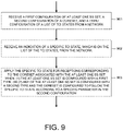
- FIG. 9 is a flow chart of a method of applying TCI state in accordance with one novel aspect.
- a UE receives a first configuration of at least one SS set, a second configuration of a CORESET, and a third configuration of a list of TCI states from a network.
- the CORESET is associated with the at least one SS set according to the first configuration.
- the UE receives an indication of a specific TCI state, which is on the list of the TCI states, from the network.
- the UE applies the specific TCI state for receptions corresponding to the CORESET associated with the at least one SS set when: (1) the at least one SS set is configured with a first type; or (2) any of the at least one SS set is configured with a second type and the CORESET is configured to follow the specific TCI state according to a specific parameter in the second configuration.
- the indication includes an activation command (e.g., a MAC-CE) or a DCI.
- the first type includes USS
- the second type includes CSS.
- the first type includes USS or Type3-PDCCH CSS
- the second type includes CSS except Type3-PDCCH CSS.
- operation of applying the specific TCI state for the receptions in step 903 includes operation of applying the specific TCI state to PDCCH receptions and PDSCH receptions corresponding to the PDCCH receptions. More specifically, operation of applying the specific TCI state for the receptions in step 903 includes quasi co-locating a first DM-RS port and a second DM-RS port with at least one reference signal of the specific TCI state while the first DM-RS port is for PDCCH receptions and the second DM-RS port is for PDSCH receptions corresponding to the PDCCH receptions.
Landscapes
- Engineering & Computer Science (AREA)
- Signal Processing (AREA)
- Computer Networks & Wireless Communication (AREA)
- Mobile Radio Communication Systems (AREA)
- Two-Way Televisions, Distribution Of Moving Picture Or The Like (AREA)
- Forging (AREA)
- Telephone Function (AREA)
- User Interface Of Digital Computer (AREA)
Abstract
Description
- This application claims the benefit under 35 U.S.C. §119 from
U.S. provisional application serial number 63/226,806, entitled "Transmission Configuration Indication for PDCCH and PDSCH," filed on July 29, 2021 U.S. Provisional Application Number 63/275,981, entitled "Transmission Configuration Indication for PDCCH and PDSCH," filed on November 5, 2021 - The disclosed embodiments relate generally to wireless communication, and, more particularly, to method and user equipment for transmission configuration indication (TCI) state application.
- In conventional network of 3rd generation partnership project (3GPP) 5G new radio (NR), the user equipment (UE) can be configured, by the base station (BS), with: (1) one or more control resource sets (CORESETs); (2) one or more search space sets; and (3) a plurality of transmission configuration indication (TCI) states. The BS can transmit an activation command to the UE for the UE to apply at least one of the TCI states. However, some details of applying the at least one of the TCI states have not been determined and need to be further discussed.
- Method and user equipment (UE) are provided for transmission configuration indication (TCI) state application and are defined in the independent claims. The dependent claims define preferred embodiments thereof. In particular, a UE can receive an indication of a specific TCI state from a network. Then the UE can apply the specific TCI state for receptions corresponding to a control resource set (CORESET) associated with at least one search space set when: (1) the at least one search space set is configured with a first type; or (2) any of the at least one search space set is configured with a second type and the CORESET is configured to follow the specific TCI state.
- Other embodiments and advantages are described in the detailed description below. This summary does not purport to define the invention. The invention is defined by the claims.
- The accompanying drawings, where like numerals indicate like components, illustrate embodiments of the invention.
-
Figure 1 illustrates an exemplary 5G new radio network supporting power control setting activation for uplink transmission in accordance with embodiments of the current invention. -
Figure 2 is a simplified block diagram of the gNB and the UE in accordance with embodiments of the current invention. -
Figure 3 illustrates one embodiment of message transmissions in accordance with embodiments of the current invention. -
Figure 4A illustrates an example of associations among at least one SS set, a CORESET and at least one transmission in accordance with embodiments of the current invention. -
Figure 4B illustrates an example of associations among at least one SS set, a CORESET and at least one transmission in accordance with embodiments of the current invention. -
Figure 5 illustrates one embodiment of message transmissions in accordance with embodiments of the current invention. -
Figure 6A illustrates an example of associations among at least one SS set, a CORESET and at least one transmission in accordance with embodiments of the current invention. -
Figure 6B illustrates an example of associations among at least one SS set, a CORESET and at least one transmission in accordance with embodiments of the current invention. -
Figure 7 is a flow chart of a method of applying TCI state in accordance with embodiments of the current invention. -
Figure 8 is a flow chart of a method of applying TCI state in accordance with embodiments of the current invention. -
Figure 9 is a flow chart of a method of applying TCI state in accordance with one novel aspect. - Reference will now be made in detail to some embodiments of the invention, examples of which are illustrated in the accompanying drawings.
-
Figure 1 illustrates an exemplary 5G new radio (NR)network 100 supporting power control setting activation for uplink (UL) transmission in accordance with aspects of the current invention. The 5G NRnetwork 100 includes a user equipment (UE) 110 communicatively connected to a gNB 121 operating in a licensed band (e.g., 30GHz~300GHz for mmWave) of anaccess network 120 which provides radio access using a Radio Access Technology (RAT) (e.g., the 5G NR technology). Theaccess network 120 is connected to a 5G core network 130 by means of the NG interface, more specifically to a User Plane Function (UPF) by means of the NG user-plane part (NG-u), and to a Mobility Management Function (AMF) by means of the NG control-plane part (NGc). One gNB can be connected to multiple UPFs/AMFs for the purpose of load sharing and redundancy. The UE 110 may be a smart phone, a wearable device, an Internet of Things (IoT) device, and a tablet, etc. Alternatively, UE 110 may be a Notebook (NB) or Personal Computer (PC) inserted or installed with a data card which includes a modem and RF transceiver(s) to provide the functionality of wireless communication. - The gNB 121 may provide communication coverage for a geographic coverage area in which communications with the UE 110 is supported via a
communication link 101. Thecommunication link 101 shown in the5G NR network 100 may include UL transmissions from the UE 110 to the gNB 121 (e.g., on the Physical Uplink Control Channel (PUCCH) or Physical Uplink Shared Channel (PUSCH)) or downlink (DL) transmissions from the gNB 121 to the UE 110 (e.g., on the Physical Downlink Control Channel (PDCCH) or Physical Downlink Shared Channel (PDSCH)). -
Figure 2 is a simplified block diagram of thegNB 121 and theUE 110 in accordance with embodiments of the present invention. For the gNB 121, anantenna 197 transmits and receives radio signal. A radio frequency (RF)transceiver module 196, coupled with the antenna, receives RF signals from the antenna, converts them to baseband signals and sends them toprocessor 193.RF transceiver 196 also converts received baseband signals from theprocessor 193, converts them to RF signals, and sends out toantenna 197.Processor 193 processes the received baseband signals and invokes different functional modules and circuits to perform features in the gNB 121.Memory 192 stores program instructions anddata 190 to control the operations of the gNB 121. - Similarly, for the UE 110,
antenna 177 transmits and receives RF signals.RF transceiver module 176, coupled with the antenna, receives RF signals from the antenna, converts them to baseband signals and sends them toprocessor 173. TheRF transceiver 176 also converts received baseband signals from theprocessor 173, converts them to RF signals, and sends out toantenna 177.Processor 173 processes the received baseband signals and invokes different functional modules and circuits to perform features in the UE 110.Memory 172 stores program instructions anddata 170 to control the operations of the UE 110. - The gNB 121 and the UE 110 also include several functional modules and circuits that can be implemented and configured to perform embodiments of the present invention. In the example of
figure 2 , the gNB 121 includes a set of control functional modules andcircuit 180. Transmission configuration indication (TCI)handling circuit 182 handles TCI state(s) and associated network parameters for the UE 110. Configuration and control circuit 181 provides different parameters to configure and control the UE 110. The UE 110 includes a set of control functional modules andcircuit 160.TCI handling circuit 162 handles TCI state(s) and associated network parameters. Configuration and control circuit 161 handles configuration and control parameters from the gNB 121. - Note that the different functional modules and circuits can be implemented and configured by software, firmware, hardware, and any combination thereof. The function modules and circuits, when executed by the
processors 193 and 173 (e.g., via executingprogram codes 190 and 170), allow the gNB 121 and the UE 110 to perform embodiments of the present invention. -
Figure 3 illustrates one embodiment of message transmissions in accordance with one novel aspect. In particular, the gNB 121 transmits anindication 1210 to the UE 110. Theindication 1210 indicates a specific TCI state. The UE 110 receives theindication 1210 from the gNB 121. Then, the UE 110 applies the specific TCI state for receptions corresponding to a control resource set (CORESET), which is associated with at least one search space (SS) set when: (1) the at least one SS set is configured with a first type; or (2) any of the at least one SS set is configured with a second type and the CORESET is configured to follow the specific TCI state. - Please refer to
figure 4A , which is an example of associations among the at least one SS set, the CORESET and the receptions. In detail, the first type includes UE-specific search space (USS), and the second type includes common search space (CSS). The at least one SS set includes an SS set '#X11' configured with USS and an SS set '#Y11' configured with USS. The CORESET includes a CORESET '#A11' which is associated with the SS sets '#X11' and '#Y11'. The specific TCI state includes a TCI state '#T11'. - Accordingly, because the SS sets '#X11' and '#Y11' are all configured with USS, the
UE 110 applies the TCI state '#T11' to the receptions which are: (1) physical downlink control channel (PDCCH) receptions; and (2) physical downlink shared channel (PDSCH) corresponding to the PDCCH receptions. - Please refer to
figure 4B , which is an example of associations among the at least one SS set, the CORESET and the receptions. In detail, the first type includes USS, and the second type includes CSS. The at least one SS includes an SS set '#X12' configured with USS and an SS set '#Y12' configured with CSS. The CORESET: (1) includes a CORESET '#A12' which is associated with the SS sets '#X12' and '#Y12'; and (2) is configured to follow unified TCI which is the specific TCI state. The specific TCI state includes a TCI state '#T12'. - Accordingly, because: (1) one of the SS sets '#X12' and '#Y12' is configured with CSS; and (2) the CORESET '#A12' is configured to follow the specific TCI state, the
UE 110 applies the TCI state '#T12' to: (1) PDCCH receptions; and (2) PDSCH corresponding to the PDCCH receptions. -
Figure 5 illustrates one embodiment of message transmissions in accordance with one novel aspect. In particular, thegNB 121 transmits a first configuration 1212, a second configuration 1214 and a third configuration 1216 to theUE 110. TheUE 110 receives the first configuration 1212, the second configuration 1214 and the third configuration 1216 from thegNB 121. - The first configuration 1212 configures at least one SS set to the
UE 110. The second configuration 1214 configures a CORESET to theUE 110. The first configuration 1212 further associates the at least one SS set with the CORESET. The third configuration 1216 records a list of TCI states. - The
gNB 121 transmit an indication 1218 to theUE 110. The indication 1218, which may include an activation command (e.g., a media access control-control element (MAC-CE)) or a downlink control information (DCI), indicates a specific TCI state on the list of the TCI states. Then, theUE 110 applies the specific TCI state for receptions corresponding to the CORESET when: (1) the at least one SS set is configured with only a first type; or (2) any of the at least one SS set is configured with a second type and the CORESET is configured to follow the specific TCI state according to a specific parameter in the second configuration 1214. - Please refer to
figure 6A , which is an example of associations among the at least one SS set, the CORESET and the receptions. In detail, the first type includes USS or Type3-PDCCH CSS (which is specified in 3GPP specification), and the second type includes CSS except Type3-PDCCH CSS. The at least one SS set includes an SS set '#X21' configured with USS and an SS set '#Y21' configured with Type3-PDCCH CSS. The CORESET includes a CORESET '#A21' which is associated with the SS sets '#X21' and '#Y21'. The specific TCI state includes a TCI state '#T21'. - Accordingly, because the SS sets '#X21' and '#Y21' are all configured with USS or Type3-PDCCH CSS, the
UE 110 applies the TCI state '#T21' to the receptions which are: (1) PDCCH receptions; and (2) PDSCH corresponding to the PDCCH receptions. - More specifically, the
UE 110 quasi co-locates a first demodulation reference signal (DM-RS) port and a second DM-RS port with at least one reference signal of the TCI state #T21'. The first DM-RS port is for the PDCCH receptions. The second DM-RS port is for the PDSCH receptions scheduled by DCI provided by the PDCCH receptions in the CORESET '#A21'. - Please refer to
figure 6B , which is an example of associations among the at least one SS set, the CORESET and the receptions. In detail, the first type includes USS or Type3-PDCCH CSS (which is specified in 3GPP specification), and the second type includes CSS except Type3-PDCCH CSS. The at least one SS includes an SS set '#X22' configured with USS and an SS set '#Y22' configured with CSS except Type3-PDCCH CSS. The CORESET: (1) includes a CORESET '#A22' which is associated with the SS sets '#X22' and '#Y22'; and (2) is configured to follow unified TCI, which is the specific TCI state, according to the specific parameter in the second configuration 1214. The specific TCI state includes a TCI state '#T22'. - Accordingly, because: (1) one of the SS sets '#X22' and '#Y22' is configured with CSS except Type3-PDCCH CSS; and (2) the CORESET '#A22' is configured to follow the specific TCI state according to the specific parameter in the second configuration 1214, the
UE 110 applies the TCI state '#T22' to: (1) PDCCH receptions; and (2) PDSCH corresponding to the PDCCH receptions. - More specifically, the
UE 110 quasi co-locates a first DM-RS port and a second DM-RS port with at least one reference signal of the TCI state #T22'. The first DM-RS port is for the PDCCH receptions. The second DM-RS port is for the PDSCH receptions scheduled by DCI provided by the PDCCH receptions in the CORESET '#A22'. -
Figure 7 illustrates one embodiment of message transmissions in accordance with one novel aspect. In particular, thegNB 121 transmits a radio resource control (RRC) configuration 1220 to theUE 110. The RRC configuration 1220 indicates to theUE 110 multiple TCI states. ThegNB 121 transmits an activation command 1222 (e.g., a MAC-CE) to theUE 110. The activation command 1222 is used for theUE 110 to activate a subset of the multiple TCI states. The activation command 1222 indicates to theUE 110 an index of a CORESET pool. - Preferably, when the activation command 1222 is used for the
UE 110 to activate only one of the multiple TCI states, theUE 110 applies the only one activated TCI state as the specific TCI state to DM-RS ports of PDCCH and PDSCH. - Preferably, when the activation command 1222 is used for the
UE 110 to activate more than one of the multiple TCI states, thegNB 121 transmits an indication 1224 (e.g., a DCI) to theUE 110. The indication 1224 indicates to theUE 110 at least one TCI state of the activated TCI states as the specific TCI state. TheUE 110 applies the specific TCI state to DM-RS ports of PDCCH and PDSCH. - Preferably, the
UE 110 applies the specific TCI state for receptions corresponding to a CORESET that belongs to the CORESET pool. Preferably, theUE 110 applies the specific TCI state for receptions corresponding to a CORESET that belongs to the CORESET pool and is associated with at least one SS set when: (1) the at least one SS set is configured with a first type; or (2) any of the at least one SS set is configured with a second type and the CORESET is configured to follow the specific TCI state. - Preferably, the receptions corresponding to a CORESET includes (1) PDCCH receptions on the CORESET; and (2) PDSCH receptions corresponding to the PDCCH receptions on the CORESET.
- In some implementations, the first type includes USS, and the second type includes CSS. In some implementations, the first type includes USS or Type3-PDCCH CSS, and the second type includes CSS except Type3-PDCCH CSS.
-
Figure 8 is a flow chart of a method of applying TCI state in accordance with one novel aspect. Instep 801, a UE receives an indication of a specific TCI state from a network. Instep 802, the UE applies the specific TCI state for receptions corresponding to a CORESET associated with at least one SS set when: (1) the at least one SS set is configured with a first type; or (2) any of the at least one SS set is configured with a second type and the CORESET is configured to follow the specific TCI state. - In one implementation, the first type includes USS, and the second type includes CSS. In one implementation, the first type includes USS or Type3-PDCCH CSS, and the second type includes CSS except Type3-PDCCH CSS.
-
Figure 9 is a flow chart of a method of applying TCI state in accordance with one novel aspect. Instep 901, a UE receives a first configuration of at least one SS set, a second configuration of a CORESET, and a third configuration of a list of TCI states from a network. The CORESET is associated with the at least one SS set according to the first configuration. - In
step 902, the UE receives an indication of a specific TCI state, which is on the list of the TCI states, from the network. Instep 903, the UE applies the specific TCI state for receptions corresponding to the CORESET associated with the at least one SS set when: (1) the at least one SS set is configured with a first type; or (2) any of the at least one SS set is configured with a second type and the CORESET is configured to follow the specific TCI state according to a specific parameter in the second configuration. - In one implementation, the indication includes an activation command (e.g., a MAC-CE) or a DCI. In one implementation, the first type includes USS, and the second type includes CSS. In one implementation, the first type includes USS or Type3-PDCCH CSS, and the second type includes CSS except Type3-PDCCH CSS.
- In one implementation, operation of applying the specific TCI state for the receptions in
step 903 includes operation of applying the specific TCI state to PDCCH receptions and PDSCH receptions corresponding to the PDCCH receptions. More specifically, operation of applying the specific TCI state for the receptions instep 903 includes quasi co-locating a first DM-RS port and a second DM-RS port with at least one reference signal of the specific TCI state while the first DM-RS port is for PDCCH receptions and the second DM-RS port is for PDSCH receptions corresponding to the PDCCH receptions. - Although the present invention has been described in connection with certain specific embodiments for instructional purposes, the present invention is not limited thereto. Accordingly, various modifications, adaptations, and combinations of various features of the described embodiments can be practiced without departing from the scope of the invention as set forth in the claims.
Claims (15)
- A method, comprising:receiving, by a user equipment, in the following also referred to as UE, an indication of a specific transmission configuration indication, in the following also referred to as TCI, state from a network (801; 902); andapplying, by the UE, the specific TCI state for receptions corresponding to a control resource set, in the following also referred to as CORESET, associated with at least one search space set when:the at least one search space set is configured with a first type, orany of the at least one search space set is configured with a second type and the CORESET is configured to follow the specific TCI state (802; 903).
- The method of claim 1, further comprising:
receiving, by the UE, a first configuration of the at least one search space set from the network (901), wherein the CORESET is associated with the at least one search space set according to the first configuration. - The method of claim 2, further comprising:
receiving, by the UE, a second configuration of the CORESET from the network (901). - The method of claim 3, wherein the CORESET is configured to follow the specific TCI state according to a specific parameter in the second configuration.
- The method of any one of claims 1 to 4, further comprising,receiving, by the UE, a configuration of a list of TCI states (901),wherein the specific TCI state is on the list of the TCI states.
- The method of any one of claims 1 to 5, wherein the first type includes UE-specific search space or Type3-physical downlink control channel common search space, in the following also referred to as Type3-PDCCH CSS, and the second type includes common search space, in the following also referred to as CSS, except Type3-PDCCH CSS.
- The method of any one of claims 1 to 6, wherein the step of applying the specific TCI state for the receptions corresponding to the CORESET includes:
applying, by the UE, the specific TCI state to physical downlink control channel, in the following also referred to as PDCCH, receptions and physical downlink shared channel, in the following also referred to as PDSCH, receptions corresponding to the PDCCH receptions. - The method of any one of claims 1 to 7, wherein the step of applying the specific TCI state for the receptions corresponding to the CORESET includes:
quasi co-locating, by the UE, a first demodulation reference signal, in the following also referred to as DM-RS, port and a second DM-RS port with at least one reference signal of the specific TCI state, wherein the first DM-RS port is for PDCCH receptions and the second DM-RS port is for PDSCH receptions corresponding to the PDCCH receptions. - A user equipment, in the following also referred to as UE, (110) comprising:a transceiver (176) that receives an indication of a specific transmission configuration indication, in the following also referred to as TCI, state from a network (121); anda TCI handling circuit (162) that applies the specific TCI state for receptions corresponding to a control resource set, in the following also referred to as CORESET, associated with at least one search space set when:the at least one search space set is configured with a first type, orany of the at least one search space set is configured with a second type and the CORESET is configured to follow the specific TCI state.
- The UE (110) of claim 9, wherein the transceiver (176) further receives a first configuration of the at least one search space set from the network, and the CORESET is associated with the at least one search space set according to the first configuration.
- The UE (110) of claim 10, wherein the transceiver (176) further receives a second configuration of the CORESET from the network.
- The UE (110) of any one of claims 9 to 11, wherein the transceiver (176) further receives a third configuration of a list of TCI states, and the specific TCI state is on the list of the TCI states.
- The UE (110) of any one of claims 9 to 12, wherein the first type includes UE-specific search space or Type3-physical downlink control channel common search space, in the following also referred to as Type3-PDCCH CSS, and the second type includes common search space, in the following also referred to as CSS, except Type3-PDCCH CSS.
- The UE (110) of any one of claims 9 to 13, wherein the TCI handling circuit (162) further applies the specific TCI state to physical downlink control channel, in the following also referred to as PDCCH, receptions and physical downlink shared channel, in the following also referred to as PDSCH, receptions corresponding to the PDCCH receptions.
- The UE (110) of any one of claims 9 to 14, wherein the TCI handling circuit (162) further quasi co-locates a first demodulation reference signal, in the following also referred to as DM-RS, port and a second DM-RS port with at least one reference signal of the specific TCI state, the first DM-RS port is for PDCCH receptions, and the second DM-RS port is for PDSCH receptions corresponding to the PDCCH receptions.
Applications Claiming Priority (3)
| Application Number | Priority Date | Filing Date | Title |
|---|---|---|---|
| US202163226806P | 2021-07-29 | 2021-07-29 | |
| US202163275981P | 2021-11-05 | 2021-11-05 | |
| US17/840,891 US12526798B2 (en) | 2021-07-29 | 2022-06-15 | Method and user equipment for transmission configuration indication (TCI) state application |
Publications (1)
| Publication Number | Publication Date |
|---|---|
| EP4125235A1 true EP4125235A1 (en) | 2023-02-01 |
Family
ID=82786380
Family Applications (1)
| Application Number | Title | Priority Date | Filing Date |
|---|---|---|---|
| EP22187783.0A Pending EP4125235A1 (en) | 2021-07-29 | 2022-07-29 | Method and user equipment for transmission configuration indication (tci) state application |
Country Status (4)
| Country | Link |
|---|---|
| US (1) | US12526798B2 (en) |
| EP (1) | EP4125235A1 (en) |
| CN (1) | CN115694761B (en) |
| TW (1) | TWI816490B (en) |
Citations (4)
| Publication number | Priority date | Publication date | Assignee | Title |
|---|---|---|---|---|
| US20190141693A1 (en) * | 2017-11-08 | 2019-05-09 | Samsung Electronics Co., Ltd | Method and apparatus for beam management in the unlicensed spectrum |
| WO2019214383A1 (en) * | 2018-05-11 | 2019-11-14 | 中国移动通信有限公司研究院 | Quasi co-location information configuration method, network device and user equipment |
| WO2019244223A1 (en) * | 2018-06-18 | 2019-12-26 | 株式会社Nttドコモ | User terminal and wireless communication method |
| EP3641461A1 (en) * | 2018-05-17 | 2020-04-22 | LG Electronics Inc. -1- | Method for determining transmission configuration indicator for terminal in wireless communication system and device using same method |
Family Cites Families (20)
| Publication number | Priority date | Publication date | Assignee | Title |
|---|---|---|---|---|
| JP2020014082A (en) | 2018-07-17 | 2020-01-23 | シャープ株式会社 | Base station device, terminal device, communication method, and integrated circuit |
| EP3876665A4 (en) * | 2018-11-01 | 2022-06-22 | NTT DoCoMo, Inc. | USER DEVICE AND BASE STATION DEVICE |
| US11172513B2 (en) | 2018-11-12 | 2021-11-09 | Qualcomm Incorporated | Configuring transmission configuration indication states on an initial control resource set |
| CN111245488A (en) * | 2018-11-28 | 2020-06-05 | 索尼公司 | Electronic device, communication method and storage medium |
| WO2020122685A1 (en) * | 2018-12-13 | 2020-06-18 | 엘지전자 주식회사 | Method for transmitting and receiving data in wireless communication system and apparatus therefor |
| EP4221027A1 (en) * | 2018-12-13 | 2023-08-02 | Lg Electronics, Inc. | Method for transmitting and receiving data in wireless communication system and apparatus therefor |
| US11405152B2 (en) * | 2019-01-11 | 2022-08-02 | Qualcomm Incorporated | QCL relationship and/or DMRS port identification |
| US12119897B2 (en) * | 2019-04-08 | 2024-10-15 | Lg Electronics Inc. | Apparatus and method for reporting channel state information in wireless communication system |
| US10911284B1 (en) * | 2019-07-16 | 2021-02-02 | Microsoft Technology Licensing, Llc | Intelligent optimization of communication systems utilizing error correction |
| US11411791B2 (en) | 2019-07-19 | 2022-08-09 | Qualcomm Incorporated | Intra-symbol multiplexing with a single carrier waveform |
| US12219557B2 (en) * | 2019-11-05 | 2025-02-04 | Comcast Cable Communications, Llc | Wireless communications for scheduling transmissions |
| WO2021162334A1 (en) * | 2020-02-10 | 2021-08-19 | 엘지전자 주식회사 | Method and device for transmitting or receiving downlink channel from multiple transmission reception points in wireless communication system |
| CN115943701B (en) * | 2020-07-31 | 2026-02-03 | 联想(北京)有限公司 | Method and apparatus for downlink transmission in a physical downlink control channel |
| BR112023002106A2 (en) * | 2020-08-05 | 2023-04-18 | Interdigital Patent Holdings Inc | WIRELESS TRANSMISSION/RECEIVER UNIT, AND, METHOD IMPLEMENTED IN A WIRELESS TRANSMISSION/RECEIVER UNIT |
| WO2022030869A1 (en) * | 2020-08-06 | 2022-02-10 | 엘지전자 주식회사 | Method for performing channel access procedure and apparatus therefor |
| KR20220046323A (en) * | 2020-10-07 | 2022-04-14 | 삼성전자주식회사 | Method and apparatus for cross-slot scheduling in a wireless communication system |
| US11991621B2 (en) * | 2020-10-13 | 2024-05-21 | Ofinno, Llc | Beam update for control resource sets |
| US11785536B2 (en) * | 2021-01-04 | 2023-10-10 | Samsung Electronics Co., Ltd. | Scheduling for a UE capable of receptions over multiple antenna panels |
| US20240089061A1 (en) * | 2021-01-15 | 2024-03-14 | Telefonaktiebolaget Lm Ericsson (Publ) | Systems and methods for linking pdcch candidates |
| US12368560B2 (en) * | 2021-10-15 | 2025-07-22 | Samsung Electronics Co., Ltd. | Method and apparatus for configuring a unified TCI state |
-
2022
- 2022-06-15 US US17/840,891 patent/US12526798B2/en active Active
- 2022-07-12 CN CN202210818403.1A patent/CN115694761B/en active Active
- 2022-07-28 TW TW111128301A patent/TWI816490B/en active
- 2022-07-29 EP EP22187783.0A patent/EP4125235A1/en active Pending
Patent Citations (4)
| Publication number | Priority date | Publication date | Assignee | Title |
|---|---|---|---|---|
| US20190141693A1 (en) * | 2017-11-08 | 2019-05-09 | Samsung Electronics Co., Ltd | Method and apparatus for beam management in the unlicensed spectrum |
| WO2019214383A1 (en) * | 2018-05-11 | 2019-11-14 | 中国移动通信有限公司研究院 | Quasi co-location information configuration method, network device and user equipment |
| EP3641461A1 (en) * | 2018-05-17 | 2020-04-22 | LG Electronics Inc. -1- | Method for determining transmission configuration indicator for terminal in wireless communication system and device using same method |
| WO2019244223A1 (en) * | 2018-06-18 | 2019-12-26 | 株式会社Nttドコモ | User terminal and wireless communication method |
Non-Patent Citations (4)
| Title |
|---|
| ERICSSON: "On common beam for PDSCH and PDCCH", vol. RAN WG1, no. Prague, Czech Republic; 20171009 - 20171013, 3 October 2017 (2017-10-03), XP051353234, Retrieved from the Internet <URL:http://www.3gpp.org/ftp/tsg_ran/WG1_RL1/TSGR1_90b/Docs/> [retrieved on 20171003] * |
| MEDIATEK INC: "Remaining issues on Rel-17 multi-beam operation", vol. RAN WG1, no. e-Meeting; 20220211 - 20220219, 14 February 2022 (2022-02-14), XP052109984, Retrieved from the Internet <URL:https://ftp.3gpp.org/tsg_ran/WG1_RL1/TSGR1_108-e/Docs/R1-2202057.zip R1-2202057_MB_final.docx> [retrieved on 20220214] * |
| MEDIATEK INC: "Summary 2 on Remaing issues on Beam Failure Recovery Document for discussion", vol. RAN WG1, no. Busan, Korea; 20180521 - 20180525, 24 May 2018 (2018-05-24), pages 1 - 29, XP051463405, Retrieved from the Internet <URL:http://www.3gpp.org/ftp/tsg%5Fran/WG1%5FRL1/TSGR1%5F93/Docs> [retrieved on 20180524] * |
| NTT DOCOMO ET AL: "Offline summary for PDCCH structure and search space part 2", vol. RAN WG1, no. Chengdu, China; 20181008 - 20181012, 9 October 2018 (2018-10-09), pages 1 - 66, XP051519250, Retrieved from the Internet <URL:http://www.3gpp.org/ftp/tsg%5Fran/WG1%5FRL1/TSGR1%5F94b/Docs/R1%2D1811926%2Ezip> [retrieved on 20181009] * |
Also Published As
| Publication number | Publication date |
|---|---|
| TWI816490B (en) | 2023-09-21 |
| US20230034356A1 (en) | 2023-02-02 |
| US12526798B2 (en) | 2026-01-13 |
| TW202306412A (en) | 2023-02-01 |
| CN115694761B (en) | 2025-08-19 |
| CN115694761A (en) | 2023-02-03 |
Similar Documents
| Publication | Publication Date | Title |
|---|---|---|
| US11540267B2 (en) | DCI detection method, PDCCH configuration method, and communications apparatus | |
| EP3624506A1 (en) | Communication method and apparatus | |
| US20230050894A1 (en) | Method and user equipment for pdcch paging early indication detection | |
| US12526817B2 (en) | Method for monitoring TCI field of DCI format | |
| US12532371B2 (en) | Downlink reception with multiple TCI states | |
| WO2024007832A1 (en) | Method and user equipment for applying timing advance command for multiple transmission reception points | |
| US20220231801A1 (en) | Apparatus and method for configuring application of tci state to component carriers | |
| US12267265B2 (en) | Apparatus and method for configuring application of TCI state to reference signal | |
| US12526798B2 (en) | Method and user equipment for transmission configuration indication (TCI) state application | |
| US20230344593A1 (en) | Apparatus and method for beam management in a multi-beam system | |
| US12082184B2 (en) | TCI state activation for downlink transmission and uplink transmission | |
| WO2025171632A1 (en) | Physical downlink control channel (pdcch) repetitions for system information transmissions in wireless networks | |
| WO2022028414A1 (en) | Power control setting activation for uplink transmission | |
| US20240322972A1 (en) | Method and user equipment for transmission configuration indication for multiple transmission reception points | |
| US20230170960A1 (en) | Method and base station for beam alignment | |
| EP4383638A2 (en) | Tci state indication for pusch transmission | |
| EP4175192A1 (en) | Apparatus and method for beam failure recovery in mobile communications |
Legal Events
| Date | Code | Title | Description |
|---|---|---|---|
| PUAI | Public reference made under article 153(3) epc to a published international application that has entered the european phase |
Free format text: ORIGINAL CODE: 0009012 |
|
| STAA | Information on the status of an ep patent application or granted ep patent |
Free format text: STATUS: THE APPLICATION HAS BEEN PUBLISHED |
|
| AK | Designated contracting states |
Kind code of ref document: A1 Designated state(s): AL AT BE BG CH CY CZ DE DK EE ES FI FR GB GR HR HU IE IS IT LI LT LU LV MC MK MT NL NO PL PT RO RS SE SI SK SM TR |
|
| P01 | Opt-out of the competence of the unified patent court (upc) registered |
Effective date: 20230607 |
|
| STAA | Information on the status of an ep patent application or granted ep patent |
Free format text: STATUS: REQUEST FOR EXAMINATION WAS MADE |
|
| 17P | Request for examination filed |
Effective date: 20230731 |
|
| RBV | Designated contracting states (corrected) |
Designated state(s): AL AT BE BG CH CY CZ DE DK EE ES FI FR GB GR HR HU IE IS IT LI LT LU LV MC MK MT NL NO PL PT RO RS SE SI SK SM TR |
|
| STAA | Information on the status of an ep patent application or granted ep patent |
Free format text: STATUS: EXAMINATION IS IN PROGRESS |
|
| 17Q | First examination report despatched |
Effective date: 20240516 |