EP4125179A1 - Backup power-supply device - Google Patents
Backup power-supply device Download PDFInfo
- Publication number
- EP4125179A1 EP4125179A1 EP22186520.7A EP22186520A EP4125179A1 EP 4125179 A1 EP4125179 A1 EP 4125179A1 EP 22186520 A EP22186520 A EP 22186520A EP 4125179 A1 EP4125179 A1 EP 4125179A1
- Authority
- EP
- European Patent Office
- Prior art keywords
- electronic device
- capacitor
- power supply
- switch
- turned
- Prior art date
- Legal status (The legal status is an assumption and is not a legal conclusion. Google has not performed a legal analysis and makes no representation as to the accuracy of the status listed.)
- Granted
Links
Images



Classifications
-
- H—ELECTRICITY
- H02—GENERATION; CONVERSION OR DISTRIBUTION OF ELECTRIC POWER
- H02J—ELECTRIC POWER NETWORKS; CIRCUIT ARRANGEMENTS OR SYSTEMS FOR SUPPLYING OR DISTRIBUTING ELECTRIC POWER; SYSTEMS FOR STORING ELECTRIC ENERGY
- H02J9/00—Circuit arrangements for emergency or stand-by power supply, e.g. for emergency lighting
- H02J9/04—Circuit arrangements for emergency or stand-by power supply, e.g. for emergency lighting in which the distribution system is disconnected from the normal source and connected to a standby source
- H02J9/06—Circuit arrangements for emergency or stand-by power supply, e.g. for emergency lighting in which the distribution system is disconnected from the normal source and connected to a standby source with automatic change-over, e.g. UPS systems
- H02J9/061—Circuit arrangements for emergency or stand-by power supply, e.g. for emergency lighting in which the distribution system is disconnected from the normal source and connected to a standby source with automatic change-over, e.g. UPS systems for DC powered loads
-
- B—PERFORMING OPERATIONS; TRANSPORTING
- B60—VEHICLES IN GENERAL
- B60L—PROPULSION OF ELECTRICALLY-PROPELLED VEHICLES; SUPPLYING ELECTRIC POWER FOR AUXILIARY EQUIPMENT OF ELECTRICALLY-PROPELLED VEHICLES; ELECTRODYNAMIC BRAKE SYSTEMS FOR VEHICLES IN GENERAL; MAGNETIC SUSPENSION OR LEVITATION FOR VEHICLES; MONITORING OPERATING VARIABLES OF ELECTRICALLY-PROPELLED VEHICLES; ELECTRIC SAFETY DEVICES FOR ELECTRICALLY-PROPELLED VEHICLES
- B60L50/00—Electric propulsion with power supplied within the vehicle
- B60L50/40—Electric propulsion with power supplied within the vehicle using propulsion power supplied by capacitors
-
- B—PERFORMING OPERATIONS; TRANSPORTING
- B60—VEHICLES IN GENERAL
- B60L—PROPULSION OF ELECTRICALLY-PROPELLED VEHICLES; SUPPLYING ELECTRIC POWER FOR AUXILIARY EQUIPMENT OF ELECTRICALLY-PROPELLED VEHICLES; ELECTRODYNAMIC BRAKE SYSTEMS FOR VEHICLES IN GENERAL; MAGNETIC SUSPENSION OR LEVITATION FOR VEHICLES; MONITORING OPERATING VARIABLES OF ELECTRICALLY-PROPELLED VEHICLES; ELECTRIC SAFETY DEVICES FOR ELECTRICALLY-PROPELLED VEHICLES
- B60L53/00—Methods of charging batteries, specially adapted for electric vehicles; Charging stations or on-board charging equipment therefor; Exchange of energy storage elements in electric vehicles
-
- H—ELECTRICITY
- H02—GENERATION; CONVERSION OR DISTRIBUTION OF ELECTRIC POWER
- H02J—ELECTRIC POWER NETWORKS; CIRCUIT ARRANGEMENTS OR SYSTEMS FOR SUPPLYING OR DISTRIBUTING ELECTRIC POWER; SYSTEMS FOR STORING ELECTRIC ENERGY
- H02J7/00—Circuit arrangements for charging or discharging batteries or for supplying loads from batteries
- H02J7/34—Parallel operation in networks using both storage and other DC sources, e.g. providing buffering
- H02J7/345—Parallel operation in networks using both storage and other DC sources, e.g. providing buffering using capacitors as storage or buffering devices
-
- H—ELECTRICITY
- H02—GENERATION; CONVERSION OR DISTRIBUTION OF ELECTRIC POWER
- H02J—ELECTRIC POWER NETWORKS; CIRCUIT ARRANGEMENTS OR SYSTEMS FOR SUPPLYING OR DISTRIBUTING ELECTRIC POWER; SYSTEMS FOR STORING ELECTRIC ENERGY
- H02J7/00—Circuit arrangements for charging or discharging batteries or for supplying loads from batteries
- H02J7/60—Circuit arrangements for charging or discharging batteries or for supplying loads from batteries including safety or protection arrangements
- H02J7/64—Circuit arrangements for charging or discharging batteries or for supplying loads from batteries including safety or protection arrangements against overvoltage
-
- B—PERFORMING OPERATIONS; TRANSPORTING
- B60—VEHICLES IN GENERAL
- B60L—PROPULSION OF ELECTRICALLY-PROPELLED VEHICLES; SUPPLYING ELECTRIC POWER FOR AUXILIARY EQUIPMENT OF ELECTRICALLY-PROPELLED VEHICLES; ELECTRODYNAMIC BRAKE SYSTEMS FOR VEHICLES IN GENERAL; MAGNETIC SUSPENSION OR LEVITATION FOR VEHICLES; MONITORING OPERATING VARIABLES OF ELECTRICALLY-PROPELLED VEHICLES; ELECTRIC SAFETY DEVICES FOR ELECTRICALLY-PROPELLED VEHICLES
- B60L1/00—Supplying electric power to auxiliary equipment of vehicles
-
- B—PERFORMING OPERATIONS; TRANSPORTING
- B60—VEHICLES IN GENERAL
- B60L—PROPULSION OF ELECTRICALLY-PROPELLED VEHICLES; SUPPLYING ELECTRIC POWER FOR AUXILIARY EQUIPMENT OF ELECTRICALLY-PROPELLED VEHICLES; ELECTRODYNAMIC BRAKE SYSTEMS FOR VEHICLES IN GENERAL; MAGNETIC SUSPENSION OR LEVITATION FOR VEHICLES; MONITORING OPERATING VARIABLES OF ELECTRICALLY-PROPELLED VEHICLES; ELECTRIC SAFETY DEVICES FOR ELECTRICALLY-PROPELLED VEHICLES
- B60L50/00—Electric propulsion with power supplied within the vehicle
- B60L50/50—Electric propulsion with power supplied within the vehicle using propulsion power supplied by batteries or fuel cells
- B60L50/60—Electric propulsion with power supplied within the vehicle using propulsion power supplied by batteries or fuel cells using power supplied by batteries
-
- H—ELECTRICITY
- H02—GENERATION; CONVERSION OR DISTRIBUTION OF ELECTRIC POWER
- H02J—ELECTRIC POWER NETWORKS; CIRCUIT ARRANGEMENTS OR SYSTEMS FOR SUPPLYING OR DISTRIBUTING ELECTRIC POWER; SYSTEMS FOR STORING ELECTRIC ENERGY
- H02J2105/00—Networks for supplying or distributing electric power characterised by their spatial reach or by the load
- H02J2105/30—Networks for supplying or distributing electric power characterised by their spatial reach or by the load the load networks being external to vehicles, i.e. exchanging power with vehicles
- H02J2105/33—Networks for supplying or distributing electric power characterised by their spatial reach or by the load the load networks being external to vehicles, i.e. exchanging power with vehicles exchanging power with road vehicles
-
- Y—GENERAL TAGGING OF NEW TECHNOLOGICAL DEVELOPMENTS; GENERAL TAGGING OF CROSS-SECTIONAL TECHNOLOGIES SPANNING OVER SEVERAL SECTIONS OF THE IPC; TECHNICAL SUBJECTS COVERED BY FORMER USPC CROSS-REFERENCE ART COLLECTIONS [XRACs] AND DIGESTS
- Y02—TECHNOLOGIES OR APPLICATIONS FOR MITIGATION OR ADAPTATION AGAINST CLIMATE CHANGE
- Y02B—CLIMATE CHANGE MITIGATION TECHNOLOGIES RELATED TO BUILDINGS, e.g. HOUSING, HOUSE APPLIANCES OR RELATED END-USER APPLICATIONS
- Y02B70/00—Technologies for an efficient end-user side electric power management and consumption
- Y02B70/30—Systems integrating technologies related to power network operation and communication or information technologies for improving the carbon footprint of the management of residential or tertiary loads, i.e. smart grids as climate change mitigation technology in the buildings sector, including also the last stages of power distribution and the control, monitoring or operating management systems at local level
-
- Y—GENERAL TAGGING OF NEW TECHNOLOGICAL DEVELOPMENTS; GENERAL TAGGING OF CROSS-SECTIONAL TECHNOLOGIES SPANNING OVER SEVERAL SECTIONS OF THE IPC; TECHNICAL SUBJECTS COVERED BY FORMER USPC CROSS-REFERENCE ART COLLECTIONS [XRACs] AND DIGESTS
- Y04—INFORMATION OR COMMUNICATION TECHNOLOGIES HAVING AN IMPACT ON OTHER TECHNOLOGY AREAS
- Y04S—SYSTEMS INTEGRATING TECHNOLOGIES RELATED TO POWER NETWORK OPERATION, COMMUNICATION OR INFORMATION TECHNOLOGIES FOR IMPROVING THE ELECTRICAL POWER GENERATION, TRANSMISSION, DISTRIBUTION, MANAGEMENT OR USAGE, i.e. SMART GRIDS
- Y04S20/00—Management or operation of end-user stationary applications or the last stages of power distribution; Controlling, monitoring or operating thereof
- Y04S20/20—End-user application control systems
Definitions
- the present invention relates to a backup power-supply device.
- a vehicle such as an automobile includes an in-vehicle battery as a main power supply.
- the vehicle also includes an alternator (generator) for charging the in-vehicle battery.
- DC power is supplied from the main power supply to a large number of various electronic devices mounted on each part of the vehicle.
- the electronic devices in the vehicle are used to implement various functions such as traveling, steering, stopping, door opening/closing, lighting, and communication of the vehicle at all times or as needed, and the electronic devices require power supply.
- a power supply employing an electric double layer capacitor or a lithium ion capacitor has been proposed as a backup power supply (see Patent Literature 1).
- the electric double layer capacitor is likely to deteriorate when a state in which electric charges are accumulated continues.
- the lithium ion capacitor is likely to deteriorate when the lithium ion capacitor is left in a fully charged state for a long time.
- Patent Literature 1 JP-A-2020-182317
- the present invention has been made in view of the above circumstances, and an object of the present invention is to provide a backup power-supply device that effectively use electric charges accumulated in a capacitor.
- a backup power-supply device is characterized by the following feature.
- the backup power-supply device includes
- the control unit turns on the discharging circuit and the first switch and turns off the charging circuit after the ignition is turned off to perform discharging from the capacitor to the second electronic device and to stop charging from the main power supply to the capacitor.
- the power supply system 1 incorporating a backup power-supply device 3 according to a first embodiment will be described with reference to FIG. 1 .
- the power supply system 1 according to the present embodiment is mounted on an automobile.
- the power supply system 1 according to the first embodiment includes a main battery 2 serving as a main power supply, the backup power-supply device 3 provided for backing up the main battery 2, a first electronic device 4, and a second electronic device 5 different from the first electronic device 4.
- the first electronic device 4 and the second electronic device 5 are supplied with power from the main battery 2 and the backup power-supply device 3.
- the main battery 2 supplies power to the first electronic device 4 and the second electronic device 5.
- the first electronic device 4 When power is supplied at the time of turning on an ignition, the first electronic device 4 is operated, and when power supply is cut off at the time of turning off the ignition, it is not necessary to operate the first electronic device 4.
- the first electronic device 4 is an important device for which it is desired to continue the power supply even when an abnormality occurs in the main battery 2 due to an accident or the like and power cannot be supplied from the main battery 2 to the first electronic device 4.
- the second electronic device 5 includes a communication device for communicating with a terminal such as a smartphone, a lighting device, an air cleaner, and the like. It is desired to supply power to the second electronic device 5 and operate the second electronic device 5 for a certain period of time not only when the ignition is turned on, but also after the ignition is turned off.
- the backup power-supply device 3 includes an electric double layer capacitor 31 serving as a capacitor, a charging circuit 32, a discharging circuit 33, a conduction path R1, a conduction path R2, a discharge resistor 34, first to third switches S1 to S3, and a control unit 35.
- the electric double layer capacitor 31 is provided as a backup for the main battery 2.
- the electric double layer capacitor 31 deteriorates when a state in which electric charges are accumulated continues.
- the electric double layer capacitor 31 is sufficiently charged so that a voltage becomes a target voltage in preparation for a case where an abnormality occurs in the main battery 2 when the ignition is turned on, and is discharged until the voltage becomes zero in order to prevent deterioration when the ignition is turned off.
- the charging circuit 32 is provided between a positive pole of the main battery 2 and one end of the electric double layer capacitor 31. A negative pole of the main battery 2 and the other end of the electric double layer capacitor 31 are connected to the ground.
- the charging circuit 32 can turn on and turn off charging (a power supply) from the main battery 2 to the electric double layer capacitor 31.
- the charging circuit 32 includes a direct current (DC)/DC converter that steps down or steps up a power supply voltage of the main battery 2 and supplies the stepped-down or stepped-down power supply voltage to the electric double layer capacitor 31 when a voltage of the main battery 2 is higher or lower than a voltage of the electric double layer capacitor 31, and a switch that turns on or turns off a power supply from the main battery 2 to the DC/DC converter (the DC/DC converter and the switch are not shown).
- the charging circuit 32 includes only a switch (not shown). Charging from the main battery 2 to the electric double layer capacitor 31 can be turned on or turned off by turning on or turning off the switch provided in the charging circuit 32.
- the discharging circuit 33 is provided between one end of the electric double layer capacitor 31 and the first electronic device 4.
- the discharging circuit 33 can turn on and off discharging (a power supply) from the electric double layer capacitor 31 to the first electronic device 4.
- the discharging circuit 33 includes a DC/DC converter that steps down or steps up a voltage of the electric double layer capacitor 31 and supplies the stepped-down or stepped-up voltage to the first electronic device 4 when a voltage supplied to the first electronic device 4 is higher or lower than a voltage of the electric double layer capacitor 31, and a switch that turns on or turns off a power supply from the electric double layer capacitor 31 to the DC/DC converter (the DC/DC converter and the switch are not shown).
- the discharging circuit 33 includes only a switch. Discharging from the electric double layer capacitor 31 to the first electronic device 4 can be turned on or turned off by turning on or turning off the switch provided in the discharging circuit 33.
- the charging circuit 32 and the discharging circuit 33 described above are controlled by the control unit 35 to be described later.
- the conduction path R1 is connected to the first electronic device 4 and the positive pole of the main battery 2, and bypasses the charging circuit 32 and the discharging circuit 33.
- the conduction path R2 is connected to the second electronic device 5 and the positive pole the main battery 2, and bypasses the charging circuit 32 and the discharging circuit 33.
- the discharge resistor 34 is connected in parallel with the electric double layer capacitor 31 between the charging circuit 32 and the discharging circuit 33. One end of the discharge resistor 34 is connected to one end of the electric double layer capacitor 31 via the third switch S3 to be described later, and the other end of the discharge resistor 34 is connected to the ground.
- the first switch S1 is provided between the second electronic device 5 and the electric double layer capacitor 31.
- the first switch S1 is provided closer to the second electronic device 5 than a connection point between the discharging circuit 33 and the first electronic device 4.
- the second switch S2 is provided on the conduction path R2 that connects the second electronic device 5 and the main battery 2, and is connected in parallel to the first switch S1. When the second switch S2 is turned on, power can be supplied from the main battery 2 to the second electronic device 5, and when the second switch S2 is turned off, power supply from the main battery 2 to the second electronic device 5 is cut off.
- the third switch S3 is provided on a discharge path from the electric double layer capacitor 31 to the discharge resistor 34.
- the third switch S3 is connected between one end of the electric double layer capacitor 31 and the discharge resistor 34. More specifically, the electric double layer capacitor 31, and the discharge resistor 34 and the third switch S3 that both are connected in series are connected in parallel between the ground and a connection point of the charging circuit 32 and the discharging circuit 33.
- the third switch S3 is turned on, the electric double layer capacitor 31 is discharged by the discharge resistor 34, and when the third switch S3 is turned off, discharging from the electric double layer capacitor 31 to the discharge resistor 34 is cut off.
- the first to third switches S1 to S3 are controlled to be turned on and turned off by the control unit 35 to be described later.
- the control unit 35 is connected to the charging circuit 32, the discharging circuit 33, and the first to third switches S1 to S3 described above, and controls on/off of switches (not shown) included in the charging circuit 32 and the discharging circuit 33, and the first to third switches S1 to S3.
- the control unit 35 includes, for example, a microcomputer (not shown).
- the microcomputer includes a memory that stores a program and a central processing unit (CPU) that operates in accordance with the program.
- a user can set in advance whether the second electronic device 5 is used for a certain period of time after the ignition is turned off or is not used after the ignition is turned off.
- an input unit of a navigation device or communication with a smartphone can be used to make such a setting.
- Setting contents can be stored in the memory of the control unit 35. That is, the control unit 35 also functions as a storage unit.
- the control unit 35 determines whether the second electronic device 5 is set to be used for a certain period of time after the ignition is turned off.
- the control unit 35 turns on the switch in the discharging circuit 33 and the first switch S1, and turns off the switch in the charging circuit 32 and the second and third switches S2 and S3, as shown in (A) of FIG. 2 .
- the control unit 35 turns on the third switch S3, and turns off the switches in the charging circuit 32 and the discharging circuit 33 and the first and second switches S1 and S2, as shown in (B) of FIG. 2 .
- charging from the main battery 2 to the electric double layer capacitor 31 is cut off.
- Discharging (a power supply) from the main battery 2 and the electric double layer capacitor 31 to the second electronic device 5 is cut off, power is not supplied to the second electronic device 5 and the second electronic device 5 is not used.
- the electric double layer capacitor 31 is discharged by the discharge resistor 34.
- the control unit 35 detects a voltage of the electric double layer capacitor 31, the electric double layer capacitor 31 is discharged by the second electronic device 5 or the discharge resistor 34, and when the control unit 35 determines that electric charges becomes zero (that is, the electric double layer capacitor 31 is brought into a discharge ending state), the control unit 35 turns off the switches in the charging circuit 32 and the discharging circuit 33 and the first to third switches S1 to S3, as shown in (C) of FIG. 2 . That is, when the second electronic device 5 is set to be used after the ignition is turned off, power is supplied to the second electronic device 5 until electric charges of the electric double layer capacitor 31 becomes zero.
- the control unit 35 When the ignition is tuned on and the main battery 2 is in a normal state in which no abnormality occurs, the control unit 35 repeatedly turns on and off the switch in the charging circuit 32 as shown in (D) of FIG. 2 . More specifically, the control unit 35 detects a voltage of the electric double layer capacitor 31, and when the detected voltage reaches a target voltage, the control unit 35 turns off the charging circuit 32 to cut off charging from the main battery 2 to the electric double layer capacitor 31. When natural discharging is performed and the detected voltage of the electric double layer capacitor 31 falls below the target voltage, the control unit 35 turns on the charging circuit 32 to charge the electric double layer capacitor 31 from the main battery 2.
- the control unit 35 turns on the second switch S2 and turns off the switch in the discharging circuit 33, the first switch S1, and the third switch S3.
- the second electronic device 5 is operated by receiving a power supply from the main battery 2, and discharging from the electric double layer capacitor 31 to the discharge resistor 34 or the second electronic device 5 is cut off.
- the ignition is turned on, since the switch built in the first electronic device 4 is turned on, power is supplied from the main battery 2 to the first electronic device 4 via the conduction path R1.
- the control unit 35 When the ignition is turned on and an abnormality occurs in the main battery 2, the control unit 35 turns on the switch in the discharging circuit 33 and turns off the switch in the charging circuit 32 and the first to third switches S1 to S3, as shown in (E) of FIG. 2 . As a result, power can be supplied from the electric double layer capacitor 31 to the first electronic device 4, and a power supply to the first electronic device 4 can be continued even after an abnormality occurs in the main battery 2. In addition, charging from the main battery 2 to the electric double layer capacitor 31 and a power supply from the main battery 2 and the electric double layer capacitor 31 to the second electronic device 5 are cut off.
- the control unit 35 turns on the switch in the discharging circuit 33 and the first switch S1 and turns off the switch in the charging circuit 32 to perform discharging from the electric double layer capacitor 31 to the second electronic device 5 and stop charging from the main battery 2 to the electric double layer capacitor 31.
- the electric double layer capacitor 31 can be discharged so as to prevent deterioration, and discharge energy of the electric double layer capacitor 31 can be effectively used as a power supply for the second electronic device 5.
- the control unit 35 can turn on the second switch S2 to supply power from the main battery 2 to the second electronic device 5 in a normal state in which the main battery 2 is normal when the ignition is turned on.
- the control unit 35 turns off the second switch S2 to cut off the power supply from the main battery 2 to the second electronic device 5, and does not cut off discharging from the electric double layer capacitor 31 to the second electronic device 5.
- the control unit 35 turns off the second switch S2 to cut off the power supply from the main battery 2 to the second electronic device 5 after electric charges of the electric double layer capacitor 31 becomes zero.
- the second electronic device 5 can be driven for a period of time until when electric charges of the electric double layer capacitor 31 becomes zero.
- the control unit 35 turns on the first switch S1 and turns off the third switch S3 after the ignition is turned off, and in a case where the second electronic device 5 is set to be not used, the control unit 35 turns off the second switch S2 and turns on the third switch S3 after the ignition is turned off. As a result, even when the second electronic device 5 is set to be not used, the electric double layer capacitor 31 can be discharged.
- the electric double layer capacitor 31 is used as a capacitor in the first embodiment described above, the present invention is not limited thereto.
- a lithium ion capacitor may be used instead of the electric double layer capacitor 31.
- the control unit 35 determines that the lithium ion capacitor is brought into a discharge ending state when a voltage of the lithium ion capacitor reaches a specified value.
- the present invention is not limited thereto.
- the second electronic device 5 may be constantly used after the ignition is turned off, and it is not necessary to provide the discharge resistor 34 and the third switch S3.
- the power supply system 1B according to the second embodiment includes the main battery 2, a backup power-supply device 3B provided for backing up the main battery 2, and the first electronic device 4 and a second electronic device 5B that are supplied with power from the main battery 2 and the backup power-supply device 3B.
- the main battery 2 supplies power to the first electronic device 4 and the second electronic device 5B. Since the first electronic device 4 is the same as that according to the first embodiment, detailed description thereof will be omitted here.
- the second electronic device 5B is a device such as a clock, a smart key, or a memory. It is desired to continue to supply power to the second electronic device 5B and operate the second electronic device 5B from when the ignition is turned off to when the ignition is turned on.
- the backup power-supply device 3B includes a small lithium ion capacitor 31B serving as a capacitor, a charging circuit 32B, a discharging circuit 33B, first and second switches S1B and S2B, a conduction path R3, a conduction path R4, and a control unit 35B.
- the small lithium ion capacitor 31B deteriorates when a state of full charge continues. Therefore, the small lithium ion capacitor 31B is sufficiently charged so that a voltage becomes a target voltage in preparation for a case where an abnormality occurs in the main battery 2 when the ignition is turned on, and is discharged until the voltage becomes a specified value lower than the target voltage in order to prevent deterioration when the ignition is turned off.
- the charging circuit 32B is provided between the positive pole of the main battery 2 and one end of the small lithium ion capacitor 31B.
- the negative pole of the main battery 2 and the other end of the small lithium ion capacitor 31B are connected to the ground.
- the charging circuit 32B can turn on and turn off charging (a power supply) from the main battery 2 to the small lithium ion capacitor 31B.
- the discharging circuit 33B is provided between one end of the small lithium ion capacitor 31B and the first electronic device 4.
- the discharging circuit 33B can turn on and turn off discharging (a power supply) from the small lithium ion capacitor 31B to the first electronic device 4. Since configurations of the charging circuit 32B and the discharging circuit 33B are the same as configurations of the charging circuit 32 and the discharging circuit 33 according to the first embodiment, detailed description thereof will be omitted here.
- the conduction path R3 is connected to the first electronic device 4 and the positive pole of the main battery 2, and bypasses the charging circuit 32B and the discharging circuit 33B.
- the conduction path R4 is connected between the second electronic device 5B and a connection point of the discharging circuit 33B and the first electronic device 4.
- the second electronic device 5B is connected between the charging circuit 32B and the main battery 2.
- the first switch S1B is provided between the second electronic device 5B and the small lithium ion capacitor 31B. More specifically, the conduction path R4 connects the second electronic device 5B and the connection point of the discharging circuit 33B and the first electronic device 4.
- the small lithium ion capacitor 31B is connected to the second electronic device 5B by the conduction path R4 via the discharging circuit 33B.
- the first switch S1B is provided on the conduction path R4. When the first switch S1B is turned on, power is supplied from the small lithium ion capacitor 31B to the second electronic device 5B, and when the first switch S1B is turned off, the power supply from the small lithium ion capacitor 31B to the second electronic device 5B is cut off.
- the second switch S2B is provided between the second electronic device 5B and the main battery 2.
- the second switch S2B When the second switch S2B is turned on, power is supplied from the main battery 2 to the first electronic device 4 and the second electronic device 5B, and when the second switch S2B is turned off, the power supply from the main battery 2 to the first electronic device 4 and the second electronic device 5B is cut off.
- the control unit 35B turns on a switch in the discharging circuit 33B and the first switch S1B, and turns off a switch in the charging circuit 32B and the second switch S2B, as shown in (A) of FIG. 4 .
- charging from the main battery 2 to the small lithium ion capacitor 31B and a power supply to the first electronic device 4 and the second electronic device 5B are cut off, and discharging from the small lithium ion capacitor 31B to the second electronic device 5B is performed.
- the ignition is turned off, since the switch built in the first electronic device 4 is turned off, discharging from the small lithium ion capacitor 31B to the first electronic device 4 is not performed.
- the control unit 35B turns on the second switch S2B, and turns off the switches in the charging circuit 32B and the discharging circuit 33B and the first switch S1B, as shown in (B) of FIG. 4 .
- the power supply from the main battery 2 to the second electronic device 5B is continued.
- the control unit 35B when the ignition is turned on and the main battery 2 is in a normal state in which no abnormality occurs, the control unit 35B repeatedly turns on and off the switch in the charging circuit 32B as shown in (C) of FIG. 4 . Specifically, the control unit 35B detects a voltage of the small lithium ion capacitor 31B, and when the detected voltage reaches a target voltage, the control unit 35B turns off the charging circuit 32B to cut off charging from the main battery 2 to the small lithium ion capacitor 31B. On the other hand, when natural discharging is performed and the detected voltage falls below the target voltage, the control unit 35B turns on the charging circuit 32B to charge the small lithium ion capacitor 31B from the main battery 2.
- the control unit 35B turns on the second switch S2B, and turns off the switch in the discharging circuit 33B and the first switch S1B.
- the second electronic device 5B is operated by receiving a power supply from the main battery 2, and discharging from the small lithium ion capacitor 31B to the second electronic device 5B is cut off.
- the ignition is turned on, since the switch built in the first electronic device 4 is turned on, power is supplied from the main battery 2 to the first electronic device 4.
- the control unit 35B When the ignition is turned on and an abnormality occurs in the main battery 2, the control unit 35B turns on the switch in the discharging circuit 33b, and turns off the switch in the charging circuit 32b and the first and second switches S1B and S2B, as shown in (D) of FIG. 4 .
- power can be supplied from the small lithium ion capacitor 31 to the first electronic device 4, and a power supply to the first electronic device 4 can be continued even after an abnormality occurs in the main battery 2.
- charging from the main battery 2 to the small lithium ion capacitor 31B and a power supply to the second electronic device 5B are cut off.
- the control unit 35B turns on the switch in the discharging circuit 33B and the first switch S1B and turns off the switch in the charging circuit 32B to perform discharging from the small lithium ion capacitor 31B to the second electronic device 5B and stop charging from the main battery 2 to the small lithium ion capacitor 31B.
- the small lithium ion capacitor 31B can be discharged so as to prevent deterioration, and discharge energy of the small lithium ion capacitor 31B can be effectively used as a power supply for the second electronic device 5B.
- the control unit 35B can turn on the second switch S2B to supply power from the main battery 2 to the second electronic device 5B in a normal state in which the main battery 2 is normal when the ignition is turned on.
- the control unit 35B turns off the second switch S2B to cut off the power supply from the main battery 2 to the second electronic device 5B, and does not cut off discharging from the small lithium ion capacitor 31B to the second electronic device 5B.
- the control unit 35B turns on the second switch S2B to supply power from the main battery 2 to the second electronic device 5B after a voltage of the small lithium ion capacitor 31B reaches the specified value after the ignition is turned off.
- the second electronic device 5B can be driven even after the voltage of the small lithium ion capacitor 31B reaches the specified value.
- the small lithium ion capacitor 31B is used as a capacitor in the second embodiment described above, the present invention is not limited thereto.
- An electric double layer capacitor may be used instead of the small lithium ion capacitor 31B.
- the control unit 35B determines that the electric double layer capacitor is brought into a discharge ending state when electric charges of the electric double layer capacitor becomes zero.
- the capacitor (31, 31B) can be discharged so as to prevent deterioration, and the discharge energy of the capacitor (31, 31B) can be effectively used as a power supply for the second electronic device (5, 5B).
- the control unit (35, 35B) can turn on the second switch (S2, S2B) to supply power from the main power supply (2) to the second electronic device (5, 5B) in a normal state in which the main power supply (2) is normal when the ignition is turned on.
- the control unit (35, 35B) turns off the second switch (S2, S2B) to cut off the power supply from the main power supply (2) to the second electronic device (5, 5B), and does not cut off discharging from the capacitor (31, 31B) to the second electronic device (5, 5B).
- the control unit (35) turns off the second switch (S2) to cut off the power supply from the main power supply (2) to the second electronic device (5) after the capacitor (31) is brought into the discharge ending state after the ignition is turned off.
- the second electronic device (5) can be driven for a period of time until when the capacitor 31 is brought into the discharge ending state.
- the control unit (35B) turns on the second switch (S2B) to supply power from the main power supply (2) to the second electronic device (5B) after the capacitor (31B) is brought into the discharge ending state after the ignition is turned off.
- the second electronic device (5B) can be driven even after the capacitor (31B) is brought into the discharge ending state.
- the control unit (35) turns on the first switch (S1) and turns off the third switch (S3) after the ignition is turned off, and in a case where the second electronic device (5) is set to be not used, the control unit (35) turns off the second switch (S2) and turns on the third switch (S3) after the ignition is turned off.
- the capacitor (31) can be discharged.
- the backup power-supply device (3, 3B) according to any one of [1] to [5], in which the capacitor is formed of one of an electric double layer capacitor (31) and a lithium ion capacitor (31B).
- the electric double layer capacitor (31) and the lithium ion capacitor (31B) can be effectively used.
Landscapes
- Engineering & Computer Science (AREA)
- Power Engineering (AREA)
- Transportation (AREA)
- Mechanical Engineering (AREA)
- Business, Economics & Management (AREA)
- Emergency Management (AREA)
- Charge And Discharge Circuits For Batteries Or The Like (AREA)
- Stand-By Power Supply Arrangements (AREA)
Abstract
Description
- The present invention relates to a backup power-supply device.
- In general, a vehicle such as an automobile includes an in-vehicle battery as a main power supply. In addition, the vehicle also includes an alternator (generator) for charging the in-vehicle battery. DC power is supplied from the main power supply to a large number of various electronic devices mounted on each part of the vehicle. The electronic devices in the vehicle are used to implement various functions such as traveling, steering, stopping, door opening/closing, lighting, and communication of the vehicle at all times or as needed, and the electronic devices require power supply.
- On the other hand, for example, when components such as an in-vehicle battery, an alternator, and a wire harness are damaged due to a traffic accident or the like, power from the main power supply is cut off, and power cannot be supplied from the main power supply to the electronic devices. In order to avoid deterioration of the situation, it is desirable to continue to supply power to an important electronic device even in a state in which power from the main power supply is cut off. Therefore, a backup power supply is required to replace the main power supply.
- A power supply employing an electric double layer capacitor or a lithium ion capacitor has been proposed as a backup power supply (see Patent Literature 1). The electric double layer capacitor is likely to deteriorate when a state in which electric charges are accumulated continues. The lithium ion capacitor is likely to deteriorate when the lithium ion capacitor is left in a fully charged state for a long time.
- Therefore, it is considered to discharge the electric double layer capacitor or the lithium ion capacitor by discharge resistance when an ignition is turned off. However, there is a problem that electric charges accumulated in these capacitors are discharged in a waste manner.
- Patent Literature 1:
JP-A-2020-182317 - The present invention has been made in view of the above circumstances, and an object of the present invention is to provide a backup power-supply device that effectively use electric charges accumulated in a capacitor.
- In order to achieve the above object, a backup power-supply device according to the present invention is characterized by the following feature.
- The backup power-supply device includes
- a capacitor that is configured to supply power to a first electronic device and is provided as a backup for a main power supply;
- a charging circuit that is provided between the main power supply and the capacitor and is configured to turn on and turn off charging from the main power supply to the capacitor;
- a discharging circuit that is provided between the capacitor and the first electronic device and is configured to turn on and turn off discharging from the capacitor to the first electronic device;
- a control unit that is configured to control to turn on or turn off the charging circuit to charge the capacitor from the main power supply so that a voltage of the capacitor becomes constant at a target voltage and turns off the discharging circuit to stop discharging from the capacitor to the first electronic device in a case where the main power supply is normal when an ignition is turned on, and turns off the charging circuit to stop charging from the main power supply to the capacitor and turns on the discharging circuit to perform discharging from the capacitor to the first electronic device in a case where an abnormality occurs in the main power supply when the ignition is turned on; and
- a first switch that is provided between the second electronic device and the capacitor.
- The control unit turns on the discharging circuit and the first switch and turns off the charging circuit after the ignition is turned off to perform discharging from the capacitor to the second electronic device and to stop charging from the main power supply to the capacitor.
- According to the present invention, it is possible to provide a backup power-supply device that effectively use electric charges accumulated in a capacitor.
- The present invention has been briefly described as above. Further, details of the present invention will be clarified by reading an aspect (hereinafter, referred to as an "embodiment") for implementing the invention to be described below with reference to the accompanying drawings.
-
-
FIG. 1 is a circuit diagram showing an embodiment of a power supply system incorporating a backup power-supply device according to a first embodiment of the present invention. -
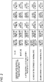
FIG. 2 is a table showing states of a charging circuit, a discharging circuit, and first to third switches shown inFIG. 1 . -
FIG. 3 is a circuit diagram showing an embodiment of a power supply system incorporating a backup power-supply device according to a second embodiment of the present invention. -
FIG. 4 is a table showing states of a charging circuit, a discharging circuit, and first and second switches shown inFIG. 3 . - A specific embodiment according to the present invention will be described below with reference to the accompanying drawings.
- First, a
power supply system 1 incorporating a backup power-supply device 3 according to a first embodiment will be described with reference toFIG. 1 . Thepower supply system 1 according to the present embodiment is mounted on an automobile. As shown inFIG. 1 , thepower supply system 1 according to the first embodiment includes amain battery 2 serving as a main power supply, the backup power-supply device 3 provided for backing up themain battery 2, a firstelectronic device 4, and a secondelectronic device 5 different from the firstelectronic device 4. The firstelectronic device 4 and the secondelectronic device 5 are supplied with power from themain battery 2 and the backup power-supply device 3. - The
main battery 2 supplies power to the firstelectronic device 4 and the secondelectronic device 5. When power is supplied at the time of turning on an ignition, the firstelectronic device 4 is operated, and when power supply is cut off at the time of turning off the ignition, it is not necessary to operate the firstelectronic device 4. The firstelectronic device 4 is an important device for which it is desired to continue the power supply even when an abnormality occurs in themain battery 2 due to an accident or the like and power cannot be supplied from themain battery 2 to the firstelectronic device 4. - The second
electronic device 5 includes a communication device for communicating with a terminal such as a smartphone, a lighting device, an air cleaner, and the like. It is desired to supply power to the secondelectronic device 5 and operate the secondelectronic device 5 for a certain period of time not only when the ignition is turned on, but also after the ignition is turned off. - Next, the backup power-
supply device 3 will be described. The backup power-supply device 3 includes an electricdouble layer capacitor 31 serving as a capacitor, acharging circuit 32, adischarging circuit 33, a conduction path R1, a conduction path R2, adischarge resistor 34, first to third switches S1 to S3, and acontrol unit 35. The electricdouble layer capacitor 31 is provided as a backup for themain battery 2. The electricdouble layer capacitor 31 deteriorates when a state in which electric charges are accumulated continues. Therefore, the electricdouble layer capacitor 31 is sufficiently charged so that a voltage becomes a target voltage in preparation for a case where an abnormality occurs in themain battery 2 when the ignition is turned on, and is discharged until the voltage becomes zero in order to prevent deterioration when the ignition is turned off. - The
charging circuit 32 is provided between a positive pole of themain battery 2 and one end of the electricdouble layer capacitor 31. A negative pole of themain battery 2 and the other end of the electricdouble layer capacitor 31 are connected to the ground. Thecharging circuit 32 can turn on and turn off charging (a power supply) from themain battery 2 to the electricdouble layer capacitor 31. For example, thecharging circuit 32 includes a direct current (DC)/DC converter that steps down or steps up a power supply voltage of themain battery 2 and supplies the stepped-down or stepped-down power supply voltage to the electricdouble layer capacitor 31 when a voltage of themain battery 2 is higher or lower than a voltage of the electricdouble layer capacitor 31, and a switch that turns on or turns off a power supply from themain battery 2 to the DC/DC converter (the DC/DC converter and the switch are not shown). When the voltages of themain battery 2 and the electricdouble layer capacitor 31 are substantially equal to each other, thecharging circuit 32 includes only a switch (not shown). Charging from themain battery 2 to the electricdouble layer capacitor 31 can be turned on or turned off by turning on or turning off the switch provided in thecharging circuit 32. - The
discharging circuit 33 is provided between one end of the electricdouble layer capacitor 31 and the firstelectronic device 4. Thedischarging circuit 33 can turn on and off discharging (a power supply) from the electricdouble layer capacitor 31 to the firstelectronic device 4. For example, thedischarging circuit 33 includes a DC/DC converter that steps down or steps up a voltage of the electricdouble layer capacitor 31 and supplies the stepped-down or stepped-up voltage to the firstelectronic device 4 when a voltage supplied to the firstelectronic device 4 is higher or lower than a voltage of the electricdouble layer capacitor 31, and a switch that turns on or turns off a power supply from the electricdouble layer capacitor 31 to the DC/DC converter (the DC/DC converter and the switch are not shown). When the voltages of the electricdouble layer capacitor 31 and the firstelectronic device 4 are substantially equal to each other, thedischarging circuit 33 includes only a switch. Discharging from the electricdouble layer capacitor 31 to the firstelectronic device 4 can be turned on or turned off by turning on or turning off the switch provided in thedischarging circuit 33. Thecharging circuit 32 and thedischarging circuit 33 described above are controlled by thecontrol unit 35 to be described later. - The conduction path R1 is connected to the first
electronic device 4 and the positive pole of themain battery 2, and bypasses thecharging circuit 32 and thedischarging circuit 33. The conduction path R2 is connected to the secondelectronic device 5 and the positive pole themain battery 2, and bypasses the chargingcircuit 32 and the dischargingcircuit 33. Thedischarge resistor 34 is connected in parallel with the electricdouble layer capacitor 31 between the chargingcircuit 32 and the dischargingcircuit 33. One end of thedischarge resistor 34 is connected to one end of the electricdouble layer capacitor 31 via the third switch S3 to be described later, and the other end of thedischarge resistor 34 is connected to the ground. - The first switch S1 is provided between the second
electronic device 5 and the electricdouble layer capacitor 31. In the present embodiment, the first switch S1 is provided closer to the secondelectronic device 5 than a connection point between the dischargingcircuit 33 and the firstelectronic device 4. When the first switch S1 is turned on, discharging from the electricdouble layer capacitor 31 to the secondelectronic device 5 is enabled, and when the first switch S1 is turned off, discharging from the electricdouble layer capacitor 31 to the secondelectronic device 5 is cut off. - The second switch S2 is provided on the conduction path R2 that connects the second
electronic device 5 and themain battery 2, and is connected in parallel to the first switch S1. When the second switch S2 is turned on, power can be supplied from themain battery 2 to the secondelectronic device 5, and when the second switch S2 is turned off, power supply from themain battery 2 to the secondelectronic device 5 is cut off. - The third switch S3 is provided on a discharge path from the electric
double layer capacitor 31 to thedischarge resistor 34. In the present embodiment, the third switch S3 is connected between one end of the electricdouble layer capacitor 31 and thedischarge resistor 34. More specifically, the electricdouble layer capacitor 31, and thedischarge resistor 34 and the third switch S3 that both are connected in series are connected in parallel between the ground and a connection point of the chargingcircuit 32 and the dischargingcircuit 33. When the third switch S3 is turned on, the electricdouble layer capacitor 31 is discharged by thedischarge resistor 34, and when the third switch S3 is turned off, discharging from the electricdouble layer capacitor 31 to thedischarge resistor 34 is cut off. The first to third switches S1 to S3 are controlled to be turned on and turned off by thecontrol unit 35 to be described later. - The
control unit 35 is connected to the chargingcircuit 32, the dischargingcircuit 33, and the first to third switches S1 to S3 described above, and controls on/off of switches (not shown) included in the chargingcircuit 32 and the dischargingcircuit 33, and the first to third switches S1 to S3. Thecontrol unit 35 includes, for example, a microcomputer (not shown). The microcomputer includes a memory that stores a program and a central processing unit (CPU) that operates in accordance with the program. - Next, an operation of the
power supply system 1 having the above-described configuration will be described with reference toFIG. 2 . In thepower supply system 1 according to the present embodiment, a user can set in advance whether the secondelectronic device 5 is used for a certain period of time after the ignition is turned off or is not used after the ignition is turned off. For example, an input unit of a navigation device or communication with a smartphone can be used to make such a setting. Setting contents can be stored in the memory of thecontrol unit 35. That is, thecontrol unit 35 also functions as a storage unit. - Immediately after the ignition is turned off, the
control unit 35 determines whether the secondelectronic device 5 is set to be used for a certain period of time after the ignition is turned off. When the secondelectronic device 5 is set to be used for a certain period of time after the ignition is turned off, thecontrol unit 35 turns on the switch in the dischargingcircuit 33 and the first switch S1, and turns off the switch in the chargingcircuit 32 and the second and third switches S2 and S3, as shown in (A) ofFIG. 2 . - As a result, charging from the
main battery 2 to the electricdouble layer capacitor 31 and a power supply to the secondelectronic device 5 are cut off, and the electricdouble layer capacitor 31 is discharged by the secondelectronic device 5. When the ignition is turned off, since a switch built in the firstelectronic device 4 is turned off, discharging from the electricdouble layer capacitor 31 to the firstelectronic device 4 is disabled. - On the other hand, when the second
electronic device 5 is set to be not used after the ignition is turned off, thecontrol unit 35 turns on the third switch S3, and turns off the switches in the chargingcircuit 32 and the dischargingcircuit 33 and the first and second switches S1 and S2, as shown in (B) ofFIG. 2 . As a result, charging from themain battery 2 to the electricdouble layer capacitor 31 is cut off. Discharging (a power supply) from themain battery 2 and the electricdouble layer capacitor 31 to the secondelectronic device 5 is cut off, power is not supplied to the secondelectronic device 5 and the secondelectronic device 5 is not used. The electricdouble layer capacitor 31 is discharged by thedischarge resistor 34. - The
control unit 35 detects a voltage of the electricdouble layer capacitor 31, the electricdouble layer capacitor 31 is discharged by the secondelectronic device 5 or thedischarge resistor 34, and when thecontrol unit 35 determines that electric charges becomes zero (that is, the electricdouble layer capacitor 31 is brought into a discharge ending state), thecontrol unit 35 turns off the switches in the chargingcircuit 32 and the dischargingcircuit 33 and the first to third switches S1 to S3, as shown in (C) ofFIG. 2 . That is, when the secondelectronic device 5 is set to be used after the ignition is turned off, power is supplied to the secondelectronic device 5 until electric charges of the electricdouble layer capacitor 31 becomes zero. - When the ignition is tuned on and the
main battery 2 is in a normal state in which no abnormality occurs, thecontrol unit 35 repeatedly turns on and off the switch in the chargingcircuit 32 as shown in (D) ofFIG. 2 . More specifically, thecontrol unit 35 detects a voltage of the electricdouble layer capacitor 31, and when the detected voltage reaches a target voltage, thecontrol unit 35 turns off the chargingcircuit 32 to cut off charging from themain battery 2 to the electricdouble layer capacitor 31. When natural discharging is performed and the detected voltage of the electricdouble layer capacitor 31 falls below the target voltage, thecontrol unit 35 turns on the chargingcircuit 32 to charge the electricdouble layer capacitor 31 from themain battery 2. - As shown in (D) of
FIG. 2 , thecontrol unit 35 turns on the second switch S2 and turns off the switch in the dischargingcircuit 33, the first switch S1, and the third switch S3. As a result, the secondelectronic device 5 is operated by receiving a power supply from themain battery 2, and discharging from the electricdouble layer capacitor 31 to thedischarge resistor 34 or the secondelectronic device 5 is cut off. When the ignition is turned on, since the switch built in the firstelectronic device 4 is turned on, power is supplied from themain battery 2 to the firstelectronic device 4 via the conduction path R1. - When the ignition is turned on and an abnormality occurs in the
main battery 2, thecontrol unit 35 turns on the switch in the dischargingcircuit 33 and turns off the switch in the chargingcircuit 32 and the first to third switches S1 to S3, as shown in (E) ofFIG. 2 . As a result, power can be supplied from the electricdouble layer capacitor 31 to the firstelectronic device 4, and a power supply to the firstelectronic device 4 can be continued even after an abnormality occurs in themain battery 2. In addition, charging from themain battery 2 to the electricdouble layer capacitor 31 and a power supply from themain battery 2 and the electricdouble layer capacitor 31 to the secondelectronic device 5 are cut off. - According to the first embodiment described above, after the ignition is turned off, the
control unit 35 turns on the switch in the dischargingcircuit 33 and the first switch S1 and turns off the switch in the chargingcircuit 32 to perform discharging from the electricdouble layer capacitor 31 to the secondelectronic device 5 and stop charging from themain battery 2 to the electricdouble layer capacitor 31. As a result, after the ignition is turned off, the electricdouble layer capacitor 31 can be discharged so as to prevent deterioration, and discharge energy of the electricdouble layer capacitor 31 can be effectively used as a power supply for the secondelectronic device 5. - According to the first embodiment described above, the
control unit 35 can turn on the second switch S2 to supply power from themain battery 2 to the secondelectronic device 5 in a normal state in which themain battery 2 is normal when the ignition is turned on. In a case where an abnormality occurs in themain battery 2 when the ignition is turned on, after the ignition is turned off, thecontrol unit 35 turns off the second switch S2 to cut off the power supply from themain battery 2 to the secondelectronic device 5, and does not cut off discharging from the electricdouble layer capacitor 31 to the secondelectronic device 5. - According to the first embodiment described above, after the ignition is turned off, the
control unit 35 turns off the second switch S2 to cut off the power supply from themain battery 2 to the secondelectronic device 5 after electric charges of the electricdouble layer capacitor 31 becomes zero. As a result, after the ignition is turned off, the secondelectronic device 5 can be driven for a period of time until when electric charges of the electricdouble layer capacitor 31 becomes zero. - According to the first embodiment described above, in a case where the second
electronic device 5 is set to be used, thecontrol unit 35 turns on the first switch S1 and turns off the third switch S3 after the ignition is turned off, and in a case where the secondelectronic device 5 is set to be not used, thecontrol unit 35 turns off the second switch S2 and turns on the third switch S3 after the ignition is turned off. As a result, even when the secondelectronic device 5 is set to be not used, the electricdouble layer capacitor 31 can be discharged. - Although the electric
double layer capacitor 31 is used as a capacitor in the first embodiment described above, the present invention is not limited thereto. A lithium ion capacitor may be used instead of the electricdouble layer capacitor 31. In this case, thecontrol unit 35 determines that the lithium ion capacitor is brought into a discharge ending state when a voltage of the lithium ion capacitor reaches a specified value. - Although a user can set whether to use or not use the second
electronic device 5 after the ignition is turned off in the first embodiment described above, the present invention is not limited thereto. Alternatively, the secondelectronic device 5 may be constantly used after the ignition is turned off, and it is not necessary to provide thedischarge resistor 34 and the third switch S3. - Next, a
power supply system 1B according to a second embodiment will be described with reference toFIG. 3 . InFIG. 3 , the same components as those of thepower supply system 1 shown inFIG. 1 described above in the first embodiment are denoted by the same reference numerals, and detailed description thereof will be omitted. As shown inFIG. 3 , thepower supply system 1B according to the second embodiment includes themain battery 2, a backup power-supply device 3B provided for backing up themain battery 2, and the firstelectronic device 4 and a secondelectronic device 5B that are supplied with power from themain battery 2 and the backup power-supply device 3B. - The
main battery 2 supplies power to the firstelectronic device 4 and the secondelectronic device 5B. Since the firstelectronic device 4 is the same as that according to the first embodiment, detailed description thereof will be omitted here. The secondelectronic device 5B is a device such as a clock, a smart key, or a memory. It is desired to continue to supply power to the secondelectronic device 5B and operate the secondelectronic device 5B from when the ignition is turned off to when the ignition is turned on. - Next, the backup power-
supply device 3B will be described. The backup power-supply device 3B includes a smalllithium ion capacitor 31B serving as a capacitor, a chargingcircuit 32B, a dischargingcircuit 33B, first and second switches S1B and S2B, a conduction path R3, a conduction path R4, and acontrol unit 35B. The smalllithium ion capacitor 31B deteriorates when a state of full charge continues. Therefore, the smalllithium ion capacitor 31B is sufficiently charged so that a voltage becomes a target voltage in preparation for a case where an abnormality occurs in themain battery 2 when the ignition is turned on, and is discharged until the voltage becomes a specified value lower than the target voltage in order to prevent deterioration when the ignition is turned off. - The charging
circuit 32B is provided between the positive pole of themain battery 2 and one end of the smalllithium ion capacitor 31B. The negative pole of themain battery 2 and the other end of the smalllithium ion capacitor 31B are connected to the ground. The chargingcircuit 32B can turn on and turn off charging (a power supply) from themain battery 2 to the smalllithium ion capacitor 31B. - The discharging
circuit 33B is provided between one end of the smalllithium ion capacitor 31B and the firstelectronic device 4. The dischargingcircuit 33B can turn on and turn off discharging (a power supply) from the smalllithium ion capacitor 31B to the firstelectronic device 4. Since configurations of the chargingcircuit 32B and the dischargingcircuit 33B are the same as configurations of the chargingcircuit 32 and the dischargingcircuit 33 according to the first embodiment, detailed description thereof will be omitted here. - The conduction path R3 is connected to the first
electronic device 4 and the positive pole of themain battery 2, and bypasses the chargingcircuit 32B and the dischargingcircuit 33B. The conduction path R4 is connected between the secondelectronic device 5B and a connection point of the dischargingcircuit 33B and the firstelectronic device 4. The secondelectronic device 5B is connected between the chargingcircuit 32B and themain battery 2. - The first switch S1B is provided between the second
electronic device 5B and the smalllithium ion capacitor 31B. More specifically, the conduction path R4 connects the secondelectronic device 5B and the connection point of the dischargingcircuit 33B and the firstelectronic device 4. The smalllithium ion capacitor 31B is connected to the secondelectronic device 5B by the conduction path R4 via the dischargingcircuit 33B. The first switch S1B is provided on the conduction path R4. When the first switch S1B is turned on, power is supplied from the smalllithium ion capacitor 31B to the secondelectronic device 5B, and when the first switch S1B is turned off, the power supply from the smalllithium ion capacitor 31B to the secondelectronic device 5B is cut off. - The second switch S2B is provided between the second
electronic device 5B and themain battery 2. When the second switch S2B is turned on, power is supplied from themain battery 2 to the firstelectronic device 4 and the secondelectronic device 5B, and when the second switch S2B is turned off, the power supply from themain battery 2 to the firstelectronic device 4 and the secondelectronic device 5B is cut off. - Next, an operation of the
power supply system 1B having the above-described configuration will be described with reference toFIG. 4 . Immediately after the ignition is turned off, thecontrol unit 35B turns on a switch in the dischargingcircuit 33B and the first switch S1B, and turns off a switch in thecharging circuit 32B and the second switch S2B, as shown in (A) ofFIG. 4 . - Accordingly, charging from the
main battery 2 to the smalllithium ion capacitor 31B and a power supply to the firstelectronic device 4 and the secondelectronic device 5B are cut off, and discharging from the smalllithium ion capacitor 31B to the secondelectronic device 5B is performed. When the ignition is turned off, since the switch built in the firstelectronic device 4 is turned off, discharging from the smalllithium ion capacitor 31B to the firstelectronic device 4 is not performed. - Thereafter, when the small
lithium ion capacitor 31B is discharged and a voltage of the smalllithium ion capacitor 31B reaches a specified value (the smalllithium ion capacitor 31B is brought into a discharge ending state), thecontrol unit 35B turns on the second switch S2B, and turns off the switches in thecharging circuit 32B and the dischargingcircuit 33B and the first switch S1B, as shown in (B) ofFIG. 4 . As a result, the power supply from themain battery 2 to the secondelectronic device 5B is continued. - On the other hand, when the ignition is turned on and the
main battery 2 is in a normal state in which no abnormality occurs, thecontrol unit 35B repeatedly turns on and off the switch in thecharging circuit 32B as shown in (C) ofFIG. 4 . Specifically, thecontrol unit 35B detects a voltage of the smalllithium ion capacitor 31B, and when the detected voltage reaches a target voltage, thecontrol unit 35B turns off the chargingcircuit 32B to cut off charging from themain battery 2 to the smalllithium ion capacitor 31B. On the other hand, when natural discharging is performed and the detected voltage falls below the target voltage, thecontrol unit 35B turns on the chargingcircuit 32B to charge the smalllithium ion capacitor 31B from themain battery 2. - As shown in (C) of
FIG. 4 , thecontrol unit 35B turns on the second switch S2B, and turns off the switch in the dischargingcircuit 33B and the first switch S1B. As a result, the secondelectronic device 5B is operated by receiving a power supply from themain battery 2, and discharging from the smalllithium ion capacitor 31B to the secondelectronic device 5B is cut off. When the ignition is turned on, since the switch built in the firstelectronic device 4 is turned on, power is supplied from themain battery 2 to the firstelectronic device 4. - When the ignition is turned on and an abnormality occurs in the
main battery 2, thecontrol unit 35B turns on the switch in the discharging circuit 33b, and turns off the switch in the charging circuit 32b and the first and second switches S1B and S2B, as shown in (D) ofFIG. 4 . As a result, power can be supplied from the smalllithium ion capacitor 31 to the firstelectronic device 4, and a power supply to the firstelectronic device 4 can be continued even after an abnormality occurs in themain battery 2. In addition, charging from themain battery 2 to the smalllithium ion capacitor 31B and a power supply to the secondelectronic device 5B are cut off. - According to the second embodiment described above, after the ignition is turned off, the
control unit 35B turns on the switch in the dischargingcircuit 33B and the first switch S1B and turns off the switch in thecharging circuit 32B to perform discharging from the smalllithium ion capacitor 31B to the secondelectronic device 5B and stop charging from themain battery 2 to the smalllithium ion capacitor 31B. As a result, after the ignition is turned off, the smalllithium ion capacitor 31B can be discharged so as to prevent deterioration, and discharge energy of the smalllithium ion capacitor 31B can be effectively used as a power supply for the secondelectronic device 5B. - According to the second embodiment described above, the
control unit 35B can turn on the second switch S2B to supply power from themain battery 2 to the secondelectronic device 5B in a normal state in which themain battery 2 is normal when the ignition is turned on. In a case where an abnormality occurs in themain battery 2 when the ignition is turned on, after the ignition is turned off, thecontrol unit 35B turns off the second switch S2B to cut off the power supply from themain battery 2 to the secondelectronic device 5B, and does not cut off discharging from the smalllithium ion capacitor 31B to the secondelectronic device 5B. - According to the second embodiment described above, the
control unit 35B turns on the second switch S2B to supply power from themain battery 2 to the secondelectronic device 5B after a voltage of the smalllithium ion capacitor 31B reaches the specified value after the ignition is turned off. As a result, after the ignition is turned off, the secondelectronic device 5B can be driven even after the voltage of the smalllithium ion capacitor 31B reaches the specified value. - Although the small
lithium ion capacitor 31B is used as a capacitor in the second embodiment described above, the present invention is not limited thereto. An electric double layer capacitor may be used instead of the smalllithium ion capacitor 31B. In this case, thecontrol unit 35B determines that the electric double layer capacitor is brought into a discharge ending state when electric charges of the electric double layer capacitor becomes zero. - The present invention is not limited to the embodiments described above, and modifications, improvements, and the like can be made as appropriate. In addition, materials, shapes, dimensions, numbers, arrangement locations and the like of elements in the above embodiments are optional and are not limited as long as the object of the present invention can be achieved.
- Here, features of the embodiments of the backup power-supply device according to the present invention described above will be briefly summarized and listed in the following [1] to [6].
- [1] A backup power-supply device (3, 3B) including:
- a capacitor (31, 31B) provided as a backup for a main power supply (2) that supplies power to a first electronic device (4);
- a charging circuit (32, 32B) that is provided between the main power supply (2) and the capacitor (31, 31B) and configured to turn on and turn off charging from the main power supply (2) to the capacitor (31, 31B);
- a discharging circuit (33, 33B) that is provided between the capacitor (31, 31B) and the first electronic device (4) and configured to turn on and turn off discharging from the capacitor (31, 31B) to the first electronic device (4);
- a control unit (35, 35B) that controls to turn on or turn off the charging circuit (32, 32B) to charge the capacitor (31, 31B) from the main power supply (2) so that a voltage of the capacitor (31, 31B) becomes constant at a target voltage and turns off the discharging circuit (33, 33B) to stop discharging from the capacitor (31, 31B) to the first electronic device (4) in a case where the main power supply (2) is normal when an ignition is turned on, and turns off the charging circuit (32, 32B) to stop charging from the main power supply (2) to the capacitor (31, 31B) and turns on the discharging circuit (33, 33B) to perform discharging from the capacitor (31, 31B) to the first electronic device (4) in a case where an abnormality occurs in the main power supply (2) when the ignition is turned on; and
- a first switch (S1, S1B) provided between the second electronic device (5, 5B) and the capacitor (31, 31B), in which
- the control unit (35, 35B) turns on the discharging circuit (33, 33B) and the first switch (S1, S1B) and turns off the charging circuit (32, 32B) after the ignition is turned off to perform discharging from the capacitor (31, 31B) to the second electronic device (5, 5B) and stop charging from the main power supply (2) to the capacitor (31, 31B).
- According to the configuration of the above [1], after the ignition is turned off, the capacitor (31, 31B) can be discharged so as to prevent deterioration, and the discharge energy of the capacitor (31, 31B) can be effectively used as a power supply for the second electronic device (5, 5B).
- [2] The backup power-supply device (3, 3B) according to [1], further including:
- a second switch (S2, S2B) provided between the second electronic device (5, 5B) and the main power supply (2), in which
- the control unit (35, 35B) turns on the second switch (S2, S2B) to supply power from the main power supply (2) to the second electronic device (5, 5B) in a case where the main power supply (2) is normal when the ignition is turned on, and turns off the second switch (S2, S2B) to cut off the power supply from the main power supply (2) to the second electronic device (5, 5B) after the ignition is turned off in a case where an abnormality occurs in the main power supply (2) when the ignition is turned on.
- According to the configuration of the above [2], the control unit (35, 35B) can turn on the second switch (S2, S2B) to supply power from the main power supply (2) to the second electronic device (5, 5B) in a normal state in which the main power supply (2) is normal when the ignition is turned on. In a case where an abnormality occurs in the main power supply (2) when the ignition is turned on, after the ignition is turned off, the control unit (35, 35B) turns off the second switch (S2, S2B) to cut off the power supply from the main power supply (2) to the second electronic device (5, 5B), and does not cut off discharging from the capacitor (31, 31B) to the second electronic device (5, 5B).
- [3] The backup power-supply device (3) according to [2], in which
the control unit (35) turns off the second switch (S2) and continues to cut off the power supply from the main power supply (2) to the second electronic device (5) after the capacitor (31) is brought into a discharge ending state after the ignition is turned off. - According to the configuration of the above [3], the control unit (35) turns off the second switch (S2) to cut off the power supply from the main power supply (2) to the second electronic device (5) after the capacitor (31) is brought into the discharge ending state after the ignition is turned off. As a result, after the ignition is turned off, the second electronic device (5) can be driven for a period of time until when the
capacitor 31 is brought into the discharge ending state. - [4] The backup power-supply device (3B) according to [2], in which
the control unit (35B) turns on the second switch (S2B) to start to supply power from the main power supply (2) to the second electronic device (5B) after the capacitor (31B) is brought into a discharge ending state after the ignition is turned off. - According to the configuration of the above [4], the control unit (35B) turns on the second switch (S2B) to supply power from the main power supply (2) to the second electronic device (5B) after the capacitor (31B) is brought into the discharge ending state after the ignition is turned off. As a result, after the ignition is turned off, the second electronic device (5B) can be driven even after the capacitor (31B) is brought into the discharge ending state.
- [5] The backup power-supply device (3) according to [3], further including:
- a discharge resistor (34) configured to discharge the capacitor (31);
- a third switch (S3) provided between the capacitor (31) and the discharge resistor (34); and
- a storage unit (35) that stores a setting as to whether to use the second electronic device (5) after the ignition is turned off, in which
- the control unit (35) turns on the first switch (S1) and turns off the third switch (S3) after the ignition is turned off in a case where the second electronic device (5) is set to be used, and turns off the second switch (S2) and turns on the third switch (S3) after the ignition is turned off in a case where the second electronic device (5) is set to be not used.
- According to the configuration of the above [5], in a case where the second electronic device (5) is set to be used, the control unit (35) turns on the first switch (S1) and turns off the third switch (S3) after the ignition is turned off, and in a case where the second electronic device (5) is set to be not used, the control unit (35) turns off the second switch (S2) and turns on the third switch (S3) after the ignition is turned off. As a result, even when the second electronic device (5) is set to be not used, the capacitor (31) can be discharged.
- [6] The backup power-supply device (3, 3B) according to any one of [1] to [5], in which
the capacitor is formed of one of an electric double layer capacitor (31) and a lithium ion capacitor (31B). - According to the configuration of the above [6], the electric double layer capacitor (31) and the lithium ion capacitor (31B) can be effectively used.
Claims (6)
- A backup power-supply device (3, 3B) comprising:a capacitor (31, 31B) that is configured to supply power to a first electronic device (4) and is provided as a backup for a main power supply (2);a charging circuit (32, 32B) that is provided between the main power supply (2) and the capacitor (31, 31B) and is configured to turn on and turn off charging from the main power supply (2) to the capacitor (31, 31B);a discharging circuit (33, 33B) that is provided between the capacitor (31, 31B) and the first electronic device (4) and is configured to turn on and turn off discharging from the capacitor (31, 31B) to the first electronic device (4);a control unit (35, 35B) that is configured to control to turn on or turn off the charging circuit (32, 32B) to charge the capacitor (31, 31B) from the main power supply (2) so that a voltage of the capacitor (31, 31B) becomes constant at a target voltage and turns off the discharging circuit (33, 33B) to stop discharging from the capacitor (31, 31B) to the first electronic device (4) in a case where the main power supply (2) is normal when an ignition is turned on, and turns off the charging circuit (32, 32B) to stop charging from the main power supply (2) to the capacitor (31, 31B) and turns on the discharging circuit (33, 33B) to perform discharging from the capacitor (31, 31B) to the first electronic device (4) in a case where an abnormality occurs in the main power supply (2) when the ignition is turned on; anda first switch (S1, S1B) that is provided between the second electronic device (5, 5B) and the capacitor (31, 31B),wherein the control unit (35, 35B) turns on the discharging circuit (33, 33B) and the first switch (S1, S1B) and turns off the charging circuit (32, 32B) after the ignition is turned off to perform discharging from the capacitor (31, 31B) to the second electronic device (5, 5B) and to stop charging from the main power supply (2) to the capacitor (31, 31B).
- The backup power-supply device (3, 3B) according to claim 1, further comprising:a second switch (S2, S2B) that is provided between the second electronic device (5, 5B) and the main power supply,wherein the control unit turns on the second switch (S2, S2B) to supply power from the main power supply (2) to the second electronic device (5, 5B) in a case where the main power supply (2) is normal when the ignition is turned on, and turns off the second switch (S2, S2B) to cut off the power supply from the main power supply (2) to the second electronic device (5, 5B) after the ignition is turned off in a case where an abnormality occurs in the main power supply(2) when the ignition is turned on.
- The backup power-supply device (3) according to claim 2,
wherein the control unit (35) turns off the second switch (S2) and continues to cut off the power supply from the main power supply (2) to the second electronic device (5) after the capacitor (31) is brought into a discharge ending state after the ignition is turned off. - The backup power-supply device (3B) according to claim 2,
wherein the control unit (35B) turns on the second switch (S2B) to start to supply power from the main power supply (2) to the second electronic device (5B) after the capacitor (31B) is brought into a discharge ending state after the ignition is turned off. - The backup power-supply device (3) according to claim 3, further comprising:a discharge resistor (34) that is configured to discharge the capacitor (31);a third switch (S3) that is provided between the capacitor (31) and the discharge resistor (34); anda storage unit (35) that stores a setting as to whether to use the second electronic device (5) after the ignition is turned off,wherein in a case where the second electronic device (5) is set to be used, the control unit (35) turns on the first switch (S1) and turns off the third switch (S3) after the ignition is turned off, and in a case where the second electronic device (5) is set to be not used, the control unit (35) turns off the second switch (S2) and turns on the third switch (S3) after the ignition is turned off.
- The backup power-supply device (3, 3B) according to any one of claims 1 to 5,
wherein the capacitor is constructed of one of an electric double layer capacitor (31) and a lithium ion capacitor (31B).
Applications Claiming Priority (1)
| Application Number | Priority Date | Filing Date | Title |
|---|---|---|---|
| JP2021121843A JP7658828B2 (en) | 2021-07-26 | 2021-07-26 | Backup Power Supply |
Publications (2)
| Publication Number | Publication Date |
|---|---|
| EP4125179A1 true EP4125179A1 (en) | 2023-02-01 |
| EP4125179B1 EP4125179B1 (en) | 2023-12-20 |
Family
ID=82701812
Family Applications (1)
| Application Number | Title | Priority Date | Filing Date |
|---|---|---|---|
| EP22186520.7A Active EP4125179B1 (en) | 2021-07-26 | 2022-07-22 | Backup power-supply device |
Country Status (4)
| Country | Link |
|---|---|
| US (1) | US11876400B2 (en) |
| EP (1) | EP4125179B1 (en) |
| JP (1) | JP7658828B2 (en) |
| CN (1) | CN115693895B (en) |
Families Citing this family (1)
| Publication number | Priority date | Publication date | Assignee | Title |
|---|---|---|---|---|
| DE102024121747A1 (en) * | 2024-07-31 | 2026-02-05 | Connaught Electronics Ltd. | Electronic protection device for an electronic system, as well as electronic system and method for operating an electronic system |
Citations (2)
| Publication number | Priority date | Publication date | Assignee | Title |
|---|---|---|---|---|
| EP3576250A1 (en) * | 2017-01-27 | 2019-12-04 | Panasonic Intellectual Property Management Co., Ltd. | Vehicle-mounted emergency power supply device |
| JP2020182317A (en) | 2019-04-25 | 2020-11-05 | 矢崎総業株式会社 | Backup power supply |
Family Cites Families (8)
| Publication number | Priority date | Publication date | Assignee | Title |
|---|---|---|---|---|
| JP3625789B2 (en) * | 2001-08-10 | 2005-03-02 | 本田技研工業株式会社 | Vehicle power supply |
| FI118544B (en) * | 2006-07-10 | 2007-12-14 | Waertsilae Finland Oy | Control unit for controlling fuel injection in a large internal combustion engine |
| WO2013125170A1 (en) * | 2012-02-22 | 2013-08-29 | パナソニック株式会社 | Backup power source device and automobile equipped with same |
| JP5964215B2 (en) * | 2012-11-15 | 2016-08-03 | 新電元工業株式会社 | Charge / discharge control circuit, power supply device for vehicle, and failure determination method |
| CN109661330B (en) * | 2016-08-31 | 2022-06-14 | 松下知识产权经营株式会社 | Vehicle power storage device |
| JP6546617B2 (en) * | 2017-05-18 | 2019-07-17 | 矢崎総業株式会社 | Power distribution system |
| JP6685347B2 (en) * | 2018-06-11 | 2020-04-22 | 三菱電機株式会社 | Power control device |
| JP7106228B2 (en) * | 2019-08-27 | 2022-07-26 | 矢崎総業株式会社 | vehicle power system |
-
2021
- 2021-07-26 JP JP2021121843A patent/JP7658828B2/en active Active
-
2022
- 2022-07-22 EP EP22186520.7A patent/EP4125179B1/en active Active
- 2022-07-25 US US17/872,238 patent/US11876400B2/en active Active
- 2022-07-26 CN CN202210882719.7A patent/CN115693895B/en active Active
Patent Citations (2)
| Publication number | Priority date | Publication date | Assignee | Title |
|---|---|---|---|---|
| EP3576250A1 (en) * | 2017-01-27 | 2019-12-04 | Panasonic Intellectual Property Management Co., Ltd. | Vehicle-mounted emergency power supply device |
| JP2020182317A (en) | 2019-04-25 | 2020-11-05 | 矢崎総業株式会社 | Backup power supply |
Also Published As
| Publication number | Publication date |
|---|---|
| US20230027426A1 (en) | 2023-01-26 |
| EP4125179B1 (en) | 2023-12-20 |
| JP2023017517A (en) | 2023-02-07 |
| CN115693895A (en) | 2023-02-03 |
| JP7658828B2 (en) | 2025-04-08 |
| US11876400B2 (en) | 2024-01-16 |
| CN115693895B (en) | 2026-02-03 |
Similar Documents
| Publication | Publication Date | Title |
|---|---|---|
| JP3713770B2 (en) | Secondary battery pack | |
| JP7073865B2 (en) | Redundant power supply system | |
| EP2720309B1 (en) | Electric storage apparatus | |
| EP3002398B1 (en) | Backup power source device and automobile equipped with same | |
| EP3118445B1 (en) | Engine starting device | |
| US9118210B2 (en) | Electrical system and method for a hybrid-electric vehicle | |
| JPH0318665A (en) | Engine starting device | |
| WO2007145240A1 (en) | Secondary battery charging circuit | |
| JP2014150593A (en) | Power supply system for vehicle | |
| JP6201750B2 (en) | Power supply for vehicle | |
| JP5556560B2 (en) | Vehicle power supply | |
| EP4125179B1 (en) | Backup power-supply device | |
| CN110979221A (en) | Power supply control method and device for vehicle and vehicle | |
| JP2002064946A (en) | Power supply | |
| CN110323795A (en) | Vehicle power source device | |
| JP7115302B2 (en) | Backup power supply for autonomous vehicles | |
| JP2002369399A (en) | Battery state adjustment device | |
| GB2364452A (en) | Auxiliary battery control for a starter motor | |
| CN114025996B (en) | Backup power system | |
| JP3118871B2 (en) | In-vehicle battery capacity monitoring system | |
| JPH05150020A (en) | Vehicular battery capacity detecting device | |
| EP4503372A1 (en) | Power supply device and power supply control circuit | |
| JP2011239633A (en) | Battery drive device | |
| US20070096684A1 (en) | Apparatus for controlling electric power for electric vehicle | |
| JP2019199099A (en) | Auxiliary machine battery system |
Legal Events
| Date | Code | Title | Description |
|---|---|---|---|
| PUAI | Public reference made under article 153(3) epc to a published international application that has entered the european phase |
Free format text: ORIGINAL CODE: 0009012 |
|
| STAA | Information on the status of an ep patent application or granted ep patent |
Free format text: STATUS: REQUEST FOR EXAMINATION WAS MADE |
|
| 17P | Request for examination filed |
Effective date: 20220722 |
|
| AK | Designated contracting states |
Kind code of ref document: A1 Designated state(s): AL AT BE BG CH CY CZ DE DK EE ES FI FR GB GR HR HU IE IS IT LI LT LU LV MC MK MT NL NO PL PT RO RS SE SI SK SM TR |
|
| STAA | Information on the status of an ep patent application or granted ep patent |
Free format text: STATUS: EXAMINATION IS IN PROGRESS |
|
| RAP3 | Party data changed (applicant data changed or rights of an application transferred) |
Owner name: YAZAKI CORPORATION |
|
| 17Q | First examination report despatched |
Effective date: 20230510 |
|
| GRAP | Despatch of communication of intention to grant a patent |
Free format text: ORIGINAL CODE: EPIDOSNIGR1 |
|
| STAA | Information on the status of an ep patent application or granted ep patent |
Free format text: STATUS: GRANT OF PATENT IS INTENDED |
|
| GRAS | Grant fee paid |
Free format text: ORIGINAL CODE: EPIDOSNIGR3 |
|
| INTG | Intention to grant announced |
Effective date: 20231019 |
|
| GRAA | (expected) grant |
Free format text: ORIGINAL CODE: 0009210 |
|
| STAA | Information on the status of an ep patent application or granted ep patent |
Free format text: STATUS: THE PATENT HAS BEEN GRANTED |
|
| AK | Designated contracting states |
Kind code of ref document: B1 Designated state(s): AL AT BE BG CH CY CZ DE DK EE ES FI FR GB GR HR HU IE IS IT LI LT LU LV MC MK MT NL NO PL PT RO RS SE SI SK SM TR |
|
| REG | Reference to a national code |
Ref country code: GB Ref legal event code: FG4D |
|
| REG | Reference to a national code |
Ref country code: CH Ref legal event code: EP |
|
| REG | Reference to a national code |
Ref country code: DE Ref legal event code: R096 Ref document number: 602022001385 Country of ref document: DE |
|
| REG | Reference to a national code |
Ref country code: IE Ref legal event code: FG4D |
|
| PG25 | Lapsed in a contracting state [announced via postgrant information from national office to epo] |
Ref country code: GR Free format text: LAPSE BECAUSE OF FAILURE TO SUBMIT A TRANSLATION OF THE DESCRIPTION OR TO PAY THE FEE WITHIN THE PRESCRIBED TIME-LIMIT Effective date: 20240321 |
|
| REG | Reference to a national code |
Ref country code: LT Ref legal event code: MG9D |
|
| PG25 | Lapsed in a contracting state [announced via postgrant information from national office to epo] |
Ref country code: LT Free format text: LAPSE BECAUSE OF FAILURE TO SUBMIT A TRANSLATION OF THE DESCRIPTION OR TO PAY THE FEE WITHIN THE PRESCRIBED TIME-LIMIT Effective date: 20231220 |
|
| REG | Reference to a national code |
Ref country code: NL Ref legal event code: MP Effective date: 20231220 |
|
| PG25 | Lapsed in a contracting state [announced via postgrant information from national office to epo] |
Ref country code: ES Free format text: LAPSE BECAUSE OF FAILURE TO SUBMIT A TRANSLATION OF THE DESCRIPTION OR TO PAY THE FEE WITHIN THE PRESCRIBED TIME-LIMIT Effective date: 20231220 |
|
| PG25 | Lapsed in a contracting state [announced via postgrant information from national office to epo] |
Ref country code: LT Free format text: LAPSE BECAUSE OF FAILURE TO SUBMIT A TRANSLATION OF THE DESCRIPTION OR TO PAY THE FEE WITHIN THE PRESCRIBED TIME-LIMIT Effective date: 20231220 Ref country code: GR Free format text: LAPSE BECAUSE OF FAILURE TO SUBMIT A TRANSLATION OF THE DESCRIPTION OR TO PAY THE FEE WITHIN THE PRESCRIBED TIME-LIMIT Effective date: 20240321 Ref country code: FI Free format text: LAPSE BECAUSE OF FAILURE TO SUBMIT A TRANSLATION OF THE DESCRIPTION OR TO PAY THE FEE WITHIN THE PRESCRIBED TIME-LIMIT Effective date: 20231220 Ref country code: ES Free format text: LAPSE BECAUSE OF FAILURE TO SUBMIT A TRANSLATION OF THE DESCRIPTION OR TO PAY THE FEE WITHIN THE PRESCRIBED TIME-LIMIT Effective date: 20231220 Ref country code: BG Free format text: LAPSE BECAUSE OF FAILURE TO SUBMIT A TRANSLATION OF THE DESCRIPTION OR TO PAY THE FEE WITHIN THE PRESCRIBED TIME-LIMIT Effective date: 20240320 |
|
| REG | Reference to a national code |
Ref country code: AT Ref legal event code: MK05 Ref document number: 1643298 Country of ref document: AT Kind code of ref document: T Effective date: 20231220 |
|
| PG25 | Lapsed in a contracting state [announced via postgrant information from national office to epo] |
Ref country code: NL Free format text: LAPSE BECAUSE OF FAILURE TO SUBMIT A TRANSLATION OF THE DESCRIPTION OR TO PAY THE FEE WITHIN THE PRESCRIBED TIME-LIMIT Effective date: 20231220 |
|
| PG25 | Lapsed in a contracting state [announced via postgrant information from national office to epo] |
Ref country code: SE Free format text: LAPSE BECAUSE OF FAILURE TO SUBMIT A TRANSLATION OF THE DESCRIPTION OR TO PAY THE FEE WITHIN THE PRESCRIBED TIME-LIMIT Effective date: 20231220 Ref country code: RS Free format text: LAPSE BECAUSE OF FAILURE TO SUBMIT A TRANSLATION OF THE DESCRIPTION OR TO PAY THE FEE WITHIN THE PRESCRIBED TIME-LIMIT Effective date: 20231220 Ref country code: NO Free format text: LAPSE BECAUSE OF FAILURE TO SUBMIT A TRANSLATION OF THE DESCRIPTION OR TO PAY THE FEE WITHIN THE PRESCRIBED TIME-LIMIT Effective date: 20240320 Ref country code: NL Free format text: LAPSE BECAUSE OF FAILURE TO SUBMIT A TRANSLATION OF THE DESCRIPTION OR TO PAY THE FEE WITHIN THE PRESCRIBED TIME-LIMIT Effective date: 20231220 Ref country code: LV Free format text: LAPSE BECAUSE OF FAILURE TO SUBMIT A TRANSLATION OF THE DESCRIPTION OR TO PAY THE FEE WITHIN THE PRESCRIBED TIME-LIMIT Effective date: 20231220 Ref country code: HR Free format text: LAPSE BECAUSE OF FAILURE TO SUBMIT A TRANSLATION OF THE DESCRIPTION OR TO PAY THE FEE WITHIN THE PRESCRIBED TIME-LIMIT Effective date: 20231220 |
|
| PG25 | Lapsed in a contracting state [announced via postgrant information from national office to epo] |
Ref country code: IS Free format text: LAPSE BECAUSE OF FAILURE TO SUBMIT A TRANSLATION OF THE DESCRIPTION OR TO PAY THE FEE WITHIN THE PRESCRIBED TIME-LIMIT Effective date: 20240420 |
|
| PG25 | Lapsed in a contracting state [announced via postgrant information from national office to epo] |
Ref country code: CZ Free format text: LAPSE BECAUSE OF FAILURE TO SUBMIT A TRANSLATION OF THE DESCRIPTION OR TO PAY THE FEE WITHIN THE PRESCRIBED TIME-LIMIT Effective date: 20231220 Ref country code: AT Free format text: LAPSE BECAUSE OF FAILURE TO SUBMIT A TRANSLATION OF THE DESCRIPTION OR TO PAY THE FEE WITHIN THE PRESCRIBED TIME-LIMIT Effective date: 20231220 |
|
| PG25 | Lapsed in a contracting state [announced via postgrant information from national office to epo] |
Ref country code: SK Free format text: LAPSE BECAUSE OF FAILURE TO SUBMIT A TRANSLATION OF THE DESCRIPTION OR TO PAY THE FEE WITHIN THE PRESCRIBED TIME-LIMIT Effective date: 20231220 |
|
| PG25 | Lapsed in a contracting state [announced via postgrant information from national office to epo] |
Ref country code: SM Free format text: LAPSE BECAUSE OF FAILURE TO SUBMIT A TRANSLATION OF THE DESCRIPTION OR TO PAY THE FEE WITHIN THE PRESCRIBED TIME-LIMIT Effective date: 20231220 Ref country code: SK Free format text: LAPSE BECAUSE OF FAILURE TO SUBMIT A TRANSLATION OF THE DESCRIPTION OR TO PAY THE FEE WITHIN THE PRESCRIBED TIME-LIMIT Effective date: 20231220 Ref country code: RO Free format text: LAPSE BECAUSE OF FAILURE TO SUBMIT A TRANSLATION OF THE DESCRIPTION OR TO PAY THE FEE WITHIN THE PRESCRIBED TIME-LIMIT Effective date: 20231220 Ref country code: IT Free format text: LAPSE BECAUSE OF FAILURE TO SUBMIT A TRANSLATION OF THE DESCRIPTION OR TO PAY THE FEE WITHIN THE PRESCRIBED TIME-LIMIT Effective date: 20231220 Ref country code: IS Free format text: LAPSE BECAUSE OF FAILURE TO SUBMIT A TRANSLATION OF THE DESCRIPTION OR TO PAY THE FEE WITHIN THE PRESCRIBED TIME-LIMIT Effective date: 20240420 Ref country code: EE Free format text: LAPSE BECAUSE OF FAILURE TO SUBMIT A TRANSLATION OF THE DESCRIPTION OR TO PAY THE FEE WITHIN THE PRESCRIBED TIME-LIMIT Effective date: 20231220 Ref country code: CZ Free format text: LAPSE BECAUSE OF FAILURE TO SUBMIT A TRANSLATION OF THE DESCRIPTION OR TO PAY THE FEE WITHIN THE PRESCRIBED TIME-LIMIT Effective date: 20231220 Ref country code: AT Free format text: LAPSE BECAUSE OF FAILURE TO SUBMIT A TRANSLATION OF THE DESCRIPTION OR TO PAY THE FEE WITHIN THE PRESCRIBED TIME-LIMIT Effective date: 20231220 |
|
| PG25 | Lapsed in a contracting state [announced via postgrant information from national office to epo] |
Ref country code: PT Free format text: LAPSE BECAUSE OF FAILURE TO SUBMIT A TRANSLATION OF THE DESCRIPTION OR TO PAY THE FEE WITHIN THE PRESCRIBED TIME-LIMIT Effective date: 20240422 Ref country code: PL Free format text: LAPSE BECAUSE OF FAILURE TO SUBMIT A TRANSLATION OF THE DESCRIPTION OR TO PAY THE FEE WITHIN THE PRESCRIBED TIME-LIMIT Effective date: 20231220 |
|
| PG25 | Lapsed in a contracting state [announced via postgrant information from national office to epo] |
Ref country code: PT Free format text: LAPSE BECAUSE OF FAILURE TO SUBMIT A TRANSLATION OF THE DESCRIPTION OR TO PAY THE FEE WITHIN THE PRESCRIBED TIME-LIMIT Effective date: 20240422 Ref country code: PL Free format text: LAPSE BECAUSE OF FAILURE TO SUBMIT A TRANSLATION OF THE DESCRIPTION OR TO PAY THE FEE WITHIN THE PRESCRIBED TIME-LIMIT Effective date: 20231220 |
|
| REG | Reference to a national code |
Ref country code: DE Ref legal event code: R097 Ref document number: 602022001385 Country of ref document: DE |
|
| PG25 | Lapsed in a contracting state [announced via postgrant information from national office to epo] |
Ref country code: DK Free format text: LAPSE BECAUSE OF FAILURE TO SUBMIT A TRANSLATION OF THE DESCRIPTION OR TO PAY THE FEE WITHIN THE PRESCRIBED TIME-LIMIT Effective date: 20231220 |
|
| PLBE | No opposition filed within time limit |
Free format text: ORIGINAL CODE: 0009261 |
|
| STAA | Information on the status of an ep patent application or granted ep patent |
Free format text: STATUS: NO OPPOSITION FILED WITHIN TIME LIMIT |
|
| PG25 | Lapsed in a contracting state [announced via postgrant information from national office to epo] |
Ref country code: SI Free format text: LAPSE BECAUSE OF FAILURE TO SUBMIT A TRANSLATION OF THE DESCRIPTION OR TO PAY THE FEE WITHIN THE PRESCRIBED TIME-LIMIT Effective date: 20231220 |
|
| PG25 | Lapsed in a contracting state [announced via postgrant information from national office to epo] |
Ref country code: SI Free format text: LAPSE BECAUSE OF FAILURE TO SUBMIT A TRANSLATION OF THE DESCRIPTION OR TO PAY THE FEE WITHIN THE PRESCRIBED TIME-LIMIT Effective date: 20231220 Ref country code: DK Free format text: LAPSE BECAUSE OF FAILURE TO SUBMIT A TRANSLATION OF THE DESCRIPTION OR TO PAY THE FEE WITHIN THE PRESCRIBED TIME-LIMIT Effective date: 20231220 |
|
| 26N | No opposition filed |
Effective date: 20240923 |
|
| PG25 | Lapsed in a contracting state [announced via postgrant information from national office to epo] |
Ref country code: MC Free format text: LAPSE BECAUSE OF FAILURE TO SUBMIT A TRANSLATION OF THE DESCRIPTION OR TO PAY THE FEE WITHIN THE PRESCRIBED TIME-LIMIT Effective date: 20231220 |
|
| PG25 | Lapsed in a contracting state [announced via postgrant information from national office to epo] |
Ref country code: LU Free format text: LAPSE BECAUSE OF NON-PAYMENT OF DUE FEES Effective date: 20240722 |
|
| PG25 | Lapsed in a contracting state [announced via postgrant information from national office to epo] |
Ref country code: LU Free format text: LAPSE BECAUSE OF NON-PAYMENT OF DUE FEES Effective date: 20240722 |
|
| PG25 | Lapsed in a contracting state [announced via postgrant information from national office to epo] |
Ref country code: BE Free format text: LAPSE BECAUSE OF NON-PAYMENT OF DUE FEES Effective date: 20240731 |
|
| PG25 | Lapsed in a contracting state [announced via postgrant information from national office to epo] |
Ref country code: FR Free format text: LAPSE BECAUSE OF NON-PAYMENT OF DUE FEES Effective date: 20240731 |
|
| REG | Reference to a national code |
Ref country code: BE Ref legal event code: MM Effective date: 20240731 |
|
| PG25 | Lapsed in a contracting state [announced via postgrant information from national office to epo] |
Ref country code: IE Free format text: LAPSE BECAUSE OF NON-PAYMENT OF DUE FEES Effective date: 20240722 |
|
| PGFP | Annual fee paid to national office [announced via postgrant information from national office to epo] |
Ref country code: DE Payment date: 20250528 Year of fee payment: 4 |
|
| PG25 | Lapsed in a contracting state [announced via postgrant information from national office to epo] |
Ref country code: CY Free format text: LAPSE BECAUSE OF FAILURE TO SUBMIT A TRANSLATION OF THE DESCRIPTION OR TO PAY THE FEE WITHIN THE PRESCRIBED TIME-LIMIT; INVALID AB INITIO Effective date: 20220722 |
|
| REG | Reference to a national code |
Ref country code: CH Ref legal event code: H13 Free format text: ST27 STATUS EVENT CODE: U-0-0-H10-H13 (AS PROVIDED BY THE NATIONAL OFFICE) Effective date: 20260224 |
|
| PG25 | Lapsed in a contracting state [announced via postgrant information from national office to epo] |
Ref country code: HU Free format text: LAPSE BECAUSE OF FAILURE TO SUBMIT A TRANSLATION OF THE DESCRIPTION OR TO PAY THE FEE WITHIN THE PRESCRIBED TIME-LIMIT; INVALID AB INITIO Effective date: 20220722 |
|
| PG25 | Lapsed in a contracting state [announced via postgrant information from national office to epo] |
Ref country code: CH Free format text: LAPSE BECAUSE OF NON-PAYMENT OF DUE FEES Effective date: 20250731 |