EP4125163A1 - Self-ejecting electrical connection system - Google Patents
Self-ejecting electrical connection system Download PDFInfo
- Publication number
- EP4125163A1 EP4125163A1 EP22187549.5A EP22187549A EP4125163A1 EP 4125163 A1 EP4125163 A1 EP 4125163A1 EP 22187549 A EP22187549 A EP 22187549A EP 4125163 A1 EP4125163 A1 EP 4125163A1
- Authority
- EP
- European Patent Office
- Prior art keywords
- plunger
- connector body
- locking
- engaged position
- disengaged position
- Prior art date
- Legal status (The legal status is an assumption and is not a legal conclusion. Google has not performed a legal analysis and makes no representation as to the accuracy of the status listed.)
- Granted
Links
Images






Classifications
-
- H—ELECTRICITY
- H01—ELECTRIC ELEMENTS
- H01R—ELECTRICALLY-CONDUCTIVE CONNECTIONS; STRUCTURAL ASSOCIATIONS OF A PLURALITY OF MUTUALLY-INSULATED ELECTRICAL CONNECTING ELEMENTS; COUPLING DEVICES; CURRENT COLLECTORS
- H01R13/00—Details of coupling devices of the kinds covered by groups H01R12/70 or H01R24/00 - H01R33/00
- H01R13/62—Means for facilitating engagement or disengagement of coupling parts or for holding them in engagement
- H01R13/629—Additional means for facilitating engagement or disengagement of coupling parts, e.g. aligning or guiding means, levers, gas pressure electrical locking indicators, manufacturing tolerances
- H01R13/633—Additional means for facilitating engagement or disengagement of coupling parts, e.g. aligning or guiding means, levers, gas pressure electrical locking indicators, manufacturing tolerances for disengagement only
- H01R13/635—Additional means for facilitating engagement or disengagement of coupling parts, e.g. aligning or guiding means, levers, gas pressure electrical locking indicators, manufacturing tolerances for disengagement only by mechanical pressure, e.g. spring force
-
- H—ELECTRICITY
- H01—ELECTRIC ELEMENTS
- H01R—ELECTRICALLY-CONDUCTIVE CONNECTIONS; STRUCTURAL ASSOCIATIONS OF A PLURALITY OF MUTUALLY-INSULATED ELECTRICAL CONNECTING ELEMENTS; COUPLING DEVICES; CURRENT COLLECTORS
- H01R13/00—Details of coupling devices of the kinds covered by groups H01R12/70 or H01R24/00 - H01R33/00
- H01R13/62—Means for facilitating engagement or disengagement of coupling parts or for holding them in engagement
- H01R13/627—Snap or like fastening
- H01R13/6271—Latching means integral with the housing
- H01R13/6272—Latching means integral with the housing comprising a single latching arm
-
- H—ELECTRICITY
- H01—ELECTRIC ELEMENTS
- H01R—ELECTRICALLY-CONDUCTIVE CONNECTIONS; STRUCTURAL ASSOCIATIONS OF A PLURALITY OF MUTUALLY-INSULATED ELECTRICAL CONNECTING ELEMENTS; COUPLING DEVICES; CURRENT COLLECTORS
- H01R13/00—Details of coupling devices of the kinds covered by groups H01R12/70 or H01R24/00 - H01R33/00
- H01R13/64—Means for preventing incorrect coupling
- H01R13/641—Means for preventing incorrect coupling by indicating incorrect coupling; by indicating correct or full engagement
Definitions
- This disclosure is directed to an electrical connector with self-ejecting features.
- an electrical connector system includes a first connector body defining a locking fin, a second connector body configured to receive the first connector body, and a flexible locking arm defined by the second connector body configured to releasably engage the locking fin.
- a plunger is slidably attached to the second connector body and is moveable from an engaged position in which the plunger holds the locking arm in engagement with the locking fin to a disengaged position in which the plunger disengages the locking arm from the locking fin.
- the electrical connector system also includes a spring disposed between the plunger and the second connector body. This spring is configured to urge the plunger into the engaged position.
- a push surface on a flexible arm of the plunger contacts a forward end of the first connector body as the first connector body is inserted within the second connector body, thereby compressing the spring and moving the plunger from the engaged position to the disengaged position.
- the second connector body is configured to bend the flexible arm such that the push surface no longer contacts the forward end of the first connector body as the plunger reaches the disengaged position, thereby allowing the plunger to return from the disengaged position to the engaged position.
- compression of the spring causes the push surface on the flexible arm of the plunger to exert a force on the forward end of the first connector body when the push surface is in contact with the forward end, thereby urging the first and second connector bodies apart.
- the second connector body defines a guide channel in which a portion of the flexible arm is disposed.
- the guide channel defines a ramp surface configured to bend the flexible arm such that the push surface no longer contacts the forward end of the first connector body as the plunger reaches the disengaged position.
- the plunger defines a first tab having a first angled surface and the locking arm defines a second tab having a second angled surface.
- the first angled surface contacts the second angled surface as the plunger moves from the engaged position to the disengaged position, thereby lifting an end of the locking arm over the locking fin.
- the first tab holds the end of the locking arm over the locking fin when the plunger is in the disengaged position.
- the plunger is configured to lift the locking arm over the locking fin when the plunger is in the disengaged position.
- the locking arm defines an aperture in which the locking fin is received when the plunger is in the engaged position.
- the plunger and the second connector body are formed of a polymeric material.
- the electrical connector system further includes a metallic clip that is disposed within the second connector body. The spring is disposed between the plunger and the metallic clip.
- the spring is compressed when the plunger is moved from the engaged position to the disengaged position.
- the spring is relaxed when the plunger is in the engaged position.
- a portion of the plunger blocks upward movement of the locking arm when the plunger is in the engaged position, thereby providing connector position assurance.
- the method further includes blocking upward movement of the locking arm by positioning a portion of the plunger over the locking arm when the plunger is in the engaged position, thereby providing connector position assurance.
- the spring is compressed when the plunger is moved from the engaged position.
- the spring is relaxed when the plunger is in the engaged position.
- the spring is compressed as the plunger is moved from the engaged position.
- the spring is relaxed when the plunger is in the engaged position.
- This disclosure is directed to an electrical connector system in which two mating connectors are configured to self-eject or automatically separate unless completely and properly mated together.
- This self-ejecting feature helps to assure a proper connection is made and maintained between the mating connectors because an assembly operator is more likely to detect the separated connectors than partially mated connectors.
- One of the connectors includes a spring or a similar force generating device that is configured to urge the connectors apart until locking features in each of the mating connectors are properly engaged.
- the connector system further includes movable plunger locks and unlocks the locking features as it moved between an engaged position and a disengaged position.
- the plunger also includes a connector position assurance (CPA) feature that is configured to inhibit inadvertent unlocking and disconnection of the locking features when the plunger is in the engaged position.
- CPA connector position assurance
- the plunger brings the spring to a relaxed condition when it is in the engaged position.
- the lock features can be manually disengaged using the plunger to disconnect the two mating connectors. When this occurs, the spring will urge the two mating connectors apart to break the electrical connection.
- the electrical connector system includes a first connector 102, in this example a male connector, having a first connector body 104 formed of an electrically insulative material.
- the first connector body 104 defines a locking fin 106 near a forward edge of the first connector body 104.
- forward and rearward directions are referenced in relation to a longitudinal axis of the first connector 102 in the direction in which the first connector 102 is inserted within a second mating connector 108 of the electrical connector system 100.
- the locking fin 106 has an acutely angled surface relative to the first connector body 104 on its forward face and a perpendicular surface on its rearward face.
- the second connector 108 in this example a female connector and shown in more detail in Fig. 2 , has a second connector body 110 that defines a shroud 112 configured to receive the first connector body 104.
- the first connector 102 includes a plurality of electrical terminals 114 disposed within the first connector body 104 that are designed to mate with a plurality of corresponding mating electrical terminals 116 disposed within the second connector body 110 of the second connector 108 as best shown in Fig. 9 .
- the second connector body 110 includes a flexible locking arm 118 that is configured to releasably engage the locking fin 106 in order to maintain a connection between the first and second connector bodies 104, 110 and thereby maintain a connection between the electrical terminals 114 in the first connector body 104 and the mating electrical terminals 116 in the second connector body 110 of the second connector 108.
- the second connector 108 also includes a plunger 120 that is slidably attached to the second connector body 110.
- the plunger 120 is moveable from an engaged position 122 in which the plunger 120 holds the locking arm 118 in engagement with the locking fin 106 to a disengaged position 124 in which the plunger 120 disengages the locking arm 118 from the locking fin 106.
- the second connector 108 further includes a pair of compression coil springs 126 disposed between the plunger 120 and the second connector body 110. These springs 126 are configured to urge the plunger 120 into the engaged position 122. In alternative embodiments, these springs may be replaced by other types of springs that urge the plunger 120 into the engaged position 122, for example leaf compression springs, polymeric compression springs, pneumatic compression springs, or extension springs.
- a push surface 128 on a fore end of a flexible arm 130 of the plunger 120 contacts a forward end 132 of the first connector body 104 as the first connector body 104 is inserted within the second connector body 110, thereby compressing the springs 126 and moving the plunger 120 from the engaged position 122 to the disengaged position 124 as shown in Figs. 3A and 4A .
- the compression of the springs 126 exert a force between the first and second connector bodies 104, 110 that push the first and second connectors 102, 108 apart. This force is overcome by the application of a counteracting force applied to the first and second connectors 102, 108 by an assembly operator as the first and second connectors 102, 108 are mated.
- fore and aft directions are referenced in relation to a longitudinal axis of the second connector 108 in the direction in which the second connector 108 is mated with the first connector 102.
- a portion 134 of the flexible arm 130 is disposed within a guide channel 136 in the second connector body 110 and a rearward end of this guide channel 136 defines an angled ramp feature 138.
- the ramp feature 138 bends the flexible arm 130 upward so that the push surface 128 no longer contacts the forward end 132 of the first connector body 104 as shown in Fig. 6A . This allows the plunger 120 to return from the disengaged position 124 toward the engaged position 122.
- the plunger 120 defines a first tab 140 having a first angled surface 142 on its aft end and the locking arm 118 defines a second tab 144 having a second angled surface 146 on its fore end.
- the first angled surface 142 contacts the second angled surface 146 as the plunger 120 moves from the engaged position 122 to the disengaged position 124 and lifts the forward end of the locking arm 118 over the locking fin 106 of the first connector body 104.
- the first tab 140 lifts and holds the fore end of the locking arm 118 over the locking fin 106 when the plunger 120 is in the disengaged position 124, thereby disengaging the locking arm 118 from the locking fin 106 and allowing the first connector body 104 to be separated and removed from the second connector body 110.
- the locking arm 118 defines an aperture 148 in which the locking fin 106 is received after the plunger 120 is moved from the disengaged position 124 the engaged position 122 and the first tab 140 is no longer engaged with the second tab 144 as shown in Fig. 7 .
- the springs 126 are compressed when the plunger 120 is moved from the engaged position 122 to the disengaged position 124 and are relaxed when the plunger 120 is in the engaged position 122 as shown in Figs 3B , 4B , 5B , and 6B .
- the plunger 120 and the second connector body 110 are formed of a polymeric material.
- the electrical connector system 100 further comprises a metallic clip 150 that is disposed within the second connector body 110.
- the springs 126 are disposed between the plunger 120 and the metallic clip 150.
- the metallic clip provides the benefit of reducing the amount of polymer creep in the second connector body 110 that may occur over time.
- a portion 152 of the plunger 120 is configured to block upward movement of the locking arm 118 when the plunger 120 is in the engaged position 122, thereby providing a connector position assurance function.
- the forward end 154 of the plunger 120 may contact the second connector body 110 to prevent the plunger 120 from moving beyond the engaged position 122 as illustrated in Fig. 8 .
- a method of connecting the electrical connector system described above includes the steps of :
- the method also may include the step of blocking upward movement of the locking arm 118 by positioning a portion 152 of the plunger 120 over the locking arm 118 when the plunger 120 is in the engaged position 122, thereby providing connector position assurance as shown in Fig. 7 .
- the springs 126 are compressed as the plunger 120 is moved from the engaged position 122 and are relaxed when the plunger 120 is in the engaged position 122 as shown in Figs. 3B , 4B , 5B , and 6B .
- a method of disconnecting the electrical connector system described above includes the steps of:
- the springs 126 are compressed as the plunger 120 is moved from the engaged position 122 and relaxed when the plunger 120 is in the engaged position 122 as shown in Figs. 12B , 13B , and 14B .
- 'one or more' includes a function being performed by one element, a function being performed by more than one element, e.g., in a distributed fashion, several functions being performed by one element, several functions being performed by several elements, or any combination of the above.
- first, second, etc. are, in some instances, used herein to describe various elements, these elements should not be limited by these terms. These terms are only used to distinguish one element from another.
- a first contact could be termed a second contact, and, similarly, a second contact could be termed a first contact, without departing from the scope of the various described embodiments.
- the first contact and the second contact are both contacts, but they are not the same contact.
- the term “if' is, optionally, construed to mean “when” or “upon” or “in response to determining” or “in response to detecting,” depending on the context.
- the phrase “if it is determined” or “if [a stated condition or event] is detected” is, optionally, construed to mean “upon determining” or “in response to determining” or “upon detecting [the stated condition or event]” or “in response to detecting [the stated condition or event],” depending on the context.
Landscapes
- Details Of Connecting Devices For Male And Female Coupling (AREA)
Abstract
Description
- This disclosure is directed to an electrical connector with self-ejecting features.
- Existing electrical connection systems with self-ejecting features do not totally guide the thrust member on the locking device. Locking devices made from plastic can fail over time due to polymer creep. Existing electrical connection systems typically require additional features in the male connector housing to provide self-ejection functions.
- According to one or more aspects of the present disclosure, an electrical connector system includes a first connector body defining a locking fin, a second connector body configured to receive the first connector body, and a flexible locking arm defined by the second connector body configured to releasably engage the locking fin. A plunger is slidably attached to the second connector body and is moveable from an engaged position in which the plunger holds the locking arm in engagement with the locking fin to a disengaged position in which the plunger disengages the locking arm from the locking fin. The electrical connector system also includes a spring disposed between the plunger and the second connector body. This spring is configured to urge the plunger into the engaged position.
- In one or more embodiments of the electrical connector system according to the previous paragraph, a push surface on a flexible arm of the plunger contacts a forward end of the first connector body as the first connector body is inserted within the second connector body, thereby compressing the spring and moving the plunger from the engaged position to the disengaged position.
- In one or more embodiments of the electrical connector system according to any one of the previous paragraphs, the second connector body is configured to bend the flexible arm such that the push surface no longer contacts the forward end of the first connector body as the plunger reaches the disengaged position, thereby allowing the plunger to return from the disengaged position to the engaged position.
- In one or more embodiments of the electrical connector system according to any one of the previous paragraphs, compression of the spring causes the push surface on the flexible arm of the plunger to exert a force on the forward end of the first connector body when the push surface is in contact with the forward end, thereby urging the first and second connector bodies apart.
- In one or more embodiments of the electrical connector system according to any one of the previous paragraphs, the second connector body defines a guide channel in which a portion of the flexible arm is disposed. The guide channel defines a ramp surface configured to bend the flexible arm such that the push surface no longer contacts the forward end of the first connector body as the plunger reaches the disengaged position.
- In one or more embodiments of the electrical connector system according to any one of the previous paragraphs, the plunger defines a first tab having a first angled surface and the locking arm defines a second tab having a second angled surface. The first angled surface contacts the second angled surface as the plunger moves from the engaged position to the disengaged position, thereby lifting an end of the locking arm over the locking fin.
- In one or more embodiments of the electrical connector system according to any one of the previous paragraphs, the first tab holds the end of the locking arm over the locking fin when the plunger is in the disengaged position.
- In one or more embodiments of the electrical connector system according to any one of the previous paragraphs, the plunger is configured to lift the locking arm over the locking fin when the plunger is in the disengaged position.
- In one or more embodiments of the electrical connector system according to any one of the previous paragraphs, the locking arm defines an aperture in which the locking fin is received when the plunger is in the engaged position.
- In one or more embodiments of the electrical connector system according to any one of the previous paragraphs, the plunger and the second connector body are formed of a polymeric material. The electrical connector system further includes a metallic clip that is disposed within the second connector body. The spring is disposed between the plunger and the metallic clip.
- In one or more embodiments of the electrical connector system according to any one of the previous paragraphs, the spring is compressed when the plunger is moved from the engaged position to the disengaged position.
- In one or more embodiments of the electrical connector system according to any one of the previous paragraphs, the spring is relaxed when the plunger is in the engaged position.
- In one or more embodiments of the electrical connector system according to any one of the previous paragraphs, a portion of the plunger blocks upward movement of the locking arm when the plunger is in the engaged position, thereby providing connector position assurance.
- According to one or more aspects of the present disclosure, a method of connecting an electrical connector system which includes a first connector body defining a locking fin, a second connector body configured to receive the first connector body, a flexible locking arm defined by the second connector body configured to releasably engage the locking fin, a plunger slidably attached to the second connector body and moveable from an engaged position in which the plunger holds the locking arm in engagement with the locking fin to a disengaged position in which the plunger disengages the locking arm from the locking fin, and a spring disposed between the plunger and the second connector body and configured to urge the plunger into the engaged position includes the steps of:
- inserting the second connector body within the first connector body;
- moving the plunger from the engaged position to the disengaged position via contact between a push surface on a flexible arm of the plunger and a forward end of the first connector body as the first connector body is inserted within the second connector body;
- compressing the spring as the plunger moves from the engaged position to the disengaged position, thereby exerting a force on the forward end of the first connector body and urging the first and second connector bodies apart;
- lifting the flexible locking arm over the locking fin as the plunger moves from the engaged position to the disengaged position;
- bending the flexible arm such that the push surface no longer contacts the forward end of the first connector body as the plunger reaches the disengaged position;
- moving the plunger from the disengaged position to the engaged position as the spring decompresses because the push surface is no longer in contact with the forward end; and
- lowering the locking arm over the locking fin such that the locking fin is received within an aperture within the locking arm as the plunger moves back to the engaged position, thereby securing the first connector body to the second connector body.
- In one or more embodiments of the method according to the previous paragraph, the method further includes blocking upward movement of the locking arm by positioning a portion of the plunger over the locking arm when the plunger is in the engaged position, thereby providing connector position assurance.
- In one or more embodiments of the method according to any one of the previous paragraphs, the spring is compressed when the plunger is moved from the engaged position.
- In one or more embodiments of the method according to any one of the previous paragraphs, the spring is relaxed when the plunger is in the engaged position.
- According to one or more aspects of the present disclosure, a method of disconnecting an electrical connector system which includes a first connector body defining a locking fin, a second connector body configured to receive the first connector body, a flexible locking arm defined by the second connector body configured to releasably engage the locking fin, a plunger slidably attached to the second connector body and moveable from an engaged position in which the plunger holds the locking arm in engagement with the locking fin to a disengaged position in which the plunger disengages the locking arm from the locking fin, and a spring disposed between the plunger and the second connector body and configured to urge the plunger into the engaged position includes the steps of:
- moving the plunger from the engaged position to the disengaged position;
- lifting the flexible locking arm over the locking fin as the plunger moves from the engaged position to the disengaged position;
- compressing the spring as the plunger moves from the engaged position to the disengaged position;
- withdrawing the first connector body from the second connector body; and
- moving the plunger from the disengaged position to the engaged position as the spring decompresses, thereby separating the first connector body from the second connector body via contact between a push surface on a flexible arm of the plunger and a forward end of the first connector body.
- In one or more embodiments of the method according to the previous paragraph, the spring is compressed as the plunger is moved from the engaged position.
- In one or more embodiments of the method according to any one of the previous paragraphs, the spring is relaxed when the plunger is in the engaged position.
- The present invention will now be described, by way of example with reference to the accompanying drawings, in which:
-
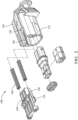
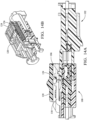
Fig. 1 is a perspective view of an electrical connector assembly in a disconnected condition according to some embodiments; -
Fig. 2 is an exploded view of one of the electrical connectors according to some embodiments; -
Fig. 3A is a cross-section side view of the electrical connector assembly during an initial stage of connection of the electrical connector assembly when a forward end of the first connector body contacts a push surface of a plunger in the second connector body according to some embodiments; -
Fig. 3B is a cut-away perspective view of the electrical connector assembly during the initial stage of connection of the electrical connector assembly shown inFig. 3A showing the condition of a spring between the second connector body and the plunger according to some embodiments; -
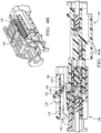
Fig. 4A is a cross-section side view of the electrical connector assembly during a stage of connection of the electrical connector assembly subsequent to the initial stage shown inFig. 3A when the plunger is moved from an engaged position toward a disengaged position according to some embodiments; -
Fig. 4B is a cut-away perspective view of the electrical connector assembly during the stage of connection of the electrical connector assembly shown inFig. 4A showing the condition of the spring between the second connector body and the plunger according to some embodiments; -
Fig. 5A is a cross-section side view of the electrical connector assembly during a stage of connection of the electrical connector assembly subsequent to the stage shown inFig. 4A when a ramp in the second connector body moves the push surface of a plunger out of contact with the forward end of the first connector body and the plunger lifts a locking arm in the second connector body over a locking fin on the first connector body while the plunger is in the disengaged position according to some embodiments; -
Fig. 5B is a cut-away perspective view of the electrical connector assembly during the stage of connection of the electrical connector assembly shown inFig. 5A showing the condition of the spring between the second connector body and the plunger according to some embodiments; -
Fig. 6A is a cross-section side view of the electrical connector assembly during a final stage of connection of the electrical connector assembly subsequent to the stage shown inFig. 5A when the plunger lowers the locking arm onto the locking fin as the plunger returns to the engaged position according to some embodiments; -
Fig. 6B is a cut-away perspective view of the electrical connector assembly during the final stage of connection of the electrical connector assembly shown inFig. 6A showing the condition of the spring between the second connector body and the plunger according to some embodiments; -
Fig. 7 is a cross-section side view of the electrical connector assembly showing a portion of the plunger that is configured to inhibit disengagement between the locking arm and the locking fin while the plunger is in the engaged position according to some embodiments; -
Fig. 8 is a cross-section side view of the electrical connector assembly showing a portion of the second connector body that forms a forward stop configured to inhibit movement of the plunger forward of the engaged position according to some embodiments; -
Fig. 9 is a cross-section side view of the electrical connector assembly during an initial stage of disconnection of the electrical connector assembly according to some embodiments; -
Fig. 10 is a cross-section side view of the electrical connector assembly during a stage of disconnection of the electrical connector assembly subsequent to the initial stage shown inFig. 9 when the plunger is moved from the engaged position toward the disengaged position according to some embodiments; -
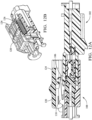
Fig. 11 is a cross-section side view of the electrical connector assembly during a stage of disconnection of the electrical connector assembly subsequent to the stage shown inFig. 10 when the plunger lifts a locking arm in the second connector body over a locking fin on the first connector body according to some embodiments; -
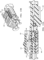
Fig. 12A is a cross-section side view of the electrical connector assembly during a stage of disconnection of the electrical connector assembly subsequent to the stage shown inFig. 11 when the plunger is in the disengaged position according to some embodiments; -
Fig. 12B is a cut-away perspective view of the electrical connector assembly during the stage of connection of the electrical connector assembly shown inFig. 12A showing the condition of the spring between the second connector body and the plunger according to some embodiments; -
Fig. 13A is a cross-section side view of the electrical connector assembly during a stage of disconnection of the electrical connector assembly subsequent to the stage shown inFig. 12A when the plunger moves toward the disengaged position as the first connector body is withdrawn from the second connector body according to some embodiments; -
Fig. 13B is a cut-away perspective view of the electrical connector assembly during the stage of disconnection of the electrical connector assembly shown inFig. 13A showing the condition of the spring between the second connector body and the plunger according to some embodiments; -
Fig. 14A is a cross-section side view of the electrical connector assembly during a stage of disconnection of the electrical connector assembly subsequent to the stage shown inFig. 13B when the plunger returns to the engaged position as the first connector body is withdrawn from the second connector body according to some embodiments; -
Fig. 14B is a cut-away perspective view of the electrical connector assembly during the stage of disconnection of the electrical connector assembly shown inFig. 14A showing the condition of the spring between the second connector body and the plunger according to some embodiments; -
Fig. 15 is a cut-away perspective view of the electrical connector assembly during the final stage of disconnection of the electrical connector assembly according to some embodiments -
Fig. 16A is a perspective view of a plunger of the electrical connector assembly according to some embodiments; -
Fig. 16B is a side view of the plunger according to some embodiments; and -
Fig. 17 is an exploded view of one of the electrical connectors according to an alternative embodiment. - This disclosure is directed to an electrical connector system in which two mating connectors are configured to self-eject or automatically separate unless completely and properly mated together. This self-ejecting feature helps to assure a proper connection is made and maintained between the mating connectors because an assembly operator is more likely to detect the separated connectors than partially mated connectors. One of the connectors includes a spring or a similar force generating device that is configured to urge the connectors apart until locking features in each of the mating connectors are properly engaged. The connector system further includes movable plunger locks and unlocks the locking features as it moved between an engaged position and a disengaged position. The plunger also includes a connector position assurance (CPA) feature that is configured to inhibit inadvertent unlocking and disconnection of the locking features when the plunger is in the engaged position. The plunger brings the spring to a relaxed condition when it is in the engaged position. The lock features can be manually disengaged using the plunger to disconnect the two mating connectors. When this occurs, the spring will urge the two mating connectors apart to break the electrical connection.
- A non-limiting example of such an
electrical connector system 100 is illustrated inFig. 1 . The electrical connector system includes afirst connector 102, in this example a male connector, having afirst connector body 104 formed of an electrically insulative material. Thefirst connector body 104 defines a lockingfin 106 near a forward edge of thefirst connector body 104. As used herein, forward and rearward directions are referenced in relation to a longitudinal axis of thefirst connector 102 in the direction in which thefirst connector 102 is inserted within asecond mating connector 108 of theelectrical connector system 100. The lockingfin 106 has an acutely angled surface relative to thefirst connector body 104 on its forward face and a perpendicular surface on its rearward face. Thesecond connector 108, in this example a female connector and shown in more detail inFig. 2 , has asecond connector body 110 that defines ashroud 112 configured to receive thefirst connector body 104. Thefirst connector 102 includes a plurality ofelectrical terminals 114 disposed within thefirst connector body 104 that are designed to mate with a plurality of corresponding matingelectrical terminals 116 disposed within thesecond connector body 110 of thesecond connector 108 as best shown inFig. 9 . - The
second connector body 110 includes aflexible locking arm 118 that is configured to releasably engage the lockingfin 106 in order to maintain a connection between the first andsecond connector bodies electrical terminals 114 in thefirst connector body 104 and the matingelectrical terminals 116 in thesecond connector body 110 of thesecond connector 108. - The
second connector 108 also includes aplunger 120 that is slidably attached to thesecond connector body 110. Theplunger 120 is moveable from an engagedposition 122 in which theplunger 120 holds thelocking arm 118 in engagement with the lockingfin 106 to adisengaged position 124 in which theplunger 120 disengages thelocking arm 118 from the lockingfin 106. - The
second connector 108 further includes a pair ofcompression coil springs 126 disposed between theplunger 120 and thesecond connector body 110. Thesesprings 126 are configured to urge theplunger 120 into the engagedposition 122. In alternative embodiments, these springs may be replaced by other types of springs that urge theplunger 120 into the engagedposition 122, for example leaf compression springs, polymeric compression springs, pneumatic compression springs, or extension springs. Apush surface 128 on a fore end of aflexible arm 130 of theplunger 120 contacts aforward end 132 of thefirst connector body 104 as thefirst connector body 104 is inserted within thesecond connector body 110, thereby compressing thesprings 126 and moving theplunger 120 from the engagedposition 122 to thedisengaged position 124 as shown inFigs. 3A and4A . The compression of thesprings 126 exert a force between the first andsecond connector bodies second connectors second connectors second connectors second connector 108 in the direction in which thesecond connector 108 is mated with thefirst connector 102. - A
portion 134 of theflexible arm 130, best illustrated inFig. 16A and 16B , is disposed within aguide channel 136 in thesecond connector body 110 and a rearward end of thisguide channel 136 defines anangled ramp feature 138. When theplunger 120 is pulled back to thedisengaged position 124 as shown inFig. 5A , theramp feature 138 bends theflexible arm 130 upward so that thepush surface 128 no longer contacts theforward end 132 of thefirst connector body 104 as shown inFig. 6A . This allows theplunger 120 to return from thedisengaged position 124 toward the engagedposition 122. - As shown in
Fig. 4A , theplunger 120 defines afirst tab 140 having a firstangled surface 142 on its aft end and thelocking arm 118 defines asecond tab 144 having a secondangled surface 146 on its fore end. As shown inFig. 4A , the firstangled surface 142 contacts the secondangled surface 146 as theplunger 120 moves from the engagedposition 122 to thedisengaged position 124 and lifts the forward end of thelocking arm 118 over the lockingfin 106 of thefirst connector body 104. Thefirst tab 140 lifts and holds the fore end of thelocking arm 118 over the lockingfin 106 when theplunger 120 is in thedisengaged position 124, thereby disengaging thelocking arm 118 from the lockingfin 106 and allowing thefirst connector body 104 to be separated and removed from thesecond connector body 110. - The locking
arm 118 defines anaperture 148 in which the lockingfin 106 is received after theplunger 120 is moved from thedisengaged position 124 the engagedposition 122 and thefirst tab 140 is no longer engaged with thesecond tab 144 as shown inFig. 7 . - The
springs 126 are compressed when theplunger 120 is moved from the engagedposition 122 to thedisengaged position 124 and are relaxed when theplunger 120 is in the engagedposition 122 as shown inFigs 3B ,4B ,5B , and6B . - The
plunger 120 and thesecond connector body 110 are formed of a polymeric material. In an alternative embodiment shown inFig. 17 , theelectrical connector system 100 further comprises ametallic clip 150 that is disposed within thesecond connector body 110. Thesprings 126 are disposed between theplunger 120 and themetallic clip 150. The metallic clip provides the benefit of reducing the amount of polymer creep in thesecond connector body 110 that may occur over time. - A
portion 152 of theplunger 120 is configured to block upward movement of thelocking arm 118 when theplunger 120 is in the engagedposition 122, thereby providing a connector position assurance function. - The
forward end 154 of theplunger 120 may contact thesecond connector body 110 to prevent theplunger 120 from moving beyond the engagedposition 122 as illustrated inFig. 8 . - A method of connecting the electrical connector system described above includes the steps of :
- inserting the
second connector body 110 within thefirst connector body 104 as shown inFig. 3A ; - moving the
plunger 120 from the engagedposition 122 to thedisengaged position 124 via contact between apush surface 128 on aflexible arm 130 of theplunger 120 and aforward end 132 of thefirst connector body 104 as thefirst connector body 104 is inserted within thesecond connector body 110 as shown inFigs 4A and5A ; - compressing the
springs 126 as theplunger 120 moves from the engagedposition 122 to thedisengaged position 124, thereby exerting a force on theforward end 132 of thefirst connector body 104 and urging the first andsecond connector bodies Figs. 4B and5B ; - lifting the
flexible locking arm 118 over the lockingfin 106 as theplunger 120 moves from the engagedposition 122 to thedisengaged position 124 as shown inFig. 5A ; - bending the
flexible arm 130 such that thepush surface 128 no longer contacts theforward end 132 of thefirst connector body 104 as theplunger 120 reaches thedisengaged position 124 as shown inFig. 5A ; - moving the
plunger 120 from thedisengaged position 124 to the engagedposition 122 as thesprings 126 decompress because thepush surface 128 is no longer in contact with theforward end 132 as shown inFigs. 6A and 6B ; and - lowering the
locking arm 118 over the lockingfin 106 such that the lockingfin 106 is received within anaperture 148 within the lockingarm 118 as theplunger 120 moves back to the engagedposition 122, thereby securing thefirst connector body 104 to thesecond connector body 110 as shown inFig. 6A . - The method also may include the step of blocking upward movement of the
locking arm 118 by positioning aportion 152 of theplunger 120 over the lockingarm 118 when theplunger 120 is in the engagedposition 122, thereby providing connector position assurance as shown inFig. 7 . - The
springs 126 are compressed as theplunger 120 is moved from the engagedposition 122 and are relaxed when theplunger 120 is in the engagedposition 122 as shown inFigs. 3B ,4B ,5B , and6B . - A method of disconnecting the electrical connector system described above includes the steps of:
- moving the
plunger 120 from the engagedposition 122 to thedisengaged position 124 as shown inFigs. 9 and 10 ; - lifting the
flexible locking arm 118 over the lockingfin 106 as theplunger 120 moves from the engagedposition 122 to thedisengaged position 124 as shown inFig. 11 ; - compressing the
springs 126 as theplunger 120 moves from the engagedposition 122 to thedisengaged position 124 as shown inFig. 12B ; - withdrawing the
first connector body 104 from thesecond connector body 110 as shown inFig. 14A and15 ; and - moving the
plunger 120 from thedisengaged position 124 to the engagedposition 122 as thesprings 126 decompress as shown inFigs. 12A, 12B ,13A, 13B ,14A, and 14B , thereby separating thefirst connector body 104 from thesecond connector body 110 via contact between apush surface 128 on aflexible arm 130 of theplunger 120 and aforward end 132 of thefirst connector body 104. - The
springs 126 are compressed as theplunger 120 is moved from the engagedposition 122 and relaxed when theplunger 120 is in the engagedposition 122 as shown inFigs. 12B ,13B , and14B . - While the invention has been described with reference to an exemplary embodiment(s), it will be understood by those skilled in the art that various changes may be made, and equivalents may be substituted for elements thereof without departing from the scope of the invention. In addition, many modifications may be made to adapt a particular situation or material to the teachings of the invention without departing from the essential scope thereof. Therefore, it is intended that the invention is not limited to the disclosed embodiment(s), but that the invention will include all embodiments falling within the scope of the appended claims.
- As used herein, 'one or more' includes a function being performed by one element, a function being performed by more than one element, e.g., in a distributed fashion, several functions being performed by one element, several functions being performed by several elements, or any combination of the above.
- It will also be understood that, although the terms first, second, etc. are, in some instances, used herein to describe various elements, these elements should not be limited by these terms. These terms are only used to distinguish one element from another. For example, a first contact could be termed a second contact, and, similarly, a second contact could be termed a first contact, without departing from the scope of the various described embodiments. The first contact and the second contact are both contacts, but they are not the same contact.
- The terminology used in the description of the various described embodiments herein is for the purpose of describing particular embodiments only and is not intended to be limiting. As used in the description of the various described embodiments and the appended claims, the singular forms "a", "an" and "the" are intended to include the plural forms as well, unless the context clearly indicates otherwise. It will also be understood that the term "and/or" as used herein refers to and encompasses any and all possible combinations of one or more of the associated listed items. It will be further understood that the terms "includes," "including," "comprises," and/or "comprising," when used in this specification, specify the presence of stated features, integers, steps, operations, elements, and/or components, but do not preclude the presence or addition of one or more other features, integers, steps, operations, elements, components, and/or groups thereof.
- As used herein, the term "if' is, optionally, construed to mean "when" or "upon" or "in response to determining" or "in response to detecting," depending on the context. Similarly, the phrase "if it is determined" or "if [a stated condition or event] is detected" is, optionally, construed to mean "upon determining" or "in response to determining" or "upon detecting [the stated condition or event]" or "in response to detecting [the stated condition or event]," depending on the context.
- Additionally, while terms of ordinance or orientation may be used herein these elements should not be limited by these terms. All terms of ordinance or orientation, unless stated otherwise, are used for purposes distinguishing one element from another, and do not denote any particular order, order of operations, direction or orientation unless stated otherwise.
Claims (15)
- An electrical connector system (100), comprising:a first connector body (104) defining a locking fin (106);a second connector body (110) configured to receive the first connector body (104);a flexible locking arm (118) defined by the second connector body (110) configured to releasably engage the locking fin (106);a plunger (120) slidably attached to the second connector body (110) and moveable from an engaged position (122) in which the plunger (120) holds the locking arm (118) in engagement with the locking fin (106) to a disengaged position (124) in which the plunger (120) disengages the locking arm (118) from the locking fin (106); anda spring (126) disposed between the plunger (120) and the second connector body (110) and configured to urge the plunger (120) into the engaged position (122).
- The electrical connector system (100) according to claim 1, a push surface (128) on a flexible arm (130) of the plunger (120) contacts a forward end (132) of the first connector body (104) as the first connector body (104) is inserted within the second connector body (110), thereby compressing the spring (126) and moving the plunger (120) from the engaged position (122) to the disengaged position (124).
- The electrical connector system (100) according to claim 2, wherein the second connector body (110) is configured to bend the flexible arm (130) such that the push surface (128) no longer contacts the forward end (132) of the first connector body (104) as the plunger (120) reaches the disengaged position (124), thereby allowing the plunger (120) to return from the disengaged position (124) to the engaged position (122).
- The electrical connector system (100) according to claim 2 or 3, wherein compression of the spring (126) causes the push surface (128) on the flexible arm (130) of the plunger (120) to exert a force on the forward end (132) of the first connector body (104) when the push surface (128) is in contact with the forward end (132), thereby urging the first and second connector bodies (104, 110) apart.
- The electrical connector system (100) according to any one of claims 2 to 4, wherein the second connector body (110) defines a guide channel (136) in which a portion (134) of the flexible arm (130) is disposed and wherein the guide channel (136) defines a ramp surface (138) configured to bend the flexible arm (130) such that the push surface (128) no longer contacts the forward end (132) of the first connector body (104) as the plunger (120) reaches the disengaged position (124).
- The electrical connector system (100) according to any one of the preceding claims, wherein the plunger (120) defines a first tab (140) having a first angled surface (142) and the locking arm (118) defines a second tab (144) having a second angled surface (146) and wherein the first angled surface (142) contacts the second angled surface (146) as the plunger (120) moves from the engaged position (122) to the disengaged position (124), thereby lifting an end of the locking arm (118) over the locking fin (106).
- The electrical connector system (100 according to claim 6, wherein the first tab (140) holds the end of the locking arm (118) over the locking fin (106) when the plunger (120 is in the disengaged position (124).
- The electrical connector system (100) according to any one of the preceding claims, wherein the plunger (120) is configured to lift the locking arm (118) over the locking fin (106) when the plunger (120) is in the disengaged position (124).
- The electrical connector system (100) according to any one of the preceding claims, wherein the locking arm (118) defines an aperture (148) in which the locking fin (106) is received when the plunger (120) is in the engaged position (122).
- The electrical connector system (100) according to any one of the preceding claims, wherein the plunger (120) and the second connector body (110) are formed of a polymeric material, wherein the electrical connector system (100) further comprises a metallic clip (150) disposed within the second connector body (110), and wherein the spring (126) is disposed between the plunger (120) and the metallic clip (150).
- The electrical connector system (100) according to any one of the preceding claims, wherein the spring (126) is compressed when the plunger (120) is moved from the engaged position (122) to the disengaged position (124).
- The electrical connector system (100) according to any one of the preceding claims, wherein the spring (126) is relaxed when the plunger (120) is in the engaged position (122).
- The electrical connector system (100) according to any one of the preceding claims, wherein a portion (152) of the plunger (120) blocks upward movement of the locking arm (118) when the plunger (120) is in the engaged position (120), thereby providing connector position assurance.
- A method of connecting an electrical connector system (100) which includes:a first connector body (104) defining a locking fin (106);a second connector body (110) configured to receive the first connector body (104);a flexible locking arm (118) defined by the second connector body (110) configured to releasably engage the locking fin (106);a plunger (120) slidably attached to the second connector body (110) and moveable from an engaged position (122) in which the plunger (120) holds the locking arm (118) in engagement with the locking fin (106) to a disengaged position (124) in which the plunger (120) disengages the locking arm (118) from the locking fin (106); anda spring (126) disposed between the plunger (120) and the second connector body (110) and configured to urge the plunger (120) into the engaged position (122), said method comprising;inserting the second connector body (110) within the first connector body (104);moving the plunger (120) from the engaged position (122) to the disengaged position (124) via contact between a push surface (128) on a flexible arm (130) of the plunger (120) and a forward end (132) of the first connector body (104) as the first connector body (104) is inserted within the second connector body (110);compressing the spring (126) as the plunger (120) moves from the engaged position (122) to the disengaged position (124), thereby exerting a force on the forward end (132) of the first connector body (104) and urging the first and second connector bodies (104, 110) apart;lifting the flexible locking arm (118) over the locking fin (106) as the plunger (120) moves from the engaged position (122) to the disengaged position (122);bending the flexible arm (130) such that the push surface (128) no longer contacts the forward end (132) of the first connector body (104) as the plunger (120) reaches the disengaged position (122);moving the plunger (120) from the disengaged position (124) to the engaged position (122) as the spring (126) decompresses because the push surface (128) is no longer in contact with the forward end (132); andlowering the locking arm (118) over the locking fin (106) such that the locking fin (106) is received within an aperture (148) within the locking arm (118) as the plunger (120) moves back to the engaged position (122), thereby securing the first connector body (104) to the second connector body (110).
- A method of disconnecting an electrical connector system (100) which includes:a first connector body (104) defining a locking fin (106);
a second connector body (110) configured to receive the first connector body (104);a flexible locking arm (118) defined by the second connector body (110) configured to releasably engage the locking fin (106);a plunger (120) slidably attached to the second connector body (110) and moveable from an engaged position (122) in which the plunger (120) holds the locking arm (118) in engagement with the locking fin (106) to a disengaged position (124) in which the plunger (120) disengages the locking arm (118) from the locking fin (106); anda spring (126) disposed between the plunger (120) and the second connector body (110) and configured to urge the plunger (120) into the engaged position (122), said method comprising;moving the plunger (120) from the engaged position (122) to the disengaged position (124);lifting the flexible locking arm (118) over the locking fin (104) as the plunger (120) moves from the engaged position (122) to the disengaged position (124);compressing the spring (126) as the plunger (120) moves from the engaged position (122) to the disengaged position (124);withdrawing the first connector body (104) from the second connector body (110); andmoving the plunger (120) from the disengaged position (124) to the engaged position (122) as the spring (126) decompresses, thereby separating the first connector body (104) from the second connector body (110) via contact between a push surface (128) on a flexible arm (130) of the plunger (120) and a forward end (132) of the first connector body (104).
Applications Claiming Priority (2)
| Application Number | Priority Date | Filing Date | Title |
|---|---|---|---|
| US202163227117P | 2021-07-29 | 2021-07-29 | |
| US17/588,955 US11876324B2 (en) | 2021-07-29 | 2022-01-31 | Self-ejecting electrical connection system |
Publications (2)
| Publication Number | Publication Date |
|---|---|
| EP4125163A1 true EP4125163A1 (en) | 2023-02-01 |
| EP4125163B1 EP4125163B1 (en) | 2024-08-28 |
Family
ID=82781105
Family Applications (1)
| Application Number | Title | Priority Date | Filing Date |
|---|---|---|---|
| EP22187549.5A Active EP4125163B1 (en) | 2021-07-29 | 2022-07-28 | Self-ejecting electrical connection system |
Country Status (3)
| Country | Link |
|---|---|
| US (1) | US11876324B2 (en) |
| EP (1) | EP4125163B1 (en) |
| CN (1) | CN115693281B (en) |
Citations (4)
| Publication number | Priority date | Publication date | Assignee | Title |
|---|---|---|---|---|
| US20040038569A1 (en) * | 2002-08-22 | 2004-02-26 | Sumitomo Wiring Systems, Ltd. | Connector and a connector assembly |
| EP1411597B1 (en) * | 2002-10-18 | 2008-09-10 | Yazaki Europe Ltd. | Plug connector for connecting to a socket |
| DE102005044148B4 (en) * | 2004-09-17 | 2009-08-06 | Sumitomo Wiring Systems, Ltd., Yokkaichi | Connector and connector assembly |
| EP3211728B1 (en) * | 2016-02-26 | 2020-10-28 | Tyco Electronics France SAS | Electrical connector system comprising a locking assurance device |
Family Cites Families (27)
| Publication number | Priority date | Publication date | Assignee | Title |
|---|---|---|---|---|
| JPS6071084U (en) * | 1983-10-24 | 1985-05-20 | 星電器製造株式会社 | Connector with lock mechanism |
| JPH0244270U (en) * | 1988-09-21 | 1990-03-27 | ||
| JPH04133373U (en) * | 1991-05-31 | 1992-12-11 | 第一電子工業株式会社 | electrical connectors |
| JP3036419B2 (en) * | 1995-11-17 | 2000-04-24 | 住友電装株式会社 | Half mating detection connector |
| JP3155189B2 (en) * | 1996-02-09 | 2001-04-09 | 住友電装株式会社 | connector |
| JP3285307B2 (en) * | 1996-03-07 | 2002-05-27 | 矢崎総業株式会社 | Half mating prevention connector |
| JP3468451B2 (en) * | 1997-09-09 | 2003-11-17 | 矢崎総業株式会社 | Connector mating structure |
| JP3278051B2 (en) * | 1997-12-25 | 2002-04-30 | 住友電装株式会社 | Connector with cover |
| JP3437102B2 (en) * | 1998-10-22 | 2003-08-18 | 矢崎総業株式会社 | Half mating prevention connector |
| US6312277B1 (en) * | 1999-01-27 | 2001-11-06 | Cardell Corporation | Connector position assurance device for a connector |
| JP3817118B2 (en) * | 1999-09-20 | 2006-08-30 | 矢崎総業株式会社 | Half-mating prevention connector |
| JP3593959B2 (en) * | 2000-08-10 | 2004-11-24 | 住友電装株式会社 | connector |
| JP3656830B2 (en) * | 2001-02-16 | 2005-06-08 | 住友電装株式会社 | connector |
| US6948956B2 (en) | 2003-05-28 | 2005-09-27 | Fci Americas Technology, Inc. | Electrical connector with module ejection system |
| JP4306573B2 (en) * | 2004-09-17 | 2009-08-05 | 住友電装株式会社 | connector |
| CN101180772B (en) * | 2005-05-24 | 2010-12-08 | Fci公司 | Electrical connector with improved releasable locking device |
| JP2007335328A (en) * | 2006-06-16 | 2007-12-27 | Sumitomo Wiring Syst Ltd | Fitting member |
| SG143088A1 (en) * | 2006-11-22 | 2008-06-27 | Mea Technologies Pte Ltd | Electrical connector |
| WO2009130529A1 (en) * | 2008-04-24 | 2009-10-29 | Fci | Connector |
| US7758370B1 (en) * | 2009-06-26 | 2010-07-20 | Corning Gilbert Inc. | Quick release electrical connector |
| JP5728245B2 (en) * | 2011-02-21 | 2015-06-03 | 矢崎総業株式会社 | connector |
| US8905795B2 (en) | 2011-10-12 | 2014-12-09 | Apple Inc. | Spring-loaded contacts |
| EP2840664B1 (en) * | 2013-08-20 | 2016-06-08 | Delphi Technologies, Inc. | Connector assembly with spring operated secondary lock |
| US9466916B2 (en) | 2014-05-21 | 2016-10-11 | Schlumberger Technology Corporation | Multi-contact connector assembly |
| US10135189B2 (en) * | 2015-09-02 | 2018-11-20 | J.S.T. Corporation | Connector apparatus having male and female connector assemblies and a connector position assurance device, a male connector assembly, a female connector assembly, and a method for assembling the connector apparatus |
| US20190260150A1 (en) | 2018-02-19 | 2019-08-22 | Te Connectivity Corporation | Electrical power connector assembly |
| JP7386523B2 (en) * | 2020-02-06 | 2023-11-27 | 日本圧着端子製造株式会社 | connector lock mechanism |
-
2022
- 2022-01-31 US US17/588,955 patent/US11876324B2/en active Active
- 2022-07-28 EP EP22187549.5A patent/EP4125163B1/en active Active
- 2022-07-28 CN CN202210897127.2A patent/CN115693281B/en active Active
Patent Citations (4)
| Publication number | Priority date | Publication date | Assignee | Title |
|---|---|---|---|---|
| US20040038569A1 (en) * | 2002-08-22 | 2004-02-26 | Sumitomo Wiring Systems, Ltd. | Connector and a connector assembly |
| EP1411597B1 (en) * | 2002-10-18 | 2008-09-10 | Yazaki Europe Ltd. | Plug connector for connecting to a socket |
| DE102005044148B4 (en) * | 2004-09-17 | 2009-08-06 | Sumitomo Wiring Systems, Ltd., Yokkaichi | Connector and connector assembly |
| EP3211728B1 (en) * | 2016-02-26 | 2020-10-28 | Tyco Electronics France SAS | Electrical connector system comprising a locking assurance device |
Also Published As
| Publication number | Publication date |
|---|---|
| CN115693281B (en) | 2026-03-10 |
| US11876324B2 (en) | 2024-01-16 |
| EP4125163B1 (en) | 2024-08-28 |
| CN115693281A (en) | 2023-02-03 |
| US20230030374A1 (en) | 2023-02-02 |
Similar Documents
| Publication | Publication Date | Title |
|---|---|---|
| US6533600B1 (en) | Connector fitting construction | |
| US5628649A (en) | Lock detecting structure of connector | |
| US11881650B2 (en) | Electrical connector assembly with male terminal stabilizer | |
| EP2503648B1 (en) | Connector position assurance device | |
| CN101453083B (en) | Connector | |
| EP2975698B1 (en) | Electrical connector with a terminal position assurance device | |
| US6386898B1 (en) | Connector fitting construction | |
| US6241542B1 (en) | Connector with shorting terminal | |
| EP2871722A2 (en) | Terminal position assurance with dual primary lock reinforcement and independent secondary lock | |
| US10340618B1 (en) | Electrical terminal housing with releasable terminal locks | |
| EP1571734A1 (en) | Connector apparatus with a mating detecting member called connector position assurance | |
| US6685500B2 (en) | Connector and a method of assembling a connector | |
| US11502444B2 (en) | Electrical connector assembly having a male blade stabilizer with integrated primary lock reinforcement | |
| US9362652B2 (en) | Connector with at least one detector | |
| US6206717B1 (en) | Connector | |
| US6685506B1 (en) | Connector and a method for connecting such connector with a mating connector | |
| US11581680B2 (en) | Spring loaded self-ejecting connector | |
| EP4297193A1 (en) | Electrical connector assembly with flexible and rigid terminal locking features | |
| US6224414B1 (en) | Half-fitting prevention connector | |
| US11876324B2 (en) | Self-ejecting electrical connection system | |
| US6971906B2 (en) | Connector and a connector assembly | |
| US20200328551A1 (en) | Electric terminal housing with a terminal lock | |
| US6494733B2 (en) | Connector | |
| US6722913B2 (en) | Connector | |
| CN110323636B (en) | Connector Components and Connectors |
Legal Events
| Date | Code | Title | Description |
|---|---|---|---|
| PUAI | Public reference made under article 153(3) epc to a published international application that has entered the european phase |
Free format text: ORIGINAL CODE: 0009012 |
|
| STAA | Information on the status of an ep patent application or granted ep patent |
Free format text: STATUS: THE APPLICATION HAS BEEN PUBLISHED |
|
| STAA | Information on the status of an ep patent application or granted ep patent |
Free format text: STATUS: REQUEST FOR EXAMINATION WAS MADE |
|
| AK | Designated contracting states |
Kind code of ref document: A1 Designated state(s): AL AT BE BG CH CY CZ DE DK EE ES FI FR GB GR HR HU IE IS IT LI LT LU LV MC MK MT NL NO PL PT RO RS SE SI SK SM TR |
|
| 17P | Request for examination filed |
Effective date: 20230119 |
|
| RBV | Designated contracting states (corrected) |
Designated state(s): AL AT BE BG CH CY CZ DE DK EE ES FI FR GB GR HR HU IE IS IT LI LT LU LV MC MK MT NL NO PL PT RO RS SE SI SK SM TR |
|
| RAP3 | Party data changed (applicant data changed or rights of an application transferred) |
Owner name: APTIV TECHNOLOGIES LIMITED |
|
| RAP1 | Party data changed (applicant data changed or rights of an application transferred) |
Owner name: APTIV TECHNOLOGIES AG |
|
| GRAP | Despatch of communication of intention to grant a patent |
Free format text: ORIGINAL CODE: EPIDOSNIGR1 |
|
| STAA | Information on the status of an ep patent application or granted ep patent |
Free format text: STATUS: GRANT OF PATENT IS INTENDED |
|
| GRAS | Grant fee paid |
Free format text: ORIGINAL CODE: EPIDOSNIGR3 |
|
| INTG | Intention to grant announced |
Effective date: 20240620 |
|
| GRAA | (expected) grant |
Free format text: ORIGINAL CODE: 0009210 |
|
| STAA | Information on the status of an ep patent application or granted ep patent |
Free format text: STATUS: THE PATENT HAS BEEN GRANTED |
|
| AK | Designated contracting states |
Kind code of ref document: B1 Designated state(s): AL AT BE BG CH CY CZ DE DK EE ES FI FR GB GR HR HU IE IS IT LI LT LU LV MC MK MT NL NO PL PT RO RS SE SI SK SM TR |
|
| P01 | Opt-out of the competence of the unified patent court (upc) registered |
Free format text: CASE NUMBER: APP_43180/2024 Effective date: 20240723 |
|
| REG | Reference to a national code |
Ref country code: CH Ref legal event code: EP |
|
| REG | Reference to a national code |
Ref country code: DE Ref legal event code: R096 Ref document number: 602022005643 Country of ref document: DE |
|
| RAP4 | Party data changed (patent owner data changed or rights of a patent transferred) |
Owner name: APTIV TECHNOLOGIES AG |
|
| REG | Reference to a national code |
Ref country code: IE Ref legal event code: FG4D |
|
| REG | Reference to a national code |
Ref country code: LT Ref legal event code: MG9D |
|
| PG25 | Lapsed in a contracting state [announced via postgrant information from national office to epo] |
Ref country code: NO Free format text: LAPSE BECAUSE OF FAILURE TO SUBMIT A TRANSLATION OF THE DESCRIPTION OR TO PAY THE FEE WITHIN THE PRESCRIBED TIME-LIMIT Effective date: 20241128 |
|
| REG | Reference to a national code |
Ref country code: AT Ref legal event code: MK05 Ref document number: 1719036 Country of ref document: AT Kind code of ref document: T Effective date: 20240828 |
|
| PG25 | Lapsed in a contracting state [announced via postgrant information from national office to epo] |
Ref country code: FI Free format text: LAPSE BECAUSE OF FAILURE TO SUBMIT A TRANSLATION OF THE DESCRIPTION OR TO PAY THE FEE WITHIN THE PRESCRIBED TIME-LIMIT Effective date: 20240828 Ref country code: NL Free format text: LAPSE BECAUSE OF FAILURE TO SUBMIT A TRANSLATION OF THE DESCRIPTION OR TO PAY THE FEE WITHIN THE PRESCRIBED TIME-LIMIT Effective date: 20240828 Ref country code: PL Free format text: LAPSE BECAUSE OF FAILURE TO SUBMIT A TRANSLATION OF THE DESCRIPTION OR TO PAY THE FEE WITHIN THE PRESCRIBED TIME-LIMIT Effective date: 20240828 Ref country code: GR Free format text: LAPSE BECAUSE OF FAILURE TO SUBMIT A TRANSLATION OF THE DESCRIPTION OR TO PAY THE FEE WITHIN THE PRESCRIBED TIME-LIMIT Effective date: 20241129 Ref country code: PT Free format text: LAPSE BECAUSE OF FAILURE TO SUBMIT A TRANSLATION OF THE DESCRIPTION OR TO PAY THE FEE WITHIN THE PRESCRIBED TIME-LIMIT Effective date: 20241230 |
|
| PG25 | Lapsed in a contracting state [announced via postgrant information from national office to epo] |
Ref country code: BG Free format text: LAPSE BECAUSE OF FAILURE TO SUBMIT A TRANSLATION OF THE DESCRIPTION OR TO PAY THE FEE WITHIN THE PRESCRIBED TIME-LIMIT Effective date: 20240828 |
|
| PG25 | Lapsed in a contracting state [announced via postgrant information from national office to epo] |
Ref country code: LV Free format text: LAPSE BECAUSE OF FAILURE TO SUBMIT A TRANSLATION OF THE DESCRIPTION OR TO PAY THE FEE WITHIN THE PRESCRIBED TIME-LIMIT Effective date: 20240828 |
|
| REG | Reference to a national code |
Ref country code: NL Ref legal event code: MP Effective date: 20240828 |
|
| PG25 | Lapsed in a contracting state [announced via postgrant information from national office to epo] |
Ref country code: IS Free format text: LAPSE BECAUSE OF FAILURE TO SUBMIT A TRANSLATION OF THE DESCRIPTION OR TO PAY THE FEE WITHIN THE PRESCRIBED TIME-LIMIT Effective date: 20241228 Ref country code: AT Free format text: LAPSE BECAUSE OF FAILURE TO SUBMIT A TRANSLATION OF THE DESCRIPTION OR TO PAY THE FEE WITHIN THE PRESCRIBED TIME-LIMIT Effective date: 20240828 |
|
| PG25 | Lapsed in a contracting state [announced via postgrant information from national office to epo] |
Ref country code: HR Free format text: LAPSE BECAUSE OF FAILURE TO SUBMIT A TRANSLATION OF THE DESCRIPTION OR TO PAY THE FEE WITHIN THE PRESCRIBED TIME-LIMIT Effective date: 20240828 |
|
| PG25 | Lapsed in a contracting state [announced via postgrant information from national office to epo] |
Ref country code: ES Free format text: LAPSE BECAUSE OF FAILURE TO SUBMIT A TRANSLATION OF THE DESCRIPTION OR TO PAY THE FEE WITHIN THE PRESCRIBED TIME-LIMIT Effective date: 20240828 Ref country code: RS Free format text: LAPSE BECAUSE OF FAILURE TO SUBMIT A TRANSLATION OF THE DESCRIPTION OR TO PAY THE FEE WITHIN THE PRESCRIBED TIME-LIMIT Effective date: 20241128 |
|
| PG25 | Lapsed in a contracting state [announced via postgrant information from national office to epo] |
Ref country code: RS Free format text: LAPSE BECAUSE OF FAILURE TO SUBMIT A TRANSLATION OF THE DESCRIPTION OR TO PAY THE FEE WITHIN THE PRESCRIBED TIME-LIMIT Effective date: 20241128 Ref country code: PT Free format text: LAPSE BECAUSE OF FAILURE TO SUBMIT A TRANSLATION OF THE DESCRIPTION OR TO PAY THE FEE WITHIN THE PRESCRIBED TIME-LIMIT Effective date: 20241230 Ref country code: PL Free format text: LAPSE BECAUSE OF FAILURE TO SUBMIT A TRANSLATION OF THE DESCRIPTION OR TO PAY THE FEE WITHIN THE PRESCRIBED TIME-LIMIT Effective date: 20240828 Ref country code: NO Free format text: LAPSE BECAUSE OF FAILURE TO SUBMIT A TRANSLATION OF THE DESCRIPTION OR TO PAY THE FEE WITHIN THE PRESCRIBED TIME-LIMIT Effective date: 20241128 Ref country code: NL Free format text: LAPSE BECAUSE OF FAILURE TO SUBMIT A TRANSLATION OF THE DESCRIPTION OR TO PAY THE FEE WITHIN THE PRESCRIBED TIME-LIMIT Effective date: 20240828 Ref country code: LV Free format text: LAPSE BECAUSE OF FAILURE TO SUBMIT A TRANSLATION OF THE DESCRIPTION OR TO PAY THE FEE WITHIN THE PRESCRIBED TIME-LIMIT Effective date: 20240828 Ref country code: IS Free format text: LAPSE BECAUSE OF FAILURE TO SUBMIT A TRANSLATION OF THE DESCRIPTION OR TO PAY THE FEE WITHIN THE PRESCRIBED TIME-LIMIT Effective date: 20241228 Ref country code: HR Free format text: LAPSE BECAUSE OF FAILURE TO SUBMIT A TRANSLATION OF THE DESCRIPTION OR TO PAY THE FEE WITHIN THE PRESCRIBED TIME-LIMIT Effective date: 20240828 Ref country code: GR Free format text: LAPSE BECAUSE OF FAILURE TO SUBMIT A TRANSLATION OF THE DESCRIPTION OR TO PAY THE FEE WITHIN THE PRESCRIBED TIME-LIMIT Effective date: 20241129 Ref country code: FI Free format text: LAPSE BECAUSE OF FAILURE TO SUBMIT A TRANSLATION OF THE DESCRIPTION OR TO PAY THE FEE WITHIN THE PRESCRIBED TIME-LIMIT Effective date: 20240828 Ref country code: ES Free format text: LAPSE BECAUSE OF FAILURE TO SUBMIT A TRANSLATION OF THE DESCRIPTION OR TO PAY THE FEE WITHIN THE PRESCRIBED TIME-LIMIT Effective date: 20240828 Ref country code: BG Free format text: LAPSE BECAUSE OF FAILURE TO SUBMIT A TRANSLATION OF THE DESCRIPTION OR TO PAY THE FEE WITHIN THE PRESCRIBED TIME-LIMIT Effective date: 20240828 Ref country code: AT Free format text: LAPSE BECAUSE OF FAILURE TO SUBMIT A TRANSLATION OF THE DESCRIPTION OR TO PAY THE FEE WITHIN THE PRESCRIBED TIME-LIMIT Effective date: 20240828 |
|
| PG25 | Lapsed in a contracting state [announced via postgrant information from national office to epo] |
Ref country code: RO Free format text: LAPSE BECAUSE OF FAILURE TO SUBMIT A TRANSLATION OF THE DESCRIPTION OR TO PAY THE FEE WITHIN THE PRESCRIBED TIME-LIMIT Effective date: 20240828 Ref country code: DK Free format text: LAPSE BECAUSE OF FAILURE TO SUBMIT A TRANSLATION OF THE DESCRIPTION OR TO PAY THE FEE WITHIN THE PRESCRIBED TIME-LIMIT Effective date: 20240828 Ref country code: SM Free format text: LAPSE BECAUSE OF FAILURE TO SUBMIT A TRANSLATION OF THE DESCRIPTION OR TO PAY THE FEE WITHIN THE PRESCRIBED TIME-LIMIT Effective date: 20240828 |
|
| PG25 | Lapsed in a contracting state [announced via postgrant information from national office to epo] |
Ref country code: EE Free format text: LAPSE BECAUSE OF FAILURE TO SUBMIT A TRANSLATION OF THE DESCRIPTION OR TO PAY THE FEE WITHIN THE PRESCRIBED TIME-LIMIT Effective date: 20240828 |
|
| PG25 | Lapsed in a contracting state [announced via postgrant information from national office to epo] |
Ref country code: CZ Free format text: LAPSE BECAUSE OF FAILURE TO SUBMIT A TRANSLATION OF THE DESCRIPTION OR TO PAY THE FEE WITHIN THE PRESCRIBED TIME-LIMIT Effective date: 20240828 |
|
| PG25 | Lapsed in a contracting state [announced via postgrant information from national office to epo] |
Ref country code: IT Free format text: LAPSE BECAUSE OF FAILURE TO SUBMIT A TRANSLATION OF THE DESCRIPTION OR TO PAY THE FEE WITHIN THE PRESCRIBED TIME-LIMIT Effective date: 20240828 Ref country code: SK Free format text: LAPSE BECAUSE OF FAILURE TO SUBMIT A TRANSLATION OF THE DESCRIPTION OR TO PAY THE FEE WITHIN THE PRESCRIBED TIME-LIMIT Effective date: 20240828 |
|
| REG | Reference to a national code |
Ref country code: DE Ref legal event code: R097 Ref document number: 602022005643 Country of ref document: DE |
|
| PLBE | No opposition filed within time limit |
Free format text: ORIGINAL CODE: 0009261 |
|
| STAA | Information on the status of an ep patent application or granted ep patent |
Free format text: STATUS: NO OPPOSITION FILED WITHIN TIME LIMIT |
|
| 26N | No opposition filed |
Effective date: 20250530 |
|
| PG25 | Lapsed in a contracting state [announced via postgrant information from national office to epo] |
Ref country code: SE Free format text: LAPSE BECAUSE OF FAILURE TO SUBMIT A TRANSLATION OF THE DESCRIPTION OR TO PAY THE FEE WITHIN THE PRESCRIBED TIME-LIMIT Effective date: 20240828 |
|
| PGFP | Annual fee paid to national office [announced via postgrant information from national office to epo] |
Ref country code: DE Payment date: 20250618 Year of fee payment: 4 |
|
| PGFP | Annual fee paid to national office [announced via postgrant information from national office to epo] |
Ref country code: FR Payment date: 20250703 Year of fee payment: 4 |
|
| REG | Reference to a national code |
Ref country code: CH Ref legal event code: H13 Free format text: ST27 STATUS EVENT CODE: U-0-0-H10-H13 (AS PROVIDED BY THE NATIONAL OFFICE) Effective date: 20260224 |
|
| PG25 | Lapsed in a contracting state [announced via postgrant information from national office to epo] |
Ref country code: LU Free format text: LAPSE BECAUSE OF NON-PAYMENT OF DUE FEES Effective date: 20250728 |
|
| REG | Reference to a national code |
Ref country code: BE Ref legal event code: MM Effective date: 20250731 |
|
| PG25 | Lapsed in a contracting state [announced via postgrant information from national office to epo] |
Ref country code: BE Free format text: LAPSE BECAUSE OF NON-PAYMENT OF DUE FEES Effective date: 20250731 |
|
| PG25 | Lapsed in a contracting state [announced via postgrant information from national office to epo] |
Ref country code: CH Free format text: LAPSE BECAUSE OF NON-PAYMENT OF DUE FEES Effective date: 20250731 |