EP4125147A2 - Battery rack - Google Patents
Battery rack Download PDFInfo
- Publication number
- EP4125147A2 EP4125147A2 EP22181899.0A EP22181899A EP4125147A2 EP 4125147 A2 EP4125147 A2 EP 4125147A2 EP 22181899 A EP22181899 A EP 22181899A EP 4125147 A2 EP4125147 A2 EP 4125147A2
- Authority
- EP
- European Patent Office
- Prior art keywords
- cooling line
- battery rack
- vent hole
- line
- cooling
- Prior art date
- Legal status (The legal status is an assumption and is not a legal conclusion. Google has not performed a legal analysis and makes no representation as to the accuracy of the status listed.)
- Pending
Links
Images


Classifications
-
- H—ELECTRICITY
- H01—ELECTRIC ELEMENTS
- H01M—PROCESSES OR MEANS, e.g. BATTERIES, FOR THE DIRECT CONVERSION OF CHEMICAL ENERGY INTO ELECTRICAL ENERGY
- H01M10/00—Secondary cells; Manufacture thereof
- H01M10/60—Heating or cooling; Temperature control
- H01M10/65—Means for temperature control structurally associated with the cells
- H01M10/656—Means for temperature control structurally associated with the cells characterised by the type of heat-exchange fluid
- H01M10/6567—Liquids
- H01M10/6568—Liquids characterised by flow circuits, e.g. loops, located externally to the cells or cell casings
-
- H—ELECTRICITY
- H01—ELECTRIC ELEMENTS
- H01M—PROCESSES OR MEANS, e.g. BATTERIES, FOR THE DIRECT CONVERSION OF CHEMICAL ENERGY INTO ELECTRICAL ENERGY
- H01M10/00—Secondary cells; Manufacture thereof
- H01M10/60—Heating or cooling; Temperature control
- H01M10/61—Types of temperature control
- H01M10/613—Cooling or keeping cold
-
- H—ELECTRICITY
- H01—ELECTRIC ELEMENTS
- H01M—PROCESSES OR MEANS, e.g. BATTERIES, FOR THE DIRECT CONVERSION OF CHEMICAL ENERGY INTO ELECTRICAL ENERGY
- H01M10/00—Secondary cells; Manufacture thereof
- H01M10/60—Heating or cooling; Temperature control
- H01M10/65—Means for temperature control structurally associated with the cells
- H01M10/655—Solid structures for heat exchange or heat conduction
- H01M10/6556—Solid parts with flow channel passages or pipes for heat exchange
- H01M10/6557—Solid parts with flow channel passages or pipes for heat exchange arranged between the cells
-
- H—ELECTRICITY
- H01—ELECTRIC ELEMENTS
- H01M—PROCESSES OR MEANS, e.g. BATTERIES, FOR THE DIRECT CONVERSION OF CHEMICAL ENERGY INTO ELECTRICAL ENERGY
- H01M50/00—Constructional details or processes of manufacture of the non-active parts of electrochemical cells other than fuel cells, e.g. hybrid cells
- H01M50/20—Mountings; Secondary casings or frames; Racks, modules or packs; Suspension devices; Shock absorbers; Transport or carrying devices; Holders
- H01M50/244—Secondary casings; Racks; Suspension devices; Carrying devices; Holders characterised by their mounting method
-
- H—ELECTRICITY
- H01—ELECTRIC ELEMENTS
- H01M—PROCESSES OR MEANS, e.g. BATTERIES, FOR THE DIRECT CONVERSION OF CHEMICAL ENERGY INTO ELECTRICAL ENERGY
- H01M50/00—Constructional details or processes of manufacture of the non-active parts of electrochemical cells other than fuel cells, e.g. hybrid cells
- H01M50/30—Arrangements for facilitating escape of gases
-
- H—ELECTRICITY
- H01—ELECTRIC ELEMENTS
- H01M—PROCESSES OR MEANS, e.g. BATTERIES, FOR THE DIRECT CONVERSION OF CHEMICAL ENERGY INTO ELECTRICAL ENERGY
- H01M50/00—Constructional details or processes of manufacture of the non-active parts of electrochemical cells other than fuel cells, e.g. hybrid cells
- H01M50/60—Arrangements or processes for filling or topping-up with liquids; Arrangements or processes for draining liquids from casings
- H01M50/691—Arrangements or processes for draining liquids from casings; Cleaning battery or cell casings
-
- A—HUMAN NECESSITIES
- A62—LIFE-SAVING; FIRE-FIGHTING
- A62C—FIRE-FIGHTING
- A62C3/00—Fire prevention, containment or extinguishing specially adapted for particular objects or places
- A62C3/16—Fire prevention, containment or extinguishing specially adapted for particular objects or places in electrical installations, e.g. cableways
-
- H—ELECTRICITY
- H01—ELECTRIC ELEMENTS
- H01M—PROCESSES OR MEANS, e.g. BATTERIES, FOR THE DIRECT CONVERSION OF CHEMICAL ENERGY INTO ELECTRICAL ENERGY
- H01M10/00—Secondary cells; Manufacture thereof
- H01M10/60—Heating or cooling; Temperature control
- H01M10/65—Means for temperature control structurally associated with the cells
- H01M10/656—Means for temperature control structurally associated with the cells characterised by the type of heat-exchange fluid
- H01M10/6567—Liquids
-
- H—ELECTRICITY
- H01—ELECTRIC ELEMENTS
- H01M—PROCESSES OR MEANS, e.g. BATTERIES, FOR THE DIRECT CONVERSION OF CHEMICAL ENERGY INTO ELECTRICAL ENERGY
- H01M2200/00—Safety devices for primary or secondary batteries
- H01M2200/10—Temperature sensitive devices
-
- H—ELECTRICITY
- H01—ELECTRIC ELEMENTS
- H01M—PROCESSES OR MEANS, e.g. BATTERIES, FOR THE DIRECT CONVERSION OF CHEMICAL ENERGY INTO ELECTRICAL ENERGY
- H01M50/00—Constructional details or processes of manufacture of the non-active parts of electrochemical cells other than fuel cells, e.g. hybrid cells
- H01M50/20—Mountings; Secondary casings or frames; Racks, modules or packs; Suspension devices; Shock absorbers; Transport or carrying devices; Holders
- H01M50/204—Racks, modules or packs for multiple batteries or multiple cells
-
- H—ELECTRICITY
- H01—ELECTRIC ELEMENTS
- H01M—PROCESSES OR MEANS, e.g. BATTERIES, FOR THE DIRECT CONVERSION OF CHEMICAL ENERGY INTO ELECTRICAL ENERGY
- H01M50/00—Constructional details or processes of manufacture of the non-active parts of electrochemical cells other than fuel cells, e.g. hybrid cells
- H01M50/20—Mountings; Secondary casings or frames; Racks, modules or packs; Suspension devices; Shock absorbers; Transport or carrying devices; Holders
- H01M50/233—Mountings; Secondary casings or frames; Racks, modules or packs; Suspension devices; Shock absorbers; Transport or carrying devices; Holders characterised by physical properties of casings or racks, e.g. dimensions
- H01M50/24—Mountings; Secondary casings or frames; Racks, modules or packs; Suspension devices; Shock absorbers; Transport or carrying devices; Holders characterised by physical properties of casings or racks, e.g. dimensions adapted for protecting batteries from their environment, e.g. from corrosion
-
- H—ELECTRICITY
- H01—ELECTRIC ELEMENTS
- H01M—PROCESSES OR MEANS, e.g. BATTERIES, FOR THE DIRECT CONVERSION OF CHEMICAL ENERGY INTO ELECTRICAL ENERGY
- H01M50/00—Constructional details or processes of manufacture of the non-active parts of electrochemical cells other than fuel cells, e.g. hybrid cells
- H01M50/30—Arrangements for facilitating escape of gases
- H01M50/342—Non-re-sealable arrangements
-
- Y—GENERAL TAGGING OF NEW TECHNOLOGICAL DEVELOPMENTS; GENERAL TAGGING OF CROSS-SECTIONAL TECHNOLOGIES SPANNING OVER SEVERAL SECTIONS OF THE IPC; TECHNICAL SUBJECTS COVERED BY FORMER USPC CROSS-REFERENCE ART COLLECTIONS [XRACs] AND DIGESTS
- Y02—TECHNOLOGIES OR APPLICATIONS FOR MITIGATION OR ADAPTATION AGAINST CLIMATE CHANGE
- Y02E—REDUCTION OF GREENHOUSE GAS [GHG] EMISSIONS, RELATED TO ENERGY GENERATION, TRANSMISSION OR DISTRIBUTION
- Y02E60/00—Enabling technologies; Technologies with a potential or indirect contribution to GHG emissions mitigation
- Y02E60/10—Energy storage using batteries
Definitions
- the present disclosure relates to a battery rack.
- Secondary batteries which are capable of charging and discharging electricity, are applicable to a wide range of devices from portable electronic devices having a relatively small size to vehicles and power storage devices having a medium or large size.
- Such a secondary battery may be used in the form of a secondary battery cell.
- a stack including a positive electrode, a negative electrode, and a separator is disposed with an electrolyte filled inside an exterior material.
- a plurality of secondary battery cells may be collected and electrically connected to each other to form a module or a pack. Also, a plurality of modules or packs may be collected and electrically connected to each other to form a battery rack. In addition, a plurality of battery racks may be electrically connected to each other to form an energy storage system (ESS).
- ESS energy storage system
- Patent Document 1 KR 10-2010-0059505 A (June 4, 2010 )
- An aspect of the present disclosure may provide a battery rack capable of suppressing or preventing a battery cell from being overheated or ignited, and delaying or preventing propagation from an area in which ignition starts to other areas.
- Another aspect of the present disclosure may provide a battery rack capable of delaying or suppressing flames or an explosion therein.
- a battery rack may include: a housing; a module unit provided in the housing, including a plurality of battery cells, and having at least one vent hole; and a cooling unit provided to face the vent hole in the housing, and including a cooling line in which a coolant is provided, wherein the cooling line is provided so that at least a portion of an outer periphery thereof is melted by heat generated from the module unit to supply the coolant toward the vent hole.
- the cooling unit may further include a fixing line accommodating the cooling line therein, and formed of a material having a different phase change temperature from a material of the outer periphery of the cooling line.
- the fixing line may include an open portion is formed by spacing ends of the fixing line apart from each other in a cross section of the fixing line in a thickness direction, and a hollow portion, and the cooling line may be accommodated in the fixing line to directly face the vent hole in the open portion, while being present in the open portion and the hollow portion.
- the cooling line may include a first material having a first phase change temperature on the outer periphery thereof
- the fixing line may include a second material having a second phase change temperature on the outer periphery thereof
- the first phase change temperature may be lower than the second phase change temperature
- the first material may be rubber or thermoplastic plastic, and the second material may be metal.
- the cooling line may be accommodated in the fixing line to directly face each of the at least one vent hole, and the fixing line may surround at least 50% of the outer periphery of the cooling line.
- the module unit may be accommodating at least one of the battery cells, and may be formed by stacking a plurality of sub-module cases formed the vent hole, and the cooling line may be formed of a plurality of materials having different phase change temperatures.
- the cooling line may include a third material on the outer periphery thereof in an area facing the vent hole, and a fourth material having a higher phase change temperature than the third material in the other area excluding the area formed of the third material.
- the cooling line may include an opening member being present in the outer periphery thereof and formed of a material including the third material, and provided to be separated from the area formed of the fourth material.
- the cooling line may include a plurality of discharge holes are provided to each face a corresponding one of the at least one vent hole, and a plurality of opening members may be inserted into the discharge holes, respectively.
- the third material may be rubber or thermoplastic plastic, and the fourth material may be metal.
- the sub-module case may include at least one notch provided in communication with the vent hole and guiding the coolant toward the vent hole.
- the cooling unit may further include a fixing cover connected to the module unit or the housing to fix the cooling line.
- the battery rack may further include a drainage unit disposed below the cooling unit in the housing, and provided to collect falling coolant.
- the drainage unit may include: a drain plate disposed to be inclined on a lower side of the housing, and allowing the coolant to fall thereonto; and a drain pipe connected to the drain plate, and discharging the coolant to the outside of the housing.
- an X-axis refers to a direction in which battery cells provided in a battery rack are stacked
- a Y-axis refers to a width direction of the battery rack
- a Z-axis refers to a length direction of the battery rack.
- FIG. 1 illustrates a partially exploded perspective view of a battery rack 1000 according to an exemplary embodiment of the present disclosure.
- the battery rack 1000 may include a housing 100 forming the exterior of the battery rack, a module unit 200 formed by a plurality of battery cells provided in the housing 100, and a cooling unit 300 provided to face the module unit 200 in the housing 100 and accommodating a coolant therein.
- the module unit 200 may be formed by stacking the plurality of battery cells in the X-axis direction.
- a plurality of module units 200 may be provided and stacked in the Z-axis direction in the housing 100.
- the plurality of module units 200 may be spaced apart from one another by a predetermined distance in the Z-axis direction.
- a space formed by spacing the module units 200 apart from one another in the Z-axis direction may serve as a passage for cooling the module units 200 using an external fluid, and the external fluid may be, for example, air.
- the housing 100 may include side panels 110 fastened to both sides thereof and a rear panel 120 fastened to a rear side thereof.
- the side panels 110 and the rear panel 120 may constitute the housing 100, while each being spaced apart from the module units 200 by a predetermined distance.
- a space formed by spacing the rear panel 120 apart from the module units 200 may serve as a flow path through which the external fluid moves to cool the module units 200.
- a separate cooling fan (not shown), which is not illustrated in the drawings, may be installed in the housing 100.
- the external fluid may be introduced into the space (not shown) between the module units 200 and the space (not shown) between the module units 200 and the rear panel 120 by the cooling fan (not shown), and the external fluid having passed through the space (not shown) between the module units 200 and the space between the module units 200 and the rear panel 120 may be discharged to the outside of the housing 100.
- the external fluid may be air, but the present disclosure is not limited thereto.
- the type of external fluid may be appropriately selected and applied according to environments where the battery rack is used, requirements for the battery rack, etc.
- the cooling unit 300 may be disposed in the space formed by spacing the module units 200 apart from the side panel 110.
- the cooling unit 300 may extend in at least one of the X-axis direction and the Z-axis direction to face all of the plurality of module units 200.
- the cooling unit 300 may include a pipe containing a coolant therein, and at least a portion of an outer periphery of the pipe may be disposed to face the module units 200.
- the outer periphery of the pipe may be formed of a material that is melted by heat generated from the module unit 200. According to this exemplary embodiment, the outer periphery of the pipe can be melted by heat generated from the module unit 200, and the coolant can be discharged to the outside of the pipe. The coolant discharged to the outside of the pipe may be used to cool the module unit 200.
- the type of coolant may be water, but the present disclosure is also not limited thereto.
- the type of coolant may be appropriately selected and applied according to environments where the battery rack is used, requirements for the battery rack, etc.
- FIG. 2 is a partially enlarged view of a cross section of the battery rack according to an exemplary embodiment of the present disclosure when cut in a side surface direction thereof.
- the module unit 200 may include a plurality of sub-module cases 210 stacked in the X-axis direction, at least one pad member 201 disposed between the sub-module cases 210, a frame 230 surrounding side surfaces of the sub-module cases 210 and the pad member 201, a front panel 220 surrounding a front surface of the sub-module case 210 or the pad member 201 and exposed to the outside of the housing 100, and a connection member 221 disposed on the front panel 220 and electrically connecting the plurality of module units 200 (in FIG. 1 ) to each other.
- a bus bar (not shown) connected to leads (not shown) of the battery cells provided in the sub-module cases 210 may be provided on an inner surface of the frame 230.
- the bus bar (not shown) may be electrically connected to the connection member 221.
- the pad member 201 may serve to cool the sub-module cases 210 or absorb expansion of the sub-module cases 210 according to expansion of the battery cells (not shown).
- the cooling unit 300 may include a fixing line 320 extending in the X-axis direction and in the Z-axis direction to face the sub-module cases 210.
- the fixing line 320 may be a pipe as described above.
- the line mentioned in the present specification may refer to a pipe.
- FIG. 3 is a partial front view of the battery rack 1000 according to an exemplary embodiment of the present disclosure.
- the plurality of module units 200 may be spaced apart from one another by a predetermined distance in the Z-axis direction, and a space formed by spacing the plurality of module units 200 apart from one another may serve as a cooling passage 202.
- the cooling passage 202 may be a flow path of an external fluid as described above, and the external fluid may be air.
- Front panels 220 may be provided on respective front sides of the module units 200, and connection members 221 may be provided on the respective front panels 220.
- the connection members 221 may be electrically connected to a control unit 101 disposed at an upper portion of the housing 100.
- a fixing line 320 may be disposed on one side of the module unit 200, and another fixing line 320 may also be disposed on the other side of the module unit 200.
- FIG. 4 is a perspective view of the module unit 200 according to an exemplary embodiment of the present disclosure.
- the module unit 200 may be formed by stacking a plurality of sub-module cases 210. At least one battery cell (not shown) may be accommodated in the sub-module case 210.
- the sub-module case 210 may have a space (not shown) through which a lead (not shown) of the battery cell (not shown) is drawn out.
- the sub-module case 210 may include a recess portion 212 concavely formed on an outer periphery thereof in a +Y direction or in a -Y direction.
- the recess portion 212 may be formed on each of both sides of the sub-module case 210, and a plurality of recess portions 212 may be formed on each side of the sub-module case 210 in a +Z direction or in a -Z direction.
- a vent hole 211 may be disposed in the recess portion 212.
- the vent hole 211 which is a through-hole formed in the sub-module case 210 so that an internal space of the sub-module case 210 communicates with the outside, may serve as a passage through which gas inside the sub-module case 210 is discharged to the outside of the sub-module case 210.
- the vent hole 211 may be covered with a cover member (not shown) in a normal state.
- the cover member (not shown) may be attached to the sub-module case 210 by an adhesive or the like. If a battery cell fires or explodes, the cover member (not shown) may be detached from the sub-module case 210 by virtue of the fluid discharged from the inside of the sub-module case, particles that may be generated when the battery cell catches fire or explodes, and the like, thereby opening the vent hole 211.
- the vent hole 211 may be open, rather than being covered with the cover member (not shown).
- a front panel 220 may be disposed in front of the outermost sub-module case 210 among the plurality of the sub-module cases 210 constituting the module unit 200, and frames 230 may extend from both sides of the front panel 220, respectively.
- the frames 230 may easily fix the plurality of the sub-module cases 210 by surrounding side surfaces of the plurality of the sub-module cases 210 stacked. If necessary, the frames 230 may surround the rear of the sub-module case 210, but the present disclosure is not limited thereto.
- FIG. 5 is a partially enlarged view of the module unit 200 (in FIG. 1 ) and the cooling unit 300 (in FIG. 1 ) according to an exemplary embodiment of the present disclosure.
- the fixing line 320 of the cooling unit may be disposed to face the vent hole 211 of the sub-module case 210 in the housing 100 (in FIG. 1 ).
- the fixing line 320 may be inserted into the recess portion 212 of the sub-module case 210, and the fixing line 320 may be disposed to face each of the vent holes 211 of the plurality of sub-module cases 210 in the housing 100.
- a cooling line 310 may be accommodated inside the fixing line 320, and the cooling line 310 may also be disposed inside the fixing line 320 to face each of the vent holes 211 of the plurality of sub-module cases 210.
- the cooling line 310 may be provided so that the coolant is present inside the cooling line 310 in a normal state, but the coolant is discharged to the outside of the cooling line 310 when at least a portion of the cooling line 310 is melted by heat transferred from substances discharged through the vent hole 211 in a case in which a battery cell (not shown) fires or explodes.
- the vent hole 211 becomes opened.
- the cover member (not shown) may be moved from the sub-module case 210 due to the pressure of the fluid or particles discharged from the vent hole 211, and the vent hole 211 may become opened.
- the coolant present inside the cooling line 310 may flow into the sub-module case 210 through the vent hole 211, and the battery cell (not shown) present inside the sub-module case 210 may be cooled by the coolant.
- the coolant can be supplied through the vent hole 211 at a position closest to an overheated or ignited battery cell, thereby reducing an amount of time in which the coolant reaches the battery cell requiring the coolant.
- the coolant can be supplied through the vent hole 211 at a position closest to an overheated or ignited battery cell, thereby reducing an amount of time in which the coolant reaches the battery cell requiring the coolant.
- FIG. 6 is a front view of the sub-module case 210 and the cooling unit 300 (in FIG. 1 ) disposed on the sub-module case 210.
- At least one battery cell may be accommodated in the internal space 213 of the sub-module case 210.
- the fixing line 320 may fix the cooling line 310 in a state where at least a portion of the cooling line 310 is exposed so that at least a portion of the cooling line 310 directly faces the vent hole 211.
- the fixing line 320 may have a shape to surround at least a portion of the cooling line 310.
- a coolant is accommodated in the cooling line 310. Both ends (not shown) of the cooling line 310 may be connected to a separate pump (not shown) or the like such that the coolant accommodated in the cooling line 310 circulates along the cooling line 310, but the present disclosure is not limited thereto.
- An outer periphery of the fixing line 320 may include a different material from an outer periphery of the cooling line 310, and the material included the outer periphery of the fixing line 320 may have a higher phase change temperature than the material included the outer periphery of the cooling line 310.
- the phase change temperature may be a melting point.
- the cooling line 310 may include a first material having a first phase change temperature
- the fixing line 320 may include a second material having a second phase change temperature
- the first phase change temperature may be a value in the range of 140°C or more and 220°C or less.
- the second phase change temperature may be a value in the range of more than 220°C and 1540°C or less.
- high-temperature substances may be discharged to the outside of the sub-module case 210 through at least one vent hole 211 located close to the overheated or ignited battery cell (not shown).
- the coolant present inside the cooling line 310 may be discharged to the outside of the cooling line 310.
- the phase change temperature of the cooling line 310 may be a value in the range of 140°C or more and 220°C or less.
- the phase change temperature of the fixing line 320 may be a value in the range of more than 220°C and 1540°C or less.
- the first material may be rubber or thermoplastic plastic
- the second material may be metal
- the first material is rubber or thermoplastic plastic
- the first material has elasticity. Therefore, the cooling line 310 may contract when the cooling line 310 is being inserted into the fixing line 320 through an open area thereof, and the cooling line 310 may be recovered to its original elasticity when the insertion of the cooling line 310 into the fixing line 320 is completed. According to this exemplary embodiment, it is possible to improve efficiency and convenience in assembling the fixing line 320 and the cooling line 310 together.
- the first material may be polyethylene (PE) or polypropylene (PP), and the second material may include iron or aluminum.
- the second material may have a phase change temperature of about 1538°C, making it possible to improve the durability of the fixing line 320.
- the second material may have a phase change temperature of about 661°C, making it possible to reduce a weight of the battery rack because aluminum is lighter than iron.
- the present disclosure is not limited thereto, and the types of materials may be appropriately selected and applied according to environments in which the battery rack is used and requirements for the battery rack.
- the second material may be an alloy to improve corrosion resistance, or a corrosion resistance coating may be applied onto an outer surface of the fixing line.
- the fixing line 320 may include a material capable of maintaining its shape even if flames or an explosion occurs or even in a relatively high temperature environment.
- the fixing line 320 including a material capable of maintaining its shape even in a high temperature environment or even in an environment where flames or an explosion has occurred makes it possible to smoothly maintain the flow of the coolant discharged from the cooling line 310 even in a high temperature, fire, or explosion environment.
- FIG. 7 illustrates a front view of the fixing line 320 and the cooling line 310 according to an exemplary embodiment of the present disclosure.
- the fixing line 320 includes a hollow inside, and the hollow may form a hollow portion 320a. Opposite ends 321 of the fixing line 320 may be spaced apart from each other, and an open portion 322 may be formed between the opposite ends 321.
- the cooling line 310 may also include a hollow inside, and the hollow may form another hollow portion 310a.
- the cooling line 310 may be inserted into the fixing line 320 through the open portion 322 to be placed in the hollow portion 320a of the fixing line 320.
- the cooling line 310 may contract due to elasticity thereof while being inserted through the open portion, and may be recovered to original elasticity thereof when the insertion of the cooling line 310 into the hollow portion 320a of the fixing line 320 is completed.
- At least a portion of the outer periphery of the cooling line 310 having been inserted into the hollow portion 320a of the fixing line 320 may be present in the open portion 322, and at least a portion of the outer periphery of the cooling line 310 exposed through the open portion 322 may directly face the vent hole 211 (in FIG. 6 ).
- heat discharged from the vent hole 211 can be quickly and easily transferred to the cooling line 310, and the coolant present in the hollow portion 310a of the cooling line 310 can be quickly discharged to the outside of the cooling line 310.
- the fixing line 320 may surround at least 50% of the outer periphery of the cooling line 310. According to this exemplary embodiment, while preventing the cooling line 310 from escaping away from the fixing line 320, the coolant inside the cooling line 310 can be easily discharged to the outside of the cooling line 310.
- FIG. 8 is a partially enlarged view of a cross section of a battery rack according to another exemplary embodiment of the present disclosure when cut in a side surface direction thereof.
- the cooling unit 300 (in FIG. 1 ) of the battery rack may further include a fixing cover 330 connected to the module unit 200 (in FIG. 1 ) or the housing 100 (in FIG. 1 ) to fix the cooling line 310 (in FIG. 5 ).
- the fixing cover 330 may fix the cooling line 310 (in FIG. 5 ) by fixing the fixing line 320 in which the cooling line 310 (in FIG. 5 ) is accommodated, or fix the cooling line 310 (in FIG. 5 ) by directly contacting the cooling line 310 (in FIG. 5 ).
- the fixing cover 330 fixes the cooling line 310 by fixing the fixing line 320.
- a plurality of fixing covers 330 may be provided and applied to a section in which the fixing line 320 extends in a direction parallel to the Z-axis.
- FIG. 9 is a partial front view of a state in which the fixing cover 330 illustrated in FIG. 8 is fastened to the sub-module case 210.
- one end 331 of the fixing cover 330 may be bent to contact the outer periphery of the sub-module case 210, and the other end of the fixing cover 330 may also be bent to contact the outer periphery of the sub-module case 210.
- the fixing cover 330 may be fixed to the sub-module case 210 by virtue of the both ends 331 of the fixing cover 330 pressing the sub-module case 210.
- the fixing cover 330 may be formed of an elastic material, but the present disclosure is also not limited thereto.
- both ends 331 of the fixing cover 330 may be bonded to the sub-module case 210 by an adhesive or the like.
- the fixing cover 330 may be fixed to the sub-module case 210 so that an inner surface thereof covers at least one of the cooling line 310 and the fixing line 320, and may have an avoidance groove 332 in the inner surface thereof to accommodate the frame fixing the sub-module case 210 therein.
- the fixing cover 330 may serve to prevent at least one of the cooling line 310 and the fixing line 320 from escaping to the outside of the sub-module case 210.
- the outer periphery of at least one of the cooling line 310 and the fixing line 320 may contact the sub-module case 210 in the recess portion 212 of the sub-module case 210, and a lower portion thereof may be supported by the sub-module case 210.
- An outer surface of the fixing cover 330 may contact an inner surface of the housing 100 (in FIG. 1 ), but the present disclosure is not limited thereto, and may be appropriately selected and applied according to environments where the battery rack is used and requirements for the battery rack.
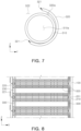
- FIG. 10 illustrates a cooling line 310 according to another exemplary embodiment of the present disclosure.
- the cooling line 310 may be used alone without a fixing line 320 (in FIG. 5 ), and the cooling line 310 may be directly seated in the recess portion 212 (in FIG. 5 ) of the sub-module case 210 (in FIG. 5 ) to face the vent hole 211 (in FIG. 5 ).
- the cooling line 310 may accommodate a coolant therein, and may be formed of a material including a third material on the outer periphery thereof in at least a partial area facing the vent hole 211 (in FIG. 5 ) and a material including a fourth material in the other area excluding the area formed of the third material.
- the fourth material may have a higher phase change temperature than the third material.
- the third material may be rubber or thermoplastic plastic, and the fourth material may be metal.
- the fourth material may be metal. According to this exemplary embodiment, in a case in which high-temperature substances are discharged from the vent hole 211 (in FIG. 5 ), only the portion formed of the third material in the cooling line is melted, and the coolant present inside the cooling line is discharged to the outside of the cooling line through the portion that had been formed of the third material before being melted.
- the third material may be polyethylene (PE) or polypropylene (PP), and the fourth material may include iron or aluminum.
- the cooling line 310 may include a plurality of discharge holes 312, and the discharge holes 312 may be provided at a position facing the vent hole 211 (in FIG. 5 ).
- Opening members 311 may be inserted and fixed into the discharge holes 312, respectively.
- the cooling line 310 may be formed of the fourth material, and the opening member 311 may be formed of the third material.
- the opening member 311 closes the discharge hole 312 in a normal state, but is melted by high-temperature substances discharged from the vent hole 211 (in FIG. 5 ) to open the discharge hole 312.
- the coolant present inside the cooling line 310 is discharged to the outside of the cooling line 310 through the discharge hole 312, and the coolant flows into the vent hole 211 (in FIG. 5 ) to extinguish flames or an explosion.
- the cooling line 310 may be used alone without a fixing line 320 (in FIG. 5 ), making it possible to reduce a weight of the battery rack.
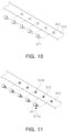
- FIG. 11 illustrates a cooling line 310 according to another exemplary embodiment of the present disclosure.
- a screw thread 311a may be formed on an outer periphery of an opening member 311, and a screw groove 312a corresponding to the screw thread 311a may be formed in a discharge hole 312 of the cooling line 310.
- the opening member 311 may be coupled to the cooling line 310.
- the cooling line 310 and the opening member 311 can be coupled to each other more firmly.
- FIG. 12 illustrates a cooling line 310 according to another exemplary embodiment of the present disclosure.
- an opening member 311 coupled to the cooling line 310 may have a rectangular shape.
- the present disclosure is not limited thereto, and the shape of the opening member 311 may be circular or a polygonal.
- FIG. 13 is a partially enlarged perspective view of a battery rack according to another exemplary embodiment of the present disclosure.
- a plurality of notches 214 may be provided in the outer periphery of the sub-module case 210.
- the notches 214 may be provided in the outer periphery of the sub-module case 210 to be connected to the vent hole 211.
- the plurality of notches 214 may be provided in the outer periphery of the sub-module case 210 to be connected to one vent hole 211.
- the plurality of notches 214 may be disposed below the cooling line 310 and the fixing line 320 in the Z-axis direction, and may be provided as consecutive grooves in the Y-axis direction.
- the coolant present inside the cooling line flows into the vent hole 211, or the coolant that fails to flow in the vent hole 211 may fall into the notches 214 present below the cooling line 310 due to gravity.
- the coolant present in the notches 214 is guided to the vent hole 211 by the notches 214. Therefore, the coolant can be supplied to the vent hole 211 more quickly, and flames or an explosion can be quickly extinguished, such that the fire or the explosion is quickly prevented from propagating to other areas.
- this exemplary embodiment in a case in which flames or an explosion occurs in one area, it is possible to prevent the fire or the explosion from spreading to the entire battery rack.
- the notches 214 may be provided in the sub-module case 210 to be inclined toward the vent hole 211. According to this exemplary embodiment, the coolant present in the notches 214 can be supplied into the vent hole 211 in a larger amount, and the coolant present in the notches 214 can be quickly supplied into the vent hole 211.
- FIG. 14 is a partial side view of a battery rack according to another exemplary embodiment of the present disclosure.
- the battery rack may further include a drainage unit 400 disposed below the cooling unit 300 (in FIG. 1 ) in the housing 100 and collecting the coolant falling to a lower side of the housing 100.
- the drainage unit 400 may include a drain plate 410 disposed on the lower side of the housing 100 and allowing the coolant to fall thereonto, and a drain pipe 420 connected to the drain plate 410 and discharging the coolant to the outside of the housing 100.
- the drain plate 410 may be provided to be inclined in the X-axis direction on the bottom surface of the housing 100.
- the drain plate 410 may be inclined to have a lowest height on the Z-axis at a point where the drain plate 410 is connected to the drain pipe 420. According to this exemplary embodiment, the coolant present on the drain plate 410 can be quickly supplied into the drain pipe 420.
- a separate pump (not shown) or the like may be connected to the drain pipe 420 to suck the coolant.
- the drain pipe 420 may be provided with a filter (not shown) or the like to filter out foreign substances present in the coolant, and supply the coolant from which the foreign substances are filtered out to the cooling line 310 again.
- the present disclosure is not limited thereto, and the separate pump and the filter may be appropriately selected and applied according to environments where the battery rack is used, requirements for the battery rack, etc.
Landscapes
- Chemical & Material Sciences (AREA)
- Chemical Kinetics & Catalysis (AREA)
- Electrochemistry (AREA)
- General Chemical & Material Sciences (AREA)
- Engineering & Computer Science (AREA)
- Manufacturing & Machinery (AREA)
- Secondary Cells (AREA)
- Battery Mounting, Suspending (AREA)
Abstract
Description
- This application claims benefit of priority to
Korean Patent Application No. 10-2021-0099001 filed on July 28, 2021 - The present disclosure relates to a battery rack.
- Secondary batteries, which are capable of charging and discharging electricity, are applicable to a wide range of devices from portable electronic devices having a relatively small size to vehicles and power storage devices having a medium or large size.
- Such a secondary battery may be used in the form of a secondary battery cell. In the secondary battery cell, a stack including a positive electrode, a negative electrode, and a separator is disposed with an electrolyte filled inside an exterior material.
- A plurality of secondary battery cells may be collected and electrically connected to each other to form a module or a pack. Also, a plurality of modules or packs may be collected and electrically connected to each other to form a battery rack. In addition, a plurality of battery racks may be electrically connected to each other to form an energy storage system (ESS).
- Since a large number of secondary battery cells are densely formed in such an energy storage system, if flames or an explosion occurs in any one of the secondary battery cells, the fire or the explosion may easily propagate or be transferred to an adjacent secondary battery cell. In addition, since a high voltage is applied to the energy storage system, if flames or an explosion occurs in the energy storage system, this may cause significant damage.
- Thus, it is a very important issue to prevent or suppress flames or an explosion in a secondary battery cell, which is a minimum unit constituting the energy storage system, and to prevent or suppress the expansion of flames or an explosion from a secondary battery cell where the fire or the explosion has first occurred to other secondary battery cells.
- (Patent Document 1)
KR 10-2010-0059505 A (June 4, 2010 - An aspect of the present disclosure may provide a battery rack capable of suppressing or preventing a battery cell from being overheated or ignited, and delaying or preventing propagation from an area in which ignition starts to other areas.
- Another aspect of the present disclosure may provide a battery rack capable of delaying or suppressing flames or an explosion therein.
- According to an aspect of the present disclosure, a battery rack may include: a housing; a module unit provided in the housing, including a plurality of battery cells, and having at least one vent hole; and a cooling unit provided to face the vent hole in the housing, and including a cooling line in which a coolant is provided, wherein the cooling line is provided so that at least a portion of an outer periphery thereof is melted by heat generated from the module unit to supply the coolant toward the vent hole.
- The cooling unit may further include a fixing line accommodating the cooling line therein, and formed of a material having a different phase change temperature from a material of the outer periphery of the cooling line.
- The fixing line may include an open portion is formed by spacing ends of the fixing line apart from each other in a cross section of the fixing line in a thickness direction, and a hollow portion, and the cooling line may be accommodated in the fixing line to directly face the vent hole in the open portion, while being present in the open portion and the hollow portion.
- The cooling line may include a first material having a first phase change temperature on the outer periphery thereof, the fixing line may include a second material having a second phase change temperature on the outer periphery thereof, and the first phase change temperature may be lower than the second phase change temperature.
- The first material may be rubber or thermoplastic plastic, and the second material may be metal.
- The cooling line may be accommodated in the fixing line to directly face each of the at least one vent hole, and the fixing line may surround at least 50% of the outer periphery of the cooling line.
- The module unit may be accommodating at least one of the battery cells, and may be formed by stacking a plurality of sub-module cases formed the vent hole, and the cooling line may be formed of a plurality of materials having different phase change temperatures.
- The cooling line may include a third material on the outer periphery thereof in an area facing the vent hole, and a fourth material having a higher phase change temperature than the third material in the other area excluding the area formed of the third material.
- The cooling line may include an opening member being present in the outer periphery thereof and formed of a material including the third material, and provided to be separated from the area formed of the fourth material.
- The cooling line may include a plurality of discharge holes are provided to each face a corresponding one of the at least one vent hole, and a plurality of opening members may be inserted into the discharge holes, respectively.
- The third material may be rubber or thermoplastic plastic, and the fourth material may be metal.
- The sub-module case may include at least one notch provided in communication with the vent hole and guiding the coolant toward the vent hole.
- The cooling unit may further include a fixing cover connected to the module unit or the housing to fix the cooling line.
- The battery rack may further include a drainage unit disposed below the cooling unit in the housing, and provided to collect falling coolant.
- The drainage unit may include: a drain plate disposed to be inclined on a lower side of the housing, and allowing the coolant to fall thereonto; and a drain pipe connected to the drain plate, and discharging the coolant to the outside of the housing.
- The above and other aspects, features, and advantages of the present disclosure will be more clearly understood from the following detailed description taken in conjunction with the accompanying drawings, in which:
-
FIG. 1 is a partially exploded perspective view of a battery rack according to an exemplary embodiment of the present disclosure; -
FIG. 2 is a partially enlarged view of a cross section of the battery rack according to an exemplary embodiment of the present disclosure when cut in a side surface direction thereof; -
FIG. 3 is a partial front view of the battery rack according to an exemplary embodiment of the present disclosure; -
FIG. 4 is a perspective view of a module unit according to an exemplary embodiment of the present disclosure; -
FIG. 5 is a partially enlarged view of a module unit and a cooling unit according to an exemplary embodiment of the present disclosure; -
FIG. 6 is a front view of a sub-module case and a cooling unit; -
FIG. 7 is a front view of a fixing line and a cooling line according to an exemplary embodiment of the present disclosure; -
FIG. 8 is a partially enlarged view of a cross section of a battery rack according to another exemplary embodiment of the present disclosure when cut in a side surface direction thereof; -
FIG. 9 is a partial front view of a state in which a fixing cover is fastened to a sub-module case; -
FIG. 10 is a perspective view of a cooling line according to another exemplary embodiment of the present disclosure; -
FIG. 11 is a perspective view of a cooling line according to another exemplary embodiment of the present disclosure; -
FIG. 12 is a perspective view of a cooling line according to another exemplary embodiment of the present disclosure; -
FIG. 13 is a partially enlarged perspective view of a battery rack according to another exemplary embodiment of the present disclosure; and -
FIG. 14 is a partial side view of a battery rack according to another exemplary embodiment of the present disclosure. - In order to facilitate the understanding of the description of exemplary embodiments of the present disclosure, elements denoted by the same reference numerals in the accompanying drawings are the same elements, and among elements performing the same function in the respective exemplary embodiments, relevant elements are denoted by the same or similar reference numerals.
- Further, in order to clarify the gist of the present disclosure, the description of elements and techniques well known in the related art will be omitted, and the present disclosure will hereinafter be described in detail with reference to the accompanying drawings.
- It is to be understood, however, that the spirit and the scope of the present disclosure are not limited to the exemplary embodiments presented herein, but other forms may be suggested by those skilled in the art while specific components are added, changed, or deleted without departing from the spirit and the scope of the present disclosure.
- In accompanying drawings, an X-axis refers to a direction in which battery cells provided in a battery rack are stacked, a Y-axis refers to a width direction of the battery rack, and a Z-axis refers to a length direction of the battery rack.
-
FIG. 1 illustrates a partially exploded perspective view of abattery rack 1000 according to an exemplary embodiment of the present disclosure. - As shown in
FIG. 1 , thebattery rack 1000 according to an exemplary embodiment of the present disclosure may include ahousing 100 forming the exterior of the battery rack, amodule unit 200 formed by a plurality of battery cells provided in thehousing 100, and acooling unit 300 provided to face themodule unit 200 in thehousing 100 and accommodating a coolant therein. - In an exemplary embodiment of the present disclosure, the
module unit 200 may be formed by stacking the plurality of battery cells in the X-axis direction. - In addition, a plurality of
module units 200 may be provided and stacked in the Z-axis direction in thehousing 100. - In addition, the plurality of
module units 200 may be spaced apart from one another by a predetermined distance in the Z-axis direction. A space formed by spacing themodule units 200 apart from one another in the Z-axis direction may serve as a passage for cooling themodule units 200 using an external fluid, and the external fluid may be, for example, air. - In an exemplary embodiment of the present disclosure, the
housing 100 may includeside panels 110 fastened to both sides thereof and arear panel 120 fastened to a rear side thereof. Theside panels 110 and therear panel 120 may constitute thehousing 100, while each being spaced apart from themodule units 200 by a predetermined distance. - A space formed by spacing the
rear panel 120 apart from themodule units 200 may serve as a flow path through which the external fluid moves to cool themodule units 200. - In an exemplary embodiment of the present disclosure, a separate cooling fan (not shown), which is not illustrated in the drawings, may be installed in the
housing 100. The external fluid may be introduced into the space (not shown) between themodule units 200 and the space (not shown) between themodule units 200 and therear panel 120 by the cooling fan (not shown), and the external fluid having passed through the space (not shown) between themodule units 200 and the space between themodule units 200 and therear panel 120 may be discharged to the outside of thehousing 100. - The external fluid may be air, but the present disclosure is not limited thereto. The type of external fluid may be appropriately selected and applied according to environments where the battery rack is used, requirements for the battery rack, etc.
- The
cooling unit 300 may be disposed in the space formed by spacing themodule units 200 apart from theside panel 110. Thecooling unit 300 may extend in at least one of the X-axis direction and the Z-axis direction to face all of the plurality ofmodule units 200. - In an exemplary embodiment of the present disclosure, the
cooling unit 300 may include a pipe containing a coolant therein, and at least a portion of an outer periphery of the pipe may be disposed to face themodule units 200. - The outer periphery of the pipe may be formed of a material that is melted by heat generated from the
module unit 200. According to this exemplary embodiment, the outer periphery of the pipe can be melted by heat generated from themodule unit 200, and the coolant can be discharged to the outside of the pipe. The coolant discharged to the outside of the pipe may be used to cool themodule unit 200. - In an exemplary embodiment of the present disclosure, the type of coolant may be water, but the present disclosure is also not limited thereto. The type of coolant may be appropriately selected and applied according to environments where the battery rack is used, requirements for the battery rack, etc.
-
FIG. 2 is a partially enlarged view of a cross section of the battery rack according to an exemplary embodiment of the present disclosure when cut in a side surface direction thereof. - As shown in
FIG. 2 , the module unit 200 (inFIG. 1 ) may include a plurality ofsub-module cases 210 stacked in the X-axis direction, at least onepad member 201 disposed between thesub-module cases 210, aframe 230 surrounding side surfaces of thesub-module cases 210 and thepad member 201, afront panel 220 surrounding a front surface of thesub-module case 210 or thepad member 201 and exposed to the outside of thehousing 100, and aconnection member 221 disposed on thefront panel 220 and electrically connecting the plurality of module units 200 (inFIG. 1 ) to each other. - A bus bar (not shown) connected to leads (not shown) of the battery cells provided in the
sub-module cases 210 may be provided on an inner surface of theframe 230. The bus bar (not shown) may be electrically connected to theconnection member 221. - The
pad member 201 may serve to cool thesub-module cases 210 or absorb expansion of thesub-module cases 210 according to expansion of the battery cells (not shown). - Meanwhile, the cooling unit 300 (in
FIG. 1 ) may include afixing line 320 extending in the X-axis direction and in the Z-axis direction to face thesub-module cases 210. The fixingline 320 may be a pipe as described above. And the line mentioned in the present specification may refer to a pipe. -
FIG. 3 is a partial front view of thebattery rack 1000 according to an exemplary embodiment of the present disclosure. - As shown in
FIG. 3 , the plurality ofmodule units 200 may be spaced apart from one another by a predetermined distance in the Z-axis direction, and a space formed by spacing the plurality ofmodule units 200 apart from one another may serve as acooling passage 202. Thecooling passage 202 may be a flow path of an external fluid as described above, and the external fluid may be air. -
Front panels 220 may be provided on respective front sides of themodule units 200, andconnection members 221 may be provided on the respectivefront panels 220. Theconnection members 221 may be electrically connected to acontrol unit 101 disposed at an upper portion of thehousing 100. - A fixing
line 320 may be disposed on one side of themodule unit 200, and another fixingline 320 may also be disposed on the other side of themodule unit 200. -
FIG. 4 is a perspective view of themodule unit 200 according to an exemplary embodiment of the present disclosure. - As shown in
FIG. 4 , themodule unit 200 may be formed by stacking a plurality ofsub-module cases 210. At least one battery cell (not shown) may be accommodated in thesub-module case 210. - The
sub-module case 210 may have a space (not shown) through which a lead (not shown) of the battery cell (not shown) is drawn out. Thesub-module case 210 may include arecess portion 212 concavely formed on an outer periphery thereof in a +Y direction or in a -Y direction. - The
recess portion 212 may be formed on each of both sides of thesub-module case 210, and a plurality ofrecess portions 212 may be formed on each side of thesub-module case 210 in a +Z direction or in a -Z direction. - A
vent hole 211 may be disposed in therecess portion 212. Thevent hole 211, which is a through-hole formed in thesub-module case 210 so that an internal space of thesub-module case 210 communicates with the outside, may serve as a passage through which gas inside thesub-module case 210 is discharged to the outside of thesub-module case 210. - The
vent hole 211 may be covered with a cover member (not shown) in a normal state. The cover member (not shown) may be attached to thesub-module case 210 by an adhesive or the like. If a battery cell fires or explodes, the cover member (not shown) may be detached from thesub-module case 210 by virtue of the fluid discharged from the inside of the sub-module case, particles that may be generated when the battery cell catches fire or explodes, and the like, thereby opening thevent hole 211. However, thevent hole 211 may be open, rather than being covered with the cover member (not shown). - A
front panel 220 may be disposed in front of the outermostsub-module case 210 among the plurality of thesub-module cases 210 constituting themodule unit 200, and frames 230 may extend from both sides of thefront panel 220, respectively. Theframes 230 may easily fix the plurality of thesub-module cases 210 by surrounding side surfaces of the plurality of thesub-module cases 210 stacked. If necessary, theframes 230 may surround the rear of thesub-module case 210, but the present disclosure is not limited thereto. -
FIG. 5 is a partially enlarged view of the module unit 200 (inFIG. 1 ) and the cooling unit 300 (inFIG. 1 ) according to an exemplary embodiment of the present disclosure. - As shown in
FIG. 5 , the fixingline 320 of the cooling unit may be disposed to face thevent hole 211 of thesub-module case 210 in the housing 100 (inFIG. 1 ). - The fixing
line 320 may be inserted into therecess portion 212 of thesub-module case 210, and the fixingline 320 may be disposed to face each of the vent holes 211 of the plurality ofsub-module cases 210 in thehousing 100. - A
cooling line 310 may be accommodated inside the fixingline 320, and thecooling line 310 may also be disposed inside the fixingline 320 to face each of the vent holes 211 of the plurality ofsub-module cases 210. - The
cooling line 310 may be provided so that the coolant is present inside thecooling line 310 in a normal state, but the coolant is discharged to the outside of thecooling line 310 when at least a portion of thecooling line 310 is melted by heat transferred from substances discharged through thevent hole 211 in a case in which a battery cell (not shown) fires or explodes. - At this time, since the cover member (not shown), which closes the
vent hole 211 in the normal state, is detached from thesub-module case 210 by virtue of the substances ejected through thevent hole 211, thevent hole 211 becomes opened. However, in a case in which the cover member (not shown) is provided in a hinged manner to open or close thevent hole 211 by moving around thesub-module case 210, the cover member (not shown) may be moved from thesub-module case 210 due to the pressure of the fluid or particles discharged from thevent hole 211, and thevent hole 211 may become opened. - When the
vent hole 211 becomes opened as described above, the coolant present inside thecooling line 310 may flow into thesub-module case 210 through thevent hole 211, and the battery cell (not shown) present inside thesub-module case 210 may be cooled by the coolant. - According to this exemplary embodiment, the coolant can be supplied through the
vent hole 211 at a position closest to an overheated or ignited battery cell, thereby reducing an amount of time in which the coolant reaches the battery cell requiring the coolant. As a result, it is possible to quickly lower a temperature of the overheated or ignited battery cell, and it is also possible to delay or prevent the propagation of flames or an explosion to other battery cells or other areas of the battery rack. -
FIG. 6 is a front view of thesub-module case 210 and the cooling unit 300 (inFIG. 1 ) disposed on thesub-module case 210. - As shown in
FIG. 6 , at least one battery cell (not shown) may be accommodated in theinternal space 213 of thesub-module case 210. - The fixing
line 320 may fix thecooling line 310 in a state where at least a portion of thecooling line 310 is exposed so that at least a portion of thecooling line 310 directly faces thevent hole 211. The fixingline 320 may have a shape to surround at least a portion of thecooling line 310. - A coolant is accommodated in the
cooling line 310. Both ends (not shown) of thecooling line 310 may be connected to a separate pump (not shown) or the like such that the coolant accommodated in thecooling line 310 circulates along thecooling line 310, but the present disclosure is not limited thereto. - An outer periphery of the fixing
line 320 may include a different material from an outer periphery of thecooling line 310, and the material included the outer periphery of the fixingline 320 may have a higher phase change temperature than the material included the outer periphery of thecooling line 310. In this case, the phase change temperature may be a melting point. - In an exemplary embodiment of the present disclosure, the
cooling line 310 may include a first material having a first phase change temperature, and the fixingline 320 may include a second material having a second phase change temperature. - In an exemplary embodiment of the present disclosure, the first phase change temperature may be a value in the range of 140°C or more and 220°C or less. In addition, the second phase change temperature may be a value in the range of more than 220°C and 1540°C or less.
- According to this exemplary embodiment, it is possible to prevent the
fixing line 320 from being melted even though the outer periphery of thecooling line 310 is melted by high-temperature substances discharged through thevent hole 211 in a case in which flames or an explosion occurs. - If a battery cell (not shown) is overheated or ignited, high-temperature substances may be discharged to the outside of the
sub-module case 210 through at least onevent hole 211 located close to the overheated or ignited battery cell (not shown). - Then, at least a partial portion of the outer periphery of the
cooling line 310 may be melted by heat, and accordingly, the coolant present inside thecooling line 310 may be discharged to the outside of thecooling line 310. - In an exemplary embodiment of the present disclosure, the phase change temperature of the
cooling line 310 may be a value in the range of 140°C or more and 220°C or less. In this case, the phase change temperature of the fixingline 320 may be a value in the range of more than 220°C and 1540°C or less. - In an exemplary embodiment of the present disclosure, the first material may be rubber or thermoplastic plastic, and the second material may be metal.
- When the first material is rubber or thermoplastic plastic, the first material has elasticity. Therefore, the
cooling line 310 may contract when thecooling line 310 is being inserted into the fixingline 320 through an open area thereof, and thecooling line 310 may be recovered to its original elasticity when the insertion of thecooling line 310 into the fixingline 320 is completed. According to this exemplary embodiment, it is possible to improve efficiency and convenience in assembling the fixingline 320 and thecooling line 310 together. - Also, in an exemplary embodiment of the present disclosure, the first material may be polyethylene (PE) or polypropylene (PP), and the second material may include iron or aluminum. In a case in which the second material is iron, the second material may have a phase change temperature of about 1538°C, making it possible to improve the durability of the fixing
line 320. On the other hand, in a case in which the second material is aluminum, the second material may have a phase change temperature of about 661°C, making it possible to reduce a weight of the battery rack because aluminum is lighter than iron. However, the present disclosure is not limited thereto, and the types of materials may be appropriately selected and applied according to environments in which the battery rack is used and requirements for the battery rack. Alternatively, the second material may be an alloy to improve corrosion resistance, or a corrosion resistance coating may be applied onto an outer surface of the fixing line. - In addition to the above-described second material, the fixing
line 320 may include a material capable of maintaining its shape even if flames or an explosion occurs or even in a relatively high temperature environment. The fixingline 320 including a material capable of maintaining its shape even in a high temperature environment or even in an environment where flames or an explosion has occurred makes it possible to smoothly maintain the flow of the coolant discharged from thecooling line 310 even in a high temperature, fire, or explosion environment. -
FIG. 7 illustrates a front view of the fixingline 320 and thecooling line 310 according to an exemplary embodiment of the present disclosure. - As shown in
FIG. 7 , the fixingline 320 includes a hollow inside, and the hollow may form ahollow portion 320a. Opposite ends 321 of the fixingline 320 may be spaced apart from each other, and anopen portion 322 may be formed between the opposite ends 321. - The
cooling line 310 may also include a hollow inside, and the hollow may form anotherhollow portion 310a. Thecooling line 310 may be inserted into the fixingline 320 through theopen portion 322 to be placed in thehollow portion 320a of the fixingline 320. - As described above, the
cooling line 310 may contract due to elasticity thereof while being inserted through the open portion, and may be recovered to original elasticity thereof when the insertion of thecooling line 310 into thehollow portion 320a of the fixingline 320 is completed. - At least a portion of the outer periphery of the
cooling line 310 having been inserted into thehollow portion 320a of the fixingline 320 may be present in theopen portion 322, and at least a portion of the outer periphery of thecooling line 310 exposed through theopen portion 322 may directly face the vent hole 211 (inFIG. 6 ). - According to this exemplary embodiment, heat discharged from the vent hole 211 (in
FIG. 6 ) can be quickly and easily transferred to thecooling line 310, and the coolant present in thehollow portion 310a of thecooling line 310 can be quickly discharged to the outside of thecooling line 310. - In an exemplary embodiment of the present disclosure, the fixing
line 320 may surround at least 50% of the outer periphery of thecooling line 310. According to this exemplary embodiment, while preventing thecooling line 310 from escaping away from the fixingline 320, the coolant inside thecooling line 310 can be easily discharged to the outside of thecooling line 310. -
FIG. 8 is a partially enlarged view of a cross section of a battery rack according to another exemplary embodiment of the present disclosure when cut in a side surface direction thereof. - As shown in
FIG. 8 , the cooling unit 300 (inFIG. 1 ) of the battery rack according to another exemplary embodiment of the present disclosure may further include a fixingcover 330 connected to the module unit 200 (inFIG. 1 ) or the housing 100 (inFIG. 1 ) to fix the cooling line 310 (inFIG. 5 ). - The fixing
cover 330 may fix the cooling line 310 (inFIG. 5 ) by fixing the fixingline 320 in which the cooling line 310 (inFIG. 5 ) is accommodated, or fix the cooling line 310 (inFIG. 5 ) by directly contacting the cooling line 310 (inFIG. 5 ). - In the exemplary embodiment illustrated in
FIG. 8 , the fixingcover 330 fixes thecooling line 310 by fixing the fixingline 320. - A plurality of fixing covers 330 may be provided and applied to a section in which the
fixing line 320 extends in a direction parallel to the Z-axis. -
FIG. 9 is a partial front view of a state in which the fixingcover 330 illustrated inFIG. 8 is fastened to thesub-module case 210. - As shown in
FIG. 9 , oneend 331 of the fixingcover 330 may be bent to contact the outer periphery of thesub-module case 210, and the other end of the fixingcover 330 may also be bent to contact the outer periphery of thesub-module case 210. The fixingcover 330 may be fixed to thesub-module case 210 by virtue of the both ends 331 of the fixingcover 330 pressing thesub-module case 210. - To this end, the fixing
cover 330 may be formed of an elastic material, but the present disclosure is also not limited thereto. In a case in which the fixingcover 330 is formed of a non-elastic material, both ends 331 of the fixingcover 330 may be bonded to thesub-module case 210 by an adhesive or the like. - The fixing
cover 330 may be fixed to thesub-module case 210 so that an inner surface thereof covers at least one of thecooling line 310 and the fixingline 320, and may have anavoidance groove 332 in the inner surface thereof to accommodate the frame fixing thesub-module case 210 therein. - The fixing
cover 330 may serve to prevent at least one of thecooling line 310 and the fixingline 320 from escaping to the outside of thesub-module case 210. In an exemplary embodiment of the present disclosure, the outer periphery of at least one of thecooling line 310 and the fixingline 320 may contact thesub-module case 210 in therecess portion 212 of thesub-module case 210, and a lower portion thereof may be supported by thesub-module case 210. - An outer surface of the fixing
cover 330 may contact an inner surface of the housing 100 (inFIG. 1 ), but the present disclosure is not limited thereto, and may be appropriately selected and applied according to environments where the battery rack is used and requirements for the battery rack. -
FIG. 10 illustrates acooling line 310 according to another exemplary embodiment of the present disclosure. In this case, thecooling line 310 may be used alone without a fixing line 320 (inFIG. 5 ), and thecooling line 310 may be directly seated in the recess portion 212 (inFIG. 5 ) of the sub-module case 210 (inFIG. 5 ) to face the vent hole 211 (inFIG. 5 ). - The
cooling line 310 may accommodate a coolant therein, and may be formed of a material including a third material on the outer periphery thereof in at least a partial area facing the vent hole 211 (inFIG. 5 ) and a material including a fourth material in the other area excluding the area formed of the third material. - In an exemplary embodiment of the present disclosure, the fourth material may have a higher phase change temperature than the third material. The third material may be rubber or thermoplastic plastic, and the fourth material may be metal. According to this exemplary embodiment, in a case in which high-temperature substances are discharged from the vent hole 211 (in
FIG. 5 ), only the portion formed of the third material in the cooling line is melted, and the coolant present inside the cooling line is discharged to the outside of the cooling line through the portion that had been formed of the third material before being melted. - In an exemplary embodiment of the present disclosure, the third material may be polyethylene (PE) or polypropylene (PP), and the fourth material may include iron or aluminum.
- In addition, in an exemplary embodiment of the present disclosure, the
cooling line 310 may include a plurality of discharge holes 312, and the discharge holes 312 may be provided at a position facing the vent hole 211 (inFIG. 5 ). - Opening
members 311 may be inserted and fixed into the discharge holes 312, respectively. In an exemplary embodiment of the present disclosure, thecooling line 310 may be formed of the fourth material, and the openingmember 311 may be formed of the third material. - The opening
member 311 closes thedischarge hole 312 in a normal state, but is melted by high-temperature substances discharged from the vent hole 211 (inFIG. 5 ) to open thedischarge hole 312. - Then, the coolant present inside the
cooling line 310 is discharged to the outside of thecooling line 310 through thedischarge hole 312, and the coolant flows into the vent hole 211 (inFIG. 5 ) to extinguish flames or an explosion. - In this case, the
cooling line 310 may be used alone without a fixing line 320 (inFIG. 5 ), making it possible to reduce a weight of the battery rack. -
FIG. 11 illustrates acooling line 310 according to another exemplary embodiment of the present disclosure. - As shown in
FIG. 11 , ascrew thread 311a may be formed on an outer periphery of an openingmember 311, and ascrew groove 312a corresponding to thescrew thread 311a may be formed in adischarge hole 312 of thecooling line 310. By coupling the screw thread into the screw groove, the openingmember 311 may be coupled to thecooling line 310. According to this exemplary embodiment, thecooling line 310 and the openingmember 311 can be coupled to each other more firmly. - Meanwhile,
FIG. 12 illustrates acooling line 310 according to another exemplary embodiment of the present disclosure. As shown inFIG. 12 , an openingmember 311 coupled to thecooling line 310 may have a rectangular shape. However, the present disclosure is not limited thereto, and the shape of the openingmember 311 may be circular or a polygonal. -
FIG. 13 is a partially enlarged perspective view of a battery rack according to another exemplary embodiment of the present disclosure. - As shown in
FIG. 13 , in another exemplary embodiment of the present disclosure, a plurality ofnotches 214 may be provided in the outer periphery of thesub-module case 210. Thenotches 214 may be provided in the outer periphery of thesub-module case 210 to be connected to thevent hole 211. - The plurality of
notches 214 may be provided in the outer periphery of thesub-module case 210 to be connected to onevent hole 211. The plurality ofnotches 214 may be disposed below thecooling line 310 and the fixingline 320 in the Z-axis direction, and may be provided as consecutive grooves in the Y-axis direction. - When the
cooling line 310 is melted, the coolant present inside the cooling line flows into thevent hole 211, or the coolant that fails to flow in thevent hole 211 may fall into thenotches 214 present below thecooling line 310 due to gravity. - Since the
notches 214 are provided in thesub-module case 210 to be connected to thevent hole 211, the coolant present in thenotches 214 is guided to thevent hole 211 by thenotches 214. Therefore, the coolant can be supplied to thevent hole 211 more quickly, and flames or an explosion can be quickly extinguished, such that the fire or the explosion is quickly prevented from propagating to other areas. According to this exemplary embodiment, in a case in which flames or an explosion occurs in one area, it is possible to prevent the fire or the explosion from spreading to the entire battery rack. - In an exemplary embodiment of the present disclosure, the
notches 214 may be provided in thesub-module case 210 to be inclined toward thevent hole 211. According to this exemplary embodiment, the coolant present in thenotches 214 can be supplied into thevent hole 211 in a larger amount, and the coolant present in thenotches 214 can be quickly supplied into thevent hole 211. -
FIG. 14 is a partial side view of a battery rack according to another exemplary embodiment of the present disclosure. - As shown in
FIG. 14 , the battery rack according to another exemplary embodiment of the present disclosure may further include adrainage unit 400 disposed below the cooling unit 300 (inFIG. 1 ) in thehousing 100 and collecting the coolant falling to a lower side of thehousing 100. - The
drainage unit 400 may include adrain plate 410 disposed on the lower side of thehousing 100 and allowing the coolant to fall thereonto, and adrain pipe 420 connected to thedrain plate 410 and discharging the coolant to the outside of thehousing 100. - The
drain plate 410 may be provided to be inclined in the X-axis direction on the bottom surface of thehousing 100. In an exemplary embodiment of the present disclosure, thedrain plate 410 may be inclined to have a lowest height on the Z-axis at a point where thedrain plate 410 is connected to thedrain pipe 420. According to this exemplary embodiment, the coolant present on thedrain plate 410 can be quickly supplied into thedrain pipe 420. - A separate pump (not shown) or the like may be connected to the
drain pipe 420 to suck the coolant. In addition, thedrain pipe 420 may be provided with a filter (not shown) or the like to filter out foreign substances present in the coolant, and supply the coolant from which the foreign substances are filtered out to thecooling line 310 again. However, the present disclosure is not limited thereto, and the separate pump and the filter may be appropriately selected and applied according to environments where the battery rack is used, requirements for the battery rack, etc. - As set forth above, according to exemplary embodiments of the present disclosure, it is possible to suppress or prevent a battery cell from being overheated or ignited, and it is also possible to delay or prevent propagation from an area in which ignition starts to other areas.
- In addition, according to exemplary embodiments of the present disclosure, it is possible to delay or suppress flames or an explosion in the battery rack.
- While exemplary embodiments have been shown and described above, it will be apparent to those skilled in the art that modifications and variations could be made without departing from the scope of the present invention as defined by the appended claims.
Claims (15)
- A battery rack comprising:a housing;a module unit provided in the housing, including a plurality of battery cells, and having at least one vent hole; anda cooling unit provided to face the vent hole in the housing, and including a cooling line in which a coolant is provided,wherein the cooling line is provided so that at least a portion of an outer periphery thereof is melted by heat generated from the module unit to supply the coolant toward the vent hole.
- The battery rack of claim 1, wherein the cooling unit further includes a fixing line accommodating the cooling line therein, and formed of a material having a different phase change temperature from a material of the outer periphery of the cooling line.
- The battery rack of claim 2, wherein the fixing line includes an open portion is formed by spacing ends of the fixing line apart from each other in a cross section of the fixing line in a thickness direction, and a hollow portion, and
the cooling line is accommodated in the fixing line to directly face the vent hole in the open portion, while being present in the open portion and the hollow portion. - The battery rack of claim 3, wherein the cooling line includes a first material having a first phase change temperature on the outer periphery thereof,the fixing line includes a second material having a second phase change temperature on the outer periphery thereof, andthe first phase change temperature is lower than the second phase change temperature.
- The battery rack of claim 4, wherein the first material is rubber or thermoplastic plastic, and
the second material is metal. - The battery rack of claim 2, wherein the cooling line is accommodated in the fixing line to directly face each of the at least one vent hole, and
the fixing line surrounds at least 50% of the outer periphery of the cooling line. - The battery rack of claim 1, wherein the module unit is accommodating at least one of the battery cells, and formed by stacking a plurality of sub-module cases formed the vent hole, and
wherein the cooling line is formed of a plurality of materials having different phase change temperatures. - The battery rack of claim 7, wherein the cooling line includes a third material on the outer periphery thereof in an area facing the vent hole, and a fourth material having a higher phase change temperature than the third material in the other area excluding the area formed of the third material.
- The battery rack of claim 10, wherein the cooling line includes an opening member being present in the outer periphery thereof and formed of a material including the third material, and provided to be separated from the area formed of the fourth material.
- The battery rack of claim 9, wherein the cooling line includes a plurality of discharge holes are provided to each face a corresponding one of the at least one vent hole, and
a plurality of opening members are inserted into the discharge holes, respectively. - The battery rack of claim 10, wherein the third material is rubber or thermoplastic plastic, and
the fourth material is metal. - The battery rack of claim 7, wherein the sub-module case includes at least one notch provided in communication with the vent hole and guiding the coolant toward the vent hole.
- The battery rack of any one of claims 1 to 12, wherein the cooling unit further includes a fixing cover connected to the module unit or the housing to fix the cooling line.
- The battery rack of any one of claims 1 to 12, further comprising a drainage unit disposed below the cooling unit in the housing, and provided to collect falling coolant.
- The battery rack of claim 14, wherein the drainage unit includes:a drain plate disposed to be inclined on a lower side of the housing, and allowing the coolant to fall thereonto; anda drain pipe connected to the drain plate, and discharging the coolant to the outside of the housing.
Applications Claiming Priority (1)
| Application Number | Priority Date | Filing Date | Title |
|---|---|---|---|
| KR1020210099001A KR102956952B1 (en) | 2021-07-28 | Battery Rack |
Publications (2)
| Publication Number | Publication Date |
|---|---|
| EP4125147A2 true EP4125147A2 (en) | 2023-02-01 |
| EP4125147A3 EP4125147A3 (en) | 2023-07-12 |
Family
ID=82492851
Family Applications (1)
| Application Number | Title | Priority Date | Filing Date |
|---|---|---|---|
| EP22181899.0A Pending EP4125147A3 (en) | 2021-07-28 | 2022-06-29 | Battery rack |
Country Status (2)
| Country | Link |
|---|---|
| US (2) | US12444787B2 (en) |
| EP (1) | EP4125147A3 (en) |
Families Citing this family (1)
| Publication number | Priority date | Publication date | Assignee | Title |
|---|---|---|---|---|
| KR102833353B1 (en) * | 2020-10-19 | 2025-07-10 | 주식회사 엘지에너지솔루션 | Battery Rack, Energy Storage System, and Data Storage Device |
Family Cites Families (11)
| Publication number | Priority date | Publication date | Assignee | Title |
|---|---|---|---|---|
| JP4569534B2 (en) * | 2006-07-19 | 2010-10-27 | トヨタ自動車株式会社 | Assembled battery |
| KR101059891B1 (en) | 2008-11-26 | 2011-08-29 | 킴스테크날리지 주식회사 | High power electrical energy storage device having a unit cell and the unit cell |
| US9093726B2 (en) * | 2009-09-12 | 2015-07-28 | Tesla Motors, Inc. | Active thermal runaway mitigation system for use within a battery pack |
| US20140011059A1 (en) * | 2011-03-31 | 2014-01-09 | Hiroyuki Hashimoto | Power supply device and vehicle equipped therewith |
| JP6297922B2 (en) * | 2014-05-23 | 2018-03-20 | 株式会社デンソー | Battery pack |
| US20180191038A1 (en) * | 2015-07-20 | 2018-07-05 | Microvast Power Systems Co., Ltd. | Battery pack and battery pack system |
| KR102203248B1 (en) | 2017-04-07 | 2021-01-13 | 주식회사 엘지화학 | Battery module and battery pack including the same |
| KR102258816B1 (en) * | 2017-06-27 | 2021-05-31 | 주식회사 엘지에너지솔루션 | Battery Module |
| KR102330377B1 (en) | 2018-10-12 | 2021-11-22 | 주식회사 엘지에너지솔루션 | Battery module, battery rack comprising the battery module, and energy storage system comprising the battery rack |
| KR102415558B1 (en) | 2019-02-11 | 2022-07-01 | 주식회사 엘지에너지솔루션 | An energy storage system having a structure in which a coolant can be injected into a battery module |
| CN112332013B (en) | 2019-09-26 | 2021-10-01 | 宁德时代新能源科技股份有限公司 | Battery pack, vehicle and control method for alleviating the spread of thermal runaway of battery pack |
-
2022
- 2022-06-20 US US17/844,359 patent/US12444787B2/en active Active
- 2022-06-29 EP EP22181899.0A patent/EP4125147A3/en active Pending
-
2025
- 2025-09-17 US US19/330,864 patent/US20260018705A1/en active Pending
Also Published As
| Publication number | Publication date |
|---|---|
| EP4125147A3 (en) | 2023-07-12 |
| US20230033625A1 (en) | 2023-02-02 |
| US20260018705A1 (en) | 2026-01-15 |
| US12444787B2 (en) | 2025-10-14 |
| KR20230017479A (en) | 2023-02-06 |
Similar Documents
| Publication | Publication Date | Title |
|---|---|---|
| JP7033235B2 (en) | Battery modules with cooling components, battery packs, and power storage devices | |
| CN114207921B (en) | Battery module including flame retardant sheet, battery rack and energy storage system including the battery module | |
| EP3644403B1 (en) | Battery module having gas discharge structure | |
| EP3716392B1 (en) | Battery module having improved cooling structure | |
| CN114424397B (en) | Battery pack and device including the battery pack | |
| US12438227B2 (en) | Battery pack and device including the same | |
| CN108604653A (en) | Battery pack | |
| US20260018705A1 (en) | Battery rack | |
| US20230291071A1 (en) | Battery pack | |
| EP4383415A1 (en) | Battery pack | |
| JP7453336B2 (en) | Battery module with base insulation member | |
| KR20240012290A (en) | Battery module and, battery pack and vehicle including same | |
| EP4407774B1 (en) | Battery cell unit, and battery pack and vehicle including the same | |
| KR20230095812A (en) | Battery pack with improved safety | |
| KR20230099637A (en) | Battery pack with improved safety | |
| EP4376155A1 (en) | Battery pack with improved safety | |
| KR102956952B1 (en) | Battery Rack | |
| EP4131615A1 (en) | Battery module and battery pack including same | |
| CN117999696A (en) | Battery pack with improved safety | |
| KR20230133621A (en) | Battery pack and energy storage system including the same | |
| KR20260057016A (en) | Battery Rack | |
| EP4597684A1 (en) | Battery pack with improved fire protection performance | |
| KR102960996B1 (en) | Battery module with improved fire protection performance | |
| EP4376199A1 (en) | Battery pack with improved safety | |
| KR20240097567A (en) | Battery pack suitable for water drain |
Legal Events
| Date | Code | Title | Description |
|---|---|---|---|
| PUAI | Public reference made under article 153(3) epc to a published international application that has entered the european phase |
Free format text: ORIGINAL CODE: 0009012 |
|
| STAA | Information on the status of an ep patent application or granted ep patent |
Free format text: STATUS: THE APPLICATION HAS BEEN PUBLISHED |
|
| AK | Designated contracting states |
Kind code of ref document: A2 Designated state(s): AL AT BE BG CH CY CZ DE DK EE ES FI FR GB GR HR HU IE IS IT LI LT LU LV MC MK MT NL NO PL PT RO RS SE SI SK SM TR |
|
| PUAL | Search report despatched |
Free format text: ORIGINAL CODE: 0009013 |
|
| AK | Designated contracting states |
Kind code of ref document: A3 Designated state(s): AL AT BE BG CH CY CZ DE DK EE ES FI FR GB GR HR HU IE IS IT LI LT LU LV MC MK MT NL NO PL PT RO RS SE SI SK SM TR |
|
| P01 | Opt-out of the competence of the unified patent court (upc) registered |
Effective date: 20230602 |
|
| RIC1 | Information provided on ipc code assigned before grant |
Ipc: A62C 3/16 20060101ALI20230602BHEP Ipc: H01M 50/244 20210101ALI20230602BHEP Ipc: H01M 10/6567 20140101ALI20230602BHEP Ipc: H01M 10/613 20140101AFI20230602BHEP |
|
| STAA | Information on the status of an ep patent application or granted ep patent |
Free format text: STATUS: REQUEST FOR EXAMINATION WAS MADE |
|
| 17P | Request for examination filed |
Effective date: 20231129 |
|
| RBV | Designated contracting states (corrected) |
Designated state(s): AL AT BE BG CH CY CZ DE DK EE ES FI FR GB GR HR HU IE IS IT LI LT LU LV MC MK MT NL NO PL PT RO RS SE SI SK SM TR |