EP4125140A2 - Vibration power generation device and moving object - Google Patents
Vibration power generation device and moving object Download PDFInfo
- Publication number
- EP4125140A2 EP4125140A2 EP22187202.1A EP22187202A EP4125140A2 EP 4125140 A2 EP4125140 A2 EP 4125140A2 EP 22187202 A EP22187202 A EP 22187202A EP 4125140 A2 EP4125140 A2 EP 4125140A2
- Authority
- EP
- European Patent Office
- Prior art keywords
- vibration
- power generation
- generation device
- fluid
- wall surface
- Prior art date
- Legal status (The legal status is an assumption and is not a legal conclusion. Google has not performed a legal analysis and makes no representation as to the accuracy of the status listed.)
- Granted
Links
Images






Classifications
-
- H—ELECTRICITY
- H02—GENERATION; CONVERSION OR DISTRIBUTION OF ELECTRIC POWER
- H02N—ELECTRIC MACHINES NOT OTHERWISE PROVIDED FOR
- H02N2/00—Electric machines in general using piezoelectric effect, electrostriction or magnetostriction
- H02N2/18—Electric machines in general using piezoelectric effect, electrostriction or magnetostriction producing electrical output from mechanical input, e.g. generators
- H02N2/185—Electric machines in general using piezoelectric effect, electrostriction or magnetostriction producing electrical output from mechanical input, e.g. generators using fluid streams
-
- H—ELECTRICITY
- H02—GENERATION; CONVERSION OR DISTRIBUTION OF ELECTRIC POWER
- H02N—ELECTRIC MACHINES NOT OTHERWISE PROVIDED FOR
- H02N2/00—Electric machines in general using piezoelectric effect, electrostriction or magnetostriction
- H02N2/18—Electric machines in general using piezoelectric effect, electrostriction or magnetostriction producing electrical output from mechanical input, e.g. generators
- H02N2/186—Vibration harvesters
-
- H—ELECTRICITY
- H10—SEMICONDUCTOR DEVICES; ELECTRIC SOLID-STATE DEVICES NOT OTHERWISE PROVIDED FOR
- H10N—ELECTRIC SOLID-STATE DEVICES NOT OTHERWISE PROVIDED FOR
- H10N35/00—Magnetostrictive devices
- H10N35/101—Magnetostrictive devices with mechanical input and electrical output, e.g. generators, sensors
Definitions
- the present invention relates to a vibration power generation device and a moving object.
- vibration power generation devices that generate power by electromagnetic induction or piezoelectric phenomenon using vibration have been developed.
- a vibration power generation device has been proposed in which a weight is installed at the end of a magnetostrictive rod wound with a coil, and the vibration of the weight causes the magnetostrictive rod to vibrates, and partially expand and contract, generating electricity through the reverse magnetostriction effect (for example, see International Publication WO 2011/158473 ).
- An object of the present invention to provide a vibration power generation device and a moving object having high power generation efficiency.
- said object is solved by a vibration power generation device having the features of independent claim 1. Moreover, according to the present invention said object is solved by a moving object having the features of independent claim 12. Preferred embodiments are laid down in the dependent claims.
- a vibration power generation device comprises a vibration exciting body in which vibration is caused by a flowing fluid, a vibrated body which is oscillatable and is connected to the vibration exciting body, and a power generator that generates electricity by oscillation of the vibrated body, wherein the vibration exciting body is disposed in proximity to a wall surface, and vibration is caused in the vibration exciting body by a fluid flowing along the wall surface.
- the vibration exciting body is disposed in proximity to the wall surface, which aids the vibration of the vibration exciting body, thus increasing the vibration of the vibration exciting body even outside of the flow velocity range where lock-in phenomenon is associated. That is, even if the vortex shedding frequency of the vibration exciting body does not match the natural frequency of the vibration system consisting of the vibration exciting body and the vibrated body, the vibration exciting body can be sufficiently vibrated, which can further improve the power generation efficiency.
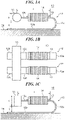
- FIGS. 1A to 1C illustrate the configuration of the vibration power generation device according to an embodiment of the present teaching.
- FIG. 1A is a side view of the vibration power generation device
- FIG. 1B is a plan view of the vibration power generation device
- FIG. 1C is a side view of a modification of the vibration power generation device.
- a vibration power generation device 10 has a vibration exciting body 11, which is a long weight, and two long plate-shaped frames 12 connected at one end to the vibration exciting body 11.
- the frames 12 are disposed parallel to each other in plan view.
- a bar-shaped magnetostrictive plate 13 is attached to each of the frames 12, and a coil 14 is wound around the frame 12 and the magnetostrictive plate 13.
- the magnetostrictive plate 13 and the coil 14 constitute a power generator.
- the frames 12 are made of a magnetic material, for example, carbon steel (SS400 material, SC material, or SK material) or ferritic stainless steel (for example, SUS430).
- the frames 12 are U-shaped in lateral view.
- the portions facing each other through a bend portion 12a constitutes a base portion 12b and an arm portion 12c (vibrated body), respectively.
- the base portion 12b is attached and fixed to a structure or moving object. In the present embodiment, the structure or moving object to which the base portion 12b is attached does not actively vibrate.
- the vibration exciting body 11 is attached to the end of the arm portion 12c.
- the magnetostrictive plate 13 and the coil 14 described above are attached to the arm portion 12c between the vibration exciting body 11 and the bend portion 12a of the frame 12, but the arm portion 12c is not fixed to the structure or moving object.
- the arm portion 12c functions as a cantilever beam with the bend portion 12a side as the fixed end and the vibration exciting body 11 side as the free end. Therefore, when the vibration exciting body 11 vibrates in the vertical direction in FIG. 1A , the arm portion 12c oscillates in the vertical direction in FIG. 1A around the fixed end due to the vibration of the vibration exciting body 11.
- the frames 12 may be channelshaped or V-shaped in lateral view.
- the magnetostrictive plate 13 is made of a ductile magnetostrictive material, and is made of, for example, an iron-gallium alloy, an iron-cobalt alloy, an Fe-AI alloy, or an Fe-Si-B alloy. Furthermore, a magnetostrictive material to which compressive stress has been applied by subjecting it to stress annealing treatment in advance may be used as the material constituting the magnetostrictive plate 13.
- the magnetostrictive material constituting the magnetostrictive plate 13 may be in an amorphous state as well as in a crystalline state.
- the magnetostrictive plate 13 is attached to the outer surface of the arm portion 12c (the upper surface of the arm portion 12c in FIG. 1A ) by, for example, soldering, waxing, resistance welding, laser welding, or ultrasonic bonding.
- the material constituting the vibration exciting body 11 is not particularly limited, and is preferably a high specific gravity material such as Anviloy, in order to vibrate the vibration exciting body 11 from low flow velocities.
- the vibration exciting body 11 is constituted by a cylindrical member in this case; however, which may be a long member to which a plurality of the frames 12 can be attached, for example, a rectangular columnar member ( FIG. 1C ).
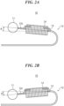
- FIGS. 2A and 2B are side views to illustrate power generation by the vibration power generation device 10 of FIGS. 1A to 1C .
- the vibration exciting body 11 vibrates in the vertical direction in the figure.
- the arm portion 12c warps upward and the magnetostrictive plate 13 attached to the upper surface of the arm portion 12c is compressed in the longitudinal direction of the arm portion 12c (see arrows in the figure).
- FIG. 2A when the vibration exciting body 11 moves upward, the arm portion 12c warps upward and the magnetostrictive plate 13 attached to the upper surface of the arm portion 12c is compressed in the longitudinal direction of the arm portion 12c (see arrows in the figure).
- Various methods are possible to vibrate the vibration exciting body 11 in the vertical direction.
- An example of a possible method is to place the vibration exciting body 11 in a fluid to create a Karman vortex downstream, causing the vibration exciting body 11 to vibrate vortically (vortex induced vibration).
- vortex induced vibration it is not known what fluid vibration phenomena occur in the vibration exciting body 11 when the vibration exciting body 11 is disposed in proximity to a wall surface of a structure or the like in a fluid.
- various fluidic effects can be obtained when an object is brought into close proximity to a wall surface or the like to narrow the flow path between the object and the wall surface.
- the inventors et al. conducted experiments using a circulating water tank to clarify what fluid vibration phenomena occur in the vibration exciting body 11 when the vibration exciting body 11 is disposed in proximity to a wall surface in a fluid.
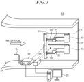
- FIG. 3 illustrates a schematic drawing of the configuration of a circulating water tank used in an experiment to observe the fluid vibration phenomena that occur when the vibration exciting body 11 of the vibration power generation device 10 is disposed in proximity to a wall surface.
- a vibration experimental device 17 that imitates the vibration power generation device 10 was fixed to a flat wall surface 16 of a circulating water tank 15 where a uniform water flow was occurring, indicated by the arrow in the figure.
- the vibration experimental device 17 has a columnar body 18 that imitates the vibration exciting body 11, and two U-shaped frames 19 that imitate the frames 12. In the vibration experimental device 17, each of the U-shaped frames 19 is not directly attached to the columnar body 18.
- the vibration experimental device 17 was disposed in the circulating water tank 15 so that the longitudinal direction of the columnar body 18 was orthogonal to the water flow, the columnar body 18 was parallel to the wall surface 16, and the longitudinal direction of each U-shaped frame 19 was parallel to the water flow. Since the purpose of this experiment was to observe fluid vibration phenomena, the vibration experimental device 17 was not provided with components equivalent to the magnetostrictive plate 13 and the coil 14. Furthermore, since the wall surface 16 of the circulating water tank 15 did not vibrate, the vibration in the columnar body 18 was not caused by the vibration of the wall surface 16, but only by the action of the fluid, such as the generation of vortices.
- a plurality of the height adjustment jigs 21 of different heights were prepared, and the distance S between the columnar body 18 and the wall surface 16 was changed by replacing the height adjustment jigs 21.
- a cylindrical member (sample 1) and three types of rectangular columnar members (samples 2 to 4) having cross sectional aspect ratios that differ from one another were prepared as the columnar body 18.
- vibrations occurred in the vibration experimental device 17 were observed when the distance S between the columnar body 18 and the wall surface 16 was changed.
- the samples 1 and 4 were made of stainless steel, while the samples 2 and 3 were made of Anviloy.
- the circulating water tank 15 includes a laser displacement meter 22, a laser Doppler velocimeter (LDV) 23, and a pitot tube 24.
- the laser displacement meter 22 measured the vibratory displacement of the columnar body 18 relative to the wall surface 16
- the LDV 23 measured the velocity variation of the water flow behind the columnar body 18,
- the pitot tube 24 measured the velocity U of the water relative to the wall surface 16.
- a computer 25 compiled the measurement results of the laser displacement meter 22, the LDV 23, and the pitot tube 24 to calculate the angle of deviation ⁇ of the vibration in the columnar body 18, vortex shedding frequency fw, and reduced velocity Vr to be described later.
- a cylindrical member as the sample 1 was used as the columnar body 18.
- the longitudinal length of the columnar body 18 is 200 mm.
- the total length r (see FIG. 4A ) of the vibration system (hereinafter referred to as the "experimental vibration system"), which includes the columnar body 18, the arm portion of the U-shaped frame 19, the height adjustment jig 21, and the arm 20, was 142 mm.
- the water velocity U was varied in the range of 0.4 m/s to 2.6 m/s, and the gap S between the wall surface 16 and the columnar body 18 was varied in steps to observe the vibration occurred in the columnar body 18.
- the gap spacing ratio S/H was varied in four steps of 0.5, 1.0, 2.0 and 3.0.
- the observation results of the vibration are illustrated in the graph in FIG. 4B .
- a waveform vibration with an angle of vibration ⁇ of 0.05 deg or more was observed, it was judged that vibration was occurring in the columnar body 18.
- the horizontal axis of the graph in FIG. 4B is the reduced velocity Vr, and the vertical axis is the angle of vibration ⁇ of the experimental vibration system (see FIGS. 2A and 2B ).
- the reduced velocity Vr is the dimensionless velocity of water corrected for the effect of the blockage of water flowing between the wall surface 16 and the columnar body 18.
- the natural frequency of the experimental vibration system is fc
- Vortex induced vibration is expected to increase the vibration of the columnar body 18 near the resonant reduced velocity, and the resonant reduced velocity is indicated by the dashed line in the graph in FIG. 4B .
- the maximum gap Smax is the gap S when the columnar body 18 is farthest from the wall surface 16
- the minimum gap Smin is the gap S when the columnar body 18 is closest to the wall surface 16.
- a rectangular columnar member as the sample 2 was used as the columnar body 18.
- the longitudinal length of the columnar body 18 is 200 mm.
- the length H of the columnar body 18 in the direction orthogonal to the wall surface 16 was 20 mm, and the length D in the direction parallel to the direction of water flow was 4 mm. That is, the aspect ratio D/H of the columnar body 18 was set to 0.2.
- the total length r of the experimental vibration system was 172 mm.
- Experiment 2 as in Experiment 1, the water velocity U was varied in the range of 0.4 m/s to 2.6 m/s, and the gap spacing ratio S/H was varied in four steps of 0.5, 1.0, 2.0, and 3.0, and the vibration occurred in the columnar body 18 was observed. Also in Experiment 2, when a waveform vibration with an angle of vibration ⁇ of 0.05 deg or more was observed, it was determined that the columnar body 18 was vibrating.
- FIG. 5B is a graph illustrating the observation results of vibration of the columnar body 18 when the aspect ratio D/H of the columnar body 18 is 0.2.
- the description of the vertical and horizontal axes in FIG. 5B is the same as that of the vertical and horizontal axes of the graph in FIG. 4B .
- the resonant reduced velocity in Experiment 2 is approximately 7.3, which is indicated by the dashed line in the graph in FIG. 5B .
- the longitudinal length of the columnar body 18 is 200 mm.
- the total length r of the experimental vibration system was 142 mm.
- Experiment 3 as in Experiment 1, the water velocity U was varied in the range of 0.4 m/s to 2.6 m/s, and the gap spacing ratio S/H was varied in four steps of 0.5, 1.0, 2.0, and 3.0, and the vibration occurred in the columnar body 18 was observed. Also in Experiment 3, when a waveform vibration with an angle of vibration ⁇ of 0.05 deg or more was observed, it was determined that the columnar body 18 was vibrating.
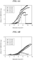
- FIG. 6A is a graph illustrating the observation results of vibration of the columnar body 18 when the aspect ratio D/H of the columnar body 18 is 0.5.
- the description of the vertical and horizontal axes in FIG. 6A is the same as that of the vertical and horizontal axes of the graph in FIG. 4B .
- the resonant reduced velocity in Experiment 3 is approximately 7.2, which is indicated by the dashed line in the graph in FIG. 6A .
- a rectangular columnar member as the sample 4 was used as the columnar body 18.
- the longitudinal length of the columnar body 18 is 200 mm.
- the total length r of the experimental vibration system was 142 mm.
- Experiment 4 as in Experiment 1, the water velocity U was varied in the range of 0.4 m/s to 2.6 m/s, and the gap spacing ratio S/H was varied in four steps of 0.5, 1.0, 2.0, and 3.0, and the vibration occurred in the columnar body 18 was observed. Also in Experiment 4, when a waveform vibration with an angle of vibration ⁇ of 0.05 deg or more was observed, it was determined that the columnar body 18 was vibrating.
- FIG. 6B is a graph illustrating the observation results of vibration of the columnar body 18 when the aspect ratio D/H of the columnar body 18 is 1.0.
- the description of the vertical and horizontal axes in FIG. 6B is the same as that of the vertical and horizontal axes of the graph in FIG. 4B .
- the resonant reduced velocity in Experiment 4 is approximately 7.3, which is indicated by the dashed line in the graph in FIG. 6B .
- the vibration exciting body 11 is disposed in proximity to a wall surface 26 of the structure or moving object to which the base portion 12b of the frame 12 is attached, in the flow of a fluid such as gas or water.
- the cross-sectional shape of the vibration exciting body 11 is rectangular and the aspect ratio D/H of the cross-sectional shape is 0.5, as indicated in the observation results of Experiment 3, keeping the reduced velocity Vr of the fluid 3.0 or more can generate vibration in the vibration exciting body 11 and further improve the power generation efficiency of the vibration power generation device 10.
- the present embodiment is based on the findings of Experiments 1 to 4, which were conducted using the columnar bodies 18 with an aspect ratio D/H of 1.0 or less, the aspect ratio D/H of the vibration exciting body 11 is also preferably 1.0 or less (D/H ⁇ 1.0). Since the present embodiment is based on the findings of Experiments 1 to 4, in which the wall surface 16 of the circulating water tank 15 do not vibrate, it is assumed that the wall surface of the structure or moving object to which the base portion 12b of the frame 12 is attached do not vibrate.
- the vibration exciting body 11 by disposing the vibration exciting body 11 in proximity to the wall surface, low-speed galloping vibration can be generated at a low reduced velocity Vr, which allows the vibration exciting body 11 to vibrate even in a large vibration power generation device 10, where the natural frequency is lower.
- Vr reduced velocity
- the use of a large vibration power generation device 10 can further improve power generation efficiency due to the synergistic effect of the larger size of the vibration power generation device 10 and the expanded range of reduced velocities at which the vibration exciting body 11 vibrates.
- the vibration power generation device 10 has two frames 12, but the number of the frames 12 is not limited to two, but may be one, three, or more.
- the power generation efficiency can be improved by providing the magnetostrictive plate 13 and the coil 14 on each of the frames 12.
- the oscillation of the arm portion 12c was used to expand and compress the magnetostrictive plate 13 to generate electricity.
- a piezoelectric element may be provided instead of the magnetostrictive plate 13, and power may be generated by deforming the piezoelectric element using the oscillation of the arm portion 12c.
- a magnetic material may be provided instead of the magnetostrictive plate 13, and the arm portion 12c may be configured to move the magnetic material relative to the coil using the oscillation of the arm portion 12c to generate electricity by electromagnetic induction.
- the arm portion 12c of the vibration power generation device 10 itself may be made of a magnetostrictive material and the magnetostrictive plate 13 may be eliminated.
- the vibration exciting body 11 of the vibration power generation device 10 is not limited to a columnar body with a circular or rectangular cross section, but may also be a columnar body with a polygonal cross section other than rectangular (a square/quadrangular).
- the vibration experimental device 17 was attached to the wall surface 16 so that the bend portion of the U-shaped frame 19 was disposed downstream of the water flow, but the location of the bend portion is not limited.
- the bend portion 12a of the frame 12 may be disposed upstream of the fluid from the vibration exciting body 11.
- the arm portion 12c of the frame 12 is disposed parallel to the wall surface 26, but the arm portion 12c does not have to be disposed parallel to the wall surface 26 as long as the vibration exciting body 11 is disposed in proximity to the wall surface 26 and the arm portion 12c is oscillatable. Similarly, the arm portion 12c does not have to be disposed parallel to the direction of the fluid flow.
- FIGS. 7A and 7B illustrate a wind following plate 27 with the vibration power generation device 10 applied thereto.
- the wind following plate 27 is vertically erected against a disk-shaped base 28 and is configured to be rotatable around the central axis of the base 28.
- the axis of rotation of the wind following plate 27 is set offset from the center of the wind following plate 27. Therefore, when the wind following plate 27 is disposed in a fluid flow, for example, an air flow, the wind following plate 27 changes its orientation so that its surface is substantially parallel to the direction of the air flow (see white arrows in the figure). That is, the wind following plate 27 changes its direction following the air flow.
- the vibration power generation device 10 is disposed so that the longitudinal direction of the vibration exciting body 11 is substantially orthogonal to the air flow, the vibration exciting body 11 is substantially parallel to the surface of the wind following plate 27, and the longitudinal direction of each of the frames 12 is substantially parallel to the air flow.
- the probability of air flow on the surface of the wind following plate 27 can be increased. This can increase the frequency at which the vibration exciting body 11 of the vibration power generation device 10 vibrates, thereby further improving the power generation efficiency by the vibration power generation device 10.
- each vibration power generation device 10 has is not limited to two; each vibration power generation device 10 may have three or more frames 12 and coils 14, as shown in FIG. 7B .
- the magnetostrictive plate 13 is not illustrated.
- FIG. 8 illustrates an aircraft 29 to which the vibration power generation device 10 is applied.
- the vibration power generation device 10 is disposed on the surface of each main wing 30 of the aircraft 29.
- the magnetostrictive plate 13 and the coil 14 are not illustrated.
- the vibration exciting body 11 is disposed near the leading edge of each of the main wings 30 so that its longitudinal direction is along the leading edge of the main wings 30.
- the vibration power generation device 10 is disposed on each of the main wing 30 so that the vibration exciting body 11 is substantially parallel to the surface of the main wing 30, and the longitudinal direction of each of the frames 12 is substantially parallel to the air flow.
- the vibration exciting body 11 is disposed near the leading edge of each of the main wings 30, the vibration exciting body 11 also can function as a vortex generator to reduce atmospheric drag.
- the location of the vibration power generation device 10 is not limited to the surface of the main wings 30.
- the vibration power generation device 10 may be disposed on any surface of the aircraft 29 as long as the location does not interfere with flight or takeoff/landing.
- FIG. 9 illustrates a portion of a train 31 to which the vibration power generation device 10 is applied.
- the vibration power generation device 10 is disposed on the surface of a sound insulation plate 33 that insulates the wind noise of a pantograph 32 of the train 31.
- the magnetostrictive plate 13 and the coil 14 are not illustrated.
- the vibration power generation device 10 is disposed on the sound insulation plate 33 so that the longitudinal direction of the vibration exciting body 11 is substantially orthogonal to the air flow generated while the the train 31 is running, the vibration exciting body 11 is substantially parallel to the surface of the sound insulation plate 33, and the longitudinal direction of each of the frames 12 is substantially parallel to the above air flow.
- the location of the vibration power generation device 10 is not limited to the surface of the sound insulation plate 33.
- the vibration power generation device 10 may be disposed on anywhere of the train 31 vehicle surfaces as long as the location does not interfere with running.
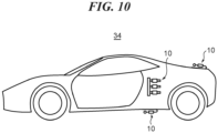
- FIG. 10 illustrates an automobile 34 to which the vibration power generation device 10 is applied.
- the vibration power generation device 10 is disposed on the surface of the automobile 34.
- the magnetostrictive plate 13 is not illustrated.
- the reference signs for the vibration exciting body 11, the frame 12, and the coil 14 are also omitted.
- the vibration power generation device 10 is disposed on the surface of the vehicle so that the longitudinal direction of the vibration exciting body 11 is substantially orthogonal to the air flow generated while the automobile 34 is running, the vibration exciting body 11 is substantially parallel to the vehicle surface, and the longitudinal direction of each of the frames 12 is substantially parallel to the above air flow.
- the automobile 34 is not limited to a four-wheeled vehicle as illustrated in FIG. 10 , but may also be a three-wheeled vehicle or other multi-wheeled vehicle.
- FIG. 11 illustrates a motorcycle 35 as a saddle-riding vehicle to which the vibration power generation device 10 is applied.
- the vibration power generation device 10 is disposed on the surface of the motorcycle 35.
- the magnetostrictive plate 13 is not illustrated.
- the reference signs for the vibration exciting body 11, the frame 12, and the coil 14 are also omitted.
- the vibration power generation device 10 is disposed on the surface of the vehicle so that the longitudinal direction of the vibration exciting body 11 is substantially orthogonal to the air flow generated while the motorcycle 35 is running, the vibration exciting body 11 is substantially parallel to the vehicle surface, and the longitudinal direction of each of the frames 12 is substantially parallel to the above air flow.
- the saddle-riding vehicle to which the vibration power generation device 10 is applied is not limited to the motorcycle 35 illustrated in FIG. 11 , but may also be a three-wheeled vehicle or an all terrain vehicle (ATV).
- FIG. 12 illustrates a marine vessel 36 to which the vibration power generation device 10 is applied.
- the vibration power generation device 10 is disposed on the surface of a hull 37 or a cabin 38 of the marine vessel 36.
- the magnetostrictive plate 13 is not illustrated.
- the reference signs for the vibration exciting body 11, the frame 12, and the coil 14 are also omitted.
- the vibration power generation device 10 is disposed on the surface of the hull 37 or the cabin 38 so that the longitudinal direction of the vibration exciting body 11 is substantially orthogonal to the flow of air or water generated while the marine vessel 36 is traveling, the vibration exciting body 11 is substantially parallel to the surface of the hull 37 or cabin 38, and the longitudinal direction of each of the frames 12 is substantially parallel to the flow of air or water.
- the vibration power generation device 10 when the vibration power generation device 10 is disposed on the surface of the hull 37 below the water surface, the fluid acting on the vibration exciting body 11 is water. In this case, since the water has a higher density than the air, the variation in the pressure on the vibration exciting body 11 is greater, which allows the vibration exciting body 11 to vibrate more efficiently, resulting in further improvement of the power generation efficiency of the vibration power generation device 10.
- the location of the vibration power generation device 10 is not limited to the surface of the hull 37 or the cabin 38.
- the vibration power generation device 10 may be disposed on the surface of a trim tab 39 for posture control.
- FIGS. 13A and 13B illustrate an outboard motor 40 to which the vibration power generation device 10 is applied.
- FIG. 13A is a side view of the outboard motor 40 and
- FIG. 13B is a bottom view of the outboard motor 40.
- the vibration power generation device 10 is disposed on the lower surface of an anti-ventilation plate 41 of the outboard motor 40.
- the magnetostrictive plate 13 is not illustrated.
- the reference signs for the vibration exciting body 11, the frame 12, and the coil 14 are also omitted.
- the vibration power generation device 10 is disposed on the lower surface of the anti-ventilation plate 41 so that the longitudinal direction of the vibration exciting body 11 is substantially orthogonal to the water flow that generated while the marine vessel equipped with the outboard motor 40 is traveling, the vibration exciting body 11 is substantially parallel to the lower surface of the anti-ventilation plate 41, and the longitudinal direction of each of the frames 12 is substantially parallel to the water flow.
- FIG. 14 illustrates a portion of a marine vessel to which the vibration power generation device 10 is applied.
- the vibration power generation device 10 is disposed upstream of a propeller 42 that is configured to generate a propulsive force.
- the vibration power generation device 10 is disposed on the surface of each of a plurality of stators 43, which are fin-like members that control the water flow into the propeller 42 to reduce the rotational flow by the propeller 42.
- the magnetostrictive plate 13 is not illustrated.
- the reference signs for the vibration exciting body 11, the frame 12, and the coil 14 are also omitted.
- the vibration power generation device 10 is disposed on the surface of each of the stators 43 so that the longitudinal direction of the vibration exciting body 11 is substantially orthogonal to the water flow generated while the marine vessel is traveling, the vibration exciting body 11 is substantially parallel to the surface of each of the stators 43, and the longitudinal direction of each of the frames 12 is substantially parallel to the water flow.
- FIGS. 15A and 15B illustrate a duct propeller mechanism 45 of a marine vessel to which the vibration power generation device 10 is applied.
- FIG. 15A is a perspective view illustrating duct propeller mechanism 45
- FIG. 15B is a cross-sectional view of duct propeller mechanism 45.
- the vibration power generation device 10 is disposed on the inner surface of a duct 46 of the duct propeller mechanism 45.
- the magnetostrictive plate 13 is not illustrated.
- the reference signs for the vibration exciting body 11, the frame 12, and the coil 14 are also omitted.
- the vibration power generation device 10 is disposed on the inner surface of the duct 46 so that the longitudinal direction of the vibration exciting body 11 is substantially orthogonal to the water flow through inside of the duct 46, the vibration exciting body 11 is substantially parallel to the inner surface of the duct 46, and the longitudinal direction of each of the frames 12 is substantially parallel to the water flow.
- the vibration power generation device 10 may be installed on the surface of a dam or dike through which water flows, or on the inner surface of a water intake pipe, water conduit, or water pipe.
- the vibration power generation device 10 may be installed on the surface of a high-rise building or tower that is exposed to the wind and where air flow is constantly present.
Landscapes
- General Electrical Machinery Utilizing Piezoelectricity, Electrostriction Or Magnetostriction (AREA)
- Apparatuses For Generation Of Mechanical Vibrations (AREA)
Abstract
Description
- The present invention relates to a vibration power generation device and a moving object.
- In recent years, various vibration power generation devices that generate power by electromagnetic induction or piezoelectric phenomenon using vibration have been developed. For example, a vibration power generation device has been proposed in which a weight is installed at the end of a magnetostrictive rod wound with a coil, and the vibration of the weight causes the magnetostrictive rod to vibrates, and partially expand and contract, generating electricity through the reverse magnetostriction effect (for example, see International Publication
WO 2011/158473 ). - As a method of vibrating a weight in such a vibration power generation device, it is conceivable to place the weight in a fluid to generate a Karman vortex to cause selfexcitation vibration of the weight. In this case, when the vibration frequency of the weight caused by the Karman vortex (vortex shedding frequency) matches the natural frequency of the vibration system consisting of the weight and magnetostrictive rod, a lock-in phenomenon occurs and the weight vibrates significantly, thus improving the power generation efficiency of the vibration power generation device.
- However, it is known that, for example, if the weight is cylindrical, the Strouhal number is almost constant, and as the fluid flow velocity changes, the vortex shedding frequency also changes. As a result, it is difficult to maintain a state in which the vortex shedding frequency matches the natural frequency of the vibration system consisting of weights and magnetostrictive rods, and the power generation efficiency of the vibration power generation device may decrease. Therefore, the conventional vibration power generation devices still have room for improvement in terms of power generation efficiency.
- An object of the present invention to provide a vibration power generation device and a moving object having high power generation efficiency.
- According to the present invention said object is solved by a vibration power generation device having the features of
independent claim 1. Moreover, according to the present invention said object is solved by a moving object having the features ofindependent claim 12. Preferred embodiments are laid down in the dependent claims. - According to a preferred embodiment, a vibration power generation device, comprises a vibration exciting body in which vibration is caused by a flowing fluid, a vibrated body which is oscillatable and is connected to the vibration exciting body, and a power generator that generates electricity by oscillation of the vibrated body, wherein the vibration exciting body is disposed in proximity to a wall surface, and vibration is caused in the vibration exciting body by a fluid flowing along the wall surface.
- According to this configuration, the vibration exciting body is disposed in proximity to the wall surface, which aids the vibration of the vibration exciting body, thus increasing the vibration of the vibration exciting body even outside of the flow velocity range where lock-in phenomenon is associated. That is, even if the vortex shedding frequency of the vibration exciting body does not match the natural frequency of the vibration system consisting of the vibration exciting body and the vibrated body, the vibration exciting body can be sufficiently vibrated, which can further improve the power generation efficiency.
- Further features of the present invention will become apparent from the following description of preferred embodiments with reference to the attached drawings.
- The above and other elements, features, steps, characteristics and advantages of the present teaching will become more apparent from the following detailed description of the preferred embodiments with reference to the attached drawings.
-
-
FIGS. 1A to 1C illustrate the configuration of the vibration power generation device according to an embodiment of the present teaching. -
FIGS. 2A and 2B are side views to illustrate power generation by the vibration power generation device ofFIGS. 1A to 1C . -
FIG. 3 shows a schematic drawing of the configuration of a circulating water tank used in an experiment to observe fluid vibration phenomena that occur when the vibration exciting body of a vibration power generation device is disposed in proximity to a wall surface. -
FIGS. 4A and 4B illustrate the observation results of fluid vibration phenomena when a cylindrical member is used as a columnar body. -
FIGS. 5A and 5B illustrate the observation results of fluid vibration phenomena when a rectangular columnar member is used as a columnar body. -
FIGS. 6A and 6B illustrate the observation results of fluid vibration phenomena when a rectangular columnar member is used as a columnar body. -
FIGS. 7A and 7B illustrate a wind following plate with the vibration power generation device applied thereto. -
FIG. 8 illustrates an aircraft to which the vibration power generation device is applied. -
FIG. 9 illustrates a portion of a train to which the vibration power generation device is applied. -
FIG. 10 illustrates an automobile to which the vibration power generation device is applied. -
FIG. 11 illustrates a motorcycle as a saddle-riding vehicle to which the vibration power generation device is applied. -
FIG. 12 illustrates a marine vessel to which the vibration power generation device is applied. -
FIGS. 13A and 13B illustrate an outboard motor to which the vibration power generation device is applied. -
FIG. 14 illustrates a portion of a marine vessel to which the vibration power generation device is applied. -
FIGS. 15A and 15B illustrate a duct propeller mechanism of a marine vessel to which the vibration power generation device is applied. - Hereinafter, preferred embodiments of the present teaching will be described with reference to the drawings.
-
FIGS. 1A to 1C illustrate the configuration of the vibration power generation device according to an embodiment of the present teaching.FIG. 1A is a side view of the vibration power generation device,FIG. 1B is a plan view of the vibration power generation device, andFIG. 1C is a side view of a modification of the vibration power generation device. - In
FIGS. 1A and 1B , a vibrationpower generation device 10 has a vibrationexciting body 11, which is a long weight, and two long plate-shaped frames 12 connected at one end to the vibrationexciting body 11. Theframes 12 are disposed parallel to each other in plan view. A bar-shapedmagnetostrictive plate 13 is attached to each of theframes 12, and acoil 14 is wound around theframe 12 and themagnetostrictive plate 13. Themagnetostrictive plate 13 and thecoil 14 constitute a power generator. - The
frames 12 are made of a magnetic material, for example, carbon steel (SS400 material, SC material, or SK material) or ferritic stainless steel (for example, SUS430). Theframes 12 are U-shaped in lateral view. In theframes 12, the portions facing each other through abend portion 12a constitutes abase portion 12b and anarm portion 12c (vibrated body), respectively. Thebase portion 12b is attached and fixed to a structure or moving object. In the present embodiment, the structure or moving object to which thebase portion 12b is attached does not actively vibrate. The vibrationexciting body 11 is attached to the end of thearm portion 12c. Furthermore, themagnetostrictive plate 13 and thecoil 14 described above are attached to thearm portion 12c between the vibrationexciting body 11 and thebend portion 12a of theframe 12, but thearm portion 12c is not fixed to the structure or moving object. Thus, in theframe 12, thearm portion 12c functions as a cantilever beam with thebend portion 12a side as the fixed end and the vibrationexciting body 11 side as the free end. Therefore, when the vibrationexciting body 11 vibrates in the vertical direction inFIG. 1A , thearm portion 12c oscillates in the vertical direction inFIG. 1A around the fixed end due to the vibration of the vibrationexciting body 11. Theframes 12 may be channelshaped or V-shaped in lateral view. - The
magnetostrictive plate 13 is made of a ductile magnetostrictive material, and is made of, for example, an iron-gallium alloy, an iron-cobalt alloy, an Fe-AI alloy, or an Fe-Si-B alloy. Furthermore, a magnetostrictive material to which compressive stress has been applied by subjecting it to stress annealing treatment in advance may be used as the material constituting themagnetostrictive plate 13. The magnetostrictive material constituting themagnetostrictive plate 13 may be in an amorphous state as well as in a crystalline state. Themagnetostrictive plate 13 is attached to the outer surface of thearm portion 12c (the upper surface of thearm portion 12c inFIG. 1A ) by, for example, soldering, waxing, resistance welding, laser welding, or ultrasonic bonding. - The material constituting the vibration
exciting body 11 is not particularly limited, and is preferably a high specific gravity material such as Anviloy, in order to vibrate the vibrationexciting body 11 from low flow velocities. The vibrationexciting body 11 is constituted by a cylindrical member in this case; however, which may be a long member to which a plurality of theframes 12 can be attached, for example, a rectangular columnar member (FIG. 1C ). -
FIGS. 2A and 2B are side views to illustrate power generation by the vibrationpower generation device 10 ofFIGS. 1A to 1C . InFIGS. 2A and 2B , the vibrationexciting body 11 vibrates in the vertical direction in the figure. As illustrated inFIG. 2A , when the vibrationexciting body 11 moves upward, thearm portion 12c warps upward and themagnetostrictive plate 13 attached to the upper surface of thearm portion 12c is compressed in the longitudinal direction of thearm portion 12c (see arrows in the figure). As illustrated inFIG. 2B , when the vibrationexciting body 11 moves downward, thearm portion 12c warps downward and themagnetostrictive plate 13 attached to the upper surface of thearm portion 12c is extended in the longitudinal direction of thearm portion 12c (see arrows in the figure). That is, when the vibrationexciting body 11 vibrates in the vertical direction, the extension and compression of themagnetostrictive plate 13 is repeated. At this time, since compressive and tensile stresses act alternately on themagnetostrictive plate 13, changes in the magnetic flux flowing through theplate 13 are repeated due to the reverse magnetostriction effect. This causes a continuous change in the magnetic flux through thecoil 14, which generates an electromotive force in thecoil 14 to generate electricity. - Various methods are possible to vibrate the vibration
exciting body 11 in the vertical direction. An example of a possible method is to place the vibrationexciting body 11 in a fluid to create a Karman vortex downstream, causing the vibrationexciting body 11 to vibrate vortically (vortex induced vibration). However, it is not known what fluid vibration phenomena occur in the vibrationexciting body 11 when the vibrationexciting body 11 is disposed in proximity to a wall surface of a structure or the like in a fluid. On the other hand, it is known that various fluidic effects can be obtained when an object is brought into close proximity to a wall surface or the like to narrow the flow path between the object and the wall surface. - Therefore, the inventors et al. conducted experiments using a circulating water tank to clarify what fluid vibration phenomena occur in the vibration
exciting body 11 when the vibrationexciting body 11 is disposed in proximity to a wall surface in a fluid. -
FIG. 3 illustrates a schematic drawing of the configuration of a circulating water tank used in an experiment to observe the fluid vibration phenomena that occur when the vibrationexciting body 11 of the vibrationpower generation device 10 is disposed in proximity to a wall surface. InFIG. 3 , a vibrationexperimental device 17 that imitates the vibrationpower generation device 10 was fixed to aflat wall surface 16 of a circulatingwater tank 15 where a uniform water flow was occurring, indicated by the arrow in the figure. The vibrationexperimental device 17 has acolumnar body 18 that imitates the vibrationexciting body 11, and twoU-shaped frames 19 that imitate theframes 12. In the vibrationexperimental device 17, each of the U-shaped frames 19 is not directly attached to thecolumnar body 18. Twoarms 20 were attached to thecolumnar body 18, and a blockshapedheight adjustment jig 21 was sandwiched between each of thearms 20 and the U-shaped frames 19. The vibrationexperimental device 17 was disposed in the circulatingwater tank 15 so that the longitudinal direction of thecolumnar body 18 was orthogonal to the water flow, thecolumnar body 18 was parallel to thewall surface 16, and the longitudinal direction of eachU-shaped frame 19 was parallel to the water flow. Since the purpose of this experiment was to observe fluid vibration phenomena, the vibrationexperimental device 17 was not provided with components equivalent to themagnetostrictive plate 13 and thecoil 14. Furthermore, since thewall surface 16 of the circulatingwater tank 15 did not vibrate, the vibration in thecolumnar body 18 was not caused by the vibration of thewall surface 16, but only by the action of the fluid, such as the generation of vortices. - In the experiment, a plurality of the height adjustment jigs 21 of different heights were prepared, and the distance S between the
columnar body 18 and thewall surface 16 was changed by replacing the height adjustment jigs 21. In addition, a cylindrical member (sample 1) and three types of rectangular columnar members (samples 2 to 4) having cross sectional aspect ratios that differ from one another were prepared as thecolumnar body 18. For each of thesamples 1 to 4, vibrations occurred in the vibrationexperimental device 17 were observed when the distance S between thecolumnar body 18 and thewall surface 16 was changed. Thesamples samples - The circulating
water tank 15 includes alaser displacement meter 22, a laser Doppler velocimeter (LDV) 23, and apitot tube 24. Thelaser displacement meter 22 measured the vibratory displacement of thecolumnar body 18 relative to thewall surface 16, theLDV 23 measured the velocity variation of the water flow behind thecolumnar body 18, and thepitot tube 24 measured the velocity U of the water relative to thewall surface 16. Furthermore, acomputer 25 compiled the measurement results of thelaser displacement meter 22, theLDV 23, and thepitot tube 24 to calculate the angle of deviation θ of the vibration in thecolumnar body 18, vortex shedding frequency fw, and reduced velocity Vr to be described later. - First, as illustrated in
FIG. 4A , a cylindrical member as thesample 1 was used as thecolumnar body 18. The longitudinal length of thecolumnar body 18 is 200 mm. The cross-sectional shape of thecolumnar body 18, parallel to the direction of water flow and orthogonal to thewall surface 16, was circular, and the diameter H of the circular shape was 20 mm. The total length r (seeFIG. 4A ) of the vibration system (hereinafter referred to as the "experimental vibration system"), which includes thecolumnar body 18, the arm portion of theU-shaped frame 19, theheight adjustment jig 21, and thearm 20, was 142 mm. - In
Experiment 1, the water velocity U was varied in the range of 0.4 m/s to 2.6 m/s, and the gap S between thewall surface 16 and thecolumnar body 18 was varied in steps to observe the vibration occurred in thecolumnar body 18. Specifically, the gap spacing ratio S/H was varied in four steps of 0.5, 1.0, 2.0 and 3.0. The observation results of the vibration are illustrated in the graph inFIG. 4B . Here, when a waveform vibration with an angle of vibration θ of 0.05 deg or more was observed, it was judged that vibration was occurring in thecolumnar body 18. - The horizontal axis of the graph in
FIG. 4B is the reduced velocity Vr, and the vertical axis is the angle of vibration θ of the experimental vibration system (seeFIGS. 2A and 2B ). The reduced velocity Vr is the dimensionless velocity of water corrected for the effect of the blockage of water flowing between thewall surface 16 and thecolumnar body 18. When the natural frequency of the experimental vibration system is fc, the reduced velocity Vr is expressed by the following equation (1):
- In addition, the resonant reduced velocity was calculated from the vortex shedding frequency fw when no vibration occurred in the
columnar body 18 at a gap spacing ratio S/H = 3.0, and a resonant reduced velocity value of approximately 5.3 was obtained. Vortex induced vibration is expected to increase the vibration of thecolumnar body 18 near the resonant reduced velocity, and the resonant reduced velocity is indicated by the dashed line in the graph inFIG. 4B . - As a result of the observation, as illustrated in the graph in
FIG. 4B , for any gap spacing ratio S/H, vibration occurred in thecolumnar body 18 from the reduced velocity Vr ≈ 4.0, which is near the resonant reduced velocity, indicating that vibration is caused mainly by vortex induced vibration in the case of the cylindrical member. - At a gap spacing ratio S/H = 0.5, the experiment was stopped because the angle of vibration θ increased rapidly when the reduced velocity Vr exceeded 5.0 or so and the
columnar body 18 collided with thewall surface 16. At a gap spacing ratio S/H = 1.0, the angle of vibration θ increased until the reduced velocity Vr reached 6.5, after which the angle of vibration θ decreased, but thecolumnar body 18 was still vibrating even when the reduced velocity Vr was above 8.0. At a gap spacing ratio S/H = 2.0, the angle of vibration θ increased until the reduced velocity Vr reached 6.8, after which the angle of vibration θ decreased, but thecolumnar body 18 was still vibrating even when the reduced velocity Vr was above 8.0. At a gap spacing ratio S/H = 3.0, the angle of vibration θ increased until the reduced velocity Vr reached 6.8, after which the angle of vibration θ decreased, but thecolumnar body 18 was still vibrating until the reduced velocity Vr reached 8.0. - As can be seen from the graph in
FIG. 4B , the smaller the gap spacing ratio S/H, the larger the angle of vibration θ becomes and the wider the range of reduced velocity Vr over which vibration occurs in thecolumnar body 18. This is considered to be because the closer thecolumnar body 18, which is a cylindrical member, is to thewall surface 16, the larger the gap variation ratio, which is the ratio of the difference between the maximum gap Smax and the minimum gap Smin to the maximum gap Smax as expressed by the following equation (2), and thus the pressure variation of the water flow acting on thecolumnar body 18 also becomes larger, which contributes to vibration.
- The maximum gap Smax is the gap S when the
columnar body 18 is farthest from thewall surface 16, and the minimum gap Smin is the gap S when thecolumnar body 18 is closest to thewall surface 16. - Next, as illustrated in
FIG. 5A , a rectangular columnar member as thesample 2 was used as thecolumnar body 18. The longitudinal length of thecolumnar body 18 is 200 mm. The cross-sectional shape of thecolumnar body 18, parallel to the direction of water flow and orthogonal to thewall surface 16, was rectangular. Referring toFIG. 5A , the length H of thecolumnar body 18 in the direction orthogonal to thewall surface 16 was 20 mm, and the length D in the direction parallel to the direction of water flow was 4 mm. That is, the aspect ratio D/H of thecolumnar body 18 was set to 0.2. The total length r of the experimental vibration system was 172 mm. - In
Experiment 2, as inExperiment 1, the water velocity U was varied in the range of 0.4 m/s to 2.6 m/s, and the gap spacing ratio S/H was varied in four steps of 0.5, 1.0, 2.0, and 3.0, and the vibration occurred in thecolumnar body 18 was observed. Also inExperiment 2, when a waveform vibration with an angle of vibration θ of 0.05 deg or more was observed, it was determined that thecolumnar body 18 was vibrating. -
FIG. 5B is a graph illustrating the observation results of vibration of thecolumnar body 18 when the aspect ratio D/H of thecolumnar body 18 is 0.2. The description of the vertical and horizontal axes inFIG. 5B is the same as that of the vertical and horizontal axes of the graph inFIG. 4B . The resonant reduced velocity inExperiment 2 is approximately 7.3, which is indicated by the dashed line in the graph inFIG. 5B . - As illustrated in the graph in
FIG. 5B , at a gap spacing ratio S/H = 0.5, vibration occurred in thecolumnar body 18 when the reduced velocity Vr exceeded 2.0, and then the angle of vibration θ increased rapidly and thecolumnar body 18 collided with thewall surface 16, so the experiment was stopped. At a gap spacing ratio S/H = 1.0, vibration occurred in thecolumnar body 18 when the reduced velocity Vr exceeded 2.0, then the angle of vibration θ increased rapidly until the reduced velocity Vr reached 6.8, and then the angle of vibration θ was almost maintained until the reduced velocity Vr reached 8.5. At a gap spacing ratio S/H = 2.0, vibration occurred in thecolumnar body 18 when the reduced velocity Vr exceeded 2.0, then the angle of vibration θ increased rapidly after when the reduced velocity Vr exceeded 5.0, then the angle of vibration θ decreased when the reduced velocity Vr exceeded 7.0, and no vibration occurred in thecolumnar body 18 when the reduced velocity Vr exceeded 9.0. Also at a gap spacing ratio S/H = 3.0, vibration occurred in thecolumnar body 18 when the reduced velocity Vr exceeded 2.0, then the angle of vibration θ increased rapidly when the reduced velocity Vr exceeded 7.0, and then the angle of vibration θ decreased rapidly when the reduced velocity Vr exceeded 8.0, and no vibration occurred in thecolumnar body 18 when the reduced velocity Vr exceeded 9.5. - As can be seen from the graph in
FIG. 5B , inExperiment 2, except for the case where the gap spacing ratio S/H = 3.0, large vibration occurred in thecolumnar body 18 from the point when the reduced velocity Vr was much lower than the resonant reduced velocity. This is considered to be because the closer thecolumnar body 18, which was a rectangular columnar member, was to thewall surface 16, the larger the above-described gap variation ratio between thewall surface 16 and thecolumnar body 18 becomes, resulting in larger fluctuations in the pressure of the water flow acting on thecolumnar body 18, which in turn facilitated the generation of low-speed galloping vibrations. The absence of low-speed galloping vibration when the gap spacing ratio S/H = 3.0, where thecolumnar body 18 is disposed relatively far from thewall surface 16, was considered to support this consideration. - Next, a rectangular columnar member as the
sample 3 was used as thecolumnar body 18. The longitudinal length of thecolumnar body 18 is 200 mm. The cross-sectional shape of thecolumnar body 18, parallel to the direction of water flow and orthogonal to thewall surface 16, was rectangular. Referring toFIG. 5A , the length H of thecolumnar body 18 was 20 mm and the length D was 10 mm. That is, the aspect ratio D/H of thecolumnar body 18 was set to 0.5. The total length r of the experimental vibration system was 142 mm. - In
Experiment 3, as inExperiment 1, the water velocity U was varied in the range of 0.4 m/s to 2.6 m/s, and the gap spacing ratio S/H was varied in four steps of 0.5, 1.0, 2.0, and 3.0, and the vibration occurred in thecolumnar body 18 was observed. Also inExperiment 3, when a waveform vibration with an angle of vibration θ of 0.05 deg or more was observed, it was determined that thecolumnar body 18 was vibrating. -
FIG. 6A is a graph illustrating the observation results of vibration of thecolumnar body 18 when the aspect ratio D/H of thecolumnar body 18 is 0.5. The description of the vertical and horizontal axes inFIG. 6A is the same as that of the vertical and horizontal axes of the graph inFIG. 4B . The resonant reduced velocity inExperiment 3 is approximately 7.2, which is indicated by the dashed line in the graph inFIG. 6A . - As illustrated in the graph in
FIG. 6A , when the gap spacing ratio S/H = 0.5, vibration occurred in thecolumnar body 18 when the reduced velocity Vr exceeded 3.0, and when the reduced velocity Vr exceeded 8.0, the angle of vibration θ decreased once, after which the angle of vibration θ increased slightly, without decreasing significantly, until the reduced velocity Vr reached 10.0. At a gap spacing ratio S/H = 1.0, vibration occurred in thecolumnar body 18 when the reduced velocity Vr exceeded 3.0, and then the angle of vibration θ increased until the reduced velocity Vr reached 10. At a gap spacing ratio S/H = 2.0, vibration occurred in thecolumnar body 18 when the reduced velocity Vr exceeded 4.0, and then the angle of vibration θ increased until the reduced velocity Vr reached 11.0. Also at a gap spacing ratio S/H = 3.0, vibration occurred in thecolumnar body 18 when the reduced velocity Vr exceeded 4.0, then the angle of vibration θ increased until the reduced velocity Vr reached 9.0, and then the angle of vibration θ decreased rapidly when the reduced velocity Vr exceeded 9.0. - As can be seen from the graph in
FIG. 6A , inExperiment 3, vibrations occurred in thecolumnar body 18 from a reduced velocity Vr much lower than the resonant reduced velocity for all gap spacing ratios. As inExperiment 2, this is considered to be due to the proximity of thecolumnar body 18, which is a rectangular columnar member, to thewall surface 16, which facilitated the generation of low-speed galloping vibration. As illustrated in the graph ofFIG. 6A , the smaller the gap spacing ratio S/H, i.e., the closer thecolumnar body 18 is to thewall surface 16, the lower the region of the reduced velocity Vr from which low-speed galloping vibration is excited, which supports this consideration. At the gap spacing ratio S/H = 1.0 and S/H = 2.0, the angle of vibration θ did not decrease even after the reduced velocity Vr exceeded the resonant reduced velocity. This is considered to be due to the occurrence of high-speed galloping vibrations when the reduced velocity Vr exceeds the vicinity of the resonant reduced velocity where vortex induced vibration becomes dominant. - Next, a rectangular columnar member as the
sample 4 was used as thecolumnar body 18. The longitudinal length of thecolumnar body 18 is 200 mm. The cross-sectional shape of thecolumnar body 18, parallel to the direction of the water flow and orthogonal to thewall surface 16, was square. That is, both the length H and length D of thecolumnar body 18 illustrated inFIG. 5A are 20 mm, and the aspect ratio D/H ofcolumnar body 18 was set to 1.0. The total length r of the experimental vibration system was 142 mm. - In
Experiment 4, as inExperiment 1, the water velocity U was varied in the range of 0.4 m/s to 2.6 m/s, and the gap spacing ratio S/H was varied in four steps of 0.5, 1.0, 2.0, and 3.0, and the vibration occurred in thecolumnar body 18 was observed. Also inExperiment 4, when a waveform vibration with an angle of vibration θ of 0.05 deg or more was observed, it was determined that thecolumnar body 18 was vibrating. -
FIG. 6B is a graph illustrating the observation results of vibration of thecolumnar body 18 when the aspect ratio D/H of thecolumnar body 18 is 1.0. The description of the vertical and horizontal axes inFIG. 6B is the same as that of the vertical and horizontal axes of the graph inFIG. 4B . The resonant reduced velocity inExperiment 4 is approximately 7.3, which is indicated by the dashed line in the graph inFIG. 6B . - As illustrated in the graph in
FIG. 6B , when the gap spacing ratio S/H = 0.5, although vibration occurred in thecolumnar body 18 when the reduced velocity Vr exceeded 4.0, the angle of vibration θ did not increase until the reduced velocity Vr exceeded 6.4, and although the angle of vibration θ increased somewhat near the resonant reduced velocity, the angle of vibration θ decreased thereafter as the reduced velocity Vr increased. On the other hand, in any case of gap spacing ratios S/H = 1.0, 2.0, and 3.0, vibration occurred in thecolumnar body 18 when the reduced velocity Vr exceeded 4.0, and then the angle of vibration θ increased even when the reduced velocity Vr exceeded 10. - As can be seen from the graph in
FIG. 6B , also inExperiment 4, low-speed galloping vibration was excited by the proximity of thecolumnar body 18, which is a rectangular columnar member, to thewall surface 16 at all gap spacing ratios. At the gap spacing ratio S/H = 0.5 inExperiment 4, the angle of vibration θ decreased after the reduced velocity Vr exceeded the resonant reduced velocity, and the similar tendency was observed at the gap spacing ratio S/H = 0.5 inExperiment 3, while at the gap spacing ratios S/H = 1.0, 2.0, and 3.0 inExperiment 4, the angle of vibration θ increased after the reduced velocity Vr exceeded the resonant reduced velocity, and a similar tendency was observed at the gap spacing ratios S/H = 1.0 and 2.0 inExperiment 3. This also indicates that excessive proximity of thecolumnar body 18 to thewall surface 16 is not desirable to generate high-speed galloping vibrations. - The observation results from
Experiments 1 to 4 yielded the following findings. By disposing thecolumnar body 18 in a water flow in proximity to thewall surface 16, the gap variation ratio increases, and the pressure variation of the water flow acting on thecolumnar body 18 also increases. Therefore, not only vortex induced vibration occurring near the resonant reduced velocity, but also low-speed galloping vibration can be generated at low reduced velocities. In addition, under some conditions, high velocity galloping vibration can be generated even when the reduced velocity exceeds the resonant reduced velocity. As a result, the vibration of thecolumnar body 18 can be maintained even when the water velocity changes. - Applying this finding to the vibration
power generation device 10, in an embodiment of the present teaching, the vibrationexciting body 11 is disposed in proximity to awall surface 26 of the structure or moving object to which thebase portion 12b of theframe 12 is attached, in the flow of a fluid such as gas or water. In particular, based on the observation results ofExperiments 1 to 4, (here, the distance between thewall surface 26 and the vibrationexciting body 11 is put as a gap S, and the length of the vibrationexciting body 11 in the direction orthogonal to thewall surface 26 is put as a length H), by setting the gap spacing ratio S/H to 3.0 or less, the gap variation ratio increases and the pressure variation of the fluid acting on thecolumnar body 18 also increases, which allows low-speed galloping vibrations to be generated at low reduced velocities, and thus the vibration of the vibrationexciting body 11 can be maintained even when the fluid flow velocity changes. As a result, the power generation efficiency of the vibrationpower generation device 10 can be further improved. - More specifically, in the embodiment of the present teaching, when the cross-sectional shape of the vibration
exciting body 11 parallel to the fluid flow direction and orthogonal to the wall surface is circular, as indicated in the observation results ofExperiment 1, keeping the reduced velocity Vr of the fluid 4.0 or more can generate vibration in the vibrationexciting body 11 and further improve the power generation efficiency of the vibrationpower generation device 10. - When the cross-sectional shape of the vibration
exciting body 11 parallel to the fluid flow direction and orthogonal to the wall surface is rectangular and the aspect ratio D/H of the cross-sectional shape is 0.2, as indicated in the observation results ofExperiment 2, keeping the reduced velocity Vr of the fluid 2.0 or more can generate vibration in the vibrationexciting body 11 and further improve the power generation efficiency of the vibrationpower generation device 10. - Furthermore, when the cross-sectional shape of the vibration
exciting body 11 is rectangular and the aspect ratio D/H of the cross-sectional shape is 0.5, as indicated in the observation results ofExperiment 3, keeping the reduced velocity Vr of the fluid 3.0 or more can generate vibration in the vibrationexciting body 11 and further improve the power generation efficiency of the vibrationpower generation device 10. - When the cross-sectional shape of the vibration
exciting body 11 is rectangular and the aspect ratio D/H of the cross-sectional shape is 1.0, as indicated in the observation results ofExperiment 4, keeping the reduced velocity Vr of the fluid 4.0 or more can generate vibration in the vibrationexciting body 11 and further improves the power generation efficiency of the vibrationpower generation device 10. - Since the present embodiment is based on the findings of
Experiments 1 to 4, which were conducted using thecolumnar bodies 18 with an aspect ratio D/H of 1.0 or less, the aspect ratio D/H of the vibrationexciting body 11 is also preferably 1.0 or less (D/H ≤ 1.0). Since the present embodiment is based on the findings ofExperiments 1 to 4, in which thewall surface 16 of the circulatingwater tank 15 do not vibrate, it is assumed that the wall surface of the structure or moving object to which thebase portion 12b of theframe 12 is attached do not vibrate. - According to the present embodiment, as described above, by disposing the vibration
exciting body 11 in proximity to the wall surface, low-speed galloping vibration can be generated at a low reduced velocity Vr, which allows the vibrationexciting body 11 to vibrate even in a large vibrationpower generation device 10, where the natural frequency is lower. As a result, the use of a large vibrationpower generation device 10 can further improve power generation efficiency due to the synergistic effect of the larger size of the vibrationpower generation device 10 and the expanded range of reduced velocities at which the vibrationexciting body 11 vibrates. - In the present embodiment, the vibration
power generation device 10 has twoframes 12, but the number of theframes 12 is not limited to two, but may be one, three, or more. When the number of theframes 12 is three or more, the power generation efficiency can be improved by providing themagnetostrictive plate 13 and thecoil 14 on each of theframes 12. - The preferred embodiments have been described above, but the present teaching is not limited to the above-described embodiments, and various variations and changes are possible within the scope of the gist of present teaching.
- For example, in the vibration
power generation device 10, the oscillation of thearm portion 12c was used to expand and compress themagnetostrictive plate 13 to generate electricity. As an alternative, a piezoelectric element may be provided instead of themagnetostrictive plate 13, and power may be generated by deforming the piezoelectric element using the oscillation of thearm portion 12c. Alternatively, a magnetic material may be provided instead of themagnetostrictive plate 13, and thearm portion 12c may be configured to move the magnetic material relative to the coil using the oscillation of thearm portion 12c to generate electricity by electromagnetic induction. Thearm portion 12c of the vibrationpower generation device 10 itself may be made of a magnetostrictive material and themagnetostrictive plate 13 may be eliminated. - The vibration
exciting body 11 of the vibrationpower generation device 10 is not limited to a columnar body with a circular or rectangular cross section, but may also be a columnar body with a polygonal cross section other than rectangular (a square/quadrangular). - In
Experiments 1 to 4, the vibrationexperimental device 17 was attached to thewall surface 16 so that the bend portion of theU-shaped frame 19 was disposed downstream of the water flow, but the location of the bend portion is not limited. For example, in the vibrationpower generation device 10, thebend portion 12a of theframe 12 may be disposed upstream of the fluid from the vibrationexciting body 11. - In the present embodiment, as illustrated in
FIGS. 1A to 1C , thearm portion 12c of theframe 12 is disposed parallel to thewall surface 26, but thearm portion 12c does not have to be disposed parallel to thewall surface 26 as long as the vibrationexciting body 11 is disposed in proximity to thewall surface 26 and thearm portion 12c is oscillatable. Similarly, thearm portion 12c does not have to be disposed parallel to the direction of the fluid flow. - The applications of the vibration
power generation device 10 are described below. -
FIGS. 7A and 7B illustrate awind following plate 27 with the vibrationpower generation device 10 applied thereto. InFIG. 7A , thewind following plate 27 is vertically erected against a disk-shapedbase 28 and is configured to be rotatable around the central axis of thebase 28. The axis of rotation of thewind following plate 27 is set offset from the center of thewind following plate 27. Therefore, when thewind following plate 27 is disposed in a fluid flow, for example, an air flow, thewind following plate 27 changes its orientation so that its surface is substantially parallel to the direction of the air flow (see white arrows in the figure). That is, thewind following plate 27 changes its direction following the air flow. On each of the two sides of thewind following plate 27, the vibrationpower generation device 10 is disposed so that the longitudinal direction of the vibrationexciting body 11 is substantially orthogonal to the air flow, the vibrationexciting body 11 is substantially parallel to the surface of thewind following plate 27, and the longitudinal direction of each of theframes 12 is substantially parallel to the air flow. - Since the
wind following plate 27 follows the air flow, the probability of air flow on the surface of thewind following plate 27 can be increased. This can increase the frequency at which the vibrationexciting body 11 of the vibrationpower generation device 10 vibrates, thereby further improving the power generation efficiency by the vibrationpower generation device 10. - Each of the number of the
frames 12 and the number of thecoils 14 that each vibrationpower generation device 10 has is not limited to two; each vibrationpower generation device 10 may have three ormore frames 12 and coils 14, as shown inFIG. 7B . InFIGS. 7A and 7B , themagnetostrictive plate 13 is not illustrated. -
FIG. 8 illustrates anaircraft 29 to which the vibrationpower generation device 10 is applied. InFIG. 8 , the vibrationpower generation device 10 is disposed on the surface of eachmain wing 30 of theaircraft 29. InFIG. 8 , themagnetostrictive plate 13 and thecoil 14 are not illustrated. - In the
aircraft 29, the vibrationexciting body 11 is disposed near the leading edge of each of themain wings 30 so that its longitudinal direction is along the leading edge of themain wings 30. The vibrationpower generation device 10 is disposed on each of themain wing 30 so that the vibrationexciting body 11 is substantially parallel to the surface of themain wing 30, and the longitudinal direction of each of theframes 12 is substantially parallel to the air flow. During the flight of theaircraft 29, there is a constant air flow on the surfaces of themain wings 30, which allows the vibrationexciting body 11 to vibrate constantly, thereby further improving the power generation efficiency of the vibrationpower generation device 10. Since the long vibrationexciting body 11 is disposed near the leading edge of each of themain wings 30, the vibrationexciting body 11 also can function as a vortex generator to reduce atmospheric drag. The location of the vibrationpower generation device 10 is not limited to the surface of themain wings 30. The vibrationpower generation device 10 may be disposed on any surface of theaircraft 29 as long as the location does not interfere with flight or takeoff/landing. -
FIG. 9 illustrates a portion of atrain 31 to which the vibrationpower generation device 10 is applied. InFIG. 9 , the vibrationpower generation device 10 is disposed on the surface of asound insulation plate 33 that insulates the wind noise of apantograph 32 of thetrain 31. InFIG. 9 , themagnetostrictive plate 13 and thecoil 14 are not illustrated. - In the
train 31, the vibrationpower generation device 10 is disposed on thesound insulation plate 33 so that the longitudinal direction of the vibrationexciting body 11 is substantially orthogonal to the air flow generated while the thetrain 31 is running, the vibrationexciting body 11 is substantially parallel to the surface of thesound insulation plate 33, and the longitudinal direction of each of theframes 12 is substantially parallel to the above air flow. There is a constant air flow on the surface of thesound insulation plate 33 while thetrain 31 is running, which allows the vibrationexciting body 11 to vibrate constantly, thereby further improving the power generation efficiency of the vibrationpower generation device 10. The location of the vibrationpower generation device 10 is not limited to the surface of thesound insulation plate 33. The vibrationpower generation device 10 may be disposed on anywhere of thetrain 31 vehicle surfaces as long as the location does not interfere with running. -
FIG. 10 illustrates anautomobile 34 to which the vibrationpower generation device 10 is applied. InFIG. 10 , the vibrationpower generation device 10 is disposed on the surface of theautomobile 34. InFIG. 10 , themagnetostrictive plate 13 is not illustrated. The reference signs for the vibrationexciting body 11, theframe 12, and thecoil 14 are also omitted. - In the
automobile 34, the vibrationpower generation device 10 is disposed on the surface of the vehicle so that the longitudinal direction of the vibrationexciting body 11 is substantially orthogonal to the air flow generated while theautomobile 34 is running, the vibrationexciting body 11 is substantially parallel to the vehicle surface, and the longitudinal direction of each of theframes 12 is substantially parallel to the above air flow. There is a constant air flow on the surface of the vehicle while theautomobile 34 is running, which allows the vibrationexciting body 11 to constantly vibrate, thereby further improving the power generation efficiency of the vibrationpower generation device 10. Theautomobile 34 is not limited to a four-wheeled vehicle as illustrated inFIG. 10 , but may also be a three-wheeled vehicle or other multi-wheeled vehicle. -
FIG. 11 illustrates amotorcycle 35 as a saddle-riding vehicle to which the vibrationpower generation device 10 is applied. InFIG. 11 , the vibrationpower generation device 10 is disposed on the surface of themotorcycle 35. InFIG. 11 , themagnetostrictive plate 13 is not illustrated. The reference signs for the vibrationexciting body 11, theframe 12, and thecoil 14 are also omitted. - In the
motorcycle 35, the vibrationpower generation device 10 is disposed on the surface of the vehicle so that the longitudinal direction of the vibrationexciting body 11 is substantially orthogonal to the air flow generated while themotorcycle 35 is running, the vibrationexciting body 11 is substantially parallel to the vehicle surface, and the longitudinal direction of each of theframes 12 is substantially parallel to the above air flow. There is a constant air flow on the surface of the vehicle while themotorcycle 35 is running, which allows the vibrationexciting body 11 to constantly vibrate, thereby further improving the power generation efficiency of the vibrationpower generation device 10. The saddle-riding vehicle to which the vibrationpower generation device 10 is applied is not limited to themotorcycle 35 illustrated inFIG. 11 , but may also be a three-wheeled vehicle or an all terrain vehicle (ATV). -
FIG. 12 illustrates amarine vessel 36 to which the vibrationpower generation device 10 is applied. InFIG. 12 , the vibrationpower generation device 10 is disposed on the surface of ahull 37 or acabin 38 of themarine vessel 36. InFIG. 12 , themagnetostrictive plate 13 is not illustrated. The reference signs for the vibrationexciting body 11, theframe 12, and thecoil 14 are also omitted. - In the
marine vessel 36, the vibrationpower generation device 10 is disposed on the surface of thehull 37 or thecabin 38 so that the longitudinal direction of the vibrationexciting body 11 is substantially orthogonal to the flow of air or water generated while themarine vessel 36 is traveling, the vibrationexciting body 11 is substantially parallel to the surface of thehull 37 orcabin 38, and the longitudinal direction of each of theframes 12 is substantially parallel to the flow of air or water. There is a constant flow of air or water on the surface of thehull 37 and thecabin 38 while themarine vessel 36 is traveling, which allows the vibrationexciting body 11 to vibrate constantly, thereby further improving the power generation efficiency of the vibrationpower generation device 10. In particular, when the vibrationpower generation device 10 is disposed on the surface of thehull 37 below the water surface, the fluid acting on the vibrationexciting body 11 is water. In this case, since the water has a higher density than the air, the variation in the pressure on the vibrationexciting body 11 is greater, which allows the vibrationexciting body 11 to vibrate more efficiently, resulting in further improvement of the power generation efficiency of the vibrationpower generation device 10. The location of the vibrationpower generation device 10 is not limited to the surface of thehull 37 or thecabin 38. The vibrationpower generation device 10 may be disposed on the surface of atrim tab 39 for posture control. -
FIGS. 13A and 13B illustrate anoutboard motor 40 to which the vibrationpower generation device 10 is applied.FIG. 13A is a side view of theoutboard motor 40 andFIG. 13B is a bottom view of theoutboard motor 40. InFIGS. 13A and 13B , the vibrationpower generation device 10 is disposed on the lower surface of ananti-ventilation plate 41 of theoutboard motor 40. InFIGS. 13A and 13B , themagnetostrictive plate 13 is not illustrated. The reference signs for the vibrationexciting body 11, theframe 12, and thecoil 14 are also omitted. - In the
outboard motor 40, the vibrationpower generation device 10 is disposed on the lower surface of theanti-ventilation plate 41 so that the longitudinal direction of the vibrationexciting body 11 is substantially orthogonal to the water flow that generated while the marine vessel equipped with theoutboard motor 40 is traveling, the vibrationexciting body 11 is substantially parallel to the lower surface of theanti-ventilation plate 41, and the longitudinal direction of each of theframes 12 is substantially parallel to the water flow. There is a constant water flow on the lower surface of theanti-ventilation plate 41 while the marine vessel equipped with theoutboard motor 40 is traveling, which allows the vibrationexciting body 11 to vibrate constantly, thereby further improving the power generation efficiency of the vibrationpower generation device 10. -
FIG. 14 illustrates a portion of a marine vessel to which the vibrationpower generation device 10 is applied. InFIG. 14 , the vibrationpower generation device 10 is disposed upstream of apropeller 42 that is configured to generate a propulsive force. Specifically, the vibrationpower generation device 10 is disposed on the surface of each of a plurality ofstators 43, which are fin-like members that control the water flow into thepropeller 42 to reduce the rotational flow by thepropeller 42. InFIG. 14 , themagnetostrictive plate 13 is not illustrated. The reference signs for the vibrationexciting body 11, theframe 12, and thecoil 14 are also omitted. - In the marine vessel of
FIG. 14 , the vibrationpower generation device 10 is disposed on the surface of each of thestators 43 so that the longitudinal direction of the vibrationexciting body 11 is substantially orthogonal to the water flow generated while the marine vessel is traveling, the vibrationexciting body 11 is substantially parallel to the surface of each of thestators 43, and the longitudinal direction of each of theframes 12 is substantially parallel to the water flow. There is a constant water flow on the surface of each of thestators 43 while the marine vessel is traveling, which allows the vibrationexciting body 11 to vibrate constantly, thereby further improving the power generation efficiency of the vibrationpower generation device 10. -
FIGS. 15A and 15B illustrate aduct propeller mechanism 45 of a marine vessel to which the vibrationpower generation device 10 is applied.FIG. 15A is a perspective view illustratingduct propeller mechanism 45, andFIG. 15B is a cross-sectional view ofduct propeller mechanism 45. InFIGS. 15A and 15B , the vibrationpower generation device 10 is disposed on the inner surface of aduct 46 of theduct propeller mechanism 45. InFIGS. 15A and 15B , themagnetostrictive plate 13 is not illustrated. The reference signs for the vibrationexciting body 11, theframe 12, and thecoil 14 are also omitted. - In the
duct propeller mechanism 45, the vibrationpower generation device 10 is disposed on the inner surface of theduct 46 so that the longitudinal direction of the vibrationexciting body 11 is substantially orthogonal to the water flow through inside of theduct 46, the vibrationexciting body 11 is substantially parallel to the inner surface of theduct 46, and the longitudinal direction of each of theframes 12 is substantially parallel to the water flow. There is a constant water flow on the inner surface of theduct 46 while the marine vessel is traveling, which allows the vibrationexciting body 11 to vibrate constantly, thereby further improving the power generation efficiency of the vibrationpower generation device 10. - Applications of the vibration
power generation device 10 are not limited to those described above. For example, the vibrationpower generation device 10 may be installed on the surface of a dam or dike through which water flows, or on the inner surface of a water intake pipe, water conduit, or water pipe. The vibrationpower generation device 10 may be installed on the surface of a high-rise building or tower that is exposed to the wind and where air flow is constantly present.
Claims (15)
- A vibration power generation device (10) comprising:a vibration exciting body (11) configured for vibration caused by a flowing fluid;a vibrated body (12) which is oscillatable and is connected to the vibration exciting body (11); anda power generator (13, 14) configured to generate electricity by oscillation of the vibrated body (12),wherein the vibration exciting body (11) is disposed in proximity to a wall surface (16, 26), and vibration is caused in the vibration exciting body (11) by a fluid flowing along the wall surface (16, 26).
- The vibration power generation device (10) according to claim 1, wherein when a length of the vibration exciting body (11) in a direction orthogonal to the wall surface (16, 26) is H and a distance between the wall surface (16, 26) and the vibration exciting body (11) is S, a gap spacing ratio satisfies S/H ≤ 3.
- The vibration power generation device (10) according to claim 1 or 2, wherein a cross-section of the vibration exciting body (11), the cross-section being parallel to a direction of the fluid flow and orthogonal to the wall surface (16, 26), is circular.
- The vibration power generation device (10) according to claim 3, wherein when a flow velocity of the fluid to the wall surface (16, 26) is U, a natural frequency of a vibration system comprising the vibration exciting body (11) and the vibrated body (12) is fc, and the length of the vibration exciting body (11) in the direction orthogonal to the wall surface (16, 26) is H, a reduced velocity of the fluid Vr expressed as Vr = U/(fc x H) is 4.0 or more.
- The vibration power generation device (10) according to claim 1 or 2, wherein a cross-section of the vibration exciting body (11), the cross-section being parallel to the direction of the fluid flow and orthogonal to the wall surface (16, 26), is rectangular.
- The vibration power generation device (10) according to claim 5, wherein when the length of the vibration exciting body (11) in the direction orthogonal to the wall surface (16, 26) is H and a length of the vibration exciting body (11) in a direction parallel to the direction of the fluid flow is D, an aspect ratio of the vibration exciting body (11) satisfies D/H ≤ 1.0, and
when the flow velocity of the fluid with respect to the wall surface (16, 26) is U, and the natural frequency of the vibration system comprising the vibration exciting body (11) and the vibrated body (12) is fc, a reduced velocity of the fluid Vr expressed as Vr = U/(fc x H) is 2.0 or more. - The vibration power generation device (10) according to claim 6, wherein the aspect ratio D/H is 0.2, and the reduced velocity of the fluid Vr is 2.0 or more, or
the aspect ratio D/H is 0.5, and the reduced velocity of the fluid Vr is 3.0 or more, or the aspect ratio D/H is 1.0, and the reduced velocity of the fluid Vr is 4.0 or more. - The vibration power generation device (10) according to any of the claims claim 1 to 7, wherein the vibrated body (12) is attached to the wall surface (16, 26) and the wall surface (16, 26) does not vibrate.
- The vibration power generation device (10) according to any of the claims claim 1 to 8, wherein the power generator comprises a magnetostrictive material (13) configured for repeatedly expansion and compression in response to the oscillation of the vibrated body (12), and a coil (14) wound around the magnetostrictive material (13).
- The vibration power generation device (10) according to any of the claims claim 1 to 9, wherein the vibration exciting body (11) is elongated, and a longitudinal direction of the vibration exciting body (11) is parallel to the wall surface (16, 26) and orthogonal to the direction of the fluid flow, and
a plurality of the vibrated bodies (12) are connected to the vibration exciting body (11), and the power generator (13, 14) is attached to each of the plurality of vibrated bodies (12). - The vibration power generation device (10) according to any of the claims claim 1 to 10, wherein the wall surface (16, 26) is a surface of a fluid following plate that follows the fluid flow and changes a direction thereof.
- A moving object comprising a surface (16, 26) in contact with a fluid and a vibration power generation device (10) disposed on the surface (16, 26), the vibration power generation device (10) comprising:a vibration exciting body (11) configured for vibration caused by a flowing fluid;a vibrated body (12) which is oscillatable and is connected to the vibration exciting body (11); anda power generator (13, 14) configured to generate electricity by oscillation of the vibrated body (12),wherein the vibration exciting body (11) is disposed in proximity to the surface (16, 26), and vibration is caused in the vibration exciting body (11) by the fluid flowing along the surface (16, 26).
- The moving object according to claim 12, wherein when a length of the vibration exciting body (11) in a direction orthogonal to the surface (16, 26) is H and a distance between the surface (16, 26) and the vibration exciting body (11) is S, a gap spacing ratio satisfies S/H ≤ 3.
- The moving object according to claim 12, wherein the moving object is a marine vessel (36), and the surface on which the vibration power generation device (10) is disposed is a surface of a hull (37) of the marine vessel (36), preferably the surface on which the vibration power generation device (10) is disposed is a surface of the hull (37) below a water surface, further preferably the surface below the water surface is a surface of a fin-like member (43) of the hull (37).
- The moving object according to claim 12, wherein the moving object is a marine vessel (36), and the surface on which the vibration power generation device (10) is disposed is a surface of a trim tab (39) attached to the hull (37) of the marine vessel (36), orthe moving object is a marine vessel (36), and the surface on which the vibration power generation device (10) is disposed is a surface of an anti-ventilation plate (41) of an outboard motor (40) attached to the hull (37) of the marine vessel (36), orthe moving object is a marine vessel (36), and the surface on which the vibration power generation device (10) is disposed is a surface of a duct (46) in a duct propeller mechanism (45) of the marine vessel (36), orthe moving object is an aircraft (29), and the surface on which the vibration power generation device (10) is disposed is a surface of the aircraft (29), orthe moving object is a train (31), and the surface on which the vibration power generation device (10) is disposed is a surface of a car of the train (31), orthe moving object is a saddle-riding vehicle (35), and the surface on which the vibration power generation device (10) is disposed is a surface of the saddle-riding vehicle (35), orthe moving object is an automobile (34), and the surface on which the vibration power generation device (10) is disposed is a surface of the automobile (34).
Applications Claiming Priority (1)
| Application Number | Priority Date | Filing Date | Title |
|---|---|---|---|
| JP2021122619A JP2023018466A (en) | 2021-07-27 | 2021-07-27 | Vibration power generator and movable body |
Publications (3)
| Publication Number | Publication Date |
|---|---|
| EP4125140A2 true EP4125140A2 (en) | 2023-02-01 |
| EP4125140A3 EP4125140A3 (en) | 2023-03-22 |
| EP4125140B1 EP4125140B1 (en) | 2025-02-26 |
Family
ID=82748594
Family Applications (1)
| Application Number | Title | Priority Date | Filing Date |
|---|---|---|---|
| EP22187202.1A Active EP4125140B1 (en) | 2021-07-27 | 2022-07-27 | Vibration based power generation and a moving object |
Country Status (3)
| Country | Link |
|---|---|
| US (1) | US12368395B2 (en) |
| EP (1) | EP4125140B1 (en) |
| JP (1) | JP2023018466A (en) |
Families Citing this family (1)
| Publication number | Priority date | Publication date | Assignee | Title |
|---|---|---|---|---|
| JP2025141523A (en) * | 2024-03-15 | 2025-09-29 | 大日本印刷株式会社 | Power generation module |
Citations (1)
| Publication number | Priority date | Publication date | Assignee | Title |
|---|---|---|---|---|
| WO2011158473A1 (en) | 2010-06-18 | 2011-12-22 | 国立大学法人金沢大学 | Power generation element and power generation apparatus provided with power generation element |
Family Cites Families (10)
| Publication number | Priority date | Publication date | Assignee | Title |
|---|---|---|---|---|
| US7208845B2 (en) | 2004-04-15 | 2007-04-24 | Halliburton Energy Services, Inc. | Vibration based power generator |
| US7199480B2 (en) * | 2004-04-15 | 2007-04-03 | Halliburton Energy Services, Inc. | Vibration based power generator |
| GB0525989D0 (en) * | 2005-12-21 | 2006-02-01 | Qinetiq Ltd | Generation of electrical power from fluid flows |
| US8525390B2 (en) * | 2010-10-12 | 2013-09-03 | Sheer Wind, Inc. | Fluid power generation system having a generator with an electrical-charge-producing material |
| JP5890721B2 (en) | 2012-03-29 | 2016-03-22 | 東洋ゴム工業株式会社 | Power generation element |
| EP2887531B1 (en) | 2013-12-20 | 2016-06-29 | Airbus Defence and Space GmbH | Resonant energy harvester and an aircraft comprising the resonant energy harvester |
| DE102016222265A1 (en) | 2016-02-11 | 2017-08-17 | Airbus Defence and Space GmbH | Electric power generation system for a rotor blade, lighting system for a rotor blade, rotor blade and rotor system |
| CN106385200B (en) | 2016-10-18 | 2018-05-22 | 青岛大学 | A kind of flexible piezoelectric power generator based on Karman vortex street effect |
| US10367434B2 (en) | 2017-05-30 | 2019-07-30 | Saudi Arabian Oil Company | Harvesting energy from fluid flow |
| KR20200110486A (en) * | 2019-03-13 | 2020-09-24 | 중앙대학교 산학협력단 | Flow induced vibration energy harvester with a nested bluff-body structure |
-
2021
- 2021-07-27 JP JP2021122619A patent/JP2023018466A/en active Pending
-
2022
- 2022-07-21 US US17/869,810 patent/US12368395B2/en active Active
- 2022-07-27 EP EP22187202.1A patent/EP4125140B1/en active Active
Patent Citations (1)
| Publication number | Priority date | Publication date | Assignee | Title |
|---|---|---|---|---|
| WO2011158473A1 (en) | 2010-06-18 | 2011-12-22 | 国立大学法人金沢大学 | Power generation element and power generation apparatus provided with power generation element |
Also Published As
| Publication number | Publication date |
|---|---|
| US20230035833A1 (en) | 2023-02-02 |
| JP2023018466A (en) | 2023-02-08 |
| US12368395B2 (en) | 2025-07-22 |
| EP4125140B1 (en) | 2025-02-26 |
| EP4125140A3 (en) | 2023-03-22 |
Similar Documents
| Publication | Publication Date | Title |
|---|---|---|
| JP5303686B2 (en) | Generator | |
| Crook et al. | The development and implementation of synthetic jets for the control of separated flow | |
| EP2016228B1 (en) | Damping (heave) plates having improved characteristics | |
| US5209438A (en) | Method and apparatus for delaying the separation of flow from a solid surface | |
| EP4125140B1 (en) | Vibration based power generation and a moving object | |
| JPH1159594A (en) | Air foil with stall suppression function by vibration forcing | |
| Nakamura et al. | Vortex excitation of rectangular cylinders with a long side normal to the flow | |
| Caruana et al. | Separated flow and buffeting control | |
| CN101341331A (en) | Harnessing fluid flow, especially in oil or gas wells, to generate electricity | |
| Magill et al. | Exploring the feasibility of pulsed jet separation control for aircraft configurations | |
| Hafizh et al. | A hybrid piezoelectric–electromagnetic nonlinear vibration energy harvester excited by fluid flow | |
| CN104743086A (en) | Ship whipping motion response prediction method and system under underwater explosion situation | |
| CN103732915A (en) | non-rotating wind turbine | |
| Kawabata et al. | Interference effect of downstream strip-plate on the crossflow vibration of a square cylinder | |
| Kim et al. | Flow-induced vibration and impact of a cylinder between two close sidewalls | |
| JP2008011669A (en) | Vibration generator with fluid | |
| Lachowicz et al. | Flow field characterization of a jet and vortex actuator | |
| Mangla et al. | Controlling dynamic stall with an active flexible wall | |
| Blevins | Vibration of structures induced by fluid flow | |
| Pal et al. | Controlling unsteady separation on a cylinder with a driven flexible wall | |
| Barth et al. | Flow control by dynamic vane vortex generators based on piezoceramic actuators | |
| JP6961865B2 (en) | Moving bodies, moving body complexes, and energy converters | |
| KR101150023B1 (en) | Piezoelectric cantilever fluid energy harvester | |
| JP5475719B2 (en) | Vibrating body control device and vibrating body control method | |
| Cierpka et al. | Electromagnetic control of separated flows using periodic excitation with different wave forms |
Legal Events
| Date | Code | Title | Description |
|---|---|---|---|
| PUAI | Public reference made under article 153(3) epc to a published international application that has entered the european phase |
Free format text: ORIGINAL CODE: 0009012 |
|
| STAA | Information on the status of an ep patent application or granted ep patent |
Free format text: STATUS: THE APPLICATION HAS BEEN PUBLISHED |
|
| AK | Designated contracting states |
Kind code of ref document: A2 Designated state(s): AL AT BE BG CH CY CZ DE DK EE ES FI FR GB GR HR HU IE IS IT LI LT LU LV MC MK MT NL NO PL PT RO RS SE SI SK SM TR |
|
| REG | Reference to a national code |
Ref country code: DE Ref legal event code: R079 Ipc: H02N0002180000 Ref country code: DE Ref legal event code: R079 Ref document number: 602022011028 Country of ref document: DE Free format text: PREVIOUS MAIN CLASS: H01L0041120000 Ipc: H02N0002180000 |
|
| PUAL | Search report despatched |
Free format text: ORIGINAL CODE: 0009013 |
|
| AK | Designated contracting states |
Kind code of ref document: A3 Designated state(s): AL AT BE BG CH CY CZ DE DK EE ES FI FR GB GR HR HU IE IS IT LI LT LU LV MC MK MT NL NO PL PT RO RS SE SI SK SM TR |
|
| RIC1 | Information provided on ipc code assigned before grant |
Ipc: H10N 35/00 20230101ALI20230213BHEP Ipc: H02N 2/18 20060101AFI20230213BHEP |
|
| P01 | Opt-out of the competence of the unified patent court (upc) registered |
Effective date: 20230713 |
|
| STAA | Information on the status of an ep patent application or granted ep patent |
Free format text: STATUS: REQUEST FOR EXAMINATION WAS MADE |
|
| 17P | Request for examination filed |
Effective date: 20230914 |
|
| RBV | Designated contracting states (corrected) |
Designated state(s): AL AT BE BG CH CY CZ DE DK EE ES FI FR GB GR HR HU IE IS IT LI LT LU LV MC MK MT NL NO PL PT RO RS SE SI SK SM TR |
|
| STAA | Information on the status of an ep patent application or granted ep patent |
Free format text: STATUS: EXAMINATION IS IN PROGRESS |
|
| 17Q | First examination report despatched |
Effective date: 20231220 |
|
| GRAP | Despatch of communication of intention to grant a patent |
Free format text: ORIGINAL CODE: EPIDOSNIGR1 |
|
| STAA | Information on the status of an ep patent application or granted ep patent |
Free format text: STATUS: GRANT OF PATENT IS INTENDED |
|
| INTG | Intention to grant announced |
Effective date: 20241107 |
|
| GRAS | Grant fee paid |
Free format text: ORIGINAL CODE: EPIDOSNIGR3 |
|
| GRAA | (expected) grant |
Free format text: ORIGINAL CODE: 0009210 |
|
| STAA | Information on the status of an ep patent application or granted ep patent |
Free format text: STATUS: THE PATENT HAS BEEN GRANTED |
|
| AK | Designated contracting states |
Kind code of ref document: B1 Designated state(s): AL AT BE BG CH CY CZ DE DK EE ES FI FR GB GR HR HU IE IS IT LI LT LU LV MC MK MT NL NO PL PT RO RS SE SI SK SM TR |
|
| REG | Reference to a national code |
Ref country code: GB Ref legal event code: FG4D |
|
| REG | Reference to a national code |
Ref country code: CH Ref legal event code: EP |
|
| REG | Reference to a national code |
Ref country code: DE Ref legal event code: R096 Ref document number: 602022011028 Country of ref document: DE |
|
| REG | Reference to a national code |
Ref country code: IE Ref legal event code: FG4D |
|
| REG | Reference to a national code |
Ref country code: NL Ref legal event code: MP Effective date: 20250226 |
|
| PG25 | Lapsed in a contracting state [announced via postgrant information from national office to epo] |
Ref country code: RS Free format text: LAPSE BECAUSE OF FAILURE TO SUBMIT A TRANSLATION OF THE DESCRIPTION OR TO PAY THE FEE WITHIN THE PRESCRIBED TIME-LIMIT Effective date: 20250526 |
|
| PG25 | Lapsed in a contracting state [announced via postgrant information from national office to epo] |
Ref country code: FI Free format text: LAPSE BECAUSE OF FAILURE TO SUBMIT A TRANSLATION OF THE DESCRIPTION OR TO PAY THE FEE WITHIN THE PRESCRIBED TIME-LIMIT Effective date: 20250226 |
|
| PG25 | Lapsed in a contracting state [announced via postgrant information from national office to epo] |
Ref country code: PL Free format text: LAPSE BECAUSE OF FAILURE TO SUBMIT A TRANSLATION OF THE DESCRIPTION OR TO PAY THE FEE WITHIN THE PRESCRIBED TIME-LIMIT Effective date: 20250226 |
|
| PG25 | Lapsed in a contracting state [announced via postgrant information from national office to epo] |
Ref country code: ES Free format text: LAPSE BECAUSE OF FAILURE TO SUBMIT A TRANSLATION OF THE DESCRIPTION OR TO PAY THE FEE WITHIN THE PRESCRIBED TIME-LIMIT Effective date: 20250226 |
|
| REG | Reference to a national code |
Ref country code: LT Ref legal event code: MG9D |
|
| PG25 | Lapsed in a contracting state [announced via postgrant information from national office to epo] |
Ref country code: NO Free format text: LAPSE BECAUSE OF FAILURE TO SUBMIT A TRANSLATION OF THE DESCRIPTION OR TO PAY THE FEE WITHIN THE PRESCRIBED TIME-LIMIT Effective date: 20250526 Ref country code: IS Free format text: LAPSE BECAUSE OF FAILURE TO SUBMIT A TRANSLATION OF THE DESCRIPTION OR TO PAY THE FEE WITHIN THE PRESCRIBED TIME-LIMIT Effective date: 20250626 |
|
| PG25 | Lapsed in a contracting state [announced via postgrant information from national office to epo] |
Ref country code: NL Free format text: LAPSE BECAUSE OF FAILURE TO SUBMIT A TRANSLATION OF THE DESCRIPTION OR TO PAY THE FEE WITHIN THE PRESCRIBED TIME-LIMIT Effective date: 20250226 |
|
| PG25 | Lapsed in a contracting state [announced via postgrant information from national office to epo] |
Ref country code: HR Free format text: LAPSE BECAUSE OF FAILURE TO SUBMIT A TRANSLATION OF THE DESCRIPTION OR TO PAY THE FEE WITHIN THE PRESCRIBED TIME-LIMIT Effective date: 20250226 |
|
| PG25 | Lapsed in a contracting state [announced via postgrant information from national office to epo] |
Ref country code: PT Free format text: LAPSE BECAUSE OF FAILURE TO SUBMIT A TRANSLATION OF THE DESCRIPTION OR TO PAY THE FEE WITHIN THE PRESCRIBED TIME-LIMIT Effective date: 20250626 Ref country code: LV Free format text: LAPSE BECAUSE OF FAILURE TO SUBMIT A TRANSLATION OF THE DESCRIPTION OR TO PAY THE FEE WITHIN THE PRESCRIBED TIME-LIMIT Effective date: 20250226 |
|
| PG25 | Lapsed in a contracting state [announced via postgrant information from national office to epo] |
Ref country code: GR Free format text: LAPSE BECAUSE OF FAILURE TO SUBMIT A TRANSLATION OF THE DESCRIPTION OR TO PAY THE FEE WITHIN THE PRESCRIBED TIME-LIMIT Effective date: 20250527 Ref country code: BG Free format text: LAPSE BECAUSE OF FAILURE TO SUBMIT A TRANSLATION OF THE DESCRIPTION OR TO PAY THE FEE WITHIN THE PRESCRIBED TIME-LIMIT Effective date: 20250226 |
|
| REG | Reference to a national code |
Ref country code: AT Ref legal event code: MK05 Ref document number: 1771663 Country of ref document: AT Kind code of ref document: T Effective date: 20250226 |
|
| PG25 | Lapsed in a contracting state [announced via postgrant information from national office to epo] |
Ref country code: SE Free format text: LAPSE BECAUSE OF FAILURE TO SUBMIT A TRANSLATION OF THE DESCRIPTION OR TO PAY THE FEE WITHIN THE PRESCRIBED TIME-LIMIT Effective date: 20250226 |
|
| PG25 | Lapsed in a contracting state [announced via postgrant information from national office to epo] |
Ref country code: SM Free format text: LAPSE BECAUSE OF FAILURE TO SUBMIT A TRANSLATION OF THE DESCRIPTION OR TO PAY THE FEE WITHIN THE PRESCRIBED TIME-LIMIT Effective date: 20250226 |
|
| PG25 | Lapsed in a contracting state [announced via postgrant information from national office to epo] |
Ref country code: DK Free format text: LAPSE BECAUSE OF FAILURE TO SUBMIT A TRANSLATION OF THE DESCRIPTION OR TO PAY THE FEE WITHIN THE PRESCRIBED TIME-LIMIT Effective date: 20250226 |
|
| PGFP | Annual fee paid to national office [announced via postgrant information from national office to epo] |
Ref country code: DE Payment date: 20250725 Year of fee payment: 4 |
|
| PGFP | Annual fee paid to national office [announced via postgrant information from national office to epo] |
Ref country code: IT Payment date: 20250731 Year of fee payment: 4 |
|
| PG25 | Lapsed in a contracting state [announced via postgrant information from national office to epo] |
Ref country code: AT Free format text: LAPSE BECAUSE OF FAILURE TO SUBMIT A TRANSLATION OF THE DESCRIPTION OR TO PAY THE FEE WITHIN THE PRESCRIBED TIME-LIMIT Effective date: 20250226 |
|
| PGFP | Annual fee paid to national office [announced via postgrant information from national office to epo] |
Ref country code: FR Payment date: 20250729 Year of fee payment: 4 |
|
| PG25 | Lapsed in a contracting state [announced via postgrant information from national office to epo] |
Ref country code: EE Free format text: LAPSE BECAUSE OF FAILURE TO SUBMIT A TRANSLATION OF THE DESCRIPTION OR TO PAY THE FEE WITHIN THE PRESCRIBED TIME-LIMIT Effective date: 20250226 Ref country code: CZ Free format text: LAPSE BECAUSE OF FAILURE TO SUBMIT A TRANSLATION OF THE DESCRIPTION OR TO PAY THE FEE WITHIN THE PRESCRIBED TIME-LIMIT Effective date: 20250226 |
|
| PG25 | Lapsed in a contracting state [announced via postgrant information from national office to epo] |
Ref country code: RO Free format text: LAPSE BECAUSE OF FAILURE TO SUBMIT A TRANSLATION OF THE DESCRIPTION OR TO PAY THE FEE WITHIN THE PRESCRIBED TIME-LIMIT Effective date: 20250226 |
|
| PG25 | Lapsed in a contracting state [announced via postgrant information from national office to epo] |
Ref country code: SK Free format text: LAPSE BECAUSE OF FAILURE TO SUBMIT A TRANSLATION OF THE DESCRIPTION OR TO PAY THE FEE WITHIN THE PRESCRIBED TIME-LIMIT Effective date: 20250226 |
|
| REG | Reference to a national code |
Ref country code: DE Ref legal event code: R097 Ref document number: 602022011028 Country of ref document: DE |
|
| PLBE | No opposition filed within time limit |
Free format text: ORIGINAL CODE: 0009261 |
|
| STAA | Information on the status of an ep patent application or granted ep patent |
Free format text: STATUS: NO OPPOSITION FILED WITHIN TIME LIMIT |
|
| REG | Reference to a national code |
Ref country code: CH Ref legal event code: L10 Free format text: ST27 STATUS EVENT CODE: U-0-0-L10-L00 (AS PROVIDED BY THE NATIONAL OFFICE) Effective date: 20260107 |
|
| 26N | No opposition filed |
Effective date: 20251127 |
|
| REG | Reference to a national code |
Ref country code: CH Ref legal event code: H13 Free format text: ST27 STATUS EVENT CODE: U-0-0-H10-H13 (AS PROVIDED BY THE NATIONAL OFFICE) Effective date: 20260224 |
|
| PG25 | Lapsed in a contracting state [announced via postgrant information from national office to epo] |
Ref country code: LU Free format text: LAPSE BECAUSE OF NON-PAYMENT OF DUE FEES Effective date: 20250727 |
|
| REG | Reference to a national code |
Ref country code: BE Ref legal event code: MM Effective date: 20250731 |
|
| PG25 | Lapsed in a contracting state [announced via postgrant information from national office to epo] |
Ref country code: BE Free format text: LAPSE BECAUSE OF NON-PAYMENT OF DUE FEES Effective date: 20250731 |
|
| PG25 | Lapsed in a contracting state [announced via postgrant information from national office to epo] |
Ref country code: CH Free format text: LAPSE BECAUSE OF NON-PAYMENT OF DUE FEES Effective date: 20250731 |