EP4124921A1 - Usage based maintenance scheduling system - Google Patents
Usage based maintenance scheduling system Download PDFInfo
- Publication number
- EP4124921A1 EP4124921A1 EP22186481.2A EP22186481A EP4124921A1 EP 4124921 A1 EP4124921 A1 EP 4124921A1 EP 22186481 A EP22186481 A EP 22186481A EP 4124921 A1 EP4124921 A1 EP 4124921A1
- Authority
- EP
- European Patent Office
- Prior art keywords
- damage
- foreign object
- expected
- inspection
- risk
- Prior art date
- Legal status (The legal status is an assumption and is not a legal conclusion. Google has not performed a legal analysis and makes no representation as to the accuracy of the status listed.)
- Granted
Links
Images


Classifications
-
- G—PHYSICS
- G05—CONTROLLING; REGULATING
- G05B—CONTROL OR REGULATING SYSTEMS IN GENERAL; FUNCTIONAL ELEMENTS OF SUCH SYSTEMS; MONITORING OR TESTING ARRANGEMENTS FOR SUCH SYSTEMS OR ELEMENTS
- G05B23/00—Testing or monitoring of control systems or parts thereof
- G05B23/02—Electric testing or monitoring
- G05B23/0205—Electric testing or monitoring by means of a monitoring system capable of detecting and responding to faults
- G05B23/0259—Electric testing or monitoring by means of a monitoring system capable of detecting and responding to faults characterized by the response to fault detection
- G05B23/0283—Predictive maintenance, e.g. involving the monitoring of a system and, based on the monitoring results, taking decisions on the maintenance schedule of the monitored system; Estimating remaining useful life [RUL]
-
- G—PHYSICS
- G01—MEASURING; TESTING
- G01M—TESTING STATIC OR DYNAMIC BALANCE OF MACHINES OR STRUCTURES; TESTING OF STRUCTURES OR APPARATUS, NOT OTHERWISE PROVIDED FOR
- G01M15/00—Testing of engines
- G01M15/14—Testing gas-turbine engines or jet-propulsion engines
-
- F—MECHANICAL ENGINEERING; LIGHTING; HEATING; WEAPONS; BLASTING
- F02—COMBUSTION ENGINES; HOT-GAS OR COMBUSTION-PRODUCT ENGINE PLANTS
- F02C—GAS-TURBINE PLANTS; AIR INTAKES FOR JET-PROPULSION PLANTS; CONTROLLING FUEL SUPPLY IN AIR-BREATHING JET-PROPULSION PLANTS
- F02C7/00—Features, components parts, details or accessories, not provided for in, or of interest apart form groups F02C1/00 - F02C6/00; Air intakes for jet-propulsion plants
- F02C7/32—Arrangement, mounting, or driving, of auxiliaries
-
- G—PHYSICS
- G06—COMPUTING OR CALCULATING; COUNTING
- G06F—ELECTRIC DIGITAL DATA PROCESSING
- G06F30/00—Computer-aided design [CAD]
- G06F30/20—Design optimisation, verification or simulation
-
- G—PHYSICS
- G06—COMPUTING OR CALCULATING; COUNTING
- G06Q—INFORMATION AND COMMUNICATION TECHNOLOGY [ICT] SPECIALLY ADAPTED FOR ADMINISTRATIVE, COMMERCIAL, FINANCIAL, MANAGERIAL OR SUPERVISORY PURPOSES; SYSTEMS OR METHODS SPECIALLY ADAPTED FOR ADMINISTRATIVE, COMMERCIAL, FINANCIAL, MANAGERIAL OR SUPERVISORY PURPOSES, NOT OTHERWISE PROVIDED FOR
- G06Q10/00—Administration; Management
- G06Q10/20—Administration of product repair or maintenance
-
- F—MECHANICAL ENGINEERING; LIGHTING; HEATING; WEAPONS; BLASTING
- F05—INDEXING SCHEMES RELATING TO ENGINES OR PUMPS IN VARIOUS SUBCLASSES OF CLASSES F01-F04
- F05D—INDEXING SCHEME FOR ASPECTS RELATING TO NON-POSITIVE-DISPLACEMENT MACHINES OR ENGINES, GAS-TURBINES OR JET-PROPULSION PLANTS
- F05D2220/00—Application
- F05D2220/30—Application in turbines
- F05D2220/32—Application in turbines in gas turbines
- F05D2220/323—Application in turbines in gas turbines for aircraft propulsion, e.g. jet engines
-
- G—PHYSICS
- G06—COMPUTING OR CALCULATING; COUNTING
- G06F—ELECTRIC DIGITAL DATA PROCESSING
- G06F2119/00—Details relating to the type or aim of the analysis or the optimisation
- G06F2119/02—Reliability analysis or reliability optimisation; Failure analysis, e.g. worst case scenario performance, failure mode and effects analysis [FMEA]
-
- G—PHYSICS
- G07—CHECKING-DEVICES
- G07C—TIME OR ATTENDANCE REGISTERS; REGISTERING OR INDICATING THE WORKING OF MACHINES; GENERATING RANDOM NUMBERS; VOTING OR LOTTERY APPARATUS; ARRANGEMENTS, SYSTEMS OR APPARATUS FOR CHECKING NOT PROVIDED FOR ELSEWHERE
- G07C5/00—Registering or indicating the working of vehicles
- G07C5/006—Indicating maintenance
Definitions
- the present disclosure relates generally to maintenance scheduling for aircraft engines, and more particularly to a scheduling system based on the actual usage of the aircraft engine.
- Traditional maintenance scheduling for aircraft engines includes a combination of life expectancy and observational scheduling, with the life expectancy scheduling being predetermined based on an expected use case and the structure of the component, and the observational being based on routine and periodic observation of specific components to identify damage.
- Observational scheduling generally includes high frequency maintenance intended to prevent failure in components prone to Foreign Object Damage (FOD). Observational scheduling assumes a worst-case scenario of engine operation and FOD when defining inspection frequency and damage limits. Due to the worst-case scenario assumptions, observed FOD can lead to immediate unscheduled maintenance that may not be required to prevent component failure.
- FOD Foreign Object Damage
- Predetermined, or life expectancy based, maintenance schedules are generally low frequency, primarily intended to prevent failure in components from damage incurred during an assumed engine operation, which may be conservative, e.g., aggressive use in harsh environments with more FOD assumed than experience might dictate.
- a process for scheduling engine inspection for a gas turbine engine that includes computing an expected damage increment based on aircraft usage data of a single flight, computing a cumulative expected damage by summing the expected damage increment with a total set of historical expected damage increments since a previous maintenance, determining an aggregate risk of failure based on the computed cumulative expected damage, and signaling a manual inspection in response to the aggregate risk of failure exceeding an acceptable risk threshold.
- the acceptable risk threshold is in the range of 1/100000 to 1/10000.
- Another example of any of the above described processes for scheduling engine inspection for a gas turbine engine further includes resetting the total set of historical expected damage increments since a previous maintenance in response to a manual inspection occurring.
- the aircraft usage data omits foreign object strike detection.
- computing the expected damage increment comprises using a probabilistic foreign object damage model defined at least in part by previous inspection and usage data.
- the probabilistic foreign object damage model is manually updated in response to new inspection and usage data.
- the probabilistic foreign object damage model is at least partially dependent on a statistical data set.
- the probabilistic foreign object damage model is automatically updated in response to new inspection and usage data.
- computing the expected damage increment comprises determining an expected damage increment at each mode of vibration that is excited in the engine, and summing the increment over all modes to determine the expected damage increment for a specific flight.
- computing the expected damage increment comprises applying the aircraft usage data to a set of correlation models.
- the set of correlation models includes at least a material capability model and a vibratory response characterization model.
- Another example of any of the above described processes for scheduling engine inspection for a gas turbine engine further includes reiterating the process for each blade of at least one stage of the gas turbine engine.
- a computer system for determining maintenance schedules for a gas turbine engine includes a foreign object damage module configured to determine an incremental foreign object damage based on data from an aircraft flight recorder, a data storage component configured to store historical incremental foreign object damage, a cumulative damage module configured to sum the determined incremental foreign object damage and the historical foreign object damage, and a risk determination module configured to determine an aggregate risk of foreign object damage based on the determined cumulative damage.
- Another example of the above described computer system for determining maintenance schedules for a gas turbine engine further includes a connection for receiving a physical data transfer from an aircraft flight recorder.
- Another example of any of the above described computer systems for determining maintenance schedules for a gas turbine engine further includes a wireless receiver configured to receive a wireless data transfer from an aircraft flight recorder.
- the foreign object damage module includes rate severity and location estimator configured to estimate at least one of a rate, severity and location of expected foreign object damage based on the data from the aircraft flight recorder.
- the foreign object damage module includes at least a material capability model and a vibratory response characterization model.
- Another example of any of the above described computer system for determining maintenance schedules for a gas turbine engine further includes an output module configured to output an inspection required signal in response to a risk from the risk aggregation module exceeding a predefined threshold.
- the predefined threshold is in the range of 1/100000 to 1/10000.
- Figure 1 illustrates an exemplary gas turbine engine 10, including a compressor section 20 connected to a combustor section 30 and a turbine section 40 via a first shaft 50 and a second shaft 52.
- the exemplary compressor section includes a low pressure compressor 22 fluidly connected to a high pressure compressor 24.
- An output of the high pressure compressor 24 is provided to at least one combustor 32 within the combustor section 30.
- the at least one combustor 32 mixes the output of the high pressure compressor 24 with a fuel and combusts the mixture.
- the resultant combustion products are provided to a high pressure turbine 44 along the flowpath.
- the high pressure turbine expands the combustion products which drives rotation of the high pressure turbine and the second shaft 52.
- the output of the high pressure turbine 44 is provided to a low pressure turbine 42 and expanded.
- the expansion across the low pressure turbine 42 drives rotation of the low pressure turbine 42 and rotation of the first shaft 50.
- the second shaft 52 is connected to the high pressure compressor 24 and drives rotation of the high pressure compressor 24.
- the first shaft 50 is connected to, and drives rotation of the low pressure compressor 22.
- a fan 60 is disposed upstream of the low pressure compressor 22 and is driven to rotate via a geared connection 62 to the first shaft 50. In alternate examples, the fan 60 can be connected via a direct drive, omitting the geared connection 62.
- the gas turbine engine 10 described above, and illustrated in Figure 1 is exemplary in nature, and it is appreciated that the following systems and processes can be applied similarly to any other aircraft engine, even when the other engine deviates substantially from the generally described construction. Due to the design and operating environment of the engine 10, certain components such as fan blades and compressor blades are subject to damage from debris and other ingested objects. The damage is referred to as foreign object damage (FOD).
- FOD foreign object damage
- a data recorder 70 that is either local to the engine 10 (as in the example of Figure 1 ), or within the aircraft and connected to sensors within the engine, stores flight operational data including, but not limited to rotor speed, time history, total engine flight hours, engine flight hours at maximum operating conditions, pressure and temperature at 1 or more engine station, aircraft altitude and mach number or forward velocity, crosswind speed, direction and any similar metrics. Flight operational data is at least partially determined via onboard sensors according to any known sensor configuration. Additional flight operational data can be inferred from one or more sensors according to known correlations and/or derived at least partially from engine control signals throughout the flight.
- the data recorder is physically removed from the aircraft and provided to a computer system for analysis.
- the aircraft can be physically connected to the computer system upon landing via a communication connection, or the data recorder can communicate wirelessly with the land-based computer system.
- a computer or controller onboard the aircraft can perform the process described below.
- usage-based scheduling offers reduced maintenance frequency by accounting for actual engine use to reduce or eliminate conservative assumptions that are necessary to define an observational or predetermined maintenance schedule.
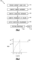
- Figure 2 provides a general overview of the usage-based scheduling system for determining when manual inspections and maintenance are required to identify and repair foreign object damage for a given engine in a gas turbine engine, such as the engine 10 illustrated in figure 1 .
- the aircraft data recorder is connected to a computer, and the flight data is provided to an analysis system in a "Provide Aircraft Usage Data" step 110.
- the aircraft usage data includes engine metrics measured by conventional engine sensors, such as those described above.
- one engine metric that can be used is rotor speed which infers exposure to vibrational modes which can also be correlated to various types of foreign object damage or debris ingestion events.
- the total stress state defined by the combination of active vibrational modes and foreign object damage which acts as a stress riser, is determined throughout a time history.
- the stress time history is then used to calculate a damage increment.
- usage data is applied to a set of models to compute the expected damage increment for the specific flight in a "Compute Damage Increment" step 120.
- the expected damage increment is calculated using a probabilistic foreign object damage model at least partially dependent on and continuously calibrated to, statistical data sets of previous inspection and usage data and assuming that foreign object damage has occurred for each flight and at each potential foreign object damage zone of the component.
- the expected damage increment is calculated at each mode of vibration that is excited in the engine by measuring or computing the time history of the response.
- the foreign object damage model is an engineering model.
- the damage is summed for contributing modes of vibration to determine the damage increment for the specific flight.
- the engineering model for foreign object damage is manually revised based on empirical results in the field to account for new inspection and usage data. This update can be performed manually, automatically, or both, depending on the type of inspection and usage data acquired.
- the system applies the increment to the damage history of the engine in a "Compute Cumulative Damage" step 130.
- the cumulative damage represents the total deterioration over time of the engine components since the previous maintenance. In a practical example there are a large number of cumulative damage values that are independently tracked, and the complexity resulting from the amount of tracked values would take longer to calculate manually than there is time between flights and the process could not be practicably achieved without computer assistance.
- the probability of failure of the components in a subsequent flight is determined in a "Compute Probability of Failure" step 140.
- the probability of failure is calculated for each possible foreign object damage location from each flight that has occurred since the previous maintenance. This process is repeated for each airfoil or airfoil type separately, and in the aggregate, as well as for any other components that are susceptible to foreign object damage.
- any components, such as blades include unique information or attributes
- each of the components that have unique information is analyzed independently to account for the special information.
- an assembly such as a bladed wheel includes, as a whole, a defining feature such as intentional mistuning, the components of the assembly driving the defining feature are analyzed in the aggregate.
- the system 100 When the probability of failure on the next flight (alternately referred to as "risk") exceeds a predefined threshold, the system 100 outputs an inspection requirement in an "Output Inspection Requirement" step 150.
- the risk threshold is in the range of 1/100000 to 1/10000, although specific implementations may stray from that range depending on the particular usage of the engine and aircraft in question, as well as the applicable industry or internal standards.
- the probability of failure is below the risk threshold an inspection is not ordered, and the process is reiterated after the next flight.
- Figure 3 illustrates an example cycle over 5 sequential flights.
- the cumulative risk increases until the fourth flight, where the cumulative risk exceeds the predefined threshold 142.
- the computer system operating the process orders an inspection and maintenance is performed.
- the computer system assumes 100% effective inspection and maintenance and causes the cumulative risk to be reset to no cumulative risk prior the fifth flight.
- the reset can account for "imperfect" maintenance by resetting to a cumulative damage value above zero.
- the system can wait for a confirmation that the maintenance operation was successful before resetting the cumulative risk.
- each damage increment is dependent on the total aircraft usage data from the corresponding flight, the number of flights or the number of flight hours between maintenance is not uniform, and the occurrence of costly and time-consuming manual inspections and maintenance is limited to times when the risk of foreign object damage exceeds an acceptable level.
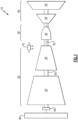
- Figure 4 schematically illustrates an exemplary model computer system 200 for implementing the process 100 of Figure 1 including both physical components and software modules.
- the computer system 200 includes a flight data recorder 210 connected to the computer system 200 either via a physical data transfer connection 212 or via a wireless, or similar, data transfer connection.
- the aircraft usage data is provided to foreign object damage module 220 that computes the damage increment from the given flight based on the aircraft usage data, and a set of correlation models 222 including a material capability model 224, a vibratory response characterization model 226, and any other models 228 able to determine expected magnitudes of foreign object damage based on the aircraft usage data.
- a rate, severity, and location assessment module 221 that uses the models 222 to determine the expected rate, severity, and location of foreign object damage.
- the models 222 are combined with inlet debris monitoring system readings and the exhaust distress monitoring systems data from the aircraft usage data to determine the expected rate severity, and location of foreign object damage.
- the data storage component 230 can be any form of data storage, and can be located internal to the computer system 200, internal to the flight data recorder 210 storing the aircraft usage data, or external to both systems.
- the incremental damage that is calculated is passed to a cumulative damage module 240.
- the cumulative damage module 240 retrieves the stored historical damage increments from the data storage element 230 and generates the total cumulative damage, which is then provided to a risk calculation module 250.
- the risk calculation module 250 determines the probability of failure based on the total cumulative damage, as described above, and compares the probability of failure to the acceptable risk. When the probability exceeds the acceptable risk, the computer system provides an alert at an output system 260 that informs the technician that a manual inspection is required.
- a fatigue damage accumulation rule such as Miner's Rule
- the material capability model determines "cycles to failure" using a stress-life modeling system. In other examples, alternative modeling systems can be utilized to similar effect. Most time points have negligible damage levels of zero or approximately zero, however every time point is summed regardless of whether the damage level is approximately zero or is substantial.
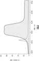
- Figure 5 illustrates the damage increments for one zone at two modes of vibration according to an exemplary Goodman analysis model. As can be seen the illustrated two modes include spikes, or plateaus, where the damage levels are meaningful but are still primarily filled with de minimus damage levels.
- a standard stress-life model defines the distribution for cycles to failure at all stress levels.
- Standard stress-life models are used to relate the logarithm of life to stress or the logarithm of stress.
- scatter in life is quantified using standard distributions such as the lognormal, Weibull, or smallest extreme value.
- Model forms, as well as specific values for numeric constants are determined from specimen and/or component fatigue testing.
- Figures 6-8 illustrate an exemplary process for determining an aggregate risk ( Figure 8 ) based on the cumulative damage ( Figure 6 ).
- each flight produces the same damage increment (i.e., 0.05), with the set of lines in Figure 6 corresponding to a first FOD occurring on flight 1 ( D 1, j ,1 ), a first FOD occurs on flight 2 ( D 2,j,1 ), ..., and a first FOD occurs on flight 26 ( D 26, j ,1 ).
- Each cumulative damage sum line from Figure 6 has an associated conditional probability of failure curve. In a practical example, the increment will not be identical between flights.
- Figure 7 illustrates the conditional probabilities of failure based on the first FOD occurring on flight 1 ( p 1, j ), the first FOD occurring on flight 2 ( p 2, j ), ... and the first FOD occurring on flight 26 ( p 26 , j ).
- each curve asymptotically approaches 1, as the failure is an eventual certainty.
- the risk curves across all 26 flights from Figure 7 are aggregated into a single risk curve, illustrated in Figure 8 .
- Total Risk at Flight j Prob(HCF @ Flight j
- the aggregated risk is the value that is compared with the acceptable risk to determine whether an inspection and maintenance is required after each flight.
- the usage based maintenance scheduling reduces maintenance cost and increase fleet readiness by replacing traditional schedule based inspection with the above described process that predicts the need for inspection based on engine usage.
Landscapes
- Engineering & Computer Science (AREA)
- Physics & Mathematics (AREA)
- General Physics & Mathematics (AREA)
- Combustion & Propulsion (AREA)
- Chemical & Material Sciences (AREA)
- Theoretical Computer Science (AREA)
- General Engineering & Computer Science (AREA)
- Business, Economics & Management (AREA)
- Human Resources & Organizations (AREA)
- Computer Hardware Design (AREA)
- Geometry (AREA)
- Evolutionary Computation (AREA)
- Mechanical Engineering (AREA)
- Operations Research (AREA)
- Entrepreneurship & Innovation (AREA)
- Marketing (AREA)
- Economics (AREA)
- Quality & Reliability (AREA)
- Strategic Management (AREA)
- Tourism & Hospitality (AREA)
- General Business, Economics & Management (AREA)
- Automation & Control Theory (AREA)
- Testing Of Devices, Machine Parts, Or Other Structures Thereof (AREA)
- Management, Administration, Business Operations System, And Electronic Commerce (AREA)
Abstract
Description
- The present disclosure relates generally to maintenance scheduling for aircraft engines, and more particularly to a scheduling system based on the actual usage of the aircraft engine.
- Traditional maintenance scheduling for aircraft engines includes a combination of life expectancy and observational scheduling, with the life expectancy scheduling being predetermined based on an expected use case and the structure of the component, and the observational being based on routine and periodic observation of specific components to identify damage.
- Observational scheduling generally includes high frequency maintenance intended to prevent failure in components prone to Foreign Object Damage (FOD). Observational scheduling assumes a worst-case scenario of engine operation and FOD when defining inspection frequency and damage limits. Due to the worst-case scenario assumptions, observed FOD can lead to immediate unscheduled maintenance that may not be required to prevent component failure.
- Predetermined, or life expectancy based, maintenance schedules are generally low frequency, primarily intended to prevent failure in components from damage incurred during an assumed engine operation, which may be conservative, e.g., aggressive use in harsh environments with more FOD assumed than experience might dictate.
- In scheduling both life expectancy and observational based maintenance, assumptions are made in-terms of both the stress-state from vibration modes and stress increase due to FOD exposure and severity. These assumptions can result in increased fleet sustainment cost through unnecessary inspection and repair operations.
- From one aspect, there is provided a process for scheduling engine inspection for a gas turbine engine that includes computing an expected damage increment based on aircraft usage data of a single flight, computing a cumulative expected damage by summing the expected damage increment with a total set of historical expected damage increments since a previous maintenance, determining an aggregate risk of failure based on the computed cumulative expected damage, and signaling a manual inspection in response to the aggregate risk of failure exceeding an acceptable risk threshold.
- In another example of the above described process for scheduling engine inspection for a gas turbine engine the acceptable risk threshold is in the range of 1/100000 to 1/10000.
- Another example of any of the above described processes for scheduling engine inspection for a gas turbine engine further includes resetting the total set of historical expected damage increments since a previous maintenance in response to a manual inspection occurring.
- In another example of any of the above described processes for scheduling engine inspection for a gas turbine engine the aircraft usage data omits foreign object strike detection.
- In another example of any of the above described processes for scheduling engine inspection for a gas turbine engine computing the expected damage increment comprises using a probabilistic foreign object damage model defined at least in part by previous inspection and usage data.
- In another example of any of the above described processes for scheduling engine inspection for a gas turbine engine the probabilistic foreign object damage model is manually updated in response to new inspection and usage data.
- In another example of any of the above described processes for scheduling engine inspection for a gas turbine engine the probabilistic foreign object damage model is at least partially dependent on a statistical data set.
- In another example of any of the above described processes for scheduling engine inspection for a gas turbine engine the probabilistic foreign object damage model is automatically updated in response to new inspection and usage data.
- In another example of any of the above described processes for scheduling engine inspection for a gas turbine engine resetting the total set of historical expected damage increments since a previous maintenance comprises setting the total set of historical expected damage increments to zero.
- In another example of any of the above described processes for scheduling engine inspection for a gas turbine engine computing the expected damage increment comprises determining an expected damage increment at each mode of vibration that is excited in the engine, and summing the increment over all modes to determine the expected damage increment for a specific flight.
- In another example of any of the above described processes for scheduling engine inspection for a gas turbine engine computing the expected damage increment comprises applying the aircraft usage data to a set of correlation models.
- In another example of any of the above described processes for scheduling engine inspection for a gas turbine engine the set of correlation models includes at least a material capability model and a vibratory response characterization model.
- Another example of any of the above described processes for scheduling engine inspection for a gas turbine engine further includes reiterating the process for each blade of at least one stage of the gas turbine engine.
- There is also provided a computer system for determining maintenance schedules for a gas turbine engine includes a foreign object damage module configured to determine an incremental foreign object damage based on data from an aircraft flight recorder, a data storage component configured to store historical incremental foreign object damage, a cumulative damage module configured to sum the determined incremental foreign object damage and the historical foreign object damage, and a risk determination module configured to determine an aggregate risk of foreign object damage based on the determined cumulative damage.
- Another example of the above described computer system for determining maintenance schedules for a gas turbine engine further includes a connection for receiving a physical data transfer from an aircraft flight recorder.
- Another example of any of the above described computer systems for determining maintenance schedules for a gas turbine engine further includes a wireless receiver configured to receive a wireless data transfer from an aircraft flight recorder.
- In another example of any of the above described computer system for determining maintenance schedules for a gas turbine engine the foreign object damage module includes rate severity and location estimator configured to estimate at least one of a rate, severity and location of expected foreign object damage based on the data from the aircraft flight recorder.
- In another example of any of the above described computer system for determining maintenance schedules for a gas turbine engine the foreign object damage module includes at least a material capability model and a vibratory response characterization model.
- Another example of any of the above described computer system for determining maintenance schedules for a gas turbine engine further includes an output module configured to output an inspection required signal in response to a risk from the risk aggregation module exceeding a predefined threshold.
- In another example of any of the above described computer system for determining maintenance schedules for a gas turbine engine the predefined threshold is in the range of 1/100000 to 1/10000.
- These and other features of the present invention can be best understood from the following specification and drawings, the following of which is a brief description.
-
-
Figure 1 schematically illustrates a gas turbine engine according to one example. -
Figure 2 illustrates a high level exemplary process for implementing a usage based maintenance scheduling system. -
Figure 3 illustrates an example operation of the process ofFigure 2 over time. -
Figure 4 schematically illustrates a flow model of a computer system for implementing the process ofFigure 1 . -
Figure 5 illustrates an example fatigue assessment of the damage calculation. -
Figure 6 illustrates a cumulative damage over flights of an example aircraft. -
Figure 7 illustrates specific risk curves corresponding to the cumulative damages ofFigure 6 . -
Figure 8 illustrates the aggregate risk curve of all of the risk curves ofFigure 7 . -
Figure 1 illustrates an exemplarygas turbine engine 10, including acompressor section 20 connected to acombustor section 30 and aturbine section 40 via afirst shaft 50 and asecond shaft 52. The exemplary compressor section includes alow pressure compressor 22 fluidly connected to ahigh pressure compressor 24. An output of thehigh pressure compressor 24 is provided to at least onecombustor 32 within thecombustor section 30. The at least onecombustor 32 mixes the output of thehigh pressure compressor 24 with a fuel and combusts the mixture. The resultant combustion products are provided to ahigh pressure turbine 44 along the flowpath. The high pressure turbine expands the combustion products which drives rotation of the high pressure turbine and thesecond shaft 52. Similarly, the output of thehigh pressure turbine 44 is provided to alow pressure turbine 42 and expanded. The expansion across thelow pressure turbine 42 drives rotation of thelow pressure turbine 42 and rotation of thefirst shaft 50. Thesecond shaft 52 is connected to thehigh pressure compressor 24 and drives rotation of thehigh pressure compressor 24. Similarly, thefirst shaft 50 is connected to, and drives rotation of thelow pressure compressor 22. Afan 60 is disposed upstream of thelow pressure compressor 22 and is driven to rotate via a gearedconnection 62 to thefirst shaft 50. In alternate examples, thefan 60 can be connected via a direct drive, omitting the gearedconnection 62. - The
gas turbine engine 10 described above, and illustrated inFigure 1 is exemplary in nature, and it is appreciated that the following systems and processes can be applied similarly to any other aircraft engine, even when the other engine deviates substantially from the generally described construction. Due to the design and operating environment of theengine 10, certain components such as fan blades and compressor blades are subject to damage from debris and other ingested objects. The damage is referred to as foreign object damage (FOD). - During operation of the
gas turbine engine 10, adata recorder 70 that is either local to the engine 10 (as in the example ofFigure 1 ), or within the aircraft and connected to sensors within the engine, stores flight operational data including, but not limited to rotor speed, time history, total engine flight hours, engine flight hours at maximum operating conditions, pressure and temperature at 1 or more engine station, aircraft altitude and mach number or forward velocity, crosswind speed, direction and any similar metrics. Flight operational data is at least partially determined via onboard sensors according to any known sensor configuration. Additional flight operational data can be inferred from one or more sensors according to known correlations and/or derived at least partially from engine control signals throughout the flight. After the flight, the data recorder is physically removed from the aircraft and provided to a computer system for analysis. In alternative examples, the aircraft can be physically connected to the computer system upon landing via a communication connection, or the data recorder can communicate wirelessly with the land-based computer system. In yet further alternative designs, a computer or controller onboard the aircraft can perform the process described below. - Rather than following a predefined time or flight hours-based maintenance and inspection schedule, the system described herein applies usage data from the flight data recorder to determine a probability of damage or risk of component failure ("risk"). Risk is then used to order maintenance as needed. This is referred to herein as "usage-based scheduling". Usage-based scheduling offers reduced maintenance frequency by accounting for actual engine use to reduce or eliminate conservative assumptions that are necessary to define an observational or predetermined maintenance schedule.
-
Figure 2 provides a general overview of the usage-based scheduling system for determining when manual inspections and maintenance are required to identify and repair foreign object damage for a given engine in a gas turbine engine, such as theengine 10 illustrated infigure 1 . After each flight the aircraft data recorder is connected to a computer, and the flight data is provided to an analysis system in a "Provide Aircraft Usage Data"step 110. - The aircraft usage data includes engine metrics measured by conventional engine sensors, such as those described above. By way of example, one engine metric that can be used is rotor speed which infers exposure to vibrational modes which can also be correlated to various types of foreign object damage or debris ingestion events. The total stress state, defined by the combination of active vibrational modes and foreign object damage which acts as a stress riser, is determined throughout a time history. The stress time history is then used to calculate a damage increment. In practice, usage data is applied to a set of models to compute the expected damage increment for the specific flight in a "Compute Damage Increment"
step 120. The expected damage increment is calculated using a probabilistic foreign object damage model at least partially dependent on and continuously calibrated to, statistical data sets of previous inspection and usage data and assuming that foreign object damage has occurred for each flight and at each potential foreign object damage zone of the component. In examples using vibrational modes to correlate with occurrences of foreign object damage and/or debris ingestion, the expected damage increment is calculated at each mode of vibration that is excited in the engine by measuring or computing the time history of the response. In some examples, the foreign object damage model is an engineering model. - The damage is summed for contributing modes of vibration to determine the damage increment for the specific flight. In some examples, after a certain number of iterations, the engineering model for foreign object damage is manually revised based on empirical results in the field to account for new inspection and usage data. This update can be performed manually, automatically, or both, depending on the type of inspection and usage data acquired.
- Once the expected damage increment has been calculated, the system applies the increment to the damage history of the engine in a "Compute Cumulative Damage"
step 130. The cumulative damage represents the total deterioration over time of the engine components since the previous maintenance. In a practical example there are a large number of cumulative damage values that are independently tracked, and the complexity resulting from the amount of tracked values would take longer to calculate manually than there is time between flights and the process could not be practicably achieved without computer assistance. - After determining the cumulative damage values, the probability of failure of the components in a subsequent flight is determined in a "Compute Probability of Failure"
step 140. The probability of failure is calculated for each possible foreign object damage location from each flight that has occurred since the previous maintenance. This process is repeated for each airfoil or airfoil type separately, and in the aggregate, as well as for any other components that are susceptible to foreign object damage. By way of example, if any components, such as blades include unique information or attributes, each of the components that have unique information is analyzed independently to account for the special information. Alternatively, when an assembly such as a bladed wheel includes, as a whole, a defining feature such as intentional mistuning, the components of the assembly driving the defining feature are analyzed in the aggregate. - When the probability of failure on the next flight (alternately referred to as "risk") exceeds a predefined threshold, the
system 100 outputs an inspection requirement in an "Output Inspection Requirement"step 150. In one example, the risk threshold is in the range of 1/100000 to 1/10000, although specific implementations may stray from that range depending on the particular usage of the engine and aircraft in question, as well as the applicable industry or internal standards. When the probability of failure is below the risk threshold an inspection is not ordered, and the process is reiterated after the next flight. - When an inspection is ordered, manual inspection and maintenance is performed on the aircraft during which any damage, including foreign object damage, is manually identified and repaired by one or more technician in a "Perform Maintenance"
step 160. Once any identified damage is repaired, or the corresponding components are replaced, the historical record of damage data is reset to 0 in a "Reset"step 170, and theprocess 100 reiterates with the next flight. - With continued reference to the
process 100 ofFigure 2, Figure 3 illustrates an example cycle over 5 sequential flights. After each flight, the cumulative risk (RISK) increases until the fourth flight, where the cumulative risk exceeds thepredefined threshold 142. After the fourth flight, the computer system operating the process orders an inspection and maintenance is performed. In one example, the computer system assumes 100% effective inspection and maintenance and causes the cumulative risk to be reset to no cumulative risk prior the fifth flight. In other examples, the reset can account for "imperfect" maintenance by resetting to a cumulative damage value above zero. In yet further examples, the system can wait for a confirmation that the maintenance operation was successful before resetting the cumulative risk. As each damage increment is dependent on the total aircraft usage data from the corresponding flight, the number of flights or the number of flight hours between maintenance is not uniform, and the occurrence of costly and time-consuming manual inspections and maintenance is limited to times when the risk of foreign object damage exceeds an acceptable level. - With continued reference to
Figures 1-3 ,Figure 4 schematically illustrates an exemplarymodel computer system 200 for implementing theprocess 100 ofFigure 1 including both physical components and software modules. Thecomputer system 200 includes aflight data recorder 210 connected to thecomputer system 200 either via a physicaldata transfer connection 212 or via a wireless, or similar, data transfer connection. The aircraft usage data is provided to foreignobject damage module 220 that computes the damage increment from the given flight based on the aircraft usage data, and a set ofcorrelation models 222 including amaterial capability model 224, a vibratoryresponse characterization model 226, and anyother models 228 able to determine expected magnitudes of foreign object damage based on the aircraft usage data. Also included in the foreignobject damage module 220 is a rate, severity, andlocation assessment module 221 that uses themodels 222 to determine the expected rate, severity, and location of foreign object damage. In some examples, themodels 222 are combined with inlet debris monitoring system readings and the exhaust distress monitoring systems data from the aircraft usage data to determine the expected rate severity, and location of foreign object damage. - Summed foreign object damage across all contributing modes of vibration that are generated by the foreign
object damage module 220 is stored within adata storage component 230 during each iteration, creating a set of historical damage calculations. Thedata storage component 230 can be any form of data storage, and can be located internal to thecomputer system 200, internal to theflight data recorder 210 storing the aircraft usage data, or external to both systems. - In addition to the
data storage element 230, the incremental damage that is calculated is passed to acumulative damage module 240. Thecumulative damage module 240 retrieves the stored historical damage increments from thedata storage element 230 and generates the total cumulative damage, which is then provided to arisk calculation module 250. Therisk calculation module 250 determines the probability of failure based on the total cumulative damage, as described above, and compares the probability of failure to the acceptable risk. When the probability exceeds the acceptable risk, the computer system provides an alert at anoutput system 260 that informs the technician that a manual inspection is required. - To determine the damage increment based on the material capability of the blades, a fatigue damage accumulation rule, such as Miner's Rule, is applied at each time point of a predetermined frequency and the time points are summed for each mode. In the Miner's rule example, the damage at a given time point i is defined as:

Figure 5 illustrates the damage increments for one zone at two modes of vibration according to an exemplary Goodman analysis model. As can be seen the illustrated two modes include spikes, or plateaus, where the damage levels are meaningful but are still primarily filled with de minimus damage levels. - In addition to Goodman modeling, a standard stress-life model defines the distribution for cycles to failure at all stress levels. Standard stress-life models are used to relate the logarithm of life to stress or the logarithm of stress. Similarly, scatter in life is quantified using standard distributions such as the lognormal, Weibull, or smallest extreme value. Model forms, as well as specific values for numeric constants are determined from specimen and/or component fatigue testing.
- With continued reference to
Figures 1-4 ,Figures 6-8 illustrate an exemplary process for determining an aggregate risk (Figure 8 ) based on the cumulative damage (Figure 6 ). For the sake of explanation, in the example ofFigure 6 , each flight produces the same damage increment (i.e., 0.05), with the set of lines inFigure 6 corresponding to a first FOD occurring on flight 1 (D 1,j,1), a first FOD occurs on flight 2 (D2,j,1 ), ..., and a first FOD occurs on flight 26 (D 26,j,1). Each cumulative damage sum line fromFigure 6 has an associated conditional probability of failure curve. In a practical example, the increment will not be identical between flights. -
Figure 7 illustrates the conditional probabilities of failure based on the first FOD occurring on flight 1 (p 1,j ), the first FOD occurring on flight 2 (p 2,j ), ... and the first FOD occurring on flight 26 (p 26, j ). As can be seen, each curve asymptotically approaches 1, as the failure is an eventual certainty. As the process is performed without determining or sensing actual foreign object damage occurrences it is unknown when, or if, the foreign object damage occurs. Thus, the risk curves across all 26 flights fromFigure 7 are aggregated into a single risk curve, illustrated inFigure 8 . The risk is aggregated using the standard rules of probability: Total Risk at Flight j = Prob(HCF @ Flight j | FOD on 1) × Prob(FOD on 1) + Prob( HCF @ Flight j | FOD on 2) × Prob(FOD on 2) + ···+ Prob( HCF @ Flight j | FOD on j) × Prob(FOD on j). - The aggregated risk is the value that is compared with the acceptable risk to determine whether an inspection and maintenance is required after each flight.
- By using the above described process and system, the usage based maintenance scheduling reduces maintenance cost and increase fleet readiness by replacing traditional schedule based inspection with the above described process that predicts the need for inspection based on engine usage.
- It is further understood that any of the above described concepts can be used alone or in combination with any or all of the other above described concepts. Although an embodiment of this invention has been disclosed, a worker of ordinary skill in this art would recognize that certain modifications would come within the scope of this invention. For that reason, the following claims should be studied to determine the true scope and content of this invention.
Claims (15)
- A process for scheduling engine inspection for a gas turbine engine (10) comprising:computing an expected damage increment based on aircraft usage data of a single flight;computing a cumulative expected damage by summing the expected damage increment with a total set of historical expected damage increments since a previous maintenance;determining an aggregate risk of failure based on the computed cumulative expected damage; andsignaling a manual inspection in response to the aggregate risk of failure exceeding an acceptable risk threshold (142).
- The process of claim 1, wherein the acceptable risk threshold (142) is in the range of 1/100000 to 1/10000.
- The process of claim 1 or 2, further comprising resetting the total set of historical expected damage increments since a previous maintenance in response to a manual inspection occurring, wherein, resetting the total set of historical expected damage increments since a previous maintenance optionally comprises setting the total set of historical expected damage increments to zero.
- The process of any preceding claim, wherein the aircraft usage data omits foreign object strike detection.
- The process of any preceding claim, wherein computing the expected damage increment comprises using a probabilistic foreign object damage model (220) defined at least in part by previous inspection and usage data.
- The process of claim 5, wherein the probabilistic foreign object damage model (220) is manually updated in response to new inspection and usage data.
- The process of claim 5, wherein the probabilistic foreign object damage model (220) is at least partially dependent on a statistical data set, wherein, optionally, the probabilistic foreign object damage model (220) is automatically updated in response to new inspection and usage data.
- The process of any preceding claim, wherein computing the expected damage increment comprises determining an expected damage increment at each mode of vibration that is excited in the engine, and summing the increment over all modes to determine the expected damage increment for a specific flight.
- The process of any preceding claim, wherein computing the expected damage increment comprises applying the aircraft usage data to a set of correlation models (222), wherein the set of correlation models (222) optionally includes at least a material capability model (224) and a vibratory response characterization model (226).
- The process of any preceding claim, further comprising reiterating the process for each blade of at least one stage (60, 22, 24, 44, 42) of the gas turbine engine (10).
- A computer system (200) for determining maintenance schedules for a gas turbine engine (10) comprising:a foreign object damage module (220) configured to determine an incremental foreign object damage based on data from an aircraft flight recorder (210);a data storage component (230) configured to store historical incremental foreign object damage;a cumulative damage module (240) configured to sum the determined incremental foreign object damage and the historical foreign object damage; anda risk determination module (250) configured to determine an aggregate risk of foreign object damage based on the determined cumulative damage.
- The computer system (200) of claim 11, further comprising a connection (212) for receiving a physical data transfer from the aircraft flight recorder (210), or further comprising a wireless receiver configured to receive a wireless data transfer from the aircraft flight recorder (210).
- The computer system (200) of claim 11 or 12, wherein the foreign object damage module (220) includes rate severity and location estimator (221) configured to estimate at least one of a rate, severity and location of expected foreign object damage based on the data from the aircraft flight recorder (210).
- The computer system (200) of any of claims 11 to 13, wherein the foreign object damage module (220) includes at least a material capability model (224) and a vibratory response characterization model (226).
- The computer system (200) of any of claims 11 to 14, further comprising an output module (260) configured to output an inspection required signal in response to a risk from the risk determination module (250) exceeding a predefined threshold (142), wherein the predefined threshold (142) is optionally in the range of 1/100000 to 1/10000.
Applications Claiming Priority (2)
| Application Number | Priority Date | Filing Date | Title |
|---|---|---|---|
| US202163227392P | 2021-07-30 | 2021-07-30 | |
| US17/464,837 US20230036153A1 (en) | 2021-07-30 | 2021-09-02 | Usage based maintenance scheduling system |
Publications (2)
| Publication Number | Publication Date |
|---|---|
| EP4124921A1 true EP4124921A1 (en) | 2023-02-01 |
| EP4124921B1 EP4124921B1 (en) | 2025-08-27 |
Family
ID=83228583
Family Applications (1)
| Application Number | Title | Priority Date | Filing Date |
|---|---|---|---|
| EP22186481.2A Active EP4124921B1 (en) | 2021-07-30 | 2022-07-22 | Usage based maintenance scheduling system |
Country Status (2)
| Country | Link |
|---|---|
| US (2) | US20230036153A1 (en) |
| EP (1) | EP4124921B1 (en) |
Cited By (1)
| Publication number | Priority date | Publication date | Assignee | Title |
|---|---|---|---|---|
| CN119991050A (en) * | 2025-04-15 | 2025-05-13 | 广东海洋大学 | An automated sports equipment management system and method |
Citations (3)
| Publication number | Priority date | Publication date | Assignee | Title |
|---|---|---|---|---|
| US20180328221A1 (en) * | 2017-05-09 | 2018-11-15 | United Technologies Corporation | System and method for planning engine borescope inspections based on fod probability estimation |
| EP3736778A1 (en) * | 2019-05-08 | 2020-11-11 | The Boeing Company | Predictive part maintenance |
| US20200356958A1 (en) * | 2019-05-08 | 2020-11-12 | Honeywell International Inc. | Usage-based maintenance system for vehicles and method of operating the same |
Family Cites Families (3)
| Publication number | Priority date | Publication date | Assignee | Title |
|---|---|---|---|---|
| US9841756B2 (en) * | 2015-05-27 | 2017-12-12 | Siemens Energy, Inc. | Scheduling inspections and predicting end-of-life for machine components |
| US11334854B2 (en) * | 2017-11-10 | 2022-05-17 | General Electric Company | Systems and methods to generate an asset workscope |
| US10964130B1 (en) * | 2018-10-18 | 2021-03-30 | Northrop Grumman Systems Corporation | Fleet level prognostics for improved maintenance of vehicles |
-
2021
- 2021-09-02 US US17/464,837 patent/US20230036153A1/en not_active Abandoned
-
2022
- 2022-07-22 EP EP22186481.2A patent/EP4124921B1/en active Active
-
2025
- 2025-10-27 US US19/370,376 patent/US20260049899A1/en active Pending
Patent Citations (3)
| Publication number | Priority date | Publication date | Assignee | Title |
|---|---|---|---|---|
| US20180328221A1 (en) * | 2017-05-09 | 2018-11-15 | United Technologies Corporation | System and method for planning engine borescope inspections based on fod probability estimation |
| EP3736778A1 (en) * | 2019-05-08 | 2020-11-11 | The Boeing Company | Predictive part maintenance |
| US20200356958A1 (en) * | 2019-05-08 | 2020-11-12 | Honeywell International Inc. | Usage-based maintenance system for vehicles and method of operating the same |
Cited By (1)
| Publication number | Priority date | Publication date | Assignee | Title |
|---|---|---|---|---|
| CN119991050A (en) * | 2025-04-15 | 2025-05-13 | 广东海洋大学 | An automated sports equipment management system and method |
Also Published As
| Publication number | Publication date |
|---|---|
| US20230036153A1 (en) | 2023-02-02 |
| US20260049899A1 (en) | 2026-02-19 |
| EP4124921B1 (en) | 2025-08-27 |
Similar Documents
| Publication | Publication Date | Title |
|---|---|---|
| US20260049899A1 (en) | Usage based maintenance scheduling system | |
| JP5844978B2 (en) | System and method for monitoring a gas turbine | |
| KR101529762B1 (en) | Method for detecting whether performance of aircraft components is in the decline period | |
| US9317249B2 (en) | Operations support systems and methods for calculating and evaluating turbine temperatures and health | |
| US8321118B2 (en) | Operations support systems and methods with power assurance | |
| US20130024179A1 (en) | Model-based approach for personalized equipment degradation forecasting | |
| US7328128B2 (en) | Method, system, and computer program product for performing prognosis and asset management services | |
| US20090048730A1 (en) | Method and system for planning repair of an engine | |
| US10042964B2 (en) | Method of evaluating a part | |
| US20040088100A1 (en) | Method for performing gas turbine performance diagnostics | |
| US20030074171A1 (en) | Adaptive aero-thermodynamic engine model | |
| EP2390742B1 (en) | Monitoring engine usage | |
| US20100138132A1 (en) | Engine health monitoring | |
| Volponi | Gas turbine engine health management: past, present and future trends | |
| EP1927039A1 (en) | Monitoring a system having degrading components | |
| US11396823B2 (en) | System and method for monitoring temperature of a gas turbine engine | |
| US20130238256A1 (en) | Method and system to model risk of unplanned outages of power generation machine | |
| US10400624B2 (en) | System and method for planning engine borescope inspections based on FOD probability estimation | |
| CN107667280A (en) | The scheduling inspection of machine part and bimetry terminate | |
| EP3742359B1 (en) | Systems and methods for auxiliary power unit health indicator computation | |
| Marinai et al. | Detection and prediction of the performance deterioration of a turbofan engine | |
| EP4227516B1 (en) | Use of particulate sensor in engine power assurance | |
| US20250139318A1 (en) | System and Method for Turbine Engine Parameter Synthesis | |
| Borguet et al. | Assessment of an anomaly detector for jet engine health monitoring | |
| UA156377U (en) | THE METHOD OF DIAGNOSING AN AVIATION DOUBLE-CIRCUIT GAS TURBINE ENGINE ACCORDING TO THE WORKING PROCESS PARAMETERS THAT ARE REGISTERED IN OPERATION |
Legal Events
| Date | Code | Title | Description |
|---|---|---|---|
| PUAI | Public reference made under article 153(3) epc to a published international application that has entered the european phase |
Free format text: ORIGINAL CODE: 0009012 |
|
| STAA | Information on the status of an ep patent application or granted ep patent |
Free format text: STATUS: THE APPLICATION HAS BEEN PUBLISHED |
|
| AK | Designated contracting states |
Kind code of ref document: A1 Designated state(s): AL AT BE BG CH CY CZ DE DK EE ES FI FR GB GR HR HU IE IS IT LI LT LU LV MC MK MT NL NO PL PT RO RS SE SI SK SM TR |
|
| STAA | Information on the status of an ep patent application or granted ep patent |
Free format text: STATUS: REQUEST FOR EXAMINATION WAS MADE |
|
| 17P | Request for examination filed |
Effective date: 20230719 |
|
| RBV | Designated contracting states (corrected) |
Designated state(s): AL AT BE BG CH CY CZ DE DK EE ES FI FR GB GR HR HU IE IS IT LI LT LU LV MC MK MT NL NO PL PT RO RS SE SI SK SM TR |
|
| RAP3 | Party data changed (applicant data changed or rights of an application transferred) |
Owner name: RTX CORPORATION |
|
| STAA | Information on the status of an ep patent application or granted ep patent |
Free format text: STATUS: EXAMINATION IS IN PROGRESS |
|
| 17Q | First examination report despatched |
Effective date: 20240103 |
|
| GRAP | Despatch of communication of intention to grant a patent |
Free format text: ORIGINAL CODE: EPIDOSNIGR1 |
|
| STAA | Information on the status of an ep patent application or granted ep patent |
Free format text: STATUS: GRANT OF PATENT IS INTENDED |
|
| RIC1 | Information provided on ipc code assigned before grant |
Ipc: G07C 5/00 20060101ALI20250314BHEP Ipc: G06Q 10/20 20230101ALI20250314BHEP Ipc: G05B 23/02 20060101AFI20250314BHEP |
|
| INTG | Intention to grant announced |
Effective date: 20250407 |
|
| GRAS | Grant fee paid |
Free format text: ORIGINAL CODE: EPIDOSNIGR3 |
|
| GRAA | (expected) grant |
Free format text: ORIGINAL CODE: 0009210 |
|
| STAA | Information on the status of an ep patent application or granted ep patent |
Free format text: STATUS: THE PATENT HAS BEEN GRANTED |
|
| AK | Designated contracting states |
Kind code of ref document: B1 Designated state(s): AL AT BE BG CH CY CZ DE DK EE ES FI FR GB GR HR HU IE IS IT LI LT LU LV MC MK MT NL NO PL PT RO RS SE SI SK SM TR |
|
| REG | Reference to a national code |
Ref country code: CH Ref legal event code: EP |
|
| REG | Reference to a national code |
Ref country code: DE Ref legal event code: R096 Ref document number: 602022020113 Country of ref document: DE |
|
| REG | Reference to a national code |
Ref country code: IE Ref legal event code: FG4D |
|
| REG | Reference to a national code |
Ref country code: NL Ref legal event code: MP Effective date: 20250827 |
|
| PG25 | Lapsed in a contracting state [announced via postgrant information from national office to epo] |
Ref country code: IS Free format text: LAPSE BECAUSE OF FAILURE TO SUBMIT A TRANSLATION OF THE DESCRIPTION OR TO PAY THE FEE WITHIN THE PRESCRIBED TIME-LIMIT Effective date: 20251227 |
|
| PG25 | Lapsed in a contracting state [announced via postgrant information from national office to epo] |
Ref country code: NO Free format text: LAPSE BECAUSE OF FAILURE TO SUBMIT A TRANSLATION OF THE DESCRIPTION OR TO PAY THE FEE WITHIN THE PRESCRIBED TIME-LIMIT Effective date: 20251127 |
|
| REG | Reference to a national code |
Ref country code: LT Ref legal event code: MG9D |
|
| PG25 | Lapsed in a contracting state [announced via postgrant information from national office to epo] |
Ref country code: PT Free format text: LAPSE BECAUSE OF FAILURE TO SUBMIT A TRANSLATION OF THE DESCRIPTION OR TO PAY THE FEE WITHIN THE PRESCRIBED TIME-LIMIT Effective date: 20251229 |
|
| PG25 | Lapsed in a contracting state [announced via postgrant information from national office to epo] |
Ref country code: FI Free format text: LAPSE BECAUSE OF FAILURE TO SUBMIT A TRANSLATION OF THE DESCRIPTION OR TO PAY THE FEE WITHIN THE PRESCRIBED TIME-LIMIT Effective date: 20250827 |
|
| PG25 | Lapsed in a contracting state [announced via postgrant information from national office to epo] |
Ref country code: HR Free format text: LAPSE BECAUSE OF FAILURE TO SUBMIT A TRANSLATION OF THE DESCRIPTION OR TO PAY THE FEE WITHIN THE PRESCRIBED TIME-LIMIT Effective date: 20250827 Ref country code: NL Free format text: LAPSE BECAUSE OF FAILURE TO SUBMIT A TRANSLATION OF THE DESCRIPTION OR TO PAY THE FEE WITHIN THE PRESCRIBED TIME-LIMIT Effective date: 20250827 |
|
| PG25 | Lapsed in a contracting state [announced via postgrant information from national office to epo] |
Ref country code: GR Free format text: LAPSE BECAUSE OF FAILURE TO SUBMIT A TRANSLATION OF THE DESCRIPTION OR TO PAY THE FEE WITHIN THE PRESCRIBED TIME-LIMIT Effective date: 20251128 |
|
| PG25 | Lapsed in a contracting state [announced via postgrant information from national office to epo] |
Ref country code: SE Free format text: LAPSE BECAUSE OF FAILURE TO SUBMIT A TRANSLATION OF THE DESCRIPTION OR TO PAY THE FEE WITHIN THE PRESCRIBED TIME-LIMIT Effective date: 20250827 |
|
| PG25 | Lapsed in a contracting state [announced via postgrant information from national office to epo] |
Ref country code: LV Free format text: LAPSE BECAUSE OF FAILURE TO SUBMIT A TRANSLATION OF THE DESCRIPTION OR TO PAY THE FEE WITHIN THE PRESCRIBED TIME-LIMIT Effective date: 20250827 |
|
| PG25 | Lapsed in a contracting state [announced via postgrant information from national office to epo] |
Ref country code: PL Free format text: LAPSE BECAUSE OF FAILURE TO SUBMIT A TRANSLATION OF THE DESCRIPTION OR TO PAY THE FEE WITHIN THE PRESCRIBED TIME-LIMIT Effective date: 20250827 Ref country code: BG Free format text: LAPSE BECAUSE OF FAILURE TO SUBMIT A TRANSLATION OF THE DESCRIPTION OR TO PAY THE FEE WITHIN THE PRESCRIBED TIME-LIMIT Effective date: 20250827 |
|
| PG25 | Lapsed in a contracting state [announced via postgrant information from national office to epo] |
Ref country code: RS Free format text: LAPSE BECAUSE OF FAILURE TO SUBMIT A TRANSLATION OF THE DESCRIPTION OR TO PAY THE FEE WITHIN THE PRESCRIBED TIME-LIMIT Effective date: 20251127 |
|
| PG25 | Lapsed in a contracting state [announced via postgrant information from national office to epo] |
Ref country code: ES Free format text: LAPSE BECAUSE OF FAILURE TO SUBMIT A TRANSLATION OF THE DESCRIPTION OR TO PAY THE FEE WITHIN THE PRESCRIBED TIME-LIMIT Effective date: 20250827 |
|
| REG | Reference to a national code |
Ref country code: AT Ref legal event code: MK05 Ref document number: 1830651 Country of ref document: AT Kind code of ref document: T Effective date: 20250827 |
|
| PG25 | Lapsed in a contracting state [announced via postgrant information from national office to epo] |
Ref country code: SM Free format text: LAPSE BECAUSE OF FAILURE TO SUBMIT A TRANSLATION OF THE DESCRIPTION OR TO PAY THE FEE WITHIN THE PRESCRIBED TIME-LIMIT Effective date: 20250827 |
|
| PG25 | Lapsed in a contracting state [announced via postgrant information from national office to epo] |
Ref country code: DK Free format text: LAPSE BECAUSE OF FAILURE TO SUBMIT A TRANSLATION OF THE DESCRIPTION OR TO PAY THE FEE WITHIN THE PRESCRIBED TIME-LIMIT Effective date: 20250827 |
|
| PG25 | Lapsed in a contracting state [announced via postgrant information from national office to epo] |
Ref country code: AT Free format text: LAPSE BECAUSE OF FAILURE TO SUBMIT A TRANSLATION OF THE DESCRIPTION OR TO PAY THE FEE WITHIN THE PRESCRIBED TIME-LIMIT Effective date: 20250827 |
|
| PG25 | Lapsed in a contracting state [announced via postgrant information from national office to epo] |
Ref country code: IT Free format text: LAPSE BECAUSE OF FAILURE TO SUBMIT A TRANSLATION OF THE DESCRIPTION OR TO PAY THE FEE WITHIN THE PRESCRIBED TIME-LIMIT Effective date: 20250827 |
|
| PG25 | Lapsed in a contracting state [announced via postgrant information from national office to epo] |
Ref country code: CZ Free format text: LAPSE BECAUSE OF FAILURE TO SUBMIT A TRANSLATION OF THE DESCRIPTION OR TO PAY THE FEE WITHIN THE PRESCRIBED TIME-LIMIT Effective date: 20250827 |
|
| PG25 | Lapsed in a contracting state [announced via postgrant information from national office to epo] |
Ref country code: SK Free format text: LAPSE BECAUSE OF FAILURE TO SUBMIT A TRANSLATION OF THE DESCRIPTION OR TO PAY THE FEE WITHIN THE PRESCRIBED TIME-LIMIT Effective date: 20250827 Ref country code: EE Free format text: LAPSE BECAUSE OF FAILURE TO SUBMIT A TRANSLATION OF THE DESCRIPTION OR TO PAY THE FEE WITHIN THE PRESCRIBED TIME-LIMIT Effective date: 20250827 |