EP4124889A1 - A method and a system to detect a junction ahead of a vehicle - Google Patents
A method and a system to detect a junction ahead of a vehicle Download PDFInfo
- Publication number
- EP4124889A1 EP4124889A1 EP22187357.3A EP22187357A EP4124889A1 EP 4124889 A1 EP4124889 A1 EP 4124889A1 EP 22187357 A EP22187357 A EP 22187357A EP 4124889 A1 EP4124889 A1 EP 4124889A1
- Authority
- EP
- European Patent Office
- Prior art keywords
- junction
- vehicle
- road boundary
- processors
- cells
- Prior art date
- Legal status (The legal status is an assumption and is not a legal conclusion. Google has not performed a legal analysis and makes no representation as to the accuracy of the status listed.)
- Pending
Links
Images


Classifications
-
- G—PHYSICS
- G06—COMPUTING OR CALCULATING; COUNTING
- G06V—IMAGE OR VIDEO RECOGNITION OR UNDERSTANDING
- G06V20/00—Scenes; Scene-specific elements
- G06V20/50—Context or environment of the image
- G06V20/56—Context or environment of the image exterior to a vehicle by using sensors mounted on the vehicle
- G06V20/588—Recognition of the road, e.g. of lane markings; Recognition of the vehicle driving pattern in relation to the road
-
- B—PERFORMING OPERATIONS; TRANSPORTING
- B60—VEHICLES IN GENERAL
- B60W—CONJOINT CONTROL OF VEHICLE SUB-UNITS OF DIFFERENT TYPE OR DIFFERENT FUNCTION; CONTROL SYSTEMS SPECIALLY ADAPTED FOR HYBRID VEHICLES; ROAD VEHICLE DRIVE CONTROL SYSTEMS FOR PURPOSES NOT RELATED TO THE CONTROL OF A PARTICULAR SUB-UNIT
- B60W30/00—Purposes of road vehicle drive control systems not related to the control of a particular sub-unit, e.g. of systems using conjoint control of vehicle sub-units
- B60W30/18—Propelling the vehicle
- B60W30/18009—Propelling the vehicle related to particular drive situations
- B60W30/18154—Approaching an intersection
-
- B—PERFORMING OPERATIONS; TRANSPORTING
- B60—VEHICLES IN GENERAL
- B60W—CONJOINT CONTROL OF VEHICLE SUB-UNITS OF DIFFERENT TYPE OR DIFFERENT FUNCTION; CONTROL SYSTEMS SPECIALLY ADAPTED FOR HYBRID VEHICLES; ROAD VEHICLE DRIVE CONTROL SYSTEMS FOR PURPOSES NOT RELATED TO THE CONTROL OF A PARTICULAR SUB-UNIT
- B60W30/00—Purposes of road vehicle drive control systems not related to the control of a particular sub-unit, e.g. of systems using conjoint control of vehicle sub-units
- B60W30/18—Propelling the vehicle
- B60W30/18009—Propelling the vehicle related to particular drive situations
- B60W30/18159—Traversing an intersection
-
- G—PHYSICS
- G06—COMPUTING OR CALCULATING; COUNTING
- G06V—IMAGE OR VIDEO RECOGNITION OR UNDERSTANDING
- G06V10/00—Arrangements for image or video recognition or understanding
- G06V10/40—Extraction of image or video features
- G06V10/42—Global feature extraction by analysis of the whole pattern, e.g. using frequency domain transformations or autocorrelation
- G06V10/422—Global feature extraction by analysis of the whole pattern, e.g. using frequency domain transformations or autocorrelation for representing the structure of the pattern or shape of an object therefor
-
- B—PERFORMING OPERATIONS; TRANSPORTING
- B60—VEHICLES IN GENERAL
- B60W—CONJOINT CONTROL OF VEHICLE SUB-UNITS OF DIFFERENT TYPE OR DIFFERENT FUNCTION; CONTROL SYSTEMS SPECIALLY ADAPTED FOR HYBRID VEHICLES; ROAD VEHICLE DRIVE CONTROL SYSTEMS FOR PURPOSES NOT RELATED TO THE CONTROL OF A PARTICULAR SUB-UNIT
- B60W2552/00—Input parameters relating to infrastructure
- B60W2552/53—Road markings, e.g. lane marker or crosswalk
-
- G—PHYSICS
- G01—MEASURING; TESTING
- G01S—RADIO DIRECTION-FINDING; RADIO NAVIGATION; DETERMINING DISTANCE OR VELOCITY BY USE OF RADIO WAVES; LOCATING OR PRESENCE-DETECTING BY USE OF THE REFLECTION OR RERADIATION OF RADIO WAVES; ANALOGOUS ARRANGEMENTS USING OTHER WAVES
- G01S13/00—Systems using the reflection or reradiation of radio waves, e.g. radar systems; Analogous systems using reflection or reradiation of waves whose nature or wavelength is irrelevant or unspecified
- G01S13/88—Radar or analogous systems specially adapted for specific applications
- G01S13/93—Radar or analogous systems specially adapted for specific applications for anti-collision purposes
- G01S13/931—Radar or analogous systems specially adapted for specific applications for anti-collision purposes of land vehicles
Definitions
- the present disclosure generally relates to the field of autonomous vehicles. More particularly, the present disclosure relates to a method and a system to detect a junction ahead of a vehicle.
- Autonomous vehicle technology is progressing from needing driver assistance to having full autonomy.
- the autonomous vehicle technology is enabling the real-time decision-making of humans in autonomous vehicles.
- Navigation of the autonomous vehicles is performed by receiving road information.
- the road information supports the autonomous vehicles when performing driving manoeuvres.
- the capability of recognizing road junctions and handling subsequent decisions is essential for autonomous vehicles.
- GPS Global Positioning System
- the present disclosure discloses a method to detect a junction ahead of a vehicle.
- the method comprises determining a first road boundary to a left side of a vehicle and a second road boundary to a right side of the vehicle. Further, the method comprises determining a first direction associated with the first road boundary and a second direction associated with the second road boundary in a direction of movement of the vehicle. Furthermore, the method comprises identifying presence of a junction ahead of the vehicle based on the determined first and second directions. Thereafter, the method comprises determining a pattern associated with the junction. The pattern is determined to detect the junction as one of, a roundabout or an angular intersection ahead of the vehicle.
- the present disclosure discloses a detection system to detect a junction ahead of a vehicle.
- the detection system comprises one or more processors and a memory.
- the one or more processors are configured to determine a first road boundary to a left side of a vehicle and a second road boundary to a right side of the vehicle. Further, the one or more processors are configured to determine a first direction associated with the first road boundary and a second direction associated with the second road boundary in a direction of movement of the vehicle. Furthermore, the one or more processors are configured to identify presence of a junction ahead of the vehicle based on the determined first and second directions. Thereafter, the one or more processors are configured to determine a pattern associated with the junction. The pattern is determined to detect the junction as one of, a roundabout or an angular intersection ahead of the vehicle.
- road boundary means a boundary between a road and a site or a surface not configured or designed for motor vehicles to travel on.
- junction is where more than two roads meet.
- the junction may be the roundabout, the angular intersection, and the like.
- angular intersection is a junction where at least two roads meet and movement of vehicles in multiple directions is controlled using a traffic signal.
- the angular intersection is a T-junction, a Y-junction, and the like.
- An angular intersection does not comprise a central island or a surface not configured or designed for motor vehicles to travel on around which a continuous movement of vehicles is permitted.
- roundabout is a junction where at least two roads meet, and continuous movement of vehicles is permitted in one direction around a central island or a surface not configured or designed for motor vehicles to travel on.
- vehicle means a transportation device suitable for transporting humans or goods from a first location to a second location.
- first road boundary means a boundary to a left side of the vehicle.
- second road boundary means a boundary to a right side of the vehicle.
- pattern means a shape, size and the like of the junction.
- the term "at least” followed by a number is used in to denote the start of a range beginning with that number (which may be a range having an upper limit or no upper limit, depending on the variable being defined).
- “at least one” means one or more than one.
- any block diagram herein represents conceptual views of illustrative systems embodying the principles of the present subject matter.
- any flow charts, flow diagrams, state transition diagrams, pseudo code, and the like represent various processes which may be substantially represented in computer readable medium and executed by a computer or processor, whether or not such computer or processor is explicitly shown.
- Embodiments of the present disclosure relate to a method to detect junction ahead of vehicles. Firstly, road boundaries to a left side of a vehicle and a right side of the vehicle are determined. Next, first and second directions associated with the first road boundary and the second road boundary,, respectively in a direction of movement of the vehicle is determined. The presence of the junction ahead of the vehicle is identified based on the first and second directions associated with the road boundaries. Upon determining the presence of the junction, a pattern associated with the junction is determined. The junction is detected to be either a roundabout or an angular intersection based on the determined pattern.
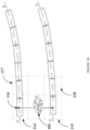
- FIG. 1A illustrates exemplary environment 100 to detect a junction ahead of a vehicle, in accordance with some embodiments of the present disclosure.
- the exemplary environment 100 comprises a vehicle 102, a first road boundary 103 to a left side of the vehicle 102 and a second road boundary 104 to a right side of the vehicle 102, and a junction 101 ahead of the vehicle 102.
- the vehicle 102 may be a car, a truck, a bus, and the like.
- the vehicle 102 may be an autonomous vehicle or a self-driving vehicle.
- the vehicle 102 may be embedded with Advanced Driver Assistance Systems (ADAS).
- ADAS Advanced Driver Assistance Systems
- the vehicle 102 may comprise a detection system 107.
- a person skilled in the art will appreciate that the vehicle 102 comprises several other components.
- the detection system 107 may be configured in an electronic control unit of the vehicle 102.
- the detection system 107 is configured to detect the junction 101 ahead of the vehicle 102.
- the junction 101 may be a roundabout, an angular intersection, and the like.
- the angular intersection may be a T-intersection.
- the detection system 107 may determine the first road boundary 103 and the second road boundary 104. Further, the detection system 107 may determine a first direction 105 associated with the first road boundary 103 and a second direction 106 associated with the second road boundary 104 in a direction of movement of the vehicle 102.
- the direction of movement of the vehicle is represented as 113.
- the first direction 105 associated with the first road boundary 103 may be away from the second direction 106 associated with the second road boundary 104 as shown in Figure 1 .
- the first and second directions 105, 106 may be bending away from each other, due to presence of the junction 101 ahead of the vehicle 102.
- the detection system 107 may determine the first and second directions 105, 106 associated with the first road boundary 103 and the second road boundary 104, respectively, in the direction 113 of movement of the vehicle 102, to identify the presence of the junction 101. Further, the detection system 107 may determine a pattern associated with the junction 101. The pattern may be determined to detect the junction 101 as one of, the roundabout or the angular intersection ahead of the vehicle 102.
- the detection system 107 may include Central Processing Units 108 (also referred as "CPUs” or “one or more processors 108"), Input/ Output (I/O) interface 109, and a memory 110.
- the memory 110 may be communicatively coupled to the processor 108.
- the memory 110 stores instructions executable by the one or more processors 108.
- the one or more processors 108 may comprise at least one data processor for executing program components for executing user or system-generated requests.
- the memory 110 may be communicatively coupled to the one or more processors 108.
- the memory 110 stores instructions, executable by the one or more processors 108, which, on execution, may cause the one or more processors 108 to detect the junction 101 ahead of the vehicle 102.
- the memory 110 may include one or more modules 112 and data 111.
- the one or more modules 112 may be configured to perform the steps of the present disclosure using the data 111, to detect junction 101 ahead of the vehicle 102.
- each of the one or more modules 112 may be implemented as a hardware unit which may be outside the memory 110 and coupled with the detection system 107.
- the term modules 112 refers to an Application Specific Integrated Circuit (ASIC), an electronic circuit, a Field-Programmable Gate Arrays (FPGA), Programmable System-on-Chip (PSoC), a combinational logic circuit, and/or other suitable components that provide described functionality.
- ASIC Application Specific Integrated Circuit
- FPGA Field-Programmable Gate Arrays
- PSoC Programmable System-on-Chip
- the one or more modules 112 when configured with the described functionality defined in the present disclosure will result in a novel hardware.
- the I/O interface 109 is coupled with the one or more processors 108 through which an input signal or/and an output signal is communicated.
- the detection system 107 may receive a grid map (grid map is explained in detail, later in the present description) to determine the first road boundary 103 and the second road boundary 104, via the I/O interface 109.
- the detection system 107 to detect the junction 101 ahead of the vehicle 102, may be implemented in a variety of computing systems, such as a laptop computer, a desktop computer, a Personal Computer (PC), a notebook, a smartphone, a tablet, e-book readers, a server, a network server, a cloud-based server and the like.
- FIG. 1B illustrates exemplary environment for determination of the first road boundary 103 and the second road boundary 104 based on the grid map.
- the grid map represents a map of an environment as an evenly spaced field of binary values, each representing the presence of an obstacle at a location in the environment.
- the grid map comprises a plurality of cells, with each cell comprising a value of occupancy in an environment surrounding the vehicle 102.
- the value of occupancy may be a probability for degree of occupancy on a location in the environment. For example, a high probability may indicate presence of an object or the obstacle at the location.
- the grid map may be generated from any suitable sensor, for example, a Radio Detection and Ranging (RADAR) sensor may be used.
- RADAR Radio Detection and Ranging
- the grid map may be used to determine the locations of the static obstacle.
- the value of occupancy may be a non-zero value for presence of the static obstacles.
- the value of occupancy may be 0 for free space.
- the first road boundary 103 and the second road boundary 104 may be static obstacles. Hence, a determination of the value of occupancy to be a non-zero value may help in determining the first road boundary 103 and the second road boundary 104. Initially, the value of occupancy of a first right cell 115 at a right side of the vehicle 102 may be determined to be a non-zero value. Similarly, the value of occupancy of a first left cell 114 at a left side of the vehicle 102 may be determined to be a non-zero value.
- the value may be non-zero at a location 116 in the environment. Further, the value of occupancy of one or more right cells 118 in a region ahead of the first right cell 115 is determined. Similarly, the value of occupancy of one or more left cells 117 in a region ahead of the first left cell 114 is determined. In the present description, the term one or more right cells 118 and one or more left cells 117 refer to successive cells ahead of the first right cell 115 and the first left cell 114, respectively. Further, the orientation of the one or more right cells 118 with respect to the first right cell 115 may be determined. Similarly, the orientation of the one or more left cells 117 with respect to the first left cell 114 may be determined.
- the first road boundary 103 and the second road boundary 104 are determined based on the determined value of occupancy and the orientation, of the one or more right cells 118 and the one or more left cells 117.
- the non-zero value of occupancy may be used to determine the presence of the first road boundary 103 and the second road boundary 104.
- the orientation may be used to determine only the presence of the first road boundary 103 and the second road boundary 104 and ignore other static obstacles such as poles.
- FIG. 2 illustrates an internal architecture 200 of the detection system 107 to detect the junction 101 ahead of the vehicle 102, in accordance with some embodiments of the present disclosure.
- the detection system 107 may include the one or more processors 108, the memory 110 and the I/O interface 109.
- the modules 112 may include, for example, a boundary determination module 206, a direction determination module 207, a junction identification module 208, a pattern determination module 209, and other modules 210. It will be appreciated that such aforementioned modules 112 may be represented as a single module or a combination of different modules.
- the data 111 may include, for example, boundary data 201, direction data 202, junction identification data 203, pattern data 204, and other data 205.
- the boundary determination module 206 may be configured to receive the grid map. In an embodiment, the boundary determination module 206 may receive the grid map from a sensor. In another embodiment, the grid map may be stored in the memory 110. The boundary determination module 206 may be configured to determine the value of occupancy of the first right cell 115 at the right side of the vehicle 102. Further, the boundary determination module 206 may be configured to determine the value of occupancy of the first left cell 114 at the left side of the vehicle 102. The boundary determination module 206 may determine the value of occupancy of each cell of the grid map, to the right side and the left cell of the vehicle 102. The boundary determination module 206 may ignore cells of the grid map with value of occupancy as zero.
- the boundary determination module 206 may consider a cell with the non-zero value, each at the right side and the left side of the vehicle 102, as the first right cell 115 and the first left cell 114, respectively. Further, the boundary determination module 206 may determine the value of occupancy of the one or more right cells 118 in a region ahead of the first right cell 115. Similarly, the boundary determination module 206 may determine the value of occupancy of the one or more left cells 117 in a region ahead of the first left cell 114. The boundary determination module 206 may determine the value of occupancy of the one or more right cells 118 and the one or more left cells 117 to determine a continuous boundary. The boundary determination module 206 may determine the value of occupancy for the static obstacles only.
- the boundary determination module 206 may determine an orientation of the one or more right cells 118 with respect to the first right cell 115. Similarly, the boundary determination module 206 may determine an orientation of the one or more left cells 117 with respect to the first left cell 114. The boundary determination module 206 may determine the orientation to determine a continuous boundary and ignore other static obstacles such as beacons. The boundary determination module 206 may determine the first road boundary 103 and the second road boundary 104 based on the determined value of occupancy and the orientation, of the one or more right cells 118 and the one or more left cells 117. The grid map, the value of occupancy of the first right cell 115, the first left cell 114, the one or more right cells 118, the one or more left cells 117 and corresponding orientations may be stored as the boundary data 201 in the memory 110.
- the direction determination module 207 may be configured to receive data related to the first road boundary 103 and the second road boundary 104 from the boundary determination module 206.
- the direction determination module 207 may determine the first direction 105 associated with the first road boundary 103 based on the orientation of the one or more right cells 118. Further, the direction determination module 207 may be configured to determine the second direction 106 associated with the second road boundary 104 based on the orientation of the one or more left cells 117.
- the first direction 105 associated with the first road boundary 103 and the second direction 106 associated with the second road boundary 104 may be determined in the direction 113 of movement of the vehicle 102.
- the determined first and second directions 105, 106 associated with the first road boundary 103 and the second road boundary 104, respectively, may be stored as the direction data 202 in the memory 110.
- the junction identification module 208 may be configured to receive the determined first and second directions 105, 106 associated with the first road boundary 103 and the second road boundary 104, respectively, from the direction determination module 207.
- the junction identification module 208 may determine the presence of the junction 101 ahead of the vehicle 102.
- the junction identification module 208 may determine an orientation of the first direction 105 associated with the first road boundary 103 with respect to an orientation of the second direction 106 associated with the second road boundary 104.
- the junction 101 ahead of the vehicle 102 When the first direction 105 associated with the first road boundary 103 is away from the second direction 106 associated with the second road boundary 104, there may the junction 101 ahead of the vehicle 102.
- the junction identification module 208 may determine the presence of the junction 101 when the first direction 105 associated with the first road boundary 103 is away from the second direction 106 associated with the second road boundary 104.
- Data related to the presence of the junction 101 may be stored as the junction identification data 203 in the memory 110, for further processing.
- the presence of the junction 101 may be stored as a value 1 along with a location of the junction 101.
- the locations of the junction 101 may be used for analysis.
- the pattern determination module 209 may be configured to receive the junction identification data 203.
- the pattern determination module 209 may receive a control signal from the junction identification module 208.
- the control signal may be having a value 1, indicating the presence of the junction 101 ahead of the vehicle 102.
- the pattern determination module 209 may determine a pattern associated with the junction 101.
- the pattern determination may comprise at least one of, detecting a shape of the junction 101 or an area occupied by the junction 101.
- the pattern determination module 209 may detect the shape of the junction 101 and the area occupied by the junction 101 based on the value of occupancy in the grid map.
- a person skilled in the art may appreciate the detection of the shape and the area of the junction 101 using edge detection, segmentation algorithms, and the like.
- the pattern determination module 209 may determine the junction 101 to be a roundabout when the shape of the junction 101 is a circular-like shape and the area occupied by the junction 101 is lesser than a first pre-determined threshold value.
- the circular-like shape may be a circle, an ellipse, or any circular like shape.
- the first pre-determined threshold value may be a minimum value to detect the junction 101 to be the roundabout.
- the pattern determination module 209 may determine the junction 101 to be an angular intersection when the junction 101 is formed by at least two roads, the shape of the junction 101 is such that each road of the at least two roads joining the junction 101 forms a pre-defined angle with each of other roads from the at least two roads, and the area occupied by the junction 101 is lesser than a second pre-determined threshold value.
- the angular junction may be a T-junction.
- the pre-defined angle between each road and other roads may be 90°.
- the angular junction may be a Y-junction.
- the pre-defined angle between a first road and each of a second road and a third road may be 135°.
- the pre-defined angle between the second road and the third road may be 90°.
- the second pre-determined threshold value may be a minimum value to detect the junction 101 to be the angular intersection.
- a plurality of pre-determined shapes associated with various junction types may be stored in the memory 110. The shape of the junction 101, the area occupied by the junction 101, the first pre-determined threshold value, and the second pre-determined threshold value may be stored as the pattern data 204 in the memory 110.
- the other data 205 may store data, including temporary data and temporary files, generated by the one or more modules 112 for performing the various functions of the detection system 107.
- the one or more modules 112 may also include the other modules 210 to perform various miscellaneous functionalities of the detection system 107.
- the other modules 210 may comprise a user interface to display a presence of the junction 101.
- the presence of the junction 101 may be provided as an alert.
- the presence of the junction 101 may be provided in any known forms.
- the presence of the junction 101 may be provided as text, voice, and the like.
- the alert may be stored as the other data 205 in the memory 110.
- the one or more modules 112 may be represented as a single module or a combination of different modules.
- Figure 3 shows an exemplary flow chart illustrating method steps to detect the junction 101 ahead of the vehicle 102, in accordance with some embodiments of the present disclosure.
- the method 300 may comprise one or more steps.
- the method 300 may be described in the general context of computer executable instructions.
- computer executable instructions can include routines, programs, objects, components, data structures, procedures, modules, and functions, which perform particular functions or implement particular abstract data types.
- the order in which the method 300 is described is not intended to be construed as a limitation, and any number of the described method blocks can be combined in any order to implement the method. Additionally, individual blocks may be deleted from the methods without departing from the scope of the subject matter described herein. Furthermore, the method can be implemented in any suitable hardware, software, firmware, or combination thereof.
- the first road boundary 103 to the left side of a vehicle 102 and the second road boundary 104 to the right side of the vehicle 102 may be determined by the detection system 107.
- the detection system 107 may receive the grid map. Further, the detection system 107 may determine the value of occupancy of the first right cell 115 at the right side of the vehicle 102 and the first left cell 114 at the left side of the vehicle 102, to be the non-zero value. Further, the detection system 107 may determine the value of occupancy of the one or more right cells 118 in a region ahead of the first right cell 115 and the one or more left cells 117 in a region ahead of the first left cell 114.
- the detection system 107 may determine an orientation of the one or more right cells 118 with respect to the first right cell 115. Similarly, the detection system 107 may determine an orientation of the one or more left cells 117 with respect to the first left cell 114. The detection system 107 may determine the first road boundary 103 and the second road boundary 104 based on the determined value of occupancy and the orientation, of the one or more right cells 118 and the one or more left cells 117. Referring to example 400 of Figure 4A , 401 shows the determination of the first road boundary 103 to the left side of the vehicle 102 based on the value of occupancy and the orientation of the one or more left cells 117. Similarly, 402 shows the determination of the second road boundary 104 to the right side of the vehicle 102 based on the value of occupancy and the orientation of the one or more right cells 118.
- the first direction 105 associated with the first road boundary 103 and the second direction 106 associated with the second road boundary 104 in the direction 113 of movement of the vehicle 102 is determined by the detection system 107.
- the detection system 107 may determine the first direction 105 associated with the first road boundary 103. Further, the detection system 107 may determine the second direction 106 associated with the second road boundary 104.
- the first direction 105 associated with the first road boundary 103 and the second direction 106 associated with the second road boundary 104 may be determined in the direction 113 of movement of the vehicle 102.
- the directions 105, 106 may be straight with respect to the direction 113 of movement of the vehicle 102.
- the directions 105, 106 may be at an angle with respect to the direction 113 of movement of the vehicle 102.
- the detection system 107 may determine an orientation of the first direction 105 associated with the first road boundary 103 with respect to the second direction 106 associated with the second road boundary 104.
- the detection system 107 may determine the presence of the junction 101 when the first direction 105 associated with the first road boundary 103 is away from the second direction 106 associated with the second road boundary 104. Referring back to the example 400 of Figure 4A , the first direction 105 associated with the first road boundary 103 is away from the second direction 106 associated with the second road boundary 104.
- the presence of the junction 101 ahead of the vehicle 102 may be determined.
- the pattern determination may comprise at least one of, detecting the shape of the junction 101 or the area occupied by the junction 101.
- the detection system 107 may detect the shape of the junction 101 and the area occupied by the junction 101 based on the value of occupancy in the grid map.
- the detection system 107 may determine the junction 101 to be the roundabout when the shape of the junction 101 is a circular-like shape and the area occupied by the junction 101 is lesser than the first pre-determined threshold value.
- the first pre-determined threshold value may be a minimum value to detect the junction 101 to be the roundabout.
- the detection system 107 may determine the junction 101 to be the angular intersection when the junction 101 is formed by at least two roads, the shape of the junction 101 is such that each road of the at least two roads joining the junction 101 forms a pre-defined angle with each of other roads from the at least two roads, and the area occupied by the junction 101 is lesser than a second pre-determined threshold value.
- the second pre-determined threshold value may be a minimum value to detect the junction 101 to be the angular intersection.
- the junction 101 may be a roundabout 404.
- the detection system 107 may determine the junction 101 to be the roundabout 404 based on the circular-like shape of the roundabout 404 and the area occupied by the roundabout 404.
- the detection system 107 may detect the shape of the roundabout 404 based on the value of occupancy of a plurality of cells 403 of the grid map.
- the detection system 107 may determine the first road boundary 103 and the second road boundary 104 based on the value of occupancy and the orientation of one or more left cells 501 and one or more right cells 502. There may be an angular intersection 504 ahead of the vehicle 102. The detection system 107 may determine the shape and the area occupied by the angular intersection 504. The detection system 107 may detect the shape of the angular intersection 504 based on the value of occupancy of a plurality of cells 503 of the grid map.
- FIG. 6 illustrates a block diagram of an exemplary computer system 600 for implementing embodiments consistent with the present disclosure.
- the computer system 600 may be used to implement the detection system 107.
- the computer system 600 may be used to detect the junction 101 ahead of the vehicle 612.
- the computer system 600 may comprise a Central Processing Unit 602 (also referred as "CPU” or "processor”).
- the processor 602 may comprise at least one data processor.
- the processor 602 may include specialized processing units such as integrated system (bus) controllers, memory management control units, floating point units, graphics processing units, digital signal processing units, etc.
- the processor 602 may be disposed in communication with one or more input/output (I/O) devices (not shown) via I/O interface 601.
- the I/O interface 601 may employ communication protocols/methods such as, without limitation, audio, analog, digital, monoaural, RCA, stereo, IEEE (Institute of Electrical and Electronics Engineers) -1394, serial bus, universal serial bus (USB), infrared, PS/2, BNC, coaxial, component, composite, digital visual interface (DVI), high-definition multimedia interface (HDMI), Radio Frequency (RF) antennas, S-Video, VGA, IEEE 802.n /b/g/n/x, Bluetooth, cellular (e.g., code-division multiple access (CDMA), high-speed packet access (HSPA+), global system for mobile communications (GSM), long-term evolution (LTE), WiMax, or the like), etc.
- CDMA code-division multiple access
- HSPA+ high-speed packet access
- GSM global system for mobile communications
- the computer system 600 may communicate with one or more I/O devices.
- the input device 610 may be an antenna, keyboard, mouse, joystick, (infrared) remote control, camera, card reader, fax machine, dongle, biometric reader, microphone, touch screen, touchpad, trackball, stylus, scanner, storage device, transceiver, video device/source, etc.
- the output device 611 may be a printer, fax machine, video display (e.g., cathode ray tube (CRT), liquid crystal display (LCD), light-emitting diode (LED), plasma, Plasma display panel (PDP), Organic light-emitting diode display (OLED) or the like), audio speaker, etc.
- CTR cathode ray tube
- LCD liquid crystal display
- LED light-emitting diode
- PDP Plasma display panel
- OLED Organic light-emitting diode display
- the computer system 600 may be connected to the vehicle 612 through a communication network 609.
- the processor 602 may be disposed in communication with the communication network 609 via a network interface 603.
- the network interface 603 may communicate with the communication network 609.
- the network interface 603 may employ connection protocols including, without limitation, direct connect, Ethernet (e.g., twisted pair 10/100/1000 Base T), transmission control protocol/internet protocol (TCP/IP), token ring, IEEE 802.11a/b/g/n/x, etc.
- the communication network 609 may include, without limitation, a direct interconnection, local area network (LAN), wide area network (WAN), wireless network (e.g., using Wireless Application Protocol), the Internet, etc.
- the network interface 603 may employ connection protocols include, but not limited to, direct connect, Ethernet (e.g., twisted pair 10/100/1000 Base T), transmission control protocol/internet protocol (TCP/IP), token ring, IEEE 802.11a/b/g/n/x, etc.
- connection protocols include, but not limited to, direct connect, Ethernet (e.g., twisted pair 10/100/1000 Base T), transmission control protocol/internet protocol (TCP/IP), token ring, IEEE 802.11a/b/g/n/x, etc.
- the communication network 609 includes, but is not limited to, a direct interconnection, an e-commerce network, a peer to peer (P2P) network, local area network (LAN), wide area network (WAN), wireless network (e.g., using Wireless Application Protocol), the Internet, Wi-Fi, and such.
- the first network and the second network may either be a dedicated network or a shared network, which represents an association of the different types of networks that use a variety of protocols, for example, Hypertext Transfer Protocol (HTTP), Transmission Control Protocol/Internet Protocol (TCP/IP), Wireless Application Protocol (WAP), etc., to communicate with each other.
- the first network and the second network may include a variety of network devices, including routers, bridges, servers, computing devices, storage devices, etc.
- the processor 602 may be disposed in communication with a memory 605 (e.g., RAM, ROM, etc. not shown in Figure 6 ) via a storage interface 604.
- the storage interface 604 may connect to memory 605 including, without limitation, memory drives, removable disc drives, etc., employing connection protocols such as serial advanced technology attachment (SATA), Integrated Drive Electronics (IDE), IEEE-1394, Universal Serial Bus (USB), fiber channel, Small Computer Systems Interface (SCSI), etc.
- the memory drives may further include a drum, magnetic disc drive, magneto-optical drive, optical drive, Redundant Array of Independent Discs (RAID), solid-state memory devices, solid-state drives, etc.
- the memory 605 may store a collection of program or database components, including, without limitation, user interface 606, an operating system 607, web browser 608 etc.
- computer system 600 may store user/application data, such as, the data, variables, records, etc., as described in this disclosure.
- databases may be implemented as fault-tolerant, relational, scalable, secure databases such as Oracle ® or Sybase ® .
- the operating system 607 may facilitate resource management and operation of the computer system 600.
- Examples of operating systems include, without limitation, APPLE MACINTOSH R OS X, UNIX R , UNIX-like system distributions (E.G., BERKELEY SOFTWARE DISTRIBUTION TM (BSD), FREEBSD TM , NETBSD TM , OPENBSD TM , etc.), LINUX DISTRIBUTIONS TM (E.G., RED HAT TM , UBUNTU TM , KUBUNTU TM , etc.), IBM TM OS/2, MICROSOFT TM WINDOWS TM (XP TM , VISTA TM /7/8, 10 etc.), APPLE R IOS TM , GOOGLE R ANDROID TM , BLACKBERRY R OS, or the like.
- the computer system 600 may implement the web browser 608 stored program component.
- the web browser 608 may be a hypertext viewing application, for example MICROSOFT R INTERNET EXPLORER TM , GOOGLE R CHROME TM0 , MOZILLA R FIREFOX TM , APPLE R SAFARI TM , etc.
- Secure web browsing may be provided using Secure Hypertext Transport Protocol (HTTPS), Secure Sockets Layer (SSL), Transport Layer Security (TLS), etc.
- Web browsers 608 may utilize facilities such as AJAX TM , DHTML TM , ADOBE R FLASH TM , JAVASCRIPT TM , JAVA TM , Application Programming Interfaces (APIs), etc.
- the computer system 600 may implement a mail server (not shown in Figure) stored program component.
- the mail server may be an Internet mail server such as Microsoft Exchange, or the like.
- the mail server may utilize facilities such as ASP TM , ACTIVEX TM , ANSI TM C++/C#, MICROSOFT R , NET TM , CGI SCRIPTS TM , JAVA TM , JAVASCRIPT TM , PERL TM , PHP TM , PYTHON TM , WEBOBJECTS TM , etc.
- the mail server may utilize communication protocols such as Internet Message Access Protocol (IMAP), Messaging Application Programming Interface (MAPI), MICROSOFT R exchange, Post Office Protocol (POP), Simple Mail Transfer Protocol (SMTP), or the like.
- IMAP Internet Message Access Protocol
- MAPI Messaging Application Programming Interface
- PMP Post Office Protocol
- SMTP Simple Mail Transfer Protocol
- the computer system 600 may implement a mail client stored program component.
- the mail client (not shown in Figure) may be a mail viewing application, such as APPLE R MAIL TM , MICROSOFT R ENTOURAGE TM , MICROSOFT R OUTLOOK TM , MOZILLA R THUNDERBIRD TM , etc.
- a computer-readable storage medium refers to any type of physical memory on which information or data readable by a processor may be stored.
- a computer-readable storage medium may store instructions for execution by one or more processors, including instructions for causing the processor(s) to perform steps or stages consistent with the embodiments described herein.
- the term "computer-readable medium" should be understood to include tangible items and exclude carrier waves and transient signals, i.e., be non-transitory.
- RAM Random Access Memory
- ROM Read-Only Memory
- volatile memory volatile memory
- non-volatile memory hard drives
- CD ROMs Compact Disc Read-Only Memory
- DVDs Digital Video Disc
- flash drives disks, and any other known physical storage media.
- Embodiments of the present disclosure provides methods to detect junction ahead of vehicles in the absence of lane marks, road marks, traffic sign information and the like. Roundabout and angular intersection detection helps in smooth and safe manoeuvring of assisted/ automated vehicles in such traffic situations. Embodiments of the present disclosure can be used to detect diversion of roads.
- an embodiment means “one or more (but not all) embodiments of the invention(s)" unless expressly specified otherwise.
- Referral Numerals Referral Number Description 100 Exemplary environment 101 Junction 102 Vehicle 103 First road boundary 104 Second road boundary 105 First direction 106 Second direction 107 Detection system 108 Processor 109 I/O interface 110 Memory 111 Data 112 Modules 113 Direction of movement of vehicle 114 First left cell 115 First right cell 116 Location 117 One or more left cells 118 One or more right cells 200 Internal architecture 201 Boundary data 202 Direction data 203 Junction identification data 204 Pattern data 205 Other data 206 Boundary determination module 207 Direction determination module 208 Junction identification module 209 Pattern determination module 210 Other modules 400 Example 401 Determination of first road boundary 402 Determination of second road boundary 403 Plurality of cells 404 Roundabout 500 Example 501 Determination of first road boundary 502
Landscapes
- Engineering & Computer Science (AREA)
- Physics & Mathematics (AREA)
- General Physics & Mathematics (AREA)
- Multimedia (AREA)
- Theoretical Computer Science (AREA)
- Automation & Control Theory (AREA)
- Transportation (AREA)
- Mechanical Engineering (AREA)
- Computer Vision & Pattern Recognition (AREA)
- Traffic Control Systems (AREA)
Abstract
Description
- The present disclosure generally relates to the field of autonomous vehicles. More particularly, the present disclosure relates to a method and a system to detect a junction ahead of a vehicle.
- Autonomous vehicle technology is progressing from needing driver assistance to having full autonomy. The autonomous vehicle technology is enabling the real-time decision-making of humans in autonomous vehicles. Navigation of the autonomous vehicles is performed by receiving road information. The road information supports the autonomous vehicles when performing driving manoeuvres. The capability of recognizing road junctions and handling subsequent decisions is essential for autonomous vehicles.
- Conventional techniques use Global Positioning System (GPS) to handle road junctions and its subsequent decisions. However, it is difficult to get GPS signals in some places in the urban environment which render the junction decision handling erroneous. Further, the conventional techniques depend on information such as lane marks, road marks, traffic sign information, and the like. However, such techniques may fail in absence of the information. Hence, there is need for an improved system to detect the road junctions in absence of such information.
- The information disclosed in this background of the disclosure section is only for enhancement of understanding of the general background of the invention and should not be taken as an acknowledgement or any form of suggestion that this information forms the prior art already known to a person skilled in the art.
- In an embodiment, the present disclosure discloses a method to detect a junction ahead of a vehicle. The method comprises determining a first road boundary to a left side of a vehicle and a second road boundary to a right side of the vehicle. Further, the method comprises determining a first direction associated with the first road boundary and a second direction associated with the second road boundary in a direction of movement of the vehicle. Furthermore, the method comprises identifying presence of a junction ahead of the vehicle based on the determined first and second directions. Thereafter, the method comprises determining a pattern associated with the junction. The pattern is determined to detect the junction as one of, a roundabout or an angular intersection ahead of the vehicle.
- In an embodiment, the present disclosure discloses a detection system to detect a junction ahead of a vehicle. The detection system comprises one or more processors and a memory. The one or more processors are configured to determine a first road boundary to a left side of a vehicle and a second road boundary to a right side of the vehicle. Further, the one or more processors are configured to determine a first direction associated with the first road boundary and a second direction associated with the second road boundary in a direction of movement of the vehicle. Furthermore, the one or more processors are configured to identify presence of a junction ahead of the vehicle based on the determined first and second directions. Thereafter, the one or more processors are configured to determine a pattern associated with the junction. The pattern is determined to detect the junction as one of, a roundabout or an angular intersection ahead of the vehicle.
- As used in this summary, in the description below, in the claims below, and in the accompanying drawings, the term "road boundary" means a boundary between a road and a site or a surface not configured or designed for motor vehicles to travel on.
- As used in this summary, in the description below, in the claims below, and in the accompanying drawings, the term "junction" is where more than two roads meet. The junction may be the roundabout, the angular intersection, and the like.
- As used in this summary, in the description below, in the claims below, and in the accompanying drawings, the term "angular intersection" is a junction where at least two roads meet and movement of vehicles in multiple directions is controlled using a traffic signal. For example, the angular intersection is a T-junction, a Y-junction, and the like. An angular intersection does not comprise a central island or a surface not configured or designed for motor vehicles to travel on around which a continuous movement of vehicles is permitted.
- As used in this summary, in the description below, in the claims below, and in the accompanying drawings, the term "roundabout" is a junction where at least two roads meet, and continuous movement of vehicles is permitted in one direction around a central island or a surface not configured or designed for motor vehicles to travel on.
- As used in this summary, in the description below, in the claims below, and in the accompanying drawings, the term "vehicle" means a transportation device suitable for transporting humans or goods from a first location to a second location.
- As used in this summary, in the description below, in the claims below, and in the accompanying drawings, the term "first road boundary" means a boundary to a left side of the vehicle.
- As used in this summary, in the description below, in the claims below, and in the accompanying drawings, the term "second road boundary" means a boundary to a right side of the vehicle.
- As used in this summary, in the description below, in the claims below, and in the accompanying drawings, the term "pattern" means a shape, size and the like of the junction.
- As used in this summary, in the description below, in the claims below, and in the accompanying drawings, the term "at least" followed by a number is used in to denote the start of a range beginning with that number (which may be a range having an upper limit or no upper limit, depending on the variable being defined). For example, "at least one" means one or more than one.
- The foregoing summary is illustrative only and is not intended to be in any way limiting. In addition to the illustrative aspects, embodiments, and features described above, further aspects, embodiments, and features will become apparent by reference to the drawings and the following detailed description.
- The novel features and characteristics of the disclosure are set forth in the appended claims. The disclosure itself, however, as well as a preferred mode of use, further objectives, and advantages thereof, will best be understood by reference to the following detailed description of an illustrative embodiment when read in conjunction with the accompanying figures. One or more embodiments are now described, by way of example only, with reference to the accompanying figures wherein like reference numerals represent like elements and in which:
-
Figure 1A illustrates exemplary environment to detect a junction ahead of a vehicle, in accordance with some embodiments of the present disclosure; -
Figure 1B illustrates exemplary environment for determination of a first road boundary and a second road boundary based on a grid map, in accordance with some embodiments of the present disclosure; -
Figure 2 illustrates an internal architecture of a detection system to detect a junction ahead of a vehicle, in accordance with some embodiments of the present disclosure; -
Figure 3 shows an exemplary flow chart illustrating method steps to detect a junction ahead of a vehicle, in accordance with some embodiments of the present disclosure; -
Figures 4A ,4B , and5 show exemplary illustrations to detect a junction ahead of a vehicle, in accordance with some embodiments of the present disclosure; and -
Figure 6 shows a block diagram of a general-purpose computing system to detect a junction ahead of a vehicle, in accordance with embodiments of the present disclosure. - It should be appreciated by those skilled in the art that any block diagram herein represents conceptual views of illustrative systems embodying the principles of the present subject matter. Similarly, it will be appreciated that any flow charts, flow diagrams, state transition diagrams, pseudo code, and the like represent various processes which may be substantially represented in computer readable medium and executed by a computer or processor, whether or not such computer or processor is explicitly shown.
- In the present document, the word "exemplary" is used herein to mean "serving as an example, instance, or illustration." Any embodiment or implementation of the present subject matter described herein as "exemplary" is not necessarily to be construed as preferred or advantageous over other embodiments.
- While the disclosure is susceptible to various modifications and alternative forms, specific embodiment thereof has been shown by way of example in the drawings and will be described in detail below. It should be understood, however that it is not intended to limit the disclosure to the particular forms disclosed, but on the contrary, the disclosure is to cover all modifications, equivalents, and alternatives falling within the scope of the disclosure.
- The terms "comprises", "comprising", or any other variations thereof, are intended to cover a non-exclusive inclusion, such that a setup, device or method that comprises a list of components or steps does not include only those components or steps but may include other components or steps not expressly listed or inherent to such setup or device or method. In other words, one or more elements in a system or apparatus proceeded by "comprises... a" does not, without more constraints, preclude the existence of other elements or additional elements in the system or apparatus.
- Embodiments of the present disclosure relate to a method to detect junction ahead of vehicles. Firstly, road boundaries to a left side of a vehicle and a right side of the vehicle are determined. Next, first and second directions associated with the first road boundary and the second road boundary,, respectively in a direction of movement of the vehicle is determined. The presence of the junction ahead of the vehicle is identified based on the first and second directions associated with the road boundaries. Upon determining the presence of the junction, a pattern associated with the junction is determined. The junction is detected to be either a roundabout or an angular intersection based on the determined pattern.
-
Figure 1A illustratesexemplary environment 100 to detect a junction ahead of a vehicle, in accordance with some embodiments of the present disclosure. Theexemplary environment 100 comprises avehicle 102, afirst road boundary 103 to a left side of thevehicle 102 and asecond road boundary 104 to a right side of thevehicle 102, and ajunction 101 ahead of thevehicle 102. Thevehicle 102 may be a car, a truck, a bus, and the like. In an embodiment of the present disclosure, thevehicle 102 may be an autonomous vehicle or a self-driving vehicle. Thevehicle 102 may be embedded with Advanced Driver Assistance Systems (ADAS). Thevehicle 102 may comprise adetection system 107. A person skilled in the art will appreciate that thevehicle 102 comprises several other components. However, the other components are not named as they do not fall under the scope of the present disclosure. Thedetection system 107 may be configured in an electronic control unit of thevehicle 102. Thedetection system 107 is configured to detect thejunction 101 ahead of thevehicle 102. Thejunction 101 may be a roundabout, an angular intersection, and the like. The angular intersection may be a T-intersection. A person skilled in the art will appreciate the junctions are not limited to aforementioned junctions. Thedetection system 107 may determine thefirst road boundary 103 and thesecond road boundary 104. Further, thedetection system 107 may determine afirst direction 105 associated with thefirst road boundary 103 and asecond direction 106 associated with thesecond road boundary 104 in a direction of movement of thevehicle 102. The direction of movement of the vehicle is represented as 113. Thefirst direction 105 associated with thefirst road boundary 103 may be away from thesecond direction 106 associated with thesecond road boundary 104 as shown inFigure 1 . The first andsecond directions junction 101 ahead of thevehicle 102. Hence, thedetection system 107 may determine the first andsecond directions first road boundary 103 and thesecond road boundary 104, respectively, in thedirection 113 of movement of thevehicle 102, to identify the presence of thejunction 101. Further, thedetection system 107 may determine a pattern associated with thejunction 101. The pattern may be determined to detect thejunction 101 as one of, the roundabout or the angular intersection ahead of thevehicle 102. - The
detection system 107 may include Central Processing Units 108 (also referred as "CPUs" or "one ormore processors 108"), Input/ Output (I/O)interface 109, and amemory 110. In some embodiments, thememory 110 may be communicatively coupled to theprocessor 108. Thememory 110 stores instructions executable by the one ormore processors 108. The one ormore processors 108 may comprise at least one data processor for executing program components for executing user or system-generated requests. Thememory 110 may be communicatively coupled to the one ormore processors 108. Thememory 110 stores instructions, executable by the one ormore processors 108, which, on execution, may cause the one ormore processors 108 to detect thejunction 101 ahead of thevehicle 102. In an embodiment, thememory 110 may include one ormore modules 112 anddata 111. The one ormore modules 112 may be configured to perform the steps of the present disclosure using thedata 111, to detectjunction 101 ahead of thevehicle 102. In an embodiment, each of the one ormore modules 112 may be implemented as a hardware unit which may be outside thememory 110 and coupled with thedetection system 107. As used herein, theterm modules 112 refers to an Application Specific Integrated Circuit (ASIC), an electronic circuit, a Field-Programmable Gate Arrays (FPGA), Programmable System-on-Chip (PSoC), a combinational logic circuit, and/or other suitable components that provide described functionality. The one ormore modules 112 when configured with the described functionality defined in the present disclosure will result in a novel hardware. Further, the I/O interface 109 is coupled with the one ormore processors 108 through which an input signal or/and an output signal is communicated. For example, thedetection system 107 may receive a grid map (grid map is explained in detail, later in the present description) to determine thefirst road boundary 103 and thesecond road boundary 104, via the I/O interface 109. In an embodiment, thedetection system 107, to detect thejunction 101 ahead of thevehicle 102, may be implemented in a variety of computing systems, such as a laptop computer, a desktop computer, a Personal Computer (PC), a notebook, a smartphone, a tablet, e-book readers, a server, a network server, a cloud-based server and the like. -
Figure 1B illustrates exemplary environment for determination of thefirst road boundary 103 and thesecond road boundary 104 based on the grid map. The grid map represents a map of an environment as an evenly spaced field of binary values, each representing the presence of an obstacle at a location in the environment. The grid map comprises a plurality of cells, with each cell comprising a value of occupancy in an environment surrounding thevehicle 102. The value of occupancy may be a probability for degree of occupancy on a location in the environment. For example, a high probability may indicate presence of an object or the obstacle at the location. The grid map may be generated from any suitable sensor, for example, a Radio Detection and Ranging (RADAR) sensor may be used. A person skilled in the art will appreciate any known methods to generate the grid map may be used. The grid map may be used to determine the locations of the static obstacle. The value of occupancy may be a non-zero value for presence of the static obstacles. The value of occupancy may be 0 for free space. Thefirst road boundary 103 and thesecond road boundary 104 may be static obstacles. Hence, a determination of the value of occupancy to be a non-zero value may help in determining thefirst road boundary 103 and thesecond road boundary 104. Initially, the value of occupancy of a firstright cell 115 at a right side of thevehicle 102 may be determined to be a non-zero value. Similarly, the value of occupancy of a firstleft cell 114 at a left side of thevehicle 102 may be determined to be a non-zero value. The value may be non-zero at alocation 116 in the environment. Further, the value of occupancy of one or moreright cells 118 in a region ahead of the firstright cell 115 is determined. Similarly, the value of occupancy of one or moreleft cells 117 in a region ahead of the firstleft cell 114 is determined. In the present description, the term one or moreright cells 118 and one or moreleft cells 117 refer to successive cells ahead of the firstright cell 115 and the firstleft cell 114, respectively. Further, the orientation of the one or moreright cells 118 with respect to the firstright cell 115 may be determined. Similarly, the orientation of the one or moreleft cells 117 with respect to the firstleft cell 114 may be determined. Thefirst road boundary 103 and thesecond road boundary 104 are determined based on the determined value of occupancy and the orientation, of the one or moreright cells 118 and the one or moreleft cells 117. The non-zero value of occupancy may be used to determine the presence of thefirst road boundary 103 and thesecond road boundary 104. The orientation may be used to determine only the presence of thefirst road boundary 103 and thesecond road boundary 104 and ignore other static obstacles such as poles. -
Figure 2 illustrates aninternal architecture 200 of thedetection system 107 to detect thejunction 101 ahead of thevehicle 102, in accordance with some embodiments of the present disclosure. Thedetection system 107 may include the one ormore processors 108, thememory 110 and the I/O interface 109. - In one implementation, the
modules 112 may include, for example, aboundary determination module 206, adirection determination module 207, ajunction identification module 208, apattern determination module 209, andother modules 210. It will be appreciated that suchaforementioned modules 112 may be represented as a single module or a combination of different modules. In one implementation, thedata 111 may include, for example,boundary data 201,direction data 202,junction identification data 203,pattern data 204, andother data 205. - In an embodiment, the
boundary determination module 206 may be configured to receive the grid map. In an embodiment, theboundary determination module 206 may receive the grid map from a sensor. In another embodiment, the grid map may be stored in thememory 110. Theboundary determination module 206 may be configured to determine the value of occupancy of the firstright cell 115 at the right side of thevehicle 102. Further, theboundary determination module 206 may be configured to determine the value of occupancy of the firstleft cell 114 at the left side of thevehicle 102. Theboundary determination module 206 may determine the value of occupancy of each cell of the grid map, to the right side and the left cell of thevehicle 102. Theboundary determination module 206 may ignore cells of the grid map with value of occupancy as zero. Theboundary determination module 206 may consider a cell with the non-zero value, each at the right side and the left side of thevehicle 102, as the firstright cell 115 and the firstleft cell 114, respectively. Further, theboundary determination module 206 may determine the value of occupancy of the one or moreright cells 118 in a region ahead of the firstright cell 115. Similarly, theboundary determination module 206 may determine the value of occupancy of the one or moreleft cells 117 in a region ahead of the firstleft cell 114. Theboundary determination module 206 may determine the value of occupancy of the one or moreright cells 118 and the one or moreleft cells 117 to determine a continuous boundary. Theboundary determination module 206 may determine the value of occupancy for the static obstacles only. Further, theboundary determination module 206 may determine an orientation of the one or moreright cells 118 with respect to the firstright cell 115. Similarly, theboundary determination module 206 may determine an orientation of the one or moreleft cells 117 with respect to the firstleft cell 114. Theboundary determination module 206 may determine the orientation to determine a continuous boundary and ignore other static obstacles such as beacons. Theboundary determination module 206 may determine thefirst road boundary 103 and thesecond road boundary 104 based on the determined value of occupancy and the orientation, of the one or moreright cells 118 and the one or moreleft cells 117. The grid map, the value of occupancy of the firstright cell 115, the firstleft cell 114, the one or moreright cells 118, the one or moreleft cells 117 and corresponding orientations may be stored as theboundary data 201 in thememory 110. - In an embodiment, the
direction determination module 207 may be configured to receive data related to thefirst road boundary 103 and thesecond road boundary 104 from theboundary determination module 206. Thedirection determination module 207 may determine thefirst direction 105 associated with thefirst road boundary 103 based on the orientation of the one or moreright cells 118. Further, thedirection determination module 207 may be configured to determine thesecond direction 106 associated with thesecond road boundary 104 based on the orientation of the one or moreleft cells 117. Thefirst direction 105 associated with thefirst road boundary 103 and thesecond direction 106 associated with thesecond road boundary 104 may be determined in thedirection 113 of movement of thevehicle 102. The determined first andsecond directions first road boundary 103 and thesecond road boundary 104, respectively, may be stored as thedirection data 202 in thememory 110. - In an embodiment, the
junction identification module 208 may be configured to receive the determined first andsecond directions first road boundary 103 and thesecond road boundary 104, respectively, from thedirection determination module 207. Thejunction identification module 208 may determine the presence of thejunction 101 ahead of thevehicle 102. Thejunction identification module 208 may determine an orientation of thefirst direction 105 associated with thefirst road boundary 103 with respect to an orientation of thesecond direction 106 associated with thesecond road boundary 104. When thefirst direction 105 associated with thefirst road boundary 103 is away from thesecond direction 106 associated with thesecond road boundary 104, there may thejunction 101 ahead of thevehicle 102. Hence, thejunction identification module 208 may determine the presence of thejunction 101 when thefirst direction 105 associated with thefirst road boundary 103 is away from thesecond direction 106 associated with thesecond road boundary 104. Data related to the presence of thejunction 101 may be stored as thejunction identification data 203 in thememory 110, for further processing. For example, the presence of thejunction 101 may be stored as a value 1 along with a location of thejunction 101. The locations of thejunction 101 may be used for analysis. - In an embodiment, the
pattern determination module 209 may be configured to receive thejunction identification data 203. For example, thepattern determination module 209 may receive a control signal from thejunction identification module 208. The control signal may be having a value 1, indicating the presence of thejunction 101 ahead of thevehicle 102. Thepattern determination module 209 may determine a pattern associated with thejunction 101. The pattern determination may comprise at least one of, detecting a shape of thejunction 101 or an area occupied by thejunction 101. Thepattern determination module 209 may detect the shape of thejunction 101 and the area occupied by thejunction 101 based on the value of occupancy in the grid map. A person skilled in the art may appreciate the detection of the shape and the area of thejunction 101 using edge detection, segmentation algorithms, and the like. Thepattern determination module 209 may determine thejunction 101 to be a roundabout when the shape of thejunction 101 is a circular-like shape and the area occupied by thejunction 101 is lesser than a first pre-determined threshold value. The circular-like shape may be a circle, an ellipse, or any circular like shape. The first pre-determined threshold value may be a minimum value to detect thejunction 101 to be the roundabout. Further, thepattern determination module 209 may determine thejunction 101 to be an angular intersection when thejunction 101 is formed by at least two roads, the shape of thejunction 101 is such that each road of the at least two roads joining thejunction 101 forms a pre-defined angle with each of other roads from the at least two roads, and the area occupied by thejunction 101 is lesser than a second pre-determined threshold value. For example, the angular junction may be a T-junction. The pre-defined angle between each road and other roads may be 90°. In another example, the angular junction may be a Y-junction. The pre-defined angle between a first road and each of a second road and a third road may be 135°. Further, the pre-defined angle between the second road and the third road may be 90°. The second pre-determined threshold value may be a minimum value to detect thejunction 101 to be the angular intersection. A plurality of pre-determined shapes associated with various junction types may be stored in thememory 110. The shape of thejunction 101, the area occupied by thejunction 101, the first pre-determined threshold value, and the second pre-determined threshold value may be stored as thepattern data 204 in thememory 110. - The
other data 205 may store data, including temporary data and temporary files, generated by the one ormore modules 112 for performing the various functions of thedetection system 107. The one ormore modules 112 may also include theother modules 210 to perform various miscellaneous functionalities of thedetection system 107. For example, theother modules 210 may comprise a user interface to display a presence of thejunction 101. The presence of thejunction 101 may be provided as an alert. A person skilled in the art will appreciate that the presence of thejunction 101 may be provided in any known forms. For example, the presence of thejunction 101 may be provided as text, voice, and the like. The alert may be stored as theother data 205 in thememory 110. It will be appreciated that the one ormore modules 112 may be represented as a single module or a combination of different modules. -
Figure 3 shows an exemplary flow chart illustrating method steps to detect thejunction 101 ahead of thevehicle 102, in accordance with some embodiments of the present disclosure. As illustrated inFigure 3 , themethod 300 may comprise one or more steps. Themethod 300 may be described in the general context of computer executable instructions. Generally, computer executable instructions can include routines, programs, objects, components, data structures, procedures, modules, and functions, which perform particular functions or implement particular abstract data types. - The order in which the
method 300 is described is not intended to be construed as a limitation, and any number of the described method blocks can be combined in any order to implement the method. Additionally, individual blocks may be deleted from the methods without departing from the scope of the subject matter described herein. Furthermore, the method can be implemented in any suitable hardware, software, firmware, or combination thereof. - At
step 301, thefirst road boundary 103 to the left side of avehicle 102 and thesecond road boundary 104 to the right side of thevehicle 102 may be determined by thedetection system 107. Thedetection system 107 may receive the grid map. Further, thedetection system 107 may determine the value of occupancy of the firstright cell 115 at the right side of thevehicle 102 and the firstleft cell 114 at the left side of thevehicle 102, to be the non-zero value. Further, thedetection system 107 may determine the value of occupancy of the one or moreright cells 118 in a region ahead of the firstright cell 115 and the one or moreleft cells 117 in a region ahead of the firstleft cell 114. Further, thedetection system 107 may determine an orientation of the one or moreright cells 118 with respect to the firstright cell 115. Similarly, thedetection system 107 may determine an orientation of the one or moreleft cells 117 with respect to the firstleft cell 114. Thedetection system 107 may determine thefirst road boundary 103 and thesecond road boundary 104 based on the determined value of occupancy and the orientation, of the one or moreright cells 118 and the one or moreleft cells 117. Referring to example 400 ofFigure 4A , 401 shows the determination of thefirst road boundary 103 to the left side of thevehicle 102 based on the value of occupancy and the orientation of the one or moreleft cells 117. Similarly, 402 shows the determination of thesecond road boundary 104 to the right side of thevehicle 102 based on the value of occupancy and the orientation of the one or moreright cells 118. - Referring again to
Figure 3 , atstep 302, thefirst direction 105 associated with thefirst road boundary 103 and thesecond direction 106 associated with thesecond road boundary 104 in thedirection 113 of movement of thevehicle 102 is determined by thedetection system 107. Thedetection system 107 may determine thefirst direction 105 associated with thefirst road boundary 103. Further, thedetection system 107 may determine thesecond direction 106 associated with thesecond road boundary 104. Thefirst direction 105 associated with thefirst road boundary 103 and thesecond direction 106 associated with thesecond road boundary 104 may be determined in thedirection 113 of movement of thevehicle 102. For example, thedirections direction 113 of movement of thevehicle 102. Thedirections direction 113 of movement of thevehicle 102. - At
step 303, identifying presence of thejunction 101 ahead of thevehicle 102 based on the determined first andsecond directions detection system 107. Thedetection system 107 may determine an orientation of thefirst direction 105 associated with thefirst road boundary 103 with respect to thesecond direction 106 associated with thesecond road boundary 104. When thedirection 105 associated with thefirst road boundary 103 is away from thedirection 106 associated with thesecond road boundary 104, there may thejunction 101 ahead of thevehicle 102. Thedetection system 107 may determine the presence of thejunction 101 when thefirst direction 105 associated with thefirst road boundary 103 is away from thesecond direction 106 associated with thesecond road boundary 104. Referring back to the example 400 ofFigure 4A , thefirst direction 105 associated with thefirst road boundary 103 is away from thesecond direction 106 associated with thesecond road boundary 104. The presence of thejunction 101 ahead of thevehicle 102 may be determined. - At
step 304, determining the pattern associated with thejunction 101, by thedetection system 107. The pattern determination may comprise at least one of, detecting the shape of thejunction 101 or the area occupied by thejunction 101. Thedetection system 107 may detect the shape of thejunction 101 and the area occupied by thejunction 101 based on the value of occupancy in the grid map. Thedetection system 107 may determine thejunction 101 to be the roundabout when the shape of thejunction 101 is a circular-like shape and the area occupied by thejunction 101 is lesser than the first pre-determined threshold value. The first pre-determined threshold value may be a minimum value to detect thejunction 101 to be the roundabout. Further, thedetection system 107 may determine thejunction 101 to be the angular intersection when thejunction 101 is formed by at least two roads, the shape of thejunction 101 is such that each road of the at least two roads joining thejunction 101 forms a pre-defined angle with each of other roads from the at least two roads, and the area occupied by thejunction 101 is lesser than a second pre-determined threshold value. The second pre-determined threshold value may be a minimum value to detect thejunction 101 to be the angular intersection. Referring toFigure 4B , thejunction 101 may be aroundabout 404. Thedetection system 107 may determine thejunction 101 to be theroundabout 404 based on the circular-like shape of theroundabout 404 and the area occupied by theroundabout 404. Thedetection system 107 may detect the shape of theroundabout 404 based on the value of occupancy of a plurality ofcells 403 of the grid map. - Reference is now made to
Figure 5 . Thedetection system 107 may determine thefirst road boundary 103 and thesecond road boundary 104 based on the value of occupancy and the orientation of one or moreleft cells 501 and one or moreright cells 502. There may be anangular intersection 504 ahead of thevehicle 102. Thedetection system 107 may determine the shape and the area occupied by theangular intersection 504. Thedetection system 107 may detect the shape of theangular intersection 504 based on the value of occupancy of a plurality ofcells 503 of the grid map. -
Figure 6 illustrates a block diagram of anexemplary computer system 600 for implementing embodiments consistent with the present disclosure. In an embodiment, thecomputer system 600 may be used to implement thedetection system 107. Thus, thecomputer system 600 may be used to detect thejunction 101 ahead of thevehicle 612. Thecomputer system 600 may comprise a Central Processing Unit 602 (also referred as "CPU" or "processor"). Theprocessor 602 may comprise at least one data processor. Theprocessor 602 may include specialized processing units such as integrated system (bus) controllers, memory management control units, floating point units, graphics processing units, digital signal processing units, etc. - The
processor 602 may be disposed in communication with one or more input/output (I/O) devices (not shown) via I/O interface 601. The I/O interface 601 may employ communication protocols/methods such as, without limitation, audio, analog, digital, monoaural, RCA, stereo, IEEE (Institute of Electrical and Electronics Engineers) -1394, serial bus, universal serial bus (USB), infrared, PS/2, BNC, coaxial, component, composite, digital visual interface (DVI), high-definition multimedia interface (HDMI), Radio Frequency (RF) antennas, S-Video, VGA, IEEE 802.n /b/g/n/x, Bluetooth, cellular (e.g., code-division multiple access (CDMA), high-speed packet access (HSPA+), global system for mobile communications (GSM), long-term evolution (LTE), WiMax, or the like), etc. - Using the I/
O interface 601, thecomputer system 600 may communicate with one or more I/O devices. For example, theinput device 610 may be an antenna, keyboard, mouse, joystick, (infrared) remote control, camera, card reader, fax machine, dongle, biometric reader, microphone, touch screen, touchpad, trackball, stylus, scanner, storage device, transceiver, video device/source, etc. Theoutput device 611 may be a printer, fax machine, video display (e.g., cathode ray tube (CRT), liquid crystal display (LCD), light-emitting diode (LED), plasma, Plasma display panel (PDP), Organic light-emitting diode display (OLED) or the like), audio speaker, etc. - The
computer system 600 may be connected to thevehicle 612 through acommunication network 609. Theprocessor 602 may be disposed in communication with thecommunication network 609 via anetwork interface 603. Thenetwork interface 603 may communicate with thecommunication network 609. Thenetwork interface 603 may employ connection protocols including, without limitation, direct connect, Ethernet (e.g., twisted pair 10/100/1000 Base T), transmission control protocol/internet protocol (TCP/IP), token ring, IEEE 802.11a/b/g/n/x, etc. Thecommunication network 609 may include, without limitation, a direct interconnection, local area network (LAN), wide area network (WAN), wireless network (e.g., using Wireless Application Protocol), the Internet, etc. Thenetwork interface 603 may employ connection protocols include, but not limited to, direct connect, Ethernet (e.g., twisted pair 10/100/1000 Base T), transmission control protocol/internet protocol (TCP/IP), token ring, IEEE 802.11a/b/g/n/x, etc. - The
communication network 609 includes, but is not limited to, a direct interconnection, an e-commerce network, a peer to peer (P2P) network, local area network (LAN), wide area network (WAN), wireless network (e.g., using Wireless Application Protocol), the Internet, Wi-Fi, and such. The first network and the second network may either be a dedicated network or a shared network, which represents an association of the different types of networks that use a variety of protocols, for example, Hypertext Transfer Protocol (HTTP), Transmission Control Protocol/Internet Protocol (TCP/IP), Wireless Application Protocol (WAP), etc., to communicate with each other. Further, the first network and the second network may include a variety of network devices, including routers, bridges, servers, computing devices, storage devices, etc. - In some embodiments, the
processor 602 may be disposed in communication with a memory 605 (e.g., RAM, ROM, etc. not shown inFigure 6 ) via astorage interface 604. Thestorage interface 604 may connect tomemory 605 including, without limitation, memory drives, removable disc drives, etc., employing connection protocols such as serial advanced technology attachment (SATA), Integrated Drive Electronics (IDE), IEEE-1394, Universal Serial Bus (USB), fiber channel, Small Computer Systems Interface (SCSI), etc. The memory drives may further include a drum, magnetic disc drive, magneto-optical drive, optical drive, Redundant Array of Independent Discs (RAID), solid-state memory devices, solid-state drives, etc. - The
memory 605 may store a collection of program or database components, including, without limitation,user interface 606, anoperating system 607,web browser 608 etc. In some embodiments,computer system 600 may store user/application data, such as, the data, variables, records, etc., as described in this disclosure. Such databases may be implemented as fault-tolerant, relational, scalable, secure databases such as Oracle ® or Sybase®. - The
operating system 607 may facilitate resource management and operation of thecomputer system 600. Examples of operating systems include, without limitation, APPLE MACINTOSHR OS X, UNIXR, UNIX-like system distributions (E.G., BERKELEY SOFTWARE DISTRIBUTION™ (BSD), FREEBSD™, NETBSD™, OPENBSD™, etc.), LINUX DISTRIBUTIONS™ (E.G., RED HAT™, UBUNTU™, KUBUNTU™, etc.), IBM™ OS/2, MICROSOFT™ WINDOWS™ (XP™, VISTA™/7/8, 10 etc.), APPLER IOS™, GOOGLER ANDROID™, BLACKBERRYR OS, or the like. - In some embodiments, the
computer system 600 may implement theweb browser 608 stored program component. Theweb browser 608 may be a hypertext viewing application, for example MICROSOFTR INTERNET EXPLORER™, GOOGLER CHROME™0, MOZILLAR FIREFOX™, APPLER SAFARI™, etc. Secure web browsing may be provided using Secure Hypertext Transport Protocol (HTTPS), Secure Sockets Layer (SSL), Transport Layer Security (TLS), etc.Web browsers 608 may utilize facilities such as AJAX™, DHTML™, ADOBER FLASH™, JAVASCRIPT™, JAVA™, Application Programming Interfaces (APIs), etc. In some embodiments, thecomputer system 600 may implement a mail server (not shown in Figure) stored program component. The mail server may be an Internet mail server such as Microsoft Exchange, or the like. The mail server may utilize facilities such as ASP™, ACTIVEX™, ANSI™ C++/C#, MICROSOFTR, NET™, CGI SCRIPTS™, JAVA™, JAVASCRIPT™, PERL™, PHP™, PYTHON™, WEBOBJECTS™, etc. The mail server may utilize communication protocols such as Internet Message Access Protocol (IMAP), Messaging Application Programming Interface (MAPI), MICROSOFTR exchange, Post Office Protocol (POP), Simple Mail Transfer Protocol (SMTP), or the like. In some embodiments, thecomputer system 600 may implement a mail client stored program component. The mail client (not shown in Figure) may be a mail viewing application, such as APPLER MAIL™, MICROSOFTR ENTOURAGE™, MICROSOFTR OUTLOOK™, MOZILLAR THUNDERBIRD™, etc. - Furthermore, one or more computer-readable storage media may be utilized in implementing embodiments consistent with the present disclosure. A computer-readable storage medium refers to any type of physical memory on which information or data readable by a processor may be stored. Thus, a computer-readable storage medium may store instructions for execution by one or more processors, including instructions for causing the processor(s) to perform steps or stages consistent with the embodiments described herein. The term "computer-readable medium" should be understood to include tangible items and exclude carrier waves and transient signals, i.e., be non-transitory. Examples include Random Access Memory (RAM), Read-Only Memory (ROM), volatile memory, non-volatile memory, hard drives, Compact Disc Read-Only Memory (CD ROMs), Digital Video Disc (DVDs), flash drives, disks, and any other known physical storage media.
- Embodiments of the present disclosure provides methods to detect junction ahead of vehicles in the absence of lane marks, road marks, traffic sign information and the like. Roundabout and angular intersection detection helps in smooth and safe manoeuvring of assisted/ automated vehicles in such traffic situations. Embodiments of the present disclosure can be used to detect diversion of roads.
- The terms "an embodiment", "embodiment", "embodiments", "the embodiment", "the embodiments", "one or more embodiments", "some embodiments", and "one embodiment" mean "one or more (but not all) embodiments of the invention(s)" unless expressly specified otherwise.
- The terms "including", "comprising", "having" and variations thereof mean "including but not limited to", unless expressly specified otherwise.
- The enumerated listing of items does not imply that any or all of the items are mutually exclusive, unless expressly specified otherwise. The terms "a", "an" and "the" mean "one or more", unless expressly specified otherwise.
- A description of an embodiment with several components in communication with each other does not imply that all such components are required. On the contrary a variety of optional components are described to illustrate the wide variety of possible embodiments of the invention.
- When a single device or article is described herein, it will be readily apparent that more than one device/article (whether or not they cooperate) may be used in place of a single device/article. Similarly, where more than one device or article is described herein (whether or not they cooperate), it will be readily apparent that a single device/article may be used in place of the more than one device or article or a different number of devices/articles may be used instead of the shown number of devices or programs. The functionality and/or the features of a device may be alternatively embodied by one or more other devices which are not explicitly described as having such functionality/features. Thus, other embodiments of the invention need not include the device itself.
- The illustrated operations of
Figure 3 show certain events occurring in a certain order. In alternative embodiments, certain operations may be performed in a different order, modified, or removed. Moreover, steps may be added to the above described logic and still conform to the described embodiments. Further, operations described herein may occur sequentially or certain operations may be processed in parallel. Yet further, operations may be performed by a single processing unit or by distributed processing units. - Finally, the language used in the specification has been principally selected for readability and instructional purposes, and it may not have been selected to delineate or circumscribe the inventive subject matter. It is therefore intended that the scope of the invention be limited not by this detailed description, but rather by any claims that issue on an application based here on. Accordingly, the disclosure of the embodiments of the invention is intended to be illustrative, but not limiting, of the scope of the invention, which is set forth in the following claims.
- While various aspects and embodiments have been disclosed herein, other aspects and embodiments will be apparent to those skilled in the art. The various aspects and embodiments disclosed herein are for purposes of illustration and are not intended to be limiting, with the true scope being indicated by the following claims.
Referral Numerals: Referral Number Description 100 Exemplary environment 101 Junction 102 Vehicle 103 First road boundary 104 Second road boundary 105 First direction 106 Second direction 107 Detection system 108 Processor 109 I/ O interface 110 Memory 111 Data 112 Modules 113 Direction of movement of vehicle 114 First left cell 115 First right cell 116 Location 117 One or more left cells 118 One or more right cells 200 Internal architecture 201 Boundary data 202 Direction data 203 Junction identification data 204 Pattern data 205 Other data 206 Boundary determination module 207 Direction determination module 208 Junction identification module 209 Pattern determination module 210 Other modules 400 Example 401 Determination of first road boundary 402 Determination of second road boundary 403 Plurality of cells 404 Roundabout 500 Example 501 Determination of first road boundary 502 Determination of second road boundary 503 Plurality of cells 504 Angular intersection 600 Computer system 601 I/ O interface 602 Processor 603 Network interface 604 Storage interface 605 Memory 606 User interface 607 Operating system 608 Web browser 609 Communication network 610 Input device 611 Output device 612 Vehicle
Claims (14)
- A method to detect a junction (101) ahead of a vehicle (102), the method comprising:determining, by one or more processors (108), a first road boundary (103) to a left side of a vehicle (102) and a second road boundary (104) to a right side of the vehicle (102);determining, by the one or more processors (108), a first direction (105) associated with the first road boundary (103) and a second direction (106) associated with the second road boundary (104) in a direction (113) of movement of the vehicle (102);identifying, by the one or more processors (108), presence of a junction (101) ahead of the vehicle (102) based on the determined first and second directions (105, 106);determining, by the one or more processors (108), a pattern associated with the junction (101), to detect the junction (101) as one of, a roundabout (404) or an angular junction (504) ahead of the vehicle (102).
- The method of claim 1, wherein the first road boundary (103) and the second road boundary (104) are determined, by the one or more processors (108), based on a grid map, wherein the grid map comprises a plurality of cells, with each cell comprising a value of occupancy in an environment surrounding the vehicle (102).
- The method of claim 2, wherein determining the first road boundary (103) and the second road boundary (104) comprises:determining, by the one or more processors (108), a value of occupancy of a first right cell (115) at a right side of the vehicle (102) and a first left cell (114) at a left side of the vehicle (102), to be a non-zero value;determining, by the one or more processors (108), a value of occupancy of one or more right cells (118) in a region ahead of the first right cell (115) and one or more left cells (117) in a region ahead of the first left cell (114);determining, by the one or more processors (108), an orientation of the one or more right cells (118) and the one or more left cells (117) with respect to the first right cell (115) and the first left cell (114), respectively; anddetermining, by the one or more processors (108), the first road boundary (103) and the second road boundary (104) based on the determined value of occupancy and the orientation, of the one or more right cells (118) and the one or more left cells (117).
- The method of claim 1, wherein the presence of the junction (101) is identified, by the one or more processors (108), when the direction (105) associated with the first road boundary (103) is away from the direction (106) associated with the second road boundary (104).
- The method of claim 1, wherein determining the pattern associated with the junction (101), by the one or more processors (108), comprises at least one of, detecting a shape of the junction (101) or an area occupied by the junction (101).
- The method of claim 5, wherein the pattern is determined to be a roundabout (404), by the one or more processors (108), when the shape of the junction (101) is a circular-like shape and the area occupied by the junction (101) is lesser than a first pre-determined threshold value.
- The method of claim 5, wherein the pattern is determined to be an angular intersection (504), by the one or more processors (108), when the junction (101) is formed by at least two roads, the shape of the junction (101) is such that each road of the at least two roads joining the junction (101) forms a pre-defined angle with each of other roads of the at least two roads, and the area occupied by the junction (101) is lesser than a second pre-determined threshold value.
- A detection system (107) to detect a junction (101) ahead of a vehicle (102), the detection system (107) comprising:one or more processors (108); anda memory (110), wherein the memory (110) stores processor-executable instructions, which, on execution, cause the one or more processors (108) to:determine a first road boundary (103) to a left side of a vehicle (102) and a second road boundary (104) to a right side of the vehicle (102);determine a first direction (105) associated with the first road boundary (103) and a second direction (106) associated with the second road boundary (104) in a direction (113) of movement of the vehicle (102);identify presence of a junction (101) ahead of the vehicle (102) based on the determined first and second directions (105, 106);determine a pattern associated with the junction (101), to detect the junction (101) as one of, a roundabout (404) or an angular intersection (504) ahead of the vehicle (102).
- The detection system (107) of claim 8, wherein the one or more processors (108) are configured to determine the first road boundary (103) and the second road boundary (104) based on a grid map, wherein the grid map comprises a plurality of cells, with each cell comprising a value of occupancy in an environment surrounding the vehicle (102).
- The detection system (107) of claim 9, wherein the one or more processors (108) determines the first road boundary (103) and the second road boundary (104) by:determining a value of occupancy of a first right cell (115) at a right side of the vehicle (102) and a first left cell (114) at a left side of the vehicle (102), to be a non-zero value;determining a value of occupancy of one or more right cells (118) in a region ahead of the first right cell (115) and one or more left cells (117) in a region ahead of the first left cell (114);determining an orientation of the one or more right cells (118) and the one or more left cells (117) with respect to the first right cell (115) and the first left cell (114), respectively; anddetermining the first road boundary (103) and the second road boundary (104) based on the determined value of occupancy and the orientation, of the one or more right cells (118) and the one or more left cells (117).
- The detection system (107) of claim 8, wherein the one or more processors (108) identifies the presence of the junction (101) when the first direction (105) associated with the first road boundary (103) is away from the second direction (106) associated with the second road boundary (104).
- The detection system (107) of claim 8, wherein the one or more processors (108) determine the pattern associated with the junction (101), by at least one of, detecting a shape of the junction (101) or an area occupied by the junction (101).
- The detection system (107) of claim 12, wherein the one or more processors (108) determine the pattern to be a roundabout (404) when the shape of the junction (101) is a circular-like shape and the area occupied by the junction (101) is lesser than a first pre-determined threshold value.
- The detection system (107) of claim 12, wherein the one or more processors (108) determine the pattern to be an angular intersection (504) when the junction (101) is formed by at least two roads, the shape of the junction (101) is such that each road of the at least two roads joining the junction (101) forms a pre-defined angle with each of other roads of the at least two roads, and the area occupied by the junction (101) is lesser than a second pre-determined threshold value.
Applications Claiming Priority (1)
| Application Number | Priority Date | Filing Date | Title |
|---|---|---|---|
| GB2110993.9A GB2609434A (en) | 2021-07-30 | 2021-07-30 | A method and a system to detect a junction ahead of a vehicle |
Publications (1)
| Publication Number | Publication Date |
|---|---|
| EP4124889A1 true EP4124889A1 (en) | 2023-02-01 |
Family
ID=77651238
Family Applications (1)
| Application Number | Title | Priority Date | Filing Date |
|---|---|---|---|
| EP22187357.3A Pending EP4124889A1 (en) | 2021-07-30 | 2022-07-28 | A method and a system to detect a junction ahead of a vehicle |
Country Status (2)
| Country | Link |
|---|---|
| EP (1) | EP4124889A1 (en) |
| GB (1) | GB2609434A (en) |
Citations (3)
| Publication number | Priority date | Publication date | Assignee | Title |
|---|---|---|---|---|
| US20190266418A1 (en) * | 2018-02-27 | 2019-08-29 | Nvidia Corporation | Real-time detection of lanes and boundaries by autonomous vehicles |
| EP3582135A1 (en) * | 2018-06-14 | 2019-12-18 | Continental Automotive GmbH | Method and apparatus for detecting, in an environment of an object, the presence of a location where road branches of an area within the environment converge or diverge |
| US20210166052A1 (en) * | 2019-12-03 | 2021-06-03 | Nvidia Corporation | Landmark detection using curve fitting for autonomous driving applications |
Family Cites Families (2)
| Publication number | Priority date | Publication date | Assignee | Title |
|---|---|---|---|---|
| KR101552074B1 (en) * | 2011-10-03 | 2015-09-09 | 도요타 지도샤(주) | Vehicle driving support system |
| EP3287940A1 (en) * | 2016-08-23 | 2018-02-28 | Continental Automotive GmbH | Intersection detection system for a vehicle |
-
2021
- 2021-07-30 GB GB2110993.9A patent/GB2609434A/en not_active Withdrawn
-
2022
- 2022-07-28 EP EP22187357.3A patent/EP4124889A1/en active Pending
Patent Citations (3)
| Publication number | Priority date | Publication date | Assignee | Title |
|---|---|---|---|---|
| US20190266418A1 (en) * | 2018-02-27 | 2019-08-29 | Nvidia Corporation | Real-time detection of lanes and boundaries by autonomous vehicles |
| EP3582135A1 (en) * | 2018-06-14 | 2019-12-18 | Continental Automotive GmbH | Method and apparatus for detecting, in an environment of an object, the presence of a location where road branches of an area within the environment converge or diverge |
| US20210166052A1 (en) * | 2019-12-03 | 2021-06-03 | Nvidia Corporation | Landmark detection using curve fitting for autonomous driving applications |
Non-Patent Citations (2)
| Title |
|---|
| ALI MOHAMMED A H ET AL: "Implementation of Laser Simulator Search Graph Approach for Detection and Path Planning in Roundabout Environments", WSEAS TRANSACTIONS ON SIGNAL PROCESSING, 1 January 2014 (2014-01-01), XP093008259, Retrieved from the Internet <URL:http://www.wseas.us/journal/pdf/signal/2014/a245714-167.pdf> [retrieved on 20221214] * |
| WENDE ZHANG: "LIDAR-based road and road-edge detection", INTELLIGENT VEHICLES SYMPOSIUM (IV), 2010 IEEE, IEEE, PISCATAWAY, NJ, USA, 21 June 2010 (2010-06-21), pages 845 - 848, XP031732295, ISBN: 978-1-4244-7866-8 * |
Also Published As
| Publication number | Publication date |
|---|---|
| GB202110993D0 (en) | 2021-09-15 |
| GB2609434A (en) | 2023-02-08 |
Similar Documents
| Publication | Publication Date | Title |
|---|---|---|
| US10684131B2 (en) | Method and system for generating and updating vehicle navigation maps with features of navigation paths | |
| US10503171B2 (en) | Method and system for determining drivable navigation path for an autonomous vehicle | |
| EP3623241B1 (en) | Method and device for controlling vehicle based on neighboring vehicles | |
| US11422559B2 (en) | Method and system of navigating an autonomous vehicle at an intersection of roads | |
| EP3527947B1 (en) | Method for generating a safe navigation path for a vehicle and a system thereof | |
| US10585436B2 (en) | Method and system for real-time generation of reference navigation path for navigation of vehicle | |
| US20200264620A1 (en) | Method and system for determining drivable road regions for safe navigation of an autonomous vehicle | |
| US11498586B2 (en) | Method and system for dynamically generating a secure navigation path for navigation of autonomous vehicle | |
| US12067788B2 (en) | Method and system for detecting and classifying lanes | |
| US11386680B2 (en) | System and method of identifying vehicle brand and model | |
| US10901424B2 (en) | Method and system for generating a safe navigation path in real-time for navigating a vehicle | |
| EP3505870B1 (en) | Method and system for generating a safe navigation path for a vehicle | |
| US11300960B2 (en) | Method and device for navigating an autonomous vehicle | |
| CN109991975B (en) | Method, system, and storage medium for generating safe navigation path for vehicle | |
| US10621453B2 (en) | Method and system for determining relationship among text segments in signboards for navigating autonomous vehicles | |
| US11474203B2 (en) | Method and system for determining correctness of Lidar sensor data used for localizing autonomous vehicle | |
| US11294042B2 (en) | Method and system for detecting presence of partial visual fault in Lidar sensor of vehicle | |
| EP4124889A1 (en) | A method and a system to detect a junction ahead of a vehicle | |
| US20250074475A1 (en) | Method and system for predicting gesture of subjects surrounding an autonomous vehicle | |
| US9482538B1 (en) | Method and system for optimally localizing vehicles in a parking environment | |
| WO2023025545A1 (en) | System and method for detecting vehicles using curved mirror at a road intersection | |
| US11029710B2 (en) | Method and system for real-time tracking of a moving target object | |
| EP4405900A1 (en) | Method and system to reduce boundary co-ordinates of a region map for detecting an object |
Legal Events
| Date | Code | Title | Description |
|---|---|---|---|
| PUAI | Public reference made under article 153(3) epc to a published international application that has entered the european phase |
Free format text: ORIGINAL CODE: 0009012 |
|
| STAA | Information on the status of an ep patent application or granted ep patent |
Free format text: STATUS: THE APPLICATION HAS BEEN PUBLISHED |
|
| AK | Designated contracting states |
Kind code of ref document: A1 Designated state(s): AL AT BE BG CH CY CZ DE DK EE ES FI FR GB GR HR HU IE IS IT LI LT LU LV MC MK MT NL NO PL PT RO RS SE SI SK SM TR |
|
| STAA | Information on the status of an ep patent application or granted ep patent |
Free format text: STATUS: REQUEST FOR EXAMINATION WAS MADE |
|
| 17P | Request for examination filed |
Effective date: 20230802 |
|
| RBV | Designated contracting states (corrected) |
Designated state(s): AL AT BE BG CH CY CZ DE DK EE ES FI FR GB GR HR HU IE IS IT LI LT LU LV MC MK MT NL NO PL PT RO RS SE SI SK SM TR |
|
| RAP3 | Party data changed (applicant data changed or rights of an application transferred) |
Owner name: AUMOVIO AUTONOMOUS MOBILITY GERMANY GMBH |
|
| STAA | Information on the status of an ep patent application or granted ep patent |
Free format text: STATUS: EXAMINATION IS IN PROGRESS |
|
| 17Q | First examination report despatched |
Effective date: 20251024 |