EP4124881A1 - Radar signal processing with forward-backward matrix - Google Patents

Radar signal processing with forward-backward matrix Download PDF

Info

Publication number
EP4124881A1
EP4124881A1 EP22185175.1A EP22185175A EP4124881A1 EP 4124881 A1 EP4124881 A1 EP 4124881A1 EP 22185175 A EP22185175 A EP 22185175A EP 4124881 A1 EP4124881 A1 EP 4124881A1
Authority
EP
European Patent Office
Prior art keywords
matrix
diagonal
constant
pencil
backward
Prior art date
Legal status (The legal status is an assumption and is not a legal conclusion. Google has not performed a legal analysis and makes no representation as to the accuracy of the status listed.)
Pending
Application number
EP22185175.1A
Other languages
German (de)
French (fr)
Inventor
Ryan Haoyun Wu
Dongyin Ren
Michael Andreas STAUDENMAIER
Maik Brett
Current Assignee (The listed assignees may be inaccurate. Google has not performed a legal analysis and makes no representation or warranty as to the accuracy of the list.)
NXP BV
Original Assignee
NXP BV
Priority date (The priority date is an assumption and is not a legal conclusion. Google has not performed a legal analysis and makes no representation as to the accuracy of the date listed.)
Filing date
Publication date
Application filed by NXP BV filed Critical NXP BV
Publication of EP4124881A1 publication Critical patent/EP4124881A1/en
Pending legal-status Critical Current

Links

Images

Classifications

    • GPHYSICS
    • G01MEASURING; TESTING
    • G01SRADIO DIRECTION-FINDING; RADIO NAVIGATION; DETERMINING DISTANCE OR VELOCITY BY USE OF RADIO WAVES; LOCATING OR PRESENCE-DETECTING BY USE OF THE REFLECTION OR RERADIATION OF RADIO WAVES; ANALOGOUS ARRANGEMENTS USING OTHER WAVES
    • G01S7/00Details of systems according to groups G01S13/00, G01S15/00, G01S17/00
    • G01S7/02Details of systems according to groups G01S13/00, G01S15/00, G01S17/00 of systems according to group G01S13/00
    • G01S7/35Details of non-pulse systems
    • G01S7/352Receivers
    • HELECTRICITY
    • H04ELECTRIC COMMUNICATION TECHNIQUE
    • H04BTRANSMISSION
    • H04B7/00Radio transmission systems, i.e. using radiation field
    • H04B7/02Diversity systems; Multi-antenna system, i.e. transmission or reception using multiple antennas
    • H04B7/04Diversity systems; Multi-antenna system, i.e. transmission or reception using multiple antennas using two or more spaced independent antennas
    • H04B7/08Diversity systems; Multi-antenna system, i.e. transmission or reception using multiple antennas using two or more spaced independent antennas at the receiving station
    • H04B7/0837Diversity systems; Multi-antenna system, i.e. transmission or reception using multiple antennas using two or more spaced independent antennas at the receiving station using pre-detection combining
    • H04B7/0842Weighted combining
    • H04B7/086Weighted combining using weights depending on external parameters, e.g. direction of arrival [DOA], predetermined weights or beamforming
    • GPHYSICS
    • G01MEASURING; TESTING
    • G01SRADIO DIRECTION-FINDING; RADIO NAVIGATION; DETERMINING DISTANCE OR VELOCITY BY USE OF RADIO WAVES; LOCATING OR PRESENCE-DETECTING BY USE OF THE REFLECTION OR RERADIATION OF RADIO WAVES; ANALOGOUS ARRANGEMENTS USING OTHER WAVES
    • G01S13/00Systems using the reflection or reradiation of radio waves, e.g. radar systems; Analogous systems using reflection or reradiation of waves whose nature or wavelength is irrelevant or unspecified
    • G01S13/02Systems using reflection of radio waves, e.g. primary radar systems; Analogous systems
    • G01S13/06Systems determining position data of a target
    • G01S13/08Systems for measuring distance only
    • G01S13/32Systems for measuring distance only using transmission of continuous waves, whether amplitude-, frequency-, or phase-modulated, or unmodulated
    • G01S13/34Systems for measuring distance only using transmission of continuous waves, whether amplitude-, frequency-, or phase-modulated, or unmodulated using transmission of continuous, frequency-modulated waves while heterodyning the received signal, or a signal derived therefrom, with a locally-generated signal related to the contemporaneously transmitted signal
    • GPHYSICS
    • G01MEASURING; TESTING
    • G01SRADIO DIRECTION-FINDING; RADIO NAVIGATION; DETERMINING DISTANCE OR VELOCITY BY USE OF RADIO WAVES; LOCATING OR PRESENCE-DETECTING BY USE OF THE REFLECTION OR RERADIATION OF RADIO WAVES; ANALOGOUS ARRANGEMENTS USING OTHER WAVES
    • G01S13/00Systems using the reflection or reradiation of radio waves, e.g. radar systems; Analogous systems using reflection or reradiation of waves whose nature or wavelength is irrelevant or unspecified
    • G01S13/02Systems using reflection of radio waves, e.g. primary radar systems; Analogous systems
    • G01S13/06Systems determining position data of a target
    • G01S13/42Simultaneous measurement of distance and other co-ordinates
    • GPHYSICS
    • G01MEASURING; TESTING
    • G01SRADIO DIRECTION-FINDING; RADIO NAVIGATION; DETERMINING DISTANCE OR VELOCITY BY USE OF RADIO WAVES; LOCATING OR PRESENCE-DETECTING BY USE OF THE REFLECTION OR RERADIATION OF RADIO WAVES; ANALOGOUS ARRANGEMENTS USING OTHER WAVES
    • G01S13/00Systems using the reflection or reradiation of radio waves, e.g. radar systems; Analogous systems using reflection or reradiation of waves whose nature or wavelength is irrelevant or unspecified
    • G01S13/66Radar-tracking systems; Analogous systems
    • G01S13/68Radar-tracking systems; Analogous systems for angle tracking only
    • GPHYSICS
    • G01MEASURING; TESTING
    • G01SRADIO DIRECTION-FINDING; RADIO NAVIGATION; DETERMINING DISTANCE OR VELOCITY BY USE OF RADIO WAVES; LOCATING OR PRESENCE-DETECTING BY USE OF THE REFLECTION OR RERADIATION OF RADIO WAVES; ANALOGOUS ARRANGEMENTS USING OTHER WAVES
    • G01S13/00Systems using the reflection or reradiation of radio waves, e.g. radar systems; Analogous systems using reflection or reradiation of waves whose nature or wavelength is irrelevant or unspecified
    • G01S13/66Radar-tracking systems; Analogous systems
    • G01S13/72Radar-tracking systems; Analogous systems for two-dimensional [2D] tracking, e.g. combination of angle and range tracking, track-while-scan radar

Definitions

  • aspects of various embodiments are directed to estimating a direction of arrival (DoA) of radar signal reflections from a target.
  • DoA direction of arrival
  • radar communications may utilize high-resolution imaging radar technology in which computational and algorithmic enhancements are employed to achieve angular resolution superior to the natural resolution provisioned by the physical aperture of an antenna array of the radar system.
  • achieving such resolution can be challenging. For instance, as radar targets may be illuminated by the same source, the received echoes can be highly correlated, resulting is an array signal covariance that may need to be further decorrelated before it can be useful. Therefore, an additional decorrelation process such as so-called spatial smoothing may be needed. Spatial smoothing may also be needed for obtaining multiple snapshots of array measurements.
  • spatial smoothing approaches may require high computational cost.
  • Various example embodiments are directed to issues such as those addressed above and/or others which may become apparent from the following disclosure concerning radar signal processing and related determination of DoA of a target or targets.
  • a method includes mathematically processing, via logic circuitry, digital signals representative of received reflections of radar signals transmitted towards a target to provide or construct a matrix pencil based on or as a function of a forward-backward matrix. Eigenvalues of the matrix pencil are computed, and an estimation of the DoA of the target is output based on the computed eigenvalues of the matrix pencil.
  • Another embodiment is directed to an apparatus comprising communication circuitry to transmit radar signals and to receive reflections of the radar signals from a target, and processing circuitry process representative signals.
  • the processing circuitry mathematically processes digital signals representative of the received reflections of the radar signals to provide or construct a matrix pencil based on or as a function of a forward-backward matrix.
  • the processing circuitry further computes eigenvalues of the matrix pencil, and outputs an estimation of the DoA of the target based on the computed eigenvalues of the matrix pencil.
  • aspects of the present disclosure are believed to be applicable to a variety of different types of apparatuses, systems and methods involving processing radar signal reflections to ascertain characteristics of one or more targets from which the reflections are received.
  • aspects of the present disclosure have been shown to be beneficial when used in the context of automotive or other vehicular radar applications in which the DoA of a target is estimated using high-resolution radar technology, as may be implemented for autonomous driving (AD) and higher-level advanced driver assistance systems (ADAS).
  • a matrix pencil is constructed using or based on a forward-backward matrix, and eigenvalues of the matrix pencil are utilized for estimating the DoA of a target. For instance, high computational efficiency may be achieved via the employment of a super Hankel matrix.
  • such a matrix may replace the costly process of constructing and eigen-decomposing spatially smoothed signal covariance matrices. While not necessarily so limited, various aspects may be appreciated through the following discussion of non-limiting examples which use exemplary contexts.
  • digital signals which are representative of received reflections of radar signals transmitted towards a target, are processed to provide or construct a matrix pencil based on or as a function of a forward-backward matrix.
  • the reflections may be received in a radar circuit that transmits the radar signals, and in some implementations, the digital signals are processed as part of an input array measurement vector ( e.g ., which may utilize the transmitted signals).
  • Eigenvalues e.g ., eigenvalue phases
  • DoA direction of arrival
  • such an output may be based on eigenvalues of the matrix pencil, and eigenvalue phases corresponding to certain of the eigenvalues having a magnitude within a predefined range.
  • halved-degrees-of-freedom issues associated with the matrix pencil and/or the forward-backward matrix are computationally resolved and used with outputting the DoA estimation.
  • Such approaches may be used to estimate the DoA with sufficiently high-resolution imaging based on resolving a number of targets greater than two-thirds the size of the array.
  • the forward-backward matrix may be constructed in a variety of manners.
  • the forward-backward matrix may include or refer to a matrix having multiple concatenated sub-matrices.
  • Each sub-matrix may be characterized as a diagonal-constant matrix having a diagonal direction consistent with either: each ascending diagonal from left to right being constant (e.g., Hankel-like) or each descending diagonal from left to right being constant (e.g., Toeplitz-like).
  • the forward-backward matrix may include respective forward and backward matrices having the same number of rows and columns.
  • multiple matrices may be formed in which at least two are characterized as a diagonal-constant matrix having a diagonal direction consistent with either: each ascending diagonal from left to right being constant (e.g ., Hankel-like), or each descending diagonal from left to right being constant. ( e.g ., Toeplitz-like).
  • a forward-backward matrix as noted.
  • a forward matrix and a backward matrix respectively constructed of the digital signals may be concatenated, horizontally from left to right and constructing the matrix pencil from the matrices.
  • the forward and backward matrices constructed of the reflections may be concatenated vertically from top to bottom, and the matrix pencil may be constructed from the matrices.
  • forward and backward Henkel matrices may be generated in which values of rows and columns of the forward and backward matrices are chosen so the resulting matrix is a square or has one more row than columns.
  • forward and backward Henkel matrices may be generated in which values of rows and columns of the forward and backward matrices are chosen so the resulting matrix is a wide matrix which has more columns than rows to achieve better signal to noise performance in exchange of fewer number of targets to be estimated.
  • forward and backward Toeplitz matrices may be generated, in which values of the rows and columns of the forward and backward matrices are chosen so the resulting matrix is a square or has one more column than rows.
  • forward and backward Toeplitz matrices may be generated in which values of rows and columns of the forward and backward matrices are chosen so the resulting matrix is a tall matrix which has more rows than columns to achieve better signal to noise performance in exchange of fewer number of targets to be estimated.
  • Various such approaches may also be combined.
  • the steps of mathematically processing, computing and outputting may omit, for example, providing or estimating a number of signal sources and eliminating noise eigenvectors in an eigenvector matrix or eigenvector matrices. These steps may omit constructing and Eigen-decomposing spatially smoothed signal covariance matrices. Further, these steps may include providing the DoA within an angular resolution of less than 0.05 in a normalized frequency scale of 0-1.
  • Another embodiment is directed to an apparatus having communication circuitry and processing circuitry.
  • the communication circuitry transmits radar signals and receives reflections of the radar signals from a target.
  • the processing circuitry mathematically processes digital signals representative of the received reflections of the radar signals ( e.g ., as part of an input array measurement vector) to provide or construct a matrix pencil based on or as a function of a forward-backward matrix.
  • the processing circuitry further computes eigenvalues of the matrix pencil, and outputs an estimation of the DoA of the target based on the computed eigenvalues.
  • the processing circuitry may operate in a variety of manners.
  • the processing circuitry forms multiple matrices, at least two of which are characterized as a diagonal-constant matrix having a diagonal direction consistent with either: each ascending diagonal from left to right being constant, or each descending diagonal from left to right being constant.
  • the forward-backward matrix may include or refer to a matrix having multiple concatenated sub-matrices, each of which is characterized as a diagonal-constant matrix having a diagonal direction consistent with either: each ascending diagonal from left to right being constant, or each descending diagonal from left to right being constant.
  • FIG. 1 shows a radar apparatus 100, as may be implemented in accordance with one or more embodiments.
  • the apparatus 100 includes an antenna array 110, radar communication circuitry 120, and radar processing circuitry 130 (which may further interface with interface circuitry 140, for example automotive interface circuitry).
  • the antenna array 110 includes a plurality of antennas
  • the radar communication circuitry 120 includes transmission circuitry 122 and reception circuitry 124 ( e.g ., a plurality of transmitters and receivers).
  • the radar processing circuitry 130 e.g ., radar MCPU
  • These components of apparatus 100 are operable to provide radar communications, in connection with signals communicated with the radar processing circuitry 130, utilizing time-frequency domain oversampling, and as may be implemented in accordance with one or more embodiments herein.
  • positional characteristics including DoA of a target from which radar signals transmitted by the transmission circuitry 122 via the antenna array 110, and which are reflected from the target and received by the reception circuitry via the antenna array may be ascertained by constructing a matrix pencil based on or as a function of a forward-backward matrix as characterized herein. Eigenvalues of the matrix pencil are computed and utilized to estimate the DoA.
  • the transmission circuitry 122 and reception circuitry 124 are respectively implemented in accordance with the transmitter and receiver circuitry as characterized in communication circuitry 220 in Figure 2 .
  • FIG. 2 shows notional multi-input, multi-output (MIMO) linear-chirp FMCW radar apparatus 200 with forward-backward matrix DoA determination, as may be utilized in accordance with one or more embodiments.
  • the apparatus 200 includes an antenna array 210, communication circuitry 220 and radar processing circuitry 230.
  • the communication circuitry 220 includes a plurality of transmitters and receivers (e.g., three transmitters and four receivers).
  • the transmitters may include a chirp generator 221 operable to generate respective chirps, and may include other transmission circuitry such as conditioning and amplifier circuits, and operate in response to radar control circuitry within the radar processing circuitry 230.
  • the receivers may include amplifier, filters and other circuits as useful for receiving radar signals. For instance, each receiver may mix a return radar reflection with a transmitted chirp and filter the result to generate deramped IF (intermediate frequency) signals to be sampled by analog-to-digital converters (ADCs) and processed by a digital signal processing (DSP) unit to produce range and Doppler responses for each receive channel.
  • ADCs analog-to-digital converters
  • DSP digital signal processing
  • the range-Doppler response maps of the receivers from the transmitted signals may be aggregated to form a complete MIMO array measurement data cube of range-Doppler response maps of antenna elements of a constructed MIMO virtual array.
  • the range-Doppler responses may be non-coherently integrated and target detection may be attempted on the energy-combined range-Doppler map.
  • a detection algorithm such as may relate to variants of a CFAR algorithm, may be used to identify range-Doppler cells in which targets may be present. For each detection cell, the array measurement vector may then be extracted and processed for identifying the incident angles of any target returns contained in the cell.
  • Reflected radar signals received via the antenna array 210 and communication circuitry 220 are passed to the radar processing circuitry 230.
  • the received signals are processed accordingly, including target DoA estimation at block 232 using a forward-backward matrix and matrix pencil as characterized herein ( e.g ., as with Figure 1 ).
  • the radar processing circuitry 230 may further carry out angle estimation and target tracking, using output array vectors, for tracking positional characteristics of targets from which reflections are received.
  • Such target information may be provided via a data interface to external systems (e.g ., automotive).
  • Figure 3 shows an array sampling process with matrix calculation, in accordance with the present disclosure.
  • an array sample vector corresponding to radar reflections is input and a left-right, top-bottom (LR/TB) super Hankel/Toeplitz matrix is constructed at block 302.
  • LR/TB left-right, top-bottom
  • a matrix pencil is computed directly from the LR/TB super Hankel/Toeplitz matrix, and generalized eigenvalues of the pencil are determined at block 304. Those eigenvalues with magnitudes close to 1 (within a tolerance) are selected at block 305 and their phases are computed at block 306.
  • the DoA of a target from which the radar reflections are received is computed from the phase information and DoA estimates of the target are output at block 308.
  • Such an approach may, for example, utilize computations as characterized above and/or with Figures 4-7 that follow.
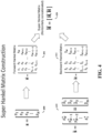
  • Figure 4 shows Hankel matrix construction with horizontal concatenation, in accordance with the present disclosure.
  • an array vector s is used to generate a forward Hankel matrix 401
  • a backwards array vector s at 410 is used to generate a backwards Hankel matrix 411.
  • a left-right (LR) super Hankel matrix 420 is then formed by concatenating the forward and backward Hankel matrices 401 and 411 horizontally.
  • a backward Hankel matrix 411 is then constructed by spanning the first column and the last row of the Backward Hankel matrix with the two sub-vectors respectively and setting anti-diagonal elements to be equal valued.
  • FIG. 5 shows Hankel matrix construction with vertical concatenation, in accordance with the present disclosure.
  • a top-bottom (TB) super Hankel matrix 520 is formed by concatenating the forward and backward Hankel matrices 401 and 411 vertically.
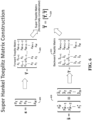
  • Figure 6 shows Toeplitz matrix construction with horizontal concatenation, in accordance with the present disclosure in which a horizontally concatenated super Toeplitz matrix (LR super Toeplitz matrix) is formed by concatenating the forward and backward Hankel matrices.
  • Array vector s (400) is used to generate a forward Toeplitz matrix 601
  • backwards array vector s (410) is used to generate a backwards Toeplitz matrix 611.
  • s s 1 , s 2 , ... , s N T or s 1 , s 2 , ... , , s L + 1 , ... s L + M ⁇ 1 T
  • N L + M - 1
  • two sub-vectors [ s L , s L -1 , ..., s 1 ] T and [ s L ,s L +1 , ... s L + M -1 ] T , overlapped on the first element ( s L ) may be formed for construction of a super Toeplitz matrix 620.
  • sub-vectors [ s L ,s L -1 , ..., s 1 ] T and [ s L ,s L +1 , ... s L + M -1 ] T , span the first column and the first row of the forward Toeplitz matrix 601, respectively.
  • Two index-reversed and complex conjugated sub-vectors [ s 1 , s 2 , ..., s L ] T and [ s L , s L +1 , ..., s L + M -1 ] T are constructed.
  • the backward Toeplitz matrix 611 is constructed by spanning the first column and the first row of the backward Toeplitz matrix with the two sub-vectors respectively ( e.g ., and diagonal elements set to be equal valued).
  • FIG. 7 shows Toeplitz matrix construction with vertical concatenation, in accordance with the present disclosure.
  • a vertically concatenated super Toeplitz matrix (TB super Toeplitz matrix) 720 is formed by concatenating the forward and backward Toeplitz matrices.
  • 2 L targets are modelled in the TB super Hankel/Toeplitz instead of 2M which translate to index from 1 to L in forward Hankel/Toeplitz matrix and index from L+1 to 2L in the backward Hankel/Toeplitz matrix.
  • four different Super Hankel/Toeplitz matrices may thus be computed by:
  • the matrix pencil pair may be directly formed from the super Hankel/ Toeplitz matrix and their general eigenvalues may be estimated.
  • Final DoA estimates may be computed from the phase information of a subset of the eigenvalues whose magnitudes are closest to 1 within a given tolerance.
  • Matrix pencils as referred to herein may be computed in a variety of manners.
  • the following discussion exemplifies such manners, as may be implemented in accordance with one or more embodiments. For instance, the following approach may be implemented with the method depicted in Figure 3 , and/or with one or more of the matrix construction approaches depicted in Figures 4-7 .
  • H ⁇ Signal H ⁇ Signal
  • the horizontally concatenated super Toeplitz matrix (LR super Toeplitz Matrix) may be formed by concatenating the forward and backward Hankel matrices and can be written in the following equation.
  • Super Toeplitz Matrix (2 M targets modelled in the Super Toeplitz):
  • T ⁇ Signal T ⁇ Signal
  • the left-right (LR) super Hankel/Toeplitz matrix may present a rotational invariant property for use in the instant Matrix Pencil approach.
  • the Z matrix in the LR super Hankel matrix model may be written in the following form.
  • Z ⁇ z 1 0 ⁇ z M 0 z M + 1 ⁇ M ⁇ L + 2 ⁇ z 2 M ⁇ M ⁇ L + 2 z 1 1 ⁇ z M 1 z M + 1 ⁇ M ⁇ L + 3 ⁇ z 2 M ⁇ M ⁇ L + 3 ⁇ ⁇ z 1 L ⁇ 2 ⁇ z M L ⁇ 2 z M + 1 ⁇ M ⁇ z 2 M ⁇ M z 1 L ⁇ 1 z M L ⁇ 1 ⁇ M + 1 ⁇ M + 1 ⁇ ⁇ z 2 M ⁇ M + 1 A pair of submatrices ( Z A and Z B ) that are used to form the matrix pencil in the later step are modelled by removing the last row of Z
  • U ⁇ z 1 L ⁇ 1 ⁇ z M L ⁇ 1 z M + 1 ⁇ M + 1 ⁇ z 2 M ⁇ M + 1 z 1 L ⁇ 2 ⁇ z M L ⁇ 2 z M + 1 ⁇ M ⁇ z 2 M ⁇ M ⁇ ⁇ ⁇ z 1 0 ⁇ z M 0 z M + 1 ⁇ M ⁇ L + 2 ⁇ z 2 M ⁇ M ⁇ L + 2
  • a pair of submatrices ( U A and U B ) that are used to form the matrix pencil in the later step may be modelled by removing the first row of U to form U A , and by removing the last row of U to form U B , which can be written in the following form.
  • U B can be factorized by U A and a diagonal matrix, as follows:
  • U ⁇ B z 1 L ⁇ 2 ⁇ z M L ⁇ 2 z M + 1 ⁇ M ⁇ z 2 M ⁇ M z 1 L ⁇ 3 ⁇ z M L ⁇ 3 z M + 1 ⁇ M ⁇ 1 ⁇ z 2 M ⁇ M ⁇ 1 ⁇ ⁇ z 1 0 ⁇ z M 0 z M + 1 ⁇ M ⁇ L + 2 ⁇ z 2 M ⁇ M ⁇ L + 2 z 1 0 ⁇ 0 z 2 M
  • H 1 which is H with the last row removed, is formed with high SNR, H 1 ⁇ Z A ( FY ).
  • this may be equivalent to solving the generalized eigenvalues of matrix pencil [ H 1 , H 2 ].
  • ⁇ and ⁇ can be solved based on the N s eigenvalues whose magnitudes are closest to 1 ( ⁇ they correspond to main diagonals of ⁇ ).
  • an elevation angle may be assumed for evaluating the azimuth angle.
  • N s eigenvalues e.g., min ⁇ L - 1, 2 M ⁇ ⁇ N s , may be used.
  • Source amplitudes may be the main diagonals of F ⁇ ( Z H Z ) -1 Z H HY H ( YY H ) -1 , with Z , Y formed with ⁇ i 's (valid for square or tall matrix Z ).
  • amplitude can be found by DFT's of ⁇ tuned to ⁇ i 's.
  • a vertically concatenated super Hankel/Toeplitz matrix may be implemented in accordance with the following.
  • a top-bottom (TB) Super Hankel Matrix may be formed by concatenating Forward and Backward Hankel matrices vertically and can be written in the following equation.
  • 2 L targets is modelled in the TB Super Hankel/Toeplitz instead of 2M which translate to an index from 1 to L in a forward Hankel/Toeplitz matrix and an index from L+1 to 2L in the backward Hankel/Toeplitz matrix.
  • T ⁇ Signal T ⁇ Signal T ⁇ Signal z 1 L ⁇ 1 ... z L L ⁇ 1 z 1 L ⁇ 2 ... z L L ⁇ 2 ⁇ z 1 0 ⁇ z L 0 z L + 1 ⁇ M + 1 ⁇ z 2 L ⁇ M + 1 z L + 1 ⁇ M ⁇ z 2 L ⁇ M ⁇ z L + 1 ⁇ M ⁇ L + 2 ⁇ z 2 L ⁇ M ⁇ L + 2 ⁇ 1 ⁇ 0 ⁇ ⁇ 0 ⁇ L + 1 * ⁇ 0 ⁇ ⁇ 0 ⁇ 2 L
  • a pair of submatrices ( P A and P B ) that are used to form the matrix pencil in the later step may be modelled by removing the last column of P to form P A , and by removing the first column of P to form P B , which can be written in the following form.
  • P B can be factorized by P A and a diagonal matrix, for instance in the following equation:
  • P ⁇ B z 1 0 ⁇ 0 z 2 L z 1 0 z 1 1 z 1 M ⁇ 2 ⁇ ⁇ ⁇ ⁇ z L 0 z L 1 z L M ⁇ 2 z L + 1 0 z L + 1 1 z L + 1 M ⁇ 2 ⁇ ⁇ ⁇ ⁇ z 2 L 0 z 2 L 1 z 2 L M ⁇ 2
  • the super matrix pencil problem is solved based on a top-bottom (TB) super Hankel/Toeplitz matrix as follows.
  • P B ⁇ P A
  • the super matrix pencil pair [ H 1 , H 2 ] (or equivalently [ H ⁇ 1 H ⁇ 1 H , H ⁇ 2 H ⁇ 1 H ]) for TB super Hankel and matrix pencil pair for TB super Toeplitz [ T 1 , T 2 ] (or equivalently [ T ⁇ 1 T ⁇ 1 H , T ⁇ 2 T ⁇ 1 H ] ) and the associated solver can be formulated based on the following.
  • H 1 which is H with the last column removed, is formed with high SNR, H 1 ⁇ ( OF ) P A .
  • H 2 which is H with the first column removed, is formed.
  • ⁇ and ⁇ can be solved based on the N s eigenvalues whose magnitudes are closest to 1 ( ⁇ they correspond to main diagonals of ⁇ )
  • N s eigenvalues e.g ., min ⁇ 2L, M - 1 ⁇ ⁇ N s .
  • Source amplitudes may be the main diagonals of F ⁇ ( O H O ) -1 O H HP H ( PP H ) -1 with O , P formed with ⁇ i 's (valid for square or fat matrix P ).
  • amplitude can be found by DFT's of ⁇ tuned to ⁇ i 's.
  • circuits or circuitry which may be illustrated as or using terms such as blocks, modules, device, system, unit, controller, interface circuitry, MCPU, and/or other circuit-type depictions (e.g ., reference numerals 120 and 130 of Figure 1 , and 220 and 230 of Figure 2 may depict a block/module as described herein).
  • circuits or circuitry may be used together with other elements to exemplify how certain embodiments may be carried out in the form or structures, steps, functions, operations, activities, etc.
  • circuits or circuitry may correspond to logic circuitry (which may refer to or include a code-programmed/configured CPU or MCPU), in one example the logic circuitry may carry out a process or method (sometimes "algorithm") by performing sampling, transformation, oversampling and inverse transformation. In another example, logic circuitry may carry out a process or method by performing these same activities/operations and, various other radar processing steps in addition. Further operations, processes or methods in this context would be recognized in connection with the functions/activities associated with the processes depicted in Figures 3-7 .
  • one or more modules are discrete logic circuits or programmable logic circuits configured and arranged for implementing these operations/activities, as may be carried out in the approaches shown in Figures 3-7 .
  • a programmable circuit is one or more computer circuits, including memory circuitry for storing and accessing a program to be executed as a set (or sets) of instructions (and/or to be used as configuration data to define how the programmable circuit is to perform).
  • An algorithm or process as described in Figure 3 and/or with the matrix computation(s) in one or more of Figures 4-7 , or as otherwise characterized herein for activities such as computing a target's DoA may be used by the programmable circuit to perform the related steps, functions, operations, activities, etc.
  • the instructions (and/or configuration data) can be configured for implementation in logic circuitry, with the instructions (whether characterized in the form of object code, firmware or software) stored in and accessible from a memory (circuit).

Landscapes

  • Engineering & Computer Science (AREA)
  • Radar, Positioning & Navigation (AREA)
  • Remote Sensing (AREA)
  • Computer Networks & Wireless Communication (AREA)
  • Physics & Mathematics (AREA)
  • General Physics & Mathematics (AREA)
  • Signal Processing (AREA)
  • Radar Systems Or Details Thereof (AREA)

Abstract

Aspects of the present disclosure are directed to radar signal processing apparatuses and methods. As may be implemented in accordance with one or more embodiments, digital signals representative of received reflections of radar signals transmitted towards a target are mathematically processed to provide or construct a matrix pencil based on or as a function of a forward-backward matrix. Eigenvalues of the matrix pencil are computed and an estimation of the direction of arrival (DoA) of the target is output based on the computed eigenvalues.

Description

  • Aspects of various embodiments are directed to estimating a direction of arrival (DoA) of radar signal reflections from a target.
  • A variety of radar communications may be utilized for many different applications. For instance, radar communications may utilize high-resolution imaging radar technology in which computational and algorithmic enhancements are employed to achieve angular resolution superior to the natural resolution provisioned by the physical aperture of an antenna array of the radar system. However, achieving such resolution can be challenging. For instance, as radar targets may be illuminated by the same source, the received echoes can be highly correlated, resulting is an array signal covariance that may need to be further decorrelated before it can be useful. Therefore, an additional decorrelation process such as so-called spatial smoothing may be needed. Spatial smoothing may also be needed for obtaining multiple snapshots of array measurements. However, spatial smoothing approaches may require high computational cost.
  • These and other matters have presented challenges to radar implementations, for a variety of applications.
  • SUMMARY
  • Various example embodiments are directed to issues such as those addressed above and/or others which may become apparent from the following disclosure concerning radar signal processing and related determination of DoA of a target or targets.
  • In accordance with a particular embodiment, a method includes mathematically processing, via logic circuitry, digital signals representative of received reflections of radar signals transmitted towards a target to provide or construct a matrix pencil based on or as a function of a forward-backward matrix. Eigenvalues of the matrix pencil are computed, and an estimation of the DoA of the target is output based on the computed eigenvalues of the matrix pencil.
  • Another embodiment is directed to an apparatus comprising communication circuitry to transmit radar signals and to receive reflections of the radar signals from a target, and processing circuitry process representative signals. Specifically, the processing circuitry mathematically processes digital signals representative of the received reflections of the radar signals to provide or construct a matrix pencil based on or as a function of a forward-backward matrix. The processing circuitry further computes eigenvalues of the matrix pencil, and outputs an estimation of the DoA of the target based on the computed eigenvalues of the matrix pencil.
  • The above discussion/summary is not intended to describe each embodiment or every implementation of the present disclosure. The figures and detailed description that follow also exemplify various embodiments.
  • BRIEF DESCRIPTION OF FIGURES
  • Various example embodiments may be more completely understood in consideration of the following detailed description in connection with the accompanying drawings, in which:
    • FIG. 1 is a system-level diagram illustrating an example radar communications system/apparatus, in accordance with the present disclosure;
    • FIG. 2 shows notional multi-input, multi-output (MIMO) linear-chirp FMCW radar apparatus with forward-backward matrix DoA determination, in accordance with the present disclosure;
    • FIG. 3 shows an array sampling process with matrix calculation, in accordance with the present disclosure;
    • FIG. 4 shows Hankel matrix construction with horizontal concatenation, in accordance with the present disclosure;
    • FIG. 5 shows Hankel matrix construction with vertical concatenation, in accordance with the present disclosure;
    • FIG. 6 shows Toeplitz matrix construction with horizontal concatenation, in accordance with the present disclosure; and
    • FIG. 7 shows Toeplitz matrix construction with vertical concatenation, in accordance with the present disclosure.
  • While various embodiments discussed herein are amenable to modifications and alternative forms, aspects thereof have been shown by way of example in the drawings and will be described in detail. It should be understood, however, that the intention is not to limit the disclosure to the particular embodiments described. On the contrary, the intention is to cover all modifications, equivalents, and alternatives falling within the scope of the disclosure including aspects defined in the claims. In addition, the term "example" as used throughout this application is only by way of illustration, and not limitation.
  • DETAILED DESCRIPTION
  • Aspects of the present disclosure are believed to be applicable to a variety of different types of apparatuses, systems and methods involving processing radar signal reflections to ascertain characteristics of one or more targets from which the reflections are received. In certain implementations, aspects of the present disclosure have been shown to be beneficial when used in the context of automotive or other vehicular radar applications in which the DoA of a target is estimated using high-resolution radar technology, as may be implemented for autonomous driving (AD) and higher-level advanced driver assistance systems (ADAS). In a more particular embodiment, a matrix pencil is constructed using or based on a forward-backward matrix, and eigenvalues of the matrix pencil are utilized for estimating the DoA of a target. For instance, high computational efficiency may be achieved via the employment of a super Hankel matrix. In some implementations, such a matrix may replace the costly process of constructing and eigen-decomposing spatially smoothed signal covariance matrices. While not necessarily so limited, various aspects may be appreciated through the following discussion of non-limiting examples which use exemplary contexts.
  • Accordingly, in the following description various specific details are set forth to describe specific examples presented herein. It should be apparent to one skilled in the art, however, that one or more other examples and/or variations of these examples may be practiced without all the specific details given below. In other instances, well known features have not been described in detail so as not to obscure the description of the examples herein. For ease of illustration, the same reference numerals may be used in different diagrams to refer to the same elements or additional instances of the same element. Also, although aspects and features may in some cases be described in individual figures, it will be appreciated that features from one figure or embodiment can be combined with features of another figure or embodiment even though the combination is not explicitly shown or explicitly described as a combination.
  • In accordance with a particular embodiment digital signals, which are representative of received reflections of radar signals transmitted towards a target, are processed to provide or construct a matrix pencil based on or as a function of a forward-backward matrix. The reflections may be received in a radar circuit that transmits the radar signals, and in some implementations, the digital signals are processed as part of an input array measurement vector (e.g., which may utilize the transmitted signals). Eigenvalues (e.g., eigenvalue phases) of the matrix pencil may be computed, and an estimation of the direction of arrival (DoA) of the target may be generated/output based on the computed eigenvalues of the matrix pencil. For instance, such an output may be based on eigenvalues of the matrix pencil, and eigenvalue phases corresponding to certain of the eigenvalues having a magnitude within a predefined range. In some implementations, halved-degrees-of-freedom issues associated with the matrix pencil and/or the forward-backward matrix are computationally resolved and used with outputting the DoA estimation. Such approaches may be used to estimate the DoA with sufficiently high-resolution imaging based on resolving a number of targets greater than two-thirds the size of the array.
  • The forward-backward matrix may be constructed in a variety of manners. For instance, the forward-backward matrix may include or refer to a matrix having multiple concatenated sub-matrices. Each sub-matrix may be characterized as a diagonal-constant matrix having a diagonal direction consistent with either: each ascending diagonal from left to right being constant (e.g., Hankel-like) or each descending diagonal from left to right being constant (e.g., Toeplitz-like). The forward-backward matrix may include respective forward and backward matrices having the same number of rows and columns.
  • Mathematically processing as noted above may be carried out in a variety of manners. For instance, multiple matrices may be formed in which at least two are characterized as a diagonal-constant matrix having a diagonal direction consistent with either: each ascending diagonal from left to right being constant (e.g., Hankel-like), or each descending diagonal from left to right being constant. (e.g., Toeplitz-like). These may be used to construct a forward-backward matrix as noted. As another example, a forward matrix and a backward matrix respectively constructed of the digital signals may be concatenated, horizontally from left to right and constructing the matrix pencil from the matrices. The forward and backward matrices constructed of the reflections may be concatenated vertically from top to bottom, and the matrix pencil may be constructed from the matrices. In one embodiment, forward and backward Henkel matrices may be generated in which values of rows and columns of the forward and backward matrices are chosen so the resulting matrix is a square or has one more row than columns. In other embodiments, forward and backward Henkel matrices may be generated in which values of rows and columns of the forward and backward matrices are chosen so the resulting matrix is a wide matrix which has more columns than rows to achieve better signal to noise performance in exchange of fewer number of targets to be estimated. In one embodiment, forward and backward Toeplitz matrices may be generated, in which values of the rows and columns of the forward and backward matrices are chosen so the resulting matrix is a square or has one more column than rows. In other embodiments, forward and backward Toeplitz matrices may be generated in which values of rows and columns of the forward and backward matrices are chosen so the resulting matrix is a tall matrix which has more rows than columns to achieve better signal to noise performance in exchange of fewer number of targets to be estimated. Various such approaches may also be combined.
  • The steps of mathematically processing, computing and outputting may omit, for example, providing or estimating a number of signal sources and eliminating noise eigenvectors in an eigenvector matrix or eigenvector matrices. These steps may omit constructing and Eigen-decomposing spatially smoothed signal covariance matrices. Further, these steps may include providing the DoA within an angular resolution of less than 0.05 in a normalized frequency scale of 0-1.
  • Another embodiment is directed to an apparatus having communication circuitry and processing circuitry. The communication circuitry transmits radar signals and receives reflections of the radar signals from a target. The processing circuitry mathematically processes digital signals representative of the received reflections of the radar signals (e.g., as part of an input array measurement vector) to provide or construct a matrix pencil based on or as a function of a forward-backward matrix. The processing circuitry further computes eigenvalues of the matrix pencil, and outputs an estimation of the DoA of the target based on the computed eigenvalues.
  • The processing circuitry may operate in a variety of manners. In a particular embodiment, the processing circuitry forms multiple matrices, at least two of which are characterized as a diagonal-constant matrix having a diagonal direction consistent with either: each ascending diagonal from left to right being constant, or each descending diagonal from left to right being constant.
  • Further, a variety of forward-backward matrices may be utilized. For instance, the forward-backward matrix may include or refer to a matrix having multiple concatenated sub-matrices, each of which is characterized as a diagonal-constant matrix having a diagonal direction consistent with either: each ascending diagonal from left to right being constant, or each descending diagonal from left to right being constant.
  • Turning now to the figures, Figure 1 shows a radar apparatus 100, as may be implemented in accordance with one or more embodiments. The apparatus 100 includes an antenna array 110, radar communication circuitry 120, and radar processing circuitry 130 (which may further interface with interface circuitry 140, for example automotive interface circuitry). The antenna array 110 includes a plurality of antennas, and the radar communication circuitry 120 includes transmission circuitry 122 and reception circuitry 124 (e.g., a plurality of transmitters and receivers). The radar processing circuitry 130 (e.g., radar MCPU) includes a controller module 132, as well as matrix construction and pencil-based DoA computation circuitry 134.
  • These components of apparatus 100 are operable to provide radar communications, in connection with signals communicated with the radar processing circuitry 130, utilizing time-frequency domain oversampling, and as may be implemented in accordance with one or more embodiments herein. For instance, positional characteristics including DoA of a target from which radar signals transmitted by the transmission circuitry 122 via the antenna array 110, and which are reflected from the target and received by the reception circuitry via the antenna array, may be ascertained by constructing a matrix pencil based on or as a function of a forward-backward matrix as characterized herein. Eigenvalues of the matrix pencil are computed and utilized to estimate the DoA. In certain embodiments, the transmission circuitry 122 and reception circuitry 124 are respectively implemented in accordance with the transmitter and receiver circuitry as characterized in communication circuitry 220 in Figure 2.
  • Figure 2 shows notional multi-input, multi-output (MIMO) linear-chirp FMCW radar apparatus 200 with forward-backward matrix DoA determination, as may be utilized in accordance with one or more embodiments. The apparatus 200 includes an antenna array 210, communication circuitry 220 and radar processing circuitry 230. The communication circuitry 220 includes a plurality of transmitters and receivers (e.g., three transmitters and four receivers). The transmitters may include a chirp generator 221 operable to generate respective chirps, and may include other transmission circuitry such as conditioning and amplifier circuits, and operate in response to radar control circuitry within the radar processing circuitry 230.
  • The receivers may include amplifier, filters and other circuits as useful for receiving radar signals. For instance, each receiver may mix a return radar reflection with a transmitted chirp and filter the result to generate deramped IF (intermediate frequency) signals to be sampled by analog-to-digital converters (ADCs) and processed by a digital signal processing (DSP) unit to produce range and Doppler responses for each receive channel. The range-Doppler response maps of the receivers from the transmitted signals may be aggregated to form a complete MIMO array measurement data cube of range-Doppler response maps of antenna elements of a constructed MIMO virtual array. The range-Doppler responses may be non-coherently integrated and target detection may be attempted on the energy-combined range-Doppler map. A detection algorithm, such as may relate to variants of a CFAR algorithm, may be used to identify range-Doppler cells in which targets may be present. For each detection cell, the array measurement vector may then be extracted and processed for identifying the incident angles of any target returns contained in the cell.
  • Reflected radar signals received via the antenna array 210 and communication circuitry 220 are passed to the radar processing circuitry 230. The received signals are processed accordingly, including target DoA estimation at block 232 using a forward-backward matrix and matrix pencil as characterized herein (e.g., as with Figure 1). The radar processing circuitry 230 may further carry out angle estimation and target tracking, using output array vectors, for tracking positional characteristics of targets from which reflections are received. Such target information may be provided via a data interface to external systems (e.g., automotive).
  • Figure 3 shows an array sampling process with matrix calculation, in accordance with the present disclosure. At block 301, an array sample vector corresponding to radar reflections is input and a left-right, top-bottom (LR/TB) super Hankel/Toeplitz matrix is constructed at block 302. At block 303, a matrix pencil is computed directly from the LR/TB super Hankel/Toeplitz matrix, and generalized eigenvalues of the pencil are determined at block 304. Those eigenvalues with magnitudes close to 1 (within a tolerance) are selected at block 305 and their phases are computed at block 306. At block 307, the DoA of a target from which the radar reflections are received is computed from the phase information and DoA estimates of the target are output at block 308. Such an approach may, for example, utilize computations as characterized above and/or with Figures 4-7 that follow.
  • Figure 4 shows Hankel matrix construction with horizontal concatenation, in accordance with the present disclosure. At 400 an array vector s is used to generate a forward Hankel matrix 401, and a backwards array vector s at 410 is used to generate a backwards Hankel matrix 411. A left-right (LR) super Hankel matrix 420 is then formed by concatenating the forward and backward Hankel matrices 401 and 411 horizontally.
  • The forward and backward Hankel matrices may be constructed independently from the array measurements. For instance, for a vector of N elements, s = s 1 , s 2 , , s N T or s 1 , s 2 , , s L , s L + 1 , s L + M 1 T ,
    Figure imgb0001
    wherein N = L + M - 1, two sub-vectors overlapped on the L - th element may be formed. These sub-vectors, [s 1,s 2, ..., sL ] T and [sL ,s L+1, ...s L+M-1] T , span the first column and the last row of the forward Hankel matrix 401, respectively.
  • The backward Hankel matrix may be formed similarly, in which the vector is index-reversed and complex conjugated before the construction. Specifically, a backward array measurement vector s = s 1 , s 2 , , s N T s N * , s N 1 * , , s 1 * T
    Figure imgb0002
    may be formed and two sub-vectors [ s 1, s 2, ..., s L ] T and [ s L , s L+1, ... s L+M-1] T are constructed. A backward Hankel matrix 411 is then constructed by spanning the first column and the last row of the Backward Hankel matrix with the two sub-vectors respectively and setting anti-diagonal elements to be equal valued.
  • Figure 5 shows Hankel matrix construction with vertical concatenation, in accordance with the present disclosure. A top-bottom (TB) super Hankel matrix 520 is formed by concatenating the forward and backward Hankel matrices 401 and 411 vertically.
  • Figure 6 shows Toeplitz matrix construction with horizontal concatenation, in accordance with the present disclosure in which a horizontally concatenated super Toeplitz matrix (LR super Toeplitz matrix) is formed by concatenating the forward and backward Hankel matrices. Array vector s (400) is used to generate a forward Toeplitz matrix 601, and backwards array vector s (410) is used to generate a backwards Toeplitz matrix 611. For the vector 400 of N elements, s = s 1 , s 2 , , s N T or s 1 , s 2 , , , s L + 1 , s L + M 1 T ,
    Figure imgb0003
    where N = L + M - 1, two sub-vectors [sL ,s L-1 , ..., s 1] T and [sL,s L+1, ...s L+M-1] T , overlapped on the first element (sL ), may be formed for construction of a super Toeplitz matrix 620. These sub-vectors, [sL,s L-1, ..., s 1] T and [sL,s L+1, ...s L+M-1] T , span the first column and the first row of the forward Toeplitz matrix 601, respectively. Two index-reversed and complex conjugated sub-vectors [ s 1, s 2, ..., s L ] T and [ s L , s L+1, ..., s L+M-1] T are constructed. The backward Toeplitz matrix 611 is constructed by spanning the first column and the first row of the backward Toeplitz matrix with the two sub-vectors respectively (e.g., and diagonal elements set to be equal valued).
  • Figure 7 shows Toeplitz matrix construction with vertical concatenation, in accordance with the present disclosure. A vertically concatenated super Toeplitz matrix (TB super Toeplitz matrix) 720 is formed by concatenating the forward and backward Toeplitz matrices.
  • Referring to Figures 4-7, 2 L targets are modelled in the TB super Hankel/Toeplitz instead of 2M which translate to index from 1 to L in forward Hankel/Toeplitz matrix and index from L+1 to 2L in the backward Hankel/Toeplitz matrix. Accordingly, four different Super Hankel/Toeplitz matrices may thus be computed by:
    1. 1) concatenating the Forward and Backward Hankel matrices horizontally to form the Left-Right (LR) Super Hankel matrix;
    2. 2) concatenating the Forward and Backward Hankel matrices vertically to form the Top-Bottom (TB) Super Hankel matrix;
    3. 3) concatenating the Forward and Backward Toeplitz matrices horizontally to form the Left-Right (LR) Super Toeplitz matrix; and
    4. 4) concatenating the Forward and Backward Toeplitz matrices horizontally to form the Top-Bottom (TB) Super Toeplitz matrix.
    The sizes of the forward and backward Hankel submatrices may be identical and share the dimensions (L rows and M columns). The values of L and M may be chosen to so the final LR super Hankel matrix/Toeplitz matrix, which is of the size of L rows by 2M columns, is square or a one-row extra tall matrix (e.g., having one more row than columns), which may be implemented to maximize the number of targets detectable. Similarly, the values of L and M may be chosen to so the TB super Hankel matrix/Toeplitz matrix, which is of the size of 2L rows by M columns, is square or a one-column extra wide matrix (e.g., having 1 more columns than rows), as may be implemented to maximize the number of targets detectable. Other sizes of the matrices can be utilized for attaining higher signal to noise performance with fewer targets to be estimated.
  • Once the construction of the LR/TB Super Hankel/Toeplitz matrix is complete. The matrix pencil pair may be directly formed from the super Hankel/ Toeplitz matrix and their general eigenvalues may be estimated. Final DoA estimates may be computed from the phase information of a subset of the eigenvalues whose magnitudes are closest to 1 within a given tolerance.
  • Matrix pencils as referred to herein may be computed in a variety of manners. The following discussion exemplifies such manners, as may be implemented in accordance with one or more embodiments. For instance, the following approach may be implemented with the method depicted in Figure 3, and/or with one or more of the matrix construction approaches depicted in Figures 4-7.
  • Beginning with a horizontally concatenated super Hankel/Toeplitz matrix, a Left-right (LR) super Hankel matrix is formed by concatenating the forward and backward Hankel matrices horizontally and can be written in the following equation (2M targets modelled in the Super Hankel): H Signal = H Signal H Signl = i = 1 M α i z i 0 i = 1 M α i z i 1 i = 1 M α i z i M 1 i = M + 1 2 M α i z i M L + 2 i = M + 1 2 M α i z i M L + 3 i = M + 1 2 M α i z i L + 1 i = 1 M α i z i 1 i = 1 M α i z i 2 i = 1 M α i z i M i = M + 1 2 M α i z i M L + 3 i = M + 1 2 M α i z i M L + 4 i = M + 1 2 M α i z i L + 2 i = 1 M α i z i 2 i = 1 M α i z i 3 i = 1 M α i z i M + 1 i = M + 1 2 M α i z i M L + 4 i = M + 1 2 M α i z i M L + 5 i = M + 1 2 M α i z i L + 2 i = 1 M α i z i L 2 i = 1 M α i z i L 1 i = 1 M α i z i M + L 3 i = M + 1 2 M α i z i M i = M + 1 2 M α i z i M + 1 i = M + 1 2 M α i z i 1 i = 1 M α i z i L 1 i = 1 M α i z i L i = 1 M α i z i M + L 2 i = M + 1 2 M α i z i M + 1 i = M + 1 2 M α i z i M + 2 i = M + 1 2 M α i z i 0 L × 2 M L 2 M = z 1 0 z M 0 z M + 1 M L + 2 z 2 M M L + 2 z 1 1 z M 1 z M + 1 M L + 3 z 2 M M L + 3 z 1 L 1 z M L 1 z M + 1 M + 1 z 2 M M + 1 α 1 0 0 0 α M α M + 1 0 0 0 α 2 M z 1 0 z 1 1 z 1 M 1 0 z M 0 z M 1 z M M 1 z M + 1 0 z M + 1 1 z M + 1 M 1 0 z 2 M 0 z 2 M 1 z 2 M M 1 = Z F Y
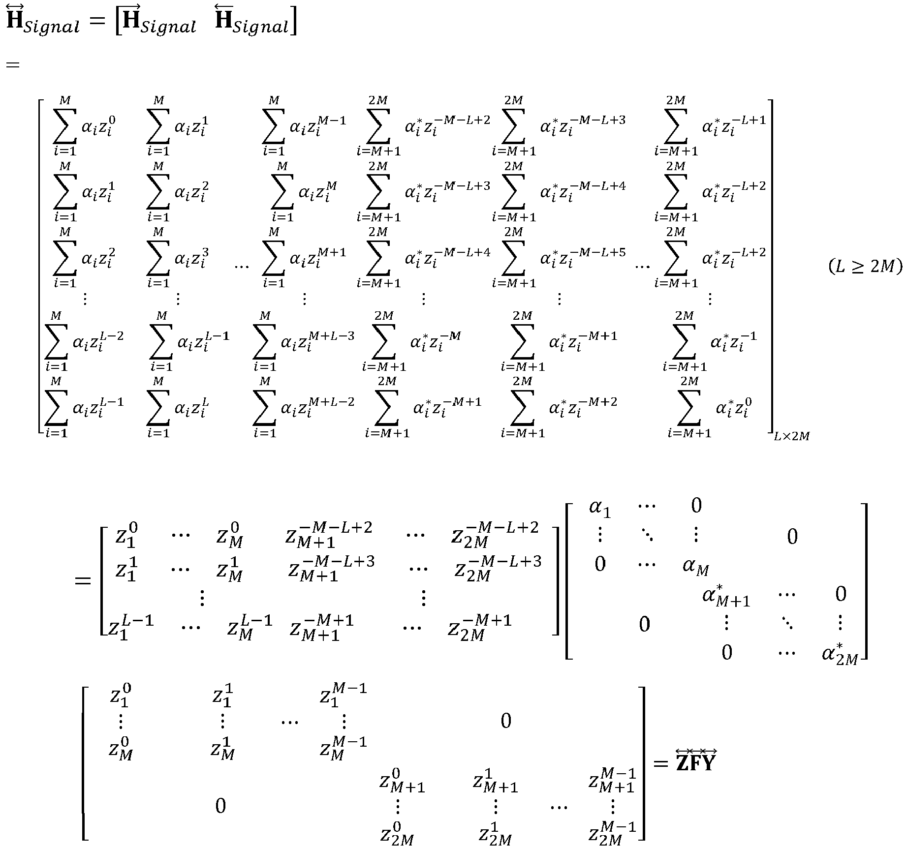
    Figure imgb0004
  • Likewise, the horizontally concatenated super Toeplitz matrix (LR super Toeplitz Matrix) may be formed by concatenating the forward and backward Hankel matrices and can be written in the following equation. Super Toeplitz Matrix (2M targets modelled in the Super Toeplitz): T Signal = T Signal T Signl i = 1 M α i z i L 1 i = 1 M α i z i L i = 1 M α i z i M + L 2 i = M + 1 2 M α i z i M + 1 i = M + 1 2 M α i z i M + 2 i = M + 1 2 M α i z i 0 i = 1 M α i z i L 2 i = 1 M α i z i L 1 i = 1 M α i z i M + L 3 i = M + 1 2 M α i z i M i = M + 1 2 M α i z i M + 1 i = M + 1 2 M α i z i 1 i = 1 M α i z i L 3 i = 1 M α i z i L 2 i = 1 M α i z i M + L 4 i = M + 1 2 M α i z i M 1 i = M + 1 2 M α i z i M i = M + 1 2 M α i z i 2 i = 1 M α i z i 1 i = 1 M α i z i 2 i = 1 M α i z i M i = M + 1 2 M α i z i M L + 3 i = M + 1 2 M α i z i M L + 4 i = M + 1 2 M α i z i L + 2 i = 1 M α i z i 0 i = 1 M α i z i 1 i = 1 M α i z i M 1 i = M + 1 2 M α i z i M L + 2 i = M + 1 2 M α i z i M L + 3 i = M + 1 2 M α i z i L + 1 L × 2 M = z 1 L 1 z M L 1 z M + 1 M + 1 z 2 M M + 1 z 1 L 2 z M L 2 z M + 1 M z 2 M M z 1 0 z M 0 z M + 1 M L + 2 z 2 M M L + 2 α 1 0 0 0 α M α M + 1 0 0 0 α 2 M z 1 0 z 1 1 z 1 M 1 0 z M 0 z M 1 z M M 1 z M + 1 0 z M + 1 1 z M + 1 M 1 0 z 2 M 0 z 2 M 1 z 2 M M 1 = U F Y
    Figure imgb0005
  • Where the number of sources is known, while creating the LR Super Hankel/Toeplitz Matrix one can make 2M = Ns (or Ns + 1 for odd values) so the number of eigenvalues to be computed equals the number of sources, which may improve the SNR as a stronger averaging will take place in the matrix pencil.
  • The left-right (LR) super Hankel/Toeplitz matrix may present a rotational invariant property for use in the instant Matrix Pencil approach. The Z matrix in the LR super Hankel matrix model may be written in the following form. Z = z 1 0 z M 0 z M + 1 M L + 2 z 2 M M L + 2 z 1 1 z M 1 z M + 1 M L + 3 z 2 M M L + 3 z 1 L 2 z M L 2 z M + 1 M z 2 M M z 1 L 1 z M L 1 z M + 1 M + 1 z 2 M M + 1
    Figure imgb0006
    A pair of submatrices (Z A and Z B) that are used to form the matrix pencil in the later step are modelled by removing the last row of Z to form Z A and by removing the first row of Z to form Z B, which can be written in the following form. Z A = z 1 0 z M 0 z M + 1 M L + 2 z 2 M M L + 2 z 1 1 z M 1 z M + 1 M L + 3 z 2 M M L + 3 z 1 L 2 z M L 2 z M + 1 M z 2 M M
    Figure imgb0007
    Z B = z 1 1 z M 1 z M + 1 M L + 3 z 2 M M L + 3 z 1 2 z M 2 z M + 1 M L + 4 z 2 M M L + 4 z 1 L 1 z M L 1 z M + 1 M + 1 z 2 M M + 1
    Figure imgb0008
  • Z B can be factorized by Z A and a diagonal matrix, for instance as follows: Z B = z 1 0 z M 0 z M + 1 M L + 2 z 2 M M L + 2 z 1 1 z M 1 z M + 1 M L + 3 z 2 M M L + 3 z 1 L 1 z M L 1 z M + 1 M + 1 z 2 M M + 1 z 1 0 0 z 2 M
    Figure imgb0009
    Z B = Z A diag z 1 z 2 M = Z A Φ
    Figure imgb0010
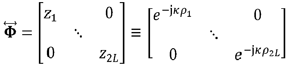
    where Φ = z 1 0 0 z 2 M e j κρ 1 0 0 e j κρ 2 M
    Figure imgb0011
    which demonstrates the rotational or shift invariant property.
  • Similarly, for the LR Super Toeplitz matrix model. The U matrix in the LR super Toeplitz matrix model may be written in the following form. U = z 1 L 1 z M L 1 z M + 1 M + 1 z 2 M M + 1 z 1 L 2 z M L 2 z M + 1 M z 2 M M z 1 0 z M 0 z M + 1 M L + 2 z 2 M M L + 2
    Figure imgb0012
  • A pair of submatrices (U A and U B) that are used to form the matrix pencil in the later step may be modelled by removing the first row of U to form U A, and by removing the last row of U to form U B, which can be written in the following form. Rotational Invariance: U A = z 1 L 2 z M L 2 z M + 1 M z 2 M M z 1 L 3 z M L 3 z M + 1 M 1 z 2 M M 1 z 1 0 z M 0 z M + 1 M L + 2 z 2 M M L + 2
    Figure imgb0013
    U B = z 1 L 1 z M L 1 z M + 1 M + 1 z 2 M M + 1 z 1 L 2 z M L 2 z M + 1 M z 2 M M z 1 1 z M 1 z M + 1 M L + 3 z 2 M M L + 3
    Figure imgb0014
  • In addition, U B can be factorized by U A and a diagonal matrix, as follows: U B = z 1 L 2 z M L 2 z M + 1 M z 2 M M z 1 L 3 z M L 3 z M + 1 M 1 z 2 M M 1 z 1 0 z M 0 z M + 1 M L + 2 z 2 M M L + 2 z 1 0 0 z 2 M
    Figure imgb0015
    U B = U A diag z 1 z 2 M = U A Φ
    Figure imgb0016
    Φ = z 1 0 0 z 2 M e j κρ 1 0 0 e j κρ 2 M
    Figure imgb0017
  • A super Matrix Pencil problem as utilized herein may be solved based on a LR super Hankel/Toeplitz matrix as follows. Having established above rotational invariant property, i.e., Z B = Z A Φ, and U B = U A Φ Super matrix pencil pair [H 1, H 2] (or equivalently [ H 1 H H 1 , H 1 H H 2
    Figure imgb0018
    ]) for LR Super Hankel and matrix pencil pair for LR Super Toeplitz [T 1, T 2] (or equivalently [ T 1 H T 1 , T 1 H T 2
    Figure imgb0019
    ] ) and the associated solver can be formulated based on the following. The duality exists for Hankel ~ Toeplitz, Z ~ U, Z A ~ U A, Z B ~U B, H ~T, T 1 ~ H 1 and T 2 ~ H 2 which means the formula below may be utilized by replacing current symbols with dual symbols.
  • Given Super Hankel matrix H, by definition, H = H Signal + N = ZFY + N. H 1, which is H with the last row removed, is formed with high SNR, H 1Z A (FY). H 2, which is H with the first row removed, is formed with high SNR, H 2Z B (FY) = Z A Φ(FY) where Φ = diag[e -jκρ1 e -jκρ2 ... e -jκρ2M ].
  • The matrix pencil [ H 1 H H 1 , H 1 H H 2
    Figure imgb0020
    ] may be formed and its generalized eigenvalues [µ 1 µ 2 ··· µ 2M ] may be solved via QZ decomposition (e.g., H 1 H H 2 ε = μ H 1 H H 1 ε
    Figure imgb0021
    , where µ ∈ [µ 1 µ 2 ··· µ 2M ] is the generalized eigen value and ε the corresponding generalized eigen vector so µ 1...2M are also the eigenvalues of H 1 H H 1 1 H 1 H H 2
    Figure imgb0022
    ). Conceptually this may be equivalent to solving the generalized eigenvalues of matrix pencil [H 1, H 2].
  • For any eigenvalue µ of the matrix pencil [ H 1 H H 1 , H 1 H H 2
    Figure imgb0023
    ], det { μ H 1 H H 1
    Figure imgb0024
    H 1 H H 2 } = 0
    Figure imgb0025
    can be satisfied, such that
    • - det H 1 H Z A μ I Φ F Y = 0 det μ I Φ = 0 i = 1 2 M μ e jκρ i = 0
      Figure imgb0026
      e jκρ i = μ i ρ i = arg μ i κ
      Figure imgb0027
      , and
    • cosθ i sinϕ i = arg μ i κ
      Figure imgb0028
      may also be satisfied, with eigenvalues having unit magnitudes (e.g., 1).
  • Accordingly, θ and ϕ can be solved based on the Ns eigenvalues whose magnitudes are closest to 1 (∵ they correspond to main diagonals of Φ). For ULA, where it may not possible to unambiguously resolve both the elevation and azimuth angles, an elevation angle may be assumed for evaluating the azimuth angle. At least Ns eigenvalues, e.g., min{L - 1, 2M} ≥ Ns , may be used.
  • Source amplitudes may be the main diagonals of F ≅ (Z H Z)-1 Z H HY H (YY H )-1, with Z, Y formed with µi 's (valid for square or tall matrix Z). For non-square/tall matrix Z case amplitudes may be found by forming a steering matrix (A) with columns of steering vector pointing to the solved angles and solving for the unknown amplitude vector (α) based on the known linear relationship ( = s) (e.g., = (A H A)-1 A H in the least-squares sense). Alternatively, amplitude can be found by DFT's of tuned to µi 's.
  • A vertically concatenated super Hankel/Toeplitz matrix may be implemented in accordance with the following. A top-bottom (TB) Super Hankel Matrix may be formed by concatenating Forward and Backward Hankel matrices vertically and can be written in the following equation. 2L targets is modelled in the TB Super Hankel/Toeplitz instead of 2M which translate to an index from 1 to L in a forward Hankel/Toeplitz matrix and an index from L+1 to 2L in the backward Hankel/Toeplitz matrix. H Signal = H Signal H Signal = z 1 0 z L 0 z 1 1 z L 1 z 1 L 1 z L L 1 z L + 1 M L + 2 z 2 L M L + 2 z L + 1 M L + 3 z 2 L M L + 3 z L + 1 M + 1 z 2 L M + 1 α 1 0 0 α L 0 0 α L + 1 * 0 0 α 2 L * z 0 1 z 1 1 z 1 M 1 z L 0 z L 1 z L M 1 z L + 1 0 z L + 1 1 z L + 1 M 1 z 2 L 0 z 2 L 1 z 2 L 1 z 2 L M 1 = O F P
    Figure imgb0029
  • Likewise, the vertically concatenated super Toeplitz matrix (TB super Toeplitz matrix) may be formed by concatenating the Forward and Backward Hankel matrices and can be written in the following equation. A super Toeplitz Matrix (2L targets modelled in the Super Toeplitz) may be implemented as follows: T Signal = T Signal T Signal
    Figure imgb0030
    z 1 L 1 z L L 1 z 1 L 2 z L L 2 z 1 0 z L 0 z L + 1 M + 1 z 2 L M + 1 z L + 1 M z 2 L M z L + 1 M L + 2 z 2 L M L + 2 α 1 0 0 α L 0 0 α L + 1 * 0 0 α 2 L * z 1 0 z 1 1 z 1 M 1 z L 0 z L 1 z L M 1 z L + 1 0 z L + 1 1 z L + 1 M 1 z 2 L 0 z 2 L 1 z 2 L 1 z 2 L M 1 = B F P
    Figure imgb0031
  • If the number of sources is known, while creating the TB Super Hankel/Toeplitz Matrix one can readily make 2L = Ns (or Ns + 1 for odd values) so the number of eigenvalues to be computed equals to the number of sources. This may improve the SNR as a stronger averaging will take place in the matrix pencil.
  • Super matrix pencil methods as based on TB super Hankel/Toeplitz may be useful for the recovery the DoA's of targets, utilizing rotational invariant property. The Z matrix in the LR Super Hankel matrix model may be written in the following form: P = z 1 0 z 1 1 z 1 M 1 z L 0 z L 1 z L M 1 z L + 1 0 z L + 1 1 z L + 1 M 1 z 2 L 0 z 2 L 1 z 2 L M 1
    Figure imgb0032
    A pair of submatrices (P A and P B) that are used to form the matrix pencil in the later step may be modelled by removing the last column of P to form P A, and by removing the first column of P to form P B, which can be written in the following form. P A = z 1 0 z 1 1 z 1 M 2 z L 0 z L 1 z L M 2 z L + 1 0 z L + 1 1 z L + 1 M 2 z 2 L 0 z 2 L 1 z 2 L M 2
    Figure imgb0033
    P B = z 1 1 z 1 1 z 1 M 1 z L 1 z L 1 z L M 1 z L + 1 1 z L + 1 1 z L + 1 M 1 z 2 L 1 z 2 L 1 z 2 L M 1
    Figure imgb0034
  • Accordingly, P B can be factorized by P A and a diagonal matrix, for instance in the following equation: P B = z 1 0 0 z 2 L z 1 0 z 1 1 z 1 M 2 z L 0 z L 1 z L M 2 z L + 1 0 z L + 1 1 z L + 1 M 2 z 2 L 0 z 2 L 1 z 2 L M 2
    Figure imgb0035
    P B = diag z 1 z 2 L P A = Φ P A
    Figure imgb0036
    where Φ = z 1 0 0 z 2 L e j κρ 1 0 0 e j κρ 2 L
    Figure imgb0037
    which demonstrates a rotational or shift invariant property.
  • In some embodiments, the super matrix pencil problem is solved based on a top-bottom (TB) super Hankel/Toeplitz matrix as follows. Referring to the above rotational invariant property, P B = ΦP A, the super matrix pencil pair [H 1, H 2] (or equivalently [ H 1 H 1 H , H 2 H 1 H
    Figure imgb0038
    ]) for TB super Hankel and matrix pencil pair for TB super Toeplitz [T 1, T 2] (or equivalently [ T 1 T 1 H , T 2 T 1 H
    Figure imgb0039
    ] ) and the associated solver can be formulated based on the following. The duality exists for Hankel ~ Toeplitz, O ~B, H ~T , T 1 ~ H 1 and T 2 ~ H 2 which means the formula below may be used with current symbols replaced by dual symbols. Given Super Hankel matrix H, by definition, H = H Signal + N = OFP + N. H 1, which is H with the last column removed, is formed with high SNR, H 1 ≅ (OF)P A. H 2, which is H with the first column removed, is formed. By definition with high SNR, H 2 ≅ (OF)P B = (OF)ΦP A where Φ = diag[e -jκρ e -jκρ2 ... e -jκρ2L ]
  • The matrix pencil [ H 1 H 1 H , H 2 H 1 H
    Figure imgb0040
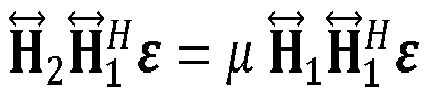
    ] may be formed and its generalized eigenvalues [µ 1 µ 2 ... µ 2M ] solved via QZ decomposition (e.g., H 2 H 1 H ε = μ H 1 H 1 H ε
    Figure imgb0041
    , where µ ∈ [µ 1 µ 2 ... µ 2M ] is the generalized eigen value and ε the corresponding generalized eigen vector so µ 1...2M are also the eigenvalues of H 1 H 1 H 1 H 2 H 1 H
    Figure imgb0042
    ). Conceptually this may be equivalent to solving the generalized eigenvalues of matrix pencil [H 1, H 2]. For instance, for any eigenvalue µ of the matrix pencil [ H 1 H 1 H , H 2 H 1 H
    Figure imgb0043
    ], det μ H 1 H 1 H H 2 H 1 H = 0
    Figure imgb0044
    may be satisfied, such that
    • det O F μ I Φ P A H 1 H = 0 det μ I Φ = 0 i = 1 2 M μ e jκρ i = 0 e jκρ i =
      Figure imgb0045
      μ i ρ i = arg μ i κ
      Figure imgb0046
    • cosθ i sinϕ i = arg μ i κ
      Figure imgb0047
    May also be satisfied with correct eigenvalues should have unit magnitudes (e.g., 1).
  • Accordingly, θ and ϕ can be solved based on the Ns eigenvalues whose magnitudes are closest to 1 (∵ they correspond to main diagonals of Φ) For ULA, it may not be possible to unambiguously resolve both the elevation and azimuth angles. Usually an elevation angle is assumed for evaluating the azimuth angle. At least Ns eigenvalues, e.g., min{2L, M - 1} ≥ Ns , may be used.
  • Source amplitudes may be the main diagonals of F ≅ (O H O)-1 O H HP H (PP H )-1 with O , P formed with µ i's (valid for square or fat matrix P). For a non-square/fat matrix P case, amplitudes may be found by forming a steering matrix (A) with columns of steering vector pointing to the solved angles and solving for the unknown amplitude vector (α) based on the known linear relationship ( = s) (e.g. = (A H A)-1 A H in the least-squares sense). Alternatively, amplitude can be found by DFT's of tuned to µi 's.
  • As examples, the Specification describes and/or illustrates aspects useful for implementing the claimed disclosure by way of various circuits or circuitry which may be illustrated as or using terms such as blocks, modules, device, system, unit, controller, interface circuitry, MCPU, and/or other circuit-type depictions (e.g., reference numerals 120 and 130 of Figure 1, and 220 and 230 of Figure 2 may depict a block/module as described herein). Such circuits or circuitry may be used together with other elements to exemplify how certain embodiments may be carried out in the form or structures, steps, functions, operations, activities, etc. As examples, wherein such circuits or circuitry may correspond to logic circuitry (which may refer to or include a code-programmed/configured CPU or MCPU), in one example the logic circuitry may carry out a process or method (sometimes "algorithm") by performing sampling, transformation, oversampling and inverse transformation. In another example, logic circuitry may carry out a process or method by performing these same activities/operations and, various other radar processing steps in addition. Further operations, processes or methods in this context would be recognized in connection with the functions/activities associated with the processes depicted in Figures 3-7.
  • Embodiments of the present disclosure may include features recited in the following numbered clauses:
    1. 1. A method comprising:
      • mathematically processing, via logic circuitry, digital signals representative of received reflections of radar signals transmitted towards a target to provide or construct a matrix pencil based on or as a function of a forward-backward matrix;
      • computing eigenvalues of the matrix pencil; and
      • outputting an estimation of the direction of arrival (DoA) of the target based on the computed eigenvalues of the matrix pencil.
    2. 2. The method of clause 1, further including transmitting, in a radar circuit, the radar signals and receiving, in the radar circuit, the reflections of the transmitted radar signals, wherein mathematically processing includes processing the digital signals as part of an input array measurement vector.
    3. 3. The method of clause 1, wherein mathematically processing includes forming multiple matrices, at least two of which are characterized as a diagonal-constant matrix having a diagonal direction consistent with either: each ascending diagonal from left to right being constant, or each descending diagonal from left to right being constant.
    4. 4. The method of clause 1, wherein the forward-backward matrix includes or refers to a matrix having multiple concatenated sub-matrices, each of which is characterized as a diagonal-constant matrix having a diagonal direction consistent with either: each ascending diagonal from left to right being constant or each descending diagonal from left to right being constant.
    5. 5. The method of clause 1, wherein the steps of mathematically processing, computing and outputting an estimation of the DoA use sufficiently high-resolution imaging based on resolving a number of targets greater than two-thirds the size of the matrix.
    6. 6. The method of clause 1, wherein the steps of mathematically processing, computing and outputting do not include providing or estimating a number of signal sources and eliminating noise eigenvectors in an eigenvector matrix or eigenvector matrices.
    7. 7. The method of clause 1, further including computationally resolving a halved-degrees-of-freedom issues associated with the matrix pencil and/or the forward-backward matrix, and wherein said outputting an estimation of the DoA is in response to said computationally resolving a halved-degrees-of-freedom issues.
    8. 8. The method of clause 1, wherein the steps of mathematically processing, computing and outputting do not include constructing and Eigen-decomposing spatially smoothed signal covariance matrices.
    9. 9. The method of clause 1, wherein computing eigenvalues of the matrix pencil includes computing eigenvalue phases of the matrix pencil.
    10. 10. The method of clause 1, wherein the steps of mathematically processing, computing and outputting include providing the DoA within an angular resolution of less than 0.05 in a normalized frequency scale of 0-1.
    11. 11. The method of clause 1, wherein outputting an estimation of the DoA of the target based on eigenvalue phases of the matrix pencil is based on or a function of:
      • eigenvalues of the matrix pencil; and
      • eigenvalue phases corresponding to certain of the eigenvalues having a magnitude within a predefined range.
    12. 12. The method of clause 1, wherein mathematically processing the digital signals includes:
      • concatenating a forward matrix and a backward matrix respectively constructed of the digital signals, horizontally from left to right; and
      • constructing the matrix pencil from the matrices.
    13. 13. The method of clause 1, wherein mathematically processing the digital signals includes:
      • concatenating a forward matrix and a backward matrix respectively constructed of the reflections, vertically from top to bottom; and
      • constructing the matrix pencil from the matrices.
    14. 14. The method of clause 1, wherein mathematically processing the digital signals includes generating forward and backward Henkel matrices in which values of rows and columns of the forward and backward matrices are chosen so the resulting matrix is a square or has one more row than columns.
    15. 15. The method of clause 1, wherein mathematically processing the digital signals includes generating forward and backward Toeplitz matrices in which values of the rows and columns of the forward and backward matrices are chosen so the resulting matrix is a square or has one more column than rows.
    16. 16. The method of clause 1, wherein the forward-backward matrix includes forward and backward matrices having the same number of rows and columns.
    17. 17. An apparatus comprising:
      • communication circuitry to transmit radar signals and to receive reflections of the radar signals from a target; and
      • processing circuitry to:
        • mathematically process digital signals representative of the received reflections of the radar signals to provide or construct a matrix pencil based on or as a function of a forward-backward matrix;
        • compute eigenvalues of the matrix pencil; and
        • output an estimation of the direction of arrival (DoA) of the target based on the computed eigenvalues of the matrix pencil.
    18. 18. The apparatus of clause 17, wherein the processing circuitry is to process the digital signals as part of an input array measurement vector.
    19. 19. The apparatus of clause 17, wherein the processing circuitry is to form multiple matrices, at least two of which are characterized as a diagonal-constant matrix having a diagonal direction consistent with either: each ascending diagonal from left to right being constant, or each descending diagonal from left to right being constant.
    20. 20. The apparatus of clause 17, wherein the forward-backward matrix includes or refers to a matrix having multiple concatenated sub-matrices, each of which is characterized as a diagonal-constant matrix having a diagonal direction consistent with either: each ascending diagonal from left to right being constant, or each descending diagonal from left to right being constant.
  • For example, in certain of the above-discussed embodiments, one or more modules are discrete logic circuits or programmable logic circuits configured and arranged for implementing these operations/activities, as may be carried out in the approaches shown in Figures 3-7. In certain embodiments, such a programmable circuit is one or more computer circuits, including memory circuitry for storing and accessing a program to be executed as a set (or sets) of instructions (and/or to be used as configuration data to define how the programmable circuit is to perform). An algorithm or process as described in Figure 3 and/or with the matrix computation(s) in one or more of Figures 4-7, or as otherwise characterized herein for activities such as computing a target's DoA may be used by the programmable circuit to perform the related steps, functions, operations, activities, etc. Depending on the application, the instructions (and/or configuration data) can be configured for implementation in logic circuitry, with the instructions (whether characterized in the form of object code, firmware or software) stored in and accessible from a memory (circuit).
  • Based upon the above discussion and illustrations, those skilled in the art will readily recognize that various modifications and changes may be made to the various embodiments without strictly following the exemplary embodiments and applications illustrated and described herein. For example, methods as exemplified in the Figures may involve steps carried out in various orders, with one or more aspects of the embodiments herein retained, or may involve fewer or more steps. For instance, some embodiments are directed to fewer than all steps and/or components, such as to carry out one or more types of matrix generation and subsequent use thereof. Such modifications do not depart from the scope of various aspects of the disclosure, including aspects set forth in the claims.

Claims (15)

  1. An apparatus comprising:
    communication circuitry to transmit radar signals and to receive reflections of the radar signals from a target; and
    processing circuitry to:
    mathematically process digital signals representative of the received reflections of the radar signals to provide or construct a matrix pencil based on or as a function of a forward-backward matrix;
    compute eigenvalues of the matrix pencil; and
    output an estimation of the direction of arrival (DoA) of the target based on the computed eigenvalues of the matrix pencil.
  2. The apparatus of claim 1, wherein the processing circuitry is to process the digital signals as part of an input array measurement vector.
  3. The apparatus of any of claims 1 or 2, wherein the processing circuitry is to form multiple matrices, at least two of which are characterized as a diagonal-constant matrix having a diagonal direction consistent with either: each ascending diagonal from left to right being constant, or each descending diagonal from left to right being constant.
  4. The apparatus of any of claim 1 to 3, wherein the forward-backward matrix includes or refers to a matrix having multiple concatenated sub-matrices, each of which is characterized as a diagonal-constant matrix having a diagonal direction consistent with either: each ascending diagonal from left to right being constant, or each descending diagonal from left to right being constant.
  5. A method comprising:
    mathematically processing, via logic circuitry, digital signals representative of received reflections of radar signals transmitted towards a target to provide or construct a matrix pencil based on or as a function of a forward-backward matrix;
    computing eigenvalues of the matrix pencil; and
    outputting an estimation of the direction of arrival (DoA) of the target based on the computed eigenvalues of the matrix pencil.
  6. The method of claim 5, further including transmitting, in a radar circuit, the radar signals and receiving, in the radar circuit, the reflections of the transmitted radar signals, wherein mathematically processing includes processing the digital signals as part of an input array measurement vector.
  7. The method of any of claims 5 to 6, wherein mathematically processing includes forming multiple matrices, at least two of which are characterized as a diagonal-constant matrix having a diagonal direction consistent with either: each ascending diagonal from left to right being constant, or each descending diagonal from left to right being constant.
  8. The method of any of claims 5 to 7, wherein the forward-backward matrix includes or refers to a matrix having multiple concatenated sub-matrices, each of which is characterized as a diagonal-constant matrix having a diagonal direction consistent with either: each ascending diagonal from left to right being constant or each descending diagonal from left to right being constant.
  9. The method of any of claims 6 to 8, wherein the steps of mathematically processing, computing and outputting an estimation of the DoA use sufficiently high-resolution imaging based on resolving a number of targets greater than two-thirds the size of the matrix.
  10. The method of any of claims 5 to 9, wherein the steps of mathematically processing, computing and outputting do not include providing or estimating a number of signal sources and eliminating noise eigenvectors in an eigenvector matrix or eigenvector matrices.
  11. The method of any of claims 5 to 10, further including computationally resolving a halved-degrees-of-freedom issues associated with the matrix pencil and/or the forward-backward matrix, and wherein said outputting an estimation of the DoA is in response to said computationally resolving a halved-degrees-of-freedom issues.
  12. The method of any of claims 5 to 11, wherein the steps of mathematically processing, computing and outputting do not include constructing and Eigen-decomposing spatially smoothed signal covariance matrices.
  13. The method of any of claims 5 to 12, wherein computing eigenvalues of the matrix pencil includes computing eigenvalue phases of the matrix pencil.
  14. The method of any of claims 5 to 13, wherein the steps of mathematically processing, computing and outputting include providing the DoA within an angular resolution of less than 0.05 in a normalized frequency scale of 0-1.
  15. The method of any of claims 5 to 14, wherein outputting an estimation of the DoA of the target based on eigenvalue phases of the matrix pencil is based on or a function of:
    eigenvalues of the matrix pencil; and
    eigenvalue phases corresponding to certain of the eigenvalues having a magnitude within a predefined range.
EP22185175.1A 2021-07-28 2022-07-15 Radar signal processing with forward-backward matrix Pending EP4124881A1 (en)

Applications Claiming Priority (1)

Application Number Priority Date Filing Date Title
US17/387,128 US11799537B2 (en) 2021-07-28 2021-07-28 Radar signal processing with forward-backward matrix

Publications (1)

Publication Number Publication Date
EP4124881A1 true EP4124881A1 (en) 2023-02-01

Family

ID=82608384

Family Applications (1)

Application Number Title Priority Date Filing Date
EP22185175.1A Pending EP4124881A1 (en) 2021-07-28 2022-07-15 Radar signal processing with forward-backward matrix

Country Status (3)

Country Link
US (1) US11799537B2 (en)
EP (1) EP4124881A1 (en)
CN (1) CN115685112A (en)

Families Citing this family (1)

* Cited by examiner, † Cited by third party
Publication number Priority date Publication date Assignee Title
US12345797B2 (en) * 2022-11-19 2025-07-01 Nxp B.V. Super-resolution MIMO sparse array automotive radar based on forward and backward hankel matrix completion

Citations (1)

* Cited by examiner, † Cited by third party
Publication number Priority date Publication date Assignee Title
US20100265138A1 (en) * 2009-04-17 2010-10-21 Alain Biem Determining a direction of arrival of signals incident to a tripole sensor

Family Cites Families (16)

* Cited by examiner, † Cited by third party
Publication number Priority date Publication date Assignee Title
GB1167671A (en) * 1968-02-20 1969-10-22 Hughes Aircraft Co Improvements in Pulse Radar
US6567034B1 (en) 2001-09-05 2003-05-20 Lockheed Martin Corporation Digital beamforming radar system and method with super-resolution multiple jammer location
US6653973B2 (en) 2001-09-07 2003-11-25 Lockheed Martin Corporation Adaptive digital beamforming radar method and system for maintaining multiple source angle super-resolution capability in jamming
CA2506779A1 (en) * 2002-11-22 2004-06-10 Ben Gurion University Smart antenna system with improved localization of polarized sources
JP4131466B2 (en) 2003-04-02 2008-08-13 三菱電機株式会社 Image radar apparatus and super-resolution processing method
US7574333B2 (en) * 2004-02-05 2009-08-11 Honeywell International Inc. Apparatus and method for modeling relationships between signals
KR100992929B1 (en) * 2008-06-18 2010-11-08 한양대학교 산학협력단 Distance measuring device and method using chirp signals of different bands
US7855681B2 (en) * 2008-11-19 2010-12-21 Harris Corporation Systems and methods for determining element phase center locations for an array of antenna elements
US20120268315A1 (en) * 2009-10-21 2012-10-25 Anatol Zymunt Tirkel Wide area detection of insects using reflected microwaves
US9405008B2 (en) * 2013-05-17 2016-08-02 Massachusetts Institute Of Technology Methods and apparatus for multi-frequency camera
US10613208B2 (en) 2015-05-15 2020-04-07 Texas Instruments Incorporated Low complexity super-resolution technique for object detection in frequency modulation continuous wave radar
FR3070766B1 (en) * 2017-09-01 2019-09-13 Thales IMPROVED RADAR SYSTEM FOR ENHANCED TRACKING
US10999848B2 (en) * 2018-10-01 2021-05-04 Research & Business Foundation Sungkyunkwan University Sparse-coded ambient backscatter communication method and system
CN111157995A (en) * 2020-01-06 2020-05-15 电子科技大学 Side view angle super-resolution imaging method for automobile radar
US11729583B2 (en) * 2020-04-22 2023-08-15 The Regents Of The University Of California Systems and methods for TOA and DOA acquisition and tracking for signal of opportunity positioning
US11792049B2 (en) * 2021-03-15 2023-10-17 Phasorlab, Inc. Positioning using synthesized wideband channel estimation and synchronized receivers

Patent Citations (1)

* Cited by examiner, † Cited by third party
Publication number Priority date Publication date Assignee Title
US20100265138A1 (en) * 2009-04-17 2010-10-21 Alain Biem Determining a direction of arrival of signals incident to a tripole sensor

Non-Patent Citations (2)

* Cited by examiner, † Cited by third party
Title
GABER ABDO ET AL: "A Study of Wireless Indoor Positioning Based on Joint TDOA and DOA Estimation Using 2-D Matrix Pencil Algorithms and IEEE 802.11ac", IEEE TRANSACTIONS ON WIRELESS COMMUNICATIONS, IEEE SERVICE CENTER, PISCATAWAY, NJ, US, vol. 14, no. 5, 31 December 2014 (2014-12-31), pages 2440 - 2454, XP011580889, ISSN: 1536-1276, [retrieved on 20150507], DOI: 10.1109/TWC.2014.2386869 *
YILMAZER N ET AL: "DOA Estimation using Matrix Pencil and ESPRIT methods using single and multiple snapshots", ELECTROMAGNETIC THEORY (EMTS), 2010 URSI INTERNATIONAL SYMPOSIUM ON, IEEE, PISCATAWAY, NJ, USA, 16 August 2010 (2010-08-16), pages 215 - 218, XP032393258, ISBN: 978-1-4244-5155-5, DOI: 10.1109/URSI-EMTS.2010.5637087 *

Also Published As

Publication number Publication date
CN115685112A (en) 2023-02-03
US11799537B2 (en) 2023-10-24
US20230053001A1 (en) 2023-02-16

Similar Documents

Publication Publication Date Title
EP4050364B1 (en) Radar detection using angle of arrival estimation based on scaling parameter with pruned sparse learning of support vector
EP2293094B1 (en) Method of estimating direction of arrival and apparatus thereof
Chintagunta et al. 2D-DOD and 2D-DOA estimation using the electromagnetic vector sensors
CN102466794B (en) Radar equipment
EP4050363B1 (en) Radar-based detection using sparse array processing
Häcker et al. Single snapshot DOA estimation
Northardt et al. Spatial compressive sensing for direction-of-arrival estimation with bias mitigation via expected likelihood
EP4050372A1 (en) Radar-based detection using angle of arrival estimation based on pruned sparse learning of support vector
US10481242B2 (en) Method for joint antenna-array calibration and direction of arrival estimation for automotive applications
EP4050373A1 (en) Radar-based detection using angle of arrival estimation based on sparse array processing
Wen et al. Direction finding for bistatic MIMO radar with unknown spatially colored noise
US10187134B1 (en) Tx beamformer in MIMO radar
US20230152436A1 (en) System and Method for Determining Angle of Arrival in a Radar Based Point Cloud Generation
Wen et al. Tensor decomposition-based beamspace esprit algorithm for multidimensional harmonic retrieval
Chen et al. Iterative subspace alternating projection method for GNSS multipath DOA estimation
EP4124881A1 (en) Radar signal processing with forward-backward matrix
Qian et al. Localization of coherent signals without source number knowledge in unknown spatially correlated Gaussian noise
Li et al. Enhanced beamspace MUSIC for cost‐effective FMCW automotive radar
CN107450046A (en) Direction of arrival estimation method under low elevation angle multi-path environment
EP4293382B1 (en) METHOD AND CONTROL UNIT FOR INTERNAL CALIBRATION OF A RADAR DEVICE FOR A VEHICLE
Subramaniam et al. Polarization difference smoothing in bistatic MIMO radar
Huang et al. DOA estimation of rectilinear signals with a partly calibrated uniform linear array
Alizadeh et al. Experimental deep learning assisted super-resolution radar imaging
Chen et al. A joint Doppler frequency shift and DoA estimation algorithm based on sparse representations for colocated TDM‐MIMO radar
EP4184207B1 (en) Method and apparatus for determination of direction of arrival angle

Legal Events

Date Code Title Description
PUAI Public reference made under article 153(3) epc to a published international application that has entered the european phase

Free format text: ORIGINAL CODE: 0009012

STAA Information on the status of an ep patent application or granted ep patent

Free format text: STATUS: THE APPLICATION HAS BEEN PUBLISHED

AK Designated contracting states

Kind code of ref document: A1

Designated state(s): AL AT BE BG CH CY CZ DE DK EE ES FI FR GB GR HR HU IE IS IT LI LT LU LV MC MK MT NL NO PL PT RO RS SE SI SK SM TR

STAA Information on the status of an ep patent application or granted ep patent

Free format text: STATUS: REQUEST FOR EXAMINATION WAS MADE

17P Request for examination filed

Effective date: 20230801

RBV Designated contracting states (corrected)

Designated state(s): AL AT BE BG CH CY CZ DE DK EE ES FI FR GB GR HR HU IE IS IT LI LT LU LV MC MK MT NL NO PL PT RO RS SE SI SK SM TR

STAA Information on the status of an ep patent application or granted ep patent

Free format text: STATUS: EXAMINATION IS IN PROGRESS

17Q First examination report despatched

Effective date: 20260304