EP4124842A1 - Method for estimating tire wear and method for determining tire wear shape - Google Patents
Method for estimating tire wear and method for determining tire wear shape Download PDFInfo
- Publication number
- EP4124842A1 EP4124842A1 EP20927520.5A EP20927520A EP4124842A1 EP 4124842 A1 EP4124842 A1 EP 4124842A1 EP 20927520 A EP20927520 A EP 20927520A EP 4124842 A1 EP4124842 A1 EP 4124842A1
- Authority
- EP
- European Patent Office
- Prior art keywords
- tire
- wear
- shape
- acceleration
- center
- Prior art date
- Legal status (The legal status is an assumption and is not a legal conclusion. Google has not performed a legal analysis and makes no representation as to the accuracy of the status listed.)
- Granted
Links
Images




Classifications
-
- B—PERFORMING OPERATIONS; TRANSPORTING
- B60—VEHICLES IN GENERAL
- B60C—VEHICLE TYRES; TYRE INFLATION; TYRE CHANGING; CONNECTING VALVES TO INFLATABLE ELASTIC BODIES IN GENERAL; DEVICES OR ARRANGEMENTS RELATED TO TYRES
- B60C11/00—Tyre tread bands; Tread patterns; Anti-skid inserts
- B60C11/24—Wear-indicating arrangements
- B60C11/246—Tread wear monitoring systems
-
- G—PHYSICS
- G01—MEASURING; TESTING
- G01M—TESTING STATIC OR DYNAMIC BALANCE OF MACHINES OR STRUCTURES; TESTING OF STRUCTURES OR APPARATUS, NOT OTHERWISE PROVIDED FOR
- G01M17/00—Testing of vehicles
- G01M17/007—Wheeled or endless-tracked vehicles
- G01M17/02—Tyres
-
- G—PHYSICS
- G01—MEASURING; TESTING
- G01P—MEASURING LINEAR OR ANGULAR SPEED, ACCELERATION, DECELERATION, OR SHOCK; INDICATING PRESENCE, ABSENCE, OR DIRECTION, OF MOVEMENT
- G01P15/00—Measuring acceleration; Measuring deceleration; Measuring shock, i.e. sudden change of acceleration
- G01P15/18—Measuring acceleration; Measuring deceleration; Measuring shock, i.e. sudden change of acceleration in two or more dimensions
-
- B—PERFORMING OPERATIONS; TRANSPORTING
- B60—VEHICLES IN GENERAL
- B60C—VEHICLE TYRES; TYRE INFLATION; TYRE CHANGING; CONNECTING VALVES TO INFLATABLE ELASTIC BODIES IN GENERAL; DEVICES OR ARRANGEMENTS RELATED TO TYRES
- B60C19/00—Tyre parts or constructions not otherwise provided for
- B60C2019/004—Tyre sensors other than for detecting tyre pressure
Definitions
- the present invention relates to a method for estimating a degree of wear of a tire and a method for determining whether a wear shape of the tire during travelling is center wear or not.
- a method for estimating a degree of wear of a tire there has been proposed a method which includes disposing an acceleration sensor inside the tire; calculating an index of deformation velocity at a contact edge of the tire, the index being magnitude of one of or both of positive and negative peaks detected by the acceleration sensor and appearing in a differential waveform of acceleration in a radial direction around the contact edge; calculating a contact time ratio of contact time to rotation time of the tire, the contact time being a time interval between the positive peak and the negative peak, and the rotation time of the tire being a time interval between either of the positive peaks or the negative peaks; and estimating the degree of wear of the tire from the calculated index of deformation velocity and the contact time ratio and maps which have been obtained in advance and which represent relationships among a residual groove amount which is the degree of wear of the tire, the index of deformation velocity and the contact time ratio (See, for example, Patent Document 1).
- Patent Document 1 WO2009/008502A1
- Fig. 12 is a diagram illustrating a relationship between a derivative peak value (Derivative Peak) of acceleration in the tire radial direction and the contact time ratio (Contact Time Ratio), which were measured by running, at a constant velocity, a vehicle equipped with four types of test tires, namely, a new tire ( ⁇ ; New), two types of tires ( ⁇ , ⁇ ; Mid-worm) whose wear shape is different from each other and whose residual groove amount is half of the new tire, and a tire worn to near a slip sign ( ⁇ ; Full- worm).
- the mark ⁇ (circle) indicates a tire whose wear shape is center wear (Center)
- the mark ⁇ (triangle) indicate a tire whose wear shape is even wear (Even).
- derivative peak values of the acceleration in the tire radial direction in plural contact time ratios were measured.
- the present invention has been made in view of the conventional problem and aims at providing a method for determining whether the wear shape of a tire is the center wear or not, and a method for accurately estimating the degree of wear of the tire during travelling regardless of the wear shape of the tire.
- An aspect of the present invention relates to a method for estimating a degree of wear (a residual groove amount or a wear amount) of a tire during travelling, in which the degree of wear is estimated by using: an index of deformation velocity at a tire contact edge or in the vicinity of the tire contact edge, the index of the deformation velocity having been calculated from magnitude (a derivative peak value at a contact edge) of one of or both of positive and negative peaks appearing in a radial acceleration waveform obtained by differentiating a time-series waveform of tire radial acceleration detected by an acceleration sensor mounted on the tire; a contact time ratio of contact time to tire rotation time, the contact time being a time interval between the positive peak and the negative peak, the tire rotation time being a time interval between either of positive peaks or negative peaks; and a deflection amount which is a difference between a tire radius and an effective radius (a distance between the center of the axle and the road surface), the tire radius being a radius of the tire under a non-loaded state and the effective radius being a radius
- the degree of wear of the tire was estimated by using the deflection amount of the tire as a measure of wear in addition to the index of the deformation velocity and the contact time ratio of the tire during travelling, the degree of wear of the tire can be estimated with high accuracy regardless of whether the wear shape of the tire is the center wear or not.
- the degree of wear of the tire may be obtained from a regression formula, which has been obtained in advance, using as variables, the index of deformation velocity, the contact time ratio and the deflection amount, or after determining whether the wear shape is the center wear or not, if it is the center wear, the degree of wear estimated from the index of deformation velocity and the contact time ratio may be corrected.
- two master curves which are a master curve of the even wear and a master curve of the center wear, may be prepared, and the master curve may be selected according to the wear shape.
- Fig. 1 is a diagram illustrating a configuration of a tire wear estimation device 10 according to a first embodiment of the present invention.
- the tire wear estimation device 10 includes first and second acceleration sensors 11A and 11B, an acceleration differential waveform arithmetic means 12, a derivative peak value calculating means 13, a contact time ratio calculating means 14, an angular velocity estimating means 15, a deflection amount calculating means 16, a memory means 17, and a residual groove amount estimating means 18.
- Each of the means from the acceleration differential waveform arithmetic means 12 to the residual groove amount estimating means 18 is configured by, for example, computer software and memories such as a RAM and the like.
- each of the means from the acceleration differential waveform arithmetic means 12 to the residual groove amount estimating means 18 is referred to as an arithmetic unit 10B.
- the arithmetic unit 10B was installed on the vehicle body side, but it may be installed inside the tire.
- the first and second acceleration sensors 11A and 11B are both housed in a sensor case 11 disposed approximately at the center on a tire air chamber 3 side of an inner liner part 2 of the tire 1, and detect vibrations, as acceleration, input from a road surface to a tread 4.
- the first acceleration sensor 11A is so disposed that a detection direction becomes the tire radial direction, and detects tire radial acceleration a R (t) input from the road surface
- the second acceleration sensor 11B is so disposed that a detection direction becomes the tire circumferential direction and detects tire circumferential acceleration a T (t).
- the x direction is a vehicle travel direction
- the y direction is a vehicle width direction (tire width direction)
- the z direction is a vertical direction.
- amplifiers that amplify outputs of the first and second acceleration sensors 11A and 11B, respectively, A/D converters, a transmitter that transmits the A/D-converted signals to the arithmetic unit 10B, and other components are housed in the sensor case 11.
- estimation results obtained by the arithmetic unit 10B may be transmitted to a vehicle control unit (not shown) installed on the vehicle body side.
- first and second acceleration sensors 11A and 11B are quite small compared to the size of the tire 1, it can be assumed that these sensors are in approximately the same position.
- the position of the first and second acceleration sensors 11A and 11B, shown at a point A in Fig. 2B is referred to as a measurement point.
- the acceleration differential waveform arithmetic means 12 extracts a radial acceleration waveform, which is a time-series waveform of tire radial acceleration detected by the first acceleration sensor 11A, and calculates an acceleration differential waveform, which is a waveform obtained by time-differentiating the extracted radial acceleration waveform.
- Fig. 3A is a diagram illustrating an example of the radial acceleration waveform, where the horizontal axis is time [sec.] and the vertical axis is acceleration [G].
- a portion where the negative slope becomes maximum is a contact edge p f on a leading-edge side
- a portion where the positive slope becomes maximum is a contact edge p k on a trailing-edge side.
- Fig. 3B is a diagram illustrating an example of the acceleration differential waveform, where the horizontal axis is time [sec.] and the vertical axis is the acceleration differential value [G/sec.].
- this acceleration differential waveform two peaks appear.
- the larger the slope of the radial acceleration waveform at the contact edges P f and P k is, the larger the magnitude of the peaks P f and P k in the acceleration differential waveform become.
- an interval between the peak P f on the leading-edge side and the peak P k on the trailing-edge side in the acceleration differential waveform is contact time T t
- an interval between two temporally adjacent peaks P k and P k+1 on the trailing-edge side is rotation time T which is the time the tire rotates one rotation.
- the rotation time T r may be obtained from a time interval between the peaks on the leading-edge side.
- the derivative peak value calculating means 13 calculates a derivative peak value V Rf on the leading-edge side, which is the magnitude of the peak P f on the leading-edge side, uses this value as a deformation velocity index V R , and sends this deformation velocity index V R to the residual groove amount estimating means 18.
- a derivative peak value V Rk on the trailing-edge side which is the acceleration differential value on the trailing-edge side, may be used, or an average value of the derivative peak value V Rf on the leading-edge side and the derivative peak value V Rk on the trailing-edge side may be used.
- the contact time ratio calculating means 14 calculates the rotation time T r , which is a time difference between time T 1 when the trailing-edge side peak P k has appeared and time T 2 when this trailing-edge side peak appears again after one rotation of the tire 1, and the contact time T t , which is the time between the leading-edge side peal P f and the trailing-edge side peak P k , and calculates the contact time ratio R c obtained by dividing the calculated contact time T t by the rotation time T r .
- the angular velocity estimating means 15 estimates a rotation angular velocity ⁇ (t) of the tire 1 from the tire radial acceleration a R (t) and the tire circumferential acceleration a T (t) respectively detected by the first and second acceleration sensors11A and 11B.
- the deflection amount calculating means 16 calculates the locus of the measurement point A from the tire radial acceleration a R (t) and the tire circumferential acceleration a T (t) respectively detected by the first and second acceleration sensors 11A and 11B, and from the rotation angular velocity ⁇ (t) estimated by the angular velocity estimating means 15, obtains an outer shape of the tire 1, which is a vertical sectional shape of the tire 1 during travelling, and estimates a deformation amount d from this outer shape of the tire 1.
- the memory means 17 stores a plurality of R c -V R maps 17M 1 to 17M n which have been obtained in advance.
- the residual groove amount H is used as the degree of wear, however, a wear amount M may be used as the degree of wear.
- a master line L j representing a relationship, which has been obtained in advance, between the contact time ratio R c and the deformation velocity index V R of a worn tire with the residual groove amount H j is drawn on a plane where the horizontal axis is the contact time ratio R c and the vertical axis is the deformation velocity index V R .
- the R c -V R maps 17M 1 to 17M n can be obtained by using data of the contact time ratio R c , data of the deformation velocity index V R , and data of the deflection amount d, which are the data of the time when a vehicle equipped with multiple test tires including a new tire (New) and a tire worn close to the slip sign (Full-worm), which are different in the residual groove amount H M and the wear shape, was run under various load states.
- the residual groove amount estimating means 18 estimates the residual groove amount H, which is the degree of wear of the tire 1, by using the deformation velocity index V R calculated by the derivative peak value calculating means 13, the contact time ratio R c calculated by the contact time ratio calculating means 14, the deflection amount d calculated by the deflection amount calculating means 16, and the R c -V R maps 17M 1 to 17M n which have been stored in the memory means 17.
- the R c -V R maps 17M 1 to 17M n were obtained by using the tire radial acceleration a R (t) and the tire circumferential acceleration a T (t), which were detected by running the vehicle equipped with the test tires which are different in the residual groove amount H and the wear shape.
- the R c -V R maps 17M 1 to 17M n it is possible to accurately estimate the residual groove amount H regardless of whether the wear shape is the center wear or not.
- a regression formula H F (R c , V R , d), which has been obtained in advance, of the residual groove amount H.
- three of the contact time ratio R c , the deformation velocity index V R and the deflection amount d are used, as variables.
- the first and second acceleration sensors 11A and 11B disposed in the inner liner part 2 of the tire 1 respectively detect the tire radial acceleration a R (t) and the tire circumferential acceleration a T (t), which are input from the road surface to the tire 1 (Step S10).
- the acceleration differential waveform which is the waveform obtained by time-differentiating the tire radial acceleration a R (t)
- the derivative peak value V Rf on the leading-edge side which is the magnitude of the peak P f on the leading-edge side of this acceleration differential waveform, is calculated, and this is used as the deformation velocity index V R (Step S12).
- the contact time ratio R c which is the ratio of the contact time T t to the rotation time T r , is calculated (Step S14).
- the contact time ratio R c can be expressed as T t /T r .
- Step S15 From the tire radial acceleration a R (t) and the tire circumferential acceleration a T (t) detected in Step S10 above, the rotation angular velocity ⁇ (t) of the tire 1 is calculated (Step S15). Then, from the tire radial acceleration a R (t), the tire circumferential acceleration a T (t) and the rotation angular velocity ⁇ (t), the deflection amount d of the tire 1 is calculated (Step S16).
- the calculation of the deformation velocity index V R , the calculation of the contact time ratio R c and the calculation of the deflection amount d are not necessarily be performed in this order, and the sequential order may be changed, or may be processed in parallel.
- Step S17 the residual groove amount H, which is the degree of wear of the tire 1, is estimated (Step S17).
- Step S15 The method for estimating the rotation angular velocity ⁇ (t) in Step S15 is as follows.
- v t ⁇ 0 t a T s ds + V 0
- V 0 the vehicle velocity, which can be calculated from the tire rotation period, the tire radius, GPS data, and so on.
- preprocessing such as centering may be performed.
- the tire circumferential velocity v(t) decreases as approaching the leading-edge, increases again as entering the contact area, but decreases again from near the center of the contact area, reaches the minimum at the trailing-edge, and thereafter increases.
- Fig. 6D illustrates the temporal variation of the estimated value of the rotation angular velocity w(t).
- Equation (2) above was derived on the assumption that the sensor (measurement point A) is in a uniform circular motion at a given time t.
- the acceleration a R (t) and the velocity v(t) when the measurement point A is in the uniform circular motion can be expressed by the following equation.
- R (t) is the radius of curvature at the time t.
- the above equation (2) can be obtained by eliminating R(t) from the above two equations and solving for ⁇ (t).
- Step S16 an explanation is given as to the method for calculating the deflection amount d in Step S16.
- the deflection amount d is calculated from the locus of the measurement point A.
- an estimated value of the rotation angular velocity ⁇ (t) is integrated by using the following equation (3) to obtain a temporally-varying waveform of a rotational angle ⁇ .
- the rotation angle ⁇ of the measurement point is, as illustrated in Fig. 7A , a rotation angle of the measurement point A when viewed from the center of the tire 1, of which initial value ⁇ 0 may be set to any suitable values such as 0 (contact center) or - ⁇ (uppermost part) or other values.
- ⁇ t ⁇ 0 t ⁇ T s ds + ⁇ 0
- the tire radial acceleration a R (t) and the tire circumferential acceleration a T (t) are coordinate-transformed to acceleration in the front-back direction a x (t) and acceleration in the vertical direction a z (t), which are the accelerations of a global coordinate system (x, z).
- the global coordinate system (x, z) is the coordinate system with the x direction being the vehicle travel direction, the y direction being the vehicle width direction (tire width direction) and the z direction being the vertical direction, which are illustrated in Figs. 2A and 2B .
- a x t a T t cos ⁇ t ⁇ a R t sin ⁇ t
- a z t a T t sin ⁇ t + a R t cos ⁇ t
- Temporally-varying waveforms of the acceleration a x (t) in the front-back direction and the acceleration a z (t) in the vertical direction are illustrated in Figs. 7B and 7C .
- a x (t) and a z (t) may involve a preprocessing such as centering.
- initial values v x0 and v z0 may be set to any values.
- Figs. 8A and 8B The temporally-varying waveforms of the front-back direction velocity v x (t) and the vertical direction velocity v z (t) are illustrated in Figs. 8A and 8B .
- v x (t) and v z (t) may involve the preprocessing such as the centering.
- the initial values u x 0 and u z 0 may be set to any values.
- a regression circle C fit is obtained by fitting the circle with respect to the locus of the measurement point A, and a regression radius R fit , which is the radius of the regression circle C fit , is obtained, and also an effective radius R eff , which is the radius of the tire 1 in the deflected state, is obtained.
- the effective radius R eff was set to be the minimum value of the distance from the center O of the regression circle C fit to the measurement point A, as shown by the dashed line in the figure.
- Fig. 10 is a diagram illustrating the configuration of a tire wear estimation device 20 according to a second embodiment of the present invention.
- 11A and 11B are first and second acceleration sensors
- 12 is an acceleration differential waveform arithmetic means
- 13 is a derivative peak value calculating means
- 14 is a contact time ratio calculating means
- 15 is an angular velocity estimating means
- 16 is a deflection amount calculating means
- 21 is an identification model memory means
- 22 is a wear shape determining means
- 23 is an R-V map memory means
- 24 is a residual groove amount estimating means.
- the identification model memory means 21 stores a wear shape identification model 21M which has been obtained in advance.
- the reference feature vector Yzsv and the Lagrange multiplier ⁇ Z are obtained by a support vector machine (SVM) using these feature vectors Y z as learning data.
- the wear shape determining means 22 after calculating the Kernel functions K N (X, Y NSV ) and K M (X, Y MSVV ) by using the feature vector X (R c , V R , d) composed of the deformation velocity index V R calculated by the derivative peak value calculating means 13, the contact time ratio R c calculated by the contact time ratio calculating means 14 and the deflection amount d calculated by the deflection amount calculating means 16, and the support vectors Y NSV and Y MCVV and the Lagrange multipliers ⁇ N and ⁇ M stored in the identification model memory means 21, obtains the value of the identification function f NM (x) for identifying the wear shape of the tire by using these Kernel functions K N (X, Y NSV ) and K M (X, Y MSVV ), and determines, from the value of the identification function f NM (x), whether the wear shape of the tire 1 is the N state (even wear) or the M state (center wear). A result of the determination by
- Kernel functions K N and K M a Gaussian kernel or the like is suitably used, for example.
- the R-V map memory means 23 stores a first R c -V R map 23N (Even-Map) and a second R c -V R map 23M (Center-Map), which have been obtained in advance, in which a first master line L Nj and a second master line L Mj are respectively drawn on a plane whose horizontal axis being the contact time ratio R c and whose vertical axis being the deformation velocity index V R .
- the first master line L Nj represents the relationship between the contact time ratio R c and the deformation velocity index V R of a worn tire whose residual groove amount is H j and whose wear shape is the even wear
- the second master line L Mj represents the relationship between the contact time ratio R c and the deformation velocity index V R of a worn tire whose residual groove amount is H j and whose wear shape is the center wear.
- Each of the first and second R c -V R maps 23N and 23M is a map for estimating the degree of wear from the contact time ratio R c and the deformation velocity index V R .
- the first R c -V R map 23M is obtained by using the data of the contact time ratio R c and the data of the deformation velocity index V R obtained when the vehicle, which was equipped with plural test tires whose wear shape is the even wear and whose residual groove amount H is different from each other, was run under various load conditions.
- the second R c -V R map 23M is obtained by using the data of the contact time ratio R c and the data of the deformation velocity index V R obtained when the vehicle, which was equipped with plural test tires whose wear shape is the center wear and whose residual groove amount H is different from each other, was run under the various load conditions.
- the residual groove amount estimating means 24 estimates the residual groove amount H, which is the degree of wear of the tire 1, by using the deformation velocity index V R calculated by the derivative peak value calculating means 13, the contact time ratio R c calculated by the contact time ratio calculating means 14, and the first R c -V R map 23N or the second R c -V R map 23M having been stored in the R-V map memory means 23.
- the residual groove amount estimating means 24 estimates the residual groove amount H, which is the degree of wear of the tire 1, by using the above-mentioned calculated deformation velocity index V R , the contact time ratio R c and the first R c -V R map 23N.
- the residual groove amount estimating means 24 estimates the residual groove amount H, which is the degree of wear of the tire 1, by using the above-mentioned calculated deformation velocity index V R , the contact time ratio R c and the second R c -V R map 23M.
- the determination was made as to whether the wear shape of the tire is the even wear or the center wear by using a machine learning algorithm, on the basis of the feature amount vector X (R c , V R , d) composed of the above-mentioned calculated deformation velocity index V R , the contact time ratio R c and the deflection amount d, and the determination model (wear shape identification model 21M), which has been obtained in advance for each wear shape and which is structured with, as learning data, the support vector Y Z (R cZ , V RZ , d Z ) which is the feature amount vector.
- the wear shape of the tire 1 can be determined accurately.
- the degree of wear of the tire 1 in question was estimated taking the wear shape into consideration, the degree of wear of the tire during travelling can be accurately estimated regardless of the wear shape of the tire.
- the rotation angular velocity ⁇ (t) was estimated from the tire radial acceleration a R (t) and the tire circumferential acceleration a T (t), however, the rotation angular velocity ⁇ (t) may be directly measured by using an angular velocity sensor such as an oscillation gyroscope. It is preferable to install the angular velocity sensor at the measurement point A.
- the deflection amount d by disposing a distance sensor on the vehicle equipped with the tire 1 and measuring a distance between the vehicle and the road surface, the deflection amount d may be calculated from the distance between the vehicle and the road surface. Specifically, by converting the distance between the disposed position of the distance sensor and the road surface into a distance between the axle and the road surface and using the converted distance as the effective radius R eff , a difference between this effective radius and the tire radius R may be used as the deflection amount d.
- the wear shape determining means 22 was configured of the support vector machine (SVM), however, other machine learning algorithm such as a logistic regression, a random forest, a neural network, or the like may be used.
- SVM support vector machine
- other machine learning algorithm such as a logistic regression, a random forest, a neural network, or the like may be used.
- the wear shape was configured to select the map for estimating the degree of wear by the wear shape.
- H' H' + ⁇ H and output.
Landscapes
- Physics & Mathematics (AREA)
- General Physics & Mathematics (AREA)
- Engineering & Computer Science (AREA)
- Mechanical Engineering (AREA)
- Length Measuring Devices With Unspecified Measuring Means (AREA)
- Tires In General (AREA)
Abstract
Description
- The present invention relates to a method for estimating a degree of wear of a tire and a method for determining whether a wear shape of the tire during travelling is center wear or not.
- Conventionally, as a method for estimating a degree of wear of a tire, there has been proposed a method which includes disposing an acceleration sensor inside the tire; calculating an index of deformation velocity at a contact edge of the tire, the index being magnitude of one of or both of positive and negative peaks detected by the acceleration sensor and appearing in a differential waveform of acceleration in a radial direction around the contact edge; calculating a contact time ratio of contact time to rotation time of the tire, the contact time being a time interval between the positive peak and the negative peak, and the rotation time of the tire being a time interval between either of the positive peaks or the negative peaks; and estimating the degree of wear of the tire from the calculated index of deformation velocity and the contact time ratio and maps which have been obtained in advance and which represent relationships among a residual groove amount which is the degree of wear of the tire, the index of deformation velocity and the contact time ratio (See, for example, Patent Document 1).
- Patent Document 1:
WO2009/008502A1 - However, there has been a problem that, as in the above-mentioned
Patent Document 1, when the residual groove amount of the tire is estimated from the index of the deformation velocity and the contact time ratio, with a tire whose wear shape is the center wear, an actual residual groove amount is detected to be shifted toward a new tire side (the estimated wear amount becomes smaller than the actual wear amount). -
Fig. 12 is a diagram illustrating a relationship between a derivative peak value (Derivative Peak) of acceleration in the tire radial direction and the contact time ratio (Contact Time Ratio), which were measured by running, at a constant velocity, a vehicle equipped with four types of test tires, namely, a new tire (□; New), two types of tires (∘, △; Mid-worm) whose wear shape is different from each other and whose residual groove amount is half of the new tire, and a tire worn to near a slip sign (■; Full- worm). In the figure, the mark ∘ (circle) indicates a tire whose wear shape is center wear (Center), and the mark △ (triangle) indicate a tire whose wear shape is even wear (Even). In this embodiment, by varying the load, derivative peak values of the acceleration in the tire radial direction in plural contact time ratios were measured. - As noted from the figure, the relationship between the index of deformation velocity and the contact time ratio of the tire whose wear shape is the center wear, is shifted toward the new tire side.
- The present invention has been made in view of the conventional problem and aims at providing a method for determining whether the wear shape of a tire is the center wear or not, and a method for accurately estimating the degree of wear of the tire during travelling regardless of the wear shape of the tire.
- An aspect of the present invention relates to a method for estimating a degree of wear (a residual groove amount or a wear amount) of a tire during travelling, in which the degree of wear is estimated by using: an index of deformation velocity at a tire contact edge or in the vicinity of the tire contact edge, the index of the deformation velocity having been calculated from magnitude (a derivative peak value at a contact edge) of one of or both of positive and negative peaks appearing in a radial acceleration waveform obtained by differentiating a time-series waveform of tire radial acceleration detected by an acceleration sensor mounted on the tire; a contact time ratio of contact time to tire rotation time, the contact time being a time interval between the positive peak and the negative peak, the tire rotation time being a time interval between either of positive peaks or negative peaks; and a deflection amount which is a difference between a tire radius and an effective radius (a distance between the center of the axle and the road surface), the tire radius being a radius of the tire under a non-loaded state and the effective radius being a radius of the tire during travelling.
- In this way, since the degree of wear of the tire was estimated by using the deflection amount of the tire as a measure of wear in addition to the index of the deformation velocity and the contact time ratio of the tire during travelling, the degree of wear of the tire can be estimated with high accuracy regardless of whether the wear shape of the tire is the center wear or not.
- Incidentally, the degree of wear of the tire may be obtained from a regression formula, which has been obtained in advance, using as variables, the index of deformation velocity, the contact time ratio and the deflection amount, or after determining whether the wear shape is the center wear or not, if it is the center wear, the degree of wear estimated from the index of deformation velocity and the contact time ratio may be corrected.
- Alternatively, two master curves, which are a master curve of the even wear and a master curve of the center wear, may be prepared, and the master curve may be selected according to the wear shape.
- It should be noted that the above-described summary of the invention does not enumerate all the necessary features of the present invention, and subcombinations of these feature groups can also be the invention.
-
-
Fig. 1 is a functional block diagram illustrating the configuration of a tire wear estimation device according to a first embodiment of the present invention. -
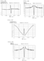
Figs. 2A and 2B are diagrams respectively illustrating an attachment position of an acceleration sensor and a detection direction of acceleration. -
Figs. 3A to 3C are diagrams respectively illustrating an acceleration waveform in the tire radial direction, an example of an acceleration differential waveform, and a method for calculating rotation time and contact time. -
Fig. 4 is a diagram illustrating an example of an Rc-VR map. -
Fig. 5 is a flowchart illustrating a tire wear estimation method according to the first embodiment of the present invention. -
Figs. 6A to 6D are diagrams respectively illustrating temporally varying waveforms of tire circumferential acceleration, tire radial acceleration, tire circumferential velocity, and rotation angular velocity. -
Figs. 7A to 7C are diagrams respectively illustrating temporally varying waveforms of a rotation angle of a measurement point, front-back direction acceleration and vertical direction acceleration. -
Figs. 8A and 8B are diagrams respectively illustrating temporally varying waveforms of a front-back direction velocity and a vertical direction velocity of the measurement point. -
Figs. 9A to 9D are diagrams respectively illustrating temporally varying waveforms of displacement of the measurement point in a front-back direction and a vertical direction, and a locus of the measurement point. -
Fig. 10 is a diagram illustrating the configuration of a tire wear estimation device according to a second embodiment of the present invention. -
Fig. 11 is a schematic diagram illustrating distribution of feature amounts and an identification function which is a separation plane. -
Fig. 12 is a map illustrating a relationship between a deformation velocity index and a contact time ratio of tires whose residual groove amount is different from each other. -
Fig. 1 is a diagram illustrating a configuration of a tirewear estimation device 10 according to a first embodiment of the present invention. The tirewear estimation device 10 includes first andsecond acceleration sensors - Each of the means from the acceleration differential waveform arithmetic means 12 to the residual groove amount estimating means 18 is configured by, for example, computer software and memories such as a RAM and the like. Hereinafter, each of the means from the acceleration differential waveform arithmetic means 12 to the residual groove amount estimating means 18 is referred to as an
arithmetic unit 10B. In this embodiment, thearithmetic unit 10B was installed on the vehicle body side, but it may be installed inside the tire. - As illustrated in
Figs. 2A and 2B , the first andsecond acceleration sensors sensor case 11 disposed approximately at the center on atire air chamber 3 side of aninner liner part 2 of thetire 1, and detect vibrations, as acceleration, input from a road surface to atread 4. - The
first acceleration sensor 11A is so disposed that a detection direction becomes the tire radial direction, and detects tire radial acceleration aR (t) input from the road surface, and thesecond acceleration sensor 11B is so disposed that a detection direction becomes the tire circumferential direction and detects tire circumferential acceleration aT (t). Incidentally, in each figure, the x direction is a vehicle travel direction, the y direction is a vehicle width direction (tire width direction), and the z direction is a vertical direction. - Although a figure is omitted, amplifiers that amplify outputs of the first and
second acceleration sensors arithmetic unit 10B, and other components are housed in thesensor case 11. In a case where thearithmetic unit 10B was disposed inside thetire 1, namely, in thesensor case 11 or the like, estimation results obtained by thearithmetic unit 10B may be transmitted to a vehicle control unit (not shown) installed on the vehicle body side. - Since sizes of the first and
second acceleration sensors tire 1, it can be assumed that these sensors are in approximately the same position. Hereinafter, the position of the first andsecond acceleration sensors Fig. 2B , is referred to as a measurement point. - The acceleration differential waveform arithmetic means 12 extracts a radial acceleration waveform, which is a time-series waveform of tire radial acceleration detected by the
first acceleration sensor 11A, and calculates an acceleration differential waveform, which is a waveform obtained by time-differentiating the extracted radial acceleration waveform. -
Fig. 3A is a diagram illustrating an example of the radial acceleration waveform, where the horizontal axis is time [sec.] and the vertical axis is acceleration [G]. Of portions enclosed by dashed lines in the figure, a portion where the negative slope becomes maximum is a contact edge pf on a leading-edge side, and a portion where the positive slope becomes maximum is a contact edge pk on a trailing-edge side. -
Fig. 3B is a diagram illustrating an example of the acceleration differential waveform, where the horizontal axis is time [sec.] and the vertical axis is the acceleration differential value [G/sec.]. In this acceleration differential waveform, two peaks appear. A peak appears at the front side of the waveform, namely, appears earlier in time, is the peak Pf on the leading-edge side, and the peak that appears later in time is the peak Pk on the trailing-edge side. The larger the slope of the radial acceleration waveform at the contact edges Pf and Pk is, the larger the magnitude of the peaks Pf and Pk in the acceleration differential waveform become. - As illustrated in
Fig. 3C , an interval between the peak Pf on the leading-edge side and the peak Pk on the trailing-edge side in the acceleration differential waveform is contact time Tt, and an interval between two temporally adjacent peaks Pk and Pk+1 on the trailing-edge side is rotation time T which is the time the tire rotates one rotation. Incidentally, the rotation time Tr may be obtained from a time interval between the peaks on the leading-edge side. - The derivative peak value calculating means 13 calculates a derivative peak value VRf on the leading-edge side, which is the magnitude of the peak Pf on the leading-edge side, uses this value as a deformation velocity index VR, and sends this deformation velocity index VR to the residual groove amount estimating means 18. Incidentally, as the deformation velocity index VR, a derivative peak value VRk on the trailing-edge side, which is the acceleration differential value on the trailing-edge side, may be used, or an average value of the derivative peak value VRf on the leading-edge side and the derivative peak value VRk on the trailing-edge side may be used.
- The contact time ratio calculating means 14 calculates the rotation time Tr, which is a time difference between time T1 when the trailing-edge side peak Pk has appeared and time T2 when this trailing-edge side peak appears again after one rotation of the
tire 1, and the contact time Tt, which is the time between the leading-edge side peal Pf and the trailing-edge side peak Pk, and calculates the contact time ratio Rc obtained by dividing the calculated contact time Tt by the rotation time Tr. The calculated contact time ratio Rc is sent to the residual groove amount estimating means 18.
Incidentally, Tr = T2 - T1, and Rc = (Tt/Tr). - The angular velocity estimating means 15 estimates a rotation angular velocity ω(t) of the
tire 1 from the tire radial acceleration aR(t) and the tire circumferential acceleration aT(t) respectively detected by the first and second acceleration sensors11A and 11B. - The deflection amount calculating means 16 calculates the locus of the measurement point A from the tire radial acceleration aR(t) and the tire circumferential acceleration aT(t) respectively detected by the first and
second acceleration sensors tire 1, which is a vertical sectional shape of thetire 1 during travelling, and estimates a deformation amount d from this outer shape of thetire 1. The deflection amount d can be expressed as d = R - Reff, where R is a tire radius which is the radius of thetire 1 under a non-loaded state, and Reff is an effective radius which is the radius of the tire during travelling. - The method for estimating the rotation angular velocity ω(t) and the method for calculating the deflection amount d will be described later.
- The memory means 17 stores a plurality of Rc-VR maps 17M1 to 17Mn which have been obtained in advance. The Rc-VR maps 17M1 to 17Mn are maps for estimating the degree of wear of the
tire 1 and are created for each deflection amount dk (k = 1 to n). In this embodiment, the residual groove amount H is used as the degree of wear, however, a wear amount M may be used as the degree of wear. The wear amount M is expressed as M = H0 - H, where H0 is the groove depth of thetire 1 when thetire 1 is new and H is the residual groove amount. - As illustrated in
Fig. 4 , in the Rc-VR map 17Mk in which the deflection amount is dk, a master line Lj representing a relationship, which has been obtained in advance, between the contact time ratio Rc and the deformation velocity index VR of a worn tire with the residual groove amount Hj is drawn on a plane where the horizontal axis is the contact time ratio Rc and the vertical axis is the deformation velocity index VR. In this embodiment, the master line Lj was set to four lines (j = 1-4) which are H1 = 8 mm (New), H2 = 6 mm, H3 = 4 mm and H4 = 2mm (Full-worm), but may be three lines (New, Mid-worm, Full-worm) or five lines or more. - The Rc-VR maps 17M1 to 17Mn can be obtained by using data of the contact time ratio Rc, data of the deformation velocity index VR, and data of the deflection amount d, which are the data of the time when a vehicle equipped with multiple test tires including a new tire (New) and a tire worn close to the slip sign (Full-worm), which are different in the residual groove amount HM and the wear shape, was run under various load states.
- In the case of shoulder wear, if the residual groove amount of the center part is almost the same with a residual groove amount of even wear, the contact time ratio Rc, the deformation velocity index VR, and the deflection amount d become almost the same as in the case of the even wear, hence in this embodiment, as the wear shape, two types of wear shapes were used, which were the center wear and the even wear.
- The residual groove amount estimating means 18 estimates the residual groove amount H, which is the degree of wear of the
tire 1, by using the deformation velocity index VR calculated by the derivative peak value calculating means 13, the contact time ratio Rc calculated by the contact time ratio calculating means 14, the deflection amount d calculated by the deflection amount calculating means 16, and the Rc-VR maps 17M1 to 17Mn which have been stored in the memory means 17. - As described above, the Rc-VR maps 17M1 to 17Mn were obtained by using the tire radial acceleration aR (t) and the tire circumferential acceleration aT (t), which were detected by running the vehicle equipped with the test tires which are different in the residual groove amount H and the wear shape. Thus, by using the Rc-VR maps 17M1 to 17Mn, it is possible to accurately estimate the residual groove amount H regardless of whether the wear shape is the center wear or not.
- Incidentally, as illustrated in
Fig. 4 , the residual groove amount H oftire 1 may be estimated by using, instead of the Rc-VR maps 17M1 to 17Mn, a regression formula H = F (Rc, VR, d), which has been obtained in advance, of the residual groove amount H. In the regression formula, three of the contact time ratio Rc, the deformation velocity index VR and the deflection amount d are used, as variables. This regression formula H = F (Rc, VR, d) can also be obtained by using, similar to the above-mentioned Rc-VR maps 17M1 to 17Mn, the tire radial acceleration aR(t) and the tire circumferential acceleration aT(t), which were detected by running the vehicle equipped with the test tires which are different in the residual groove amount H and the wear shape. Therefore, the residual groove amount H of thetire 1 in question can also be accurately estimated by using the regression formula H = F (Rc, V R, d). - Next, the method for estimating the tire wear according to the first embodiment of the present invention will be described with reference to the flowchart in
Fig. 5 . In estimating the degree of wear, it is assumed that the vehicle equipped with thetire 1 is traveling straight on a flat road surface at a constant velocity V0. - First, the first and
second acceleration sensors inner liner part 2 of thetire 1 respectively detect the tire radial acceleration aR(t) and the tire circumferential acceleration aT(t), which are input from the road surface to the tire 1 (Step S10). - Next, the acceleration differential waveform, which is the waveform obtained by time-differentiating the tire radial acceleration aR(t), is obtained (Step S11), and the derivative peak value VRf on the leading-edge side, which is the magnitude of the peak Pf on the leading-edge side of this acceleration differential waveform, is calculated, and this is used as the deformation velocity index VR (Step S12). Furthermore, after calculating the contact time Tt which is the interval between the peak Pf on the leading-edge side and the peak Pk on the trailing-edge side and the rotation time Tr which is the interval between two peaks Pk1 and Pk2 on the trailing-edge side, in the acceleration differential waveform (Step S13), the contact time ratio Rc, which is the ratio of the contact time Tt to the rotation time Tr, is calculated (Step S14). The contact time ratio Rc can be expressed as Tt/Tr.
- Next, from the tire radial acceleration aR (t) and the tire circumferential acceleration aT(t) detected in Step S10 above, the rotation angular velocity ω(t) of the
tire 1 is calculated (Step S15). Then, from the tire radial acceleration aR(t), the tire circumferential acceleration aT (t) and the rotation angular velocity ω(t), the deflection amount d of thetire 1 is calculated (Step S16). - Incidentally, the calculation of the deformation velocity index VR, the calculation of the contact time ratio Rc and the calculation of the deflection amount d are not necessarily be performed in this order, and the sequential order may be changed, or may be processed in parallel.
- Finally, by using the deformation velocity index VR calculated in Step S13, the contact time ratio Rc calculated in Step S15, the deflection amount d calculated in Steps S16-S17, and the Rc-VR maps 17M1 to 17Mn which have been obtained in advance, the residual groove amount H, which is the degree of wear of the
tire 1, is estimated (Step S17). - The method for estimating the rotation angular velocity ω(t) in Step S15 is as follows.
- First, as illustrated in
Figs. 6A and 6B , from the tire radial acceleration aR(t) and the tire circumferential acceleration aT(t), a waveform corresponding to one rotation of thetire 1 is cut out, respectively. - Next, from the tire circumferential acceleration aT(t), the tire circumferential velocity v(t) is calculated by using the following equation (1).

- As illustrated in
Fig. 6C , it is noted that the tire circumferential velocity v(t) decreases as approaching the leading-edge, increases again as entering the contact area, but decreases again from near the center of the contact area, reaches the minimum at the trailing-edge, and thereafter increases. - Next, from the tire radial acceleration aR(t) and the tire circumferential velocity v(t), the rotation angular velocity ω(t) of the
tire 1 is estimated by the following equation (2).
-
Fig. 6D illustrates the temporal variation of the estimated value of the rotation angular velocity w(t). - The equation (2) above was derived on the assumption that the sensor (measurement point A) is in a uniform circular motion at a given time t. The acceleration aR(t) and the velocity v(t) when the measurement point A is in the uniform circular motion can be expressed by the following equation.


- The above equation (2) can be obtained by eliminating R(t) from the above two equations and solving for ω(t).
- Next, an explanation is given as to the method for calculating the deflection amount d in Step S16.
- In this embodiment, the deflection amount d is calculated from the locus of the measurement point A.
- First, an estimated value of the rotation angular velocity ω(t) is integrated by using the following equation (3) to obtain a temporally-varying waveform of a rotational angle θ. The rotation angle θ of the measurement point is, as illustrated in
Fig. 7A , a rotation angle of the measurement point A when viewed from the center of thetire 1, of which initial value θ0 may be set to any suitable values such as 0 (contact center) or - π (uppermost part) or other values.
-
Fig. 7A is a diagram illustrating the temporal variation of the rotation angle θ(t). As noted from the figure, the rotation angle θ(t) varies almost linearly, but near the contact center circled in the figure (near t = 0.1 sec), the change thereof becomes small in correspondence with the rotation angular velocity ω(t) that becomes small. - Next, as shown in the equations (4) and (5) below, by using the above-mentioned rotation angle θ(t), the tire radial acceleration aR(t) and the tire circumferential acceleration aT(t) are coordinate-transformed to acceleration in the front-back direction ax(t) and acceleration in the vertical direction az (t), which are the accelerations of a global coordinate system (x, z). The global coordinate system (x, z) is the coordinate system with the x direction being the vehicle travel direction, the y direction being the vehicle width direction (tire width direction) and the z direction being the vertical direction, which are illustrated in
Figs. 2A and 2B .

- Temporally-varying waveforms of the acceleration ax(t) in the front-back direction and the acceleration az(t) in the vertical direction are illustrated in
Figs. 7B and 7C . - Next, the accelerations transformed to the global coordinate system are integrated and the front-back direction velocity vx(t) and the vertical direction velocity vz(t) of the measurement point A are calculated by using the following equations (6) and (7).


- However, ax(t) and az(t) may involve a preprocessing such as centering. Furthermore, initial values vx0 and vz0 may be set to any values.
- The temporally-varying waveforms of the front-back direction velocity vx(t) and the vertical direction velocity vz(t) are illustrated in
Figs. 8A and 8B . - Furthermore, the velocities are integrated and displacement ux(t) in the front-back direction and displacement uz(t) in the vertical direction are calculated by using the following equations (8) and (9).


- However, vx(t) and vz(t) may involve the preprocessing such as the centering. Furthermore, the
initial values u x0 andu z0 may be set to any values. - The temporally-varying waveforms of the displacement ux(t) in the front-back direction and the displacement uz(t) in the vertical direction are illustrated in
Figs. 9A and 9B . - Then, by excluding the time component and drawing the displacement ux(t) and uz(t) in a two-dimensional plane, the locus of the measurement point A is obtained as illustrated in
Fig. 9C . - A regression circle Cfit is obtained by fitting the circle with respect to the locus of the measurement point A, and a regression radius Rfit, which is the radius of the regression circle Cfit, is obtained, and also an effective radius Reff, which is the radius of the
tire 1 in the deflected state, is obtained. In this embodiment, as illustrated in the schematic diagram ofFig. 9D , the effective radius Reff was set to be the minimum value of the distance from the center O of the regression circle Cfit to the measurement point A, as shown by the dashed line in the figure. - Finally, the deflection amount d is calculated by using the following equation.

- Incidentally, as the deflection amount d for estimating the degree of wear, or a feature amount to be used in the center wear determination described later, either the deflection amount d or a deflection ratio kd = d/Rfit may be appropriate.
-
Fig. 10 is a diagram illustrating the configuration of a tirewear estimation device 20 according to a second embodiment of the present invention. In this figure, 11A and 11B are first and second acceleration sensors, 12 is an acceleration differential waveform arithmetic means, 13 is a derivative peak value calculating means, 14 is a contact time ratio calculating means, 15 is an angular velocity estimating means, 16 is a deflection amount calculating means, 21 is an identification model memory means, 22 is a wear shape determining means, 23 is an R-V map memory means, and 24 is a residual groove amount estimating means. - Since from the first and
second acceleration sensors - The identification model memory means 21 stores a wear
shape identification model 21M which has been obtained in advance. - As illustrated in
Fig. 11 , the wearshape identification model 21M has a reference feature vector YZSV for separating by an identification function fm (x) for identifying whether the wear shape of thetire 1 is the even wear (Even wear; hereinafter referred to as N state) or the center wear (Center wear; hereinafter referred to as M state), and a Lagrange multiplier λZ for weighting the reference feature vector Yzsv (Z = N or M). - After obtaining feature vectors YZ = (RcZ, VRZ, dZ) composed of data of the contact time ratio Rc, data of the deformation velocity index Va and data of the deflection amount d, which were obtained when a vehicle equipped with multiple test tires of different residual groove amounts H and different wear shapes was run under various loading states, the reference feature vector Yzsv and the Lagrange multiplier λZ are obtained by a support vector machine (SVM) using these feature vectors Yz as learning data.
- The wear
shape determining means 22, after calculating the Kernel functions KN (X, YNSV) and KM (X, YMSVV) by using the feature vector X (Rc, VR, d) composed of the deformation velocity index VR calculated by the derivative peak value calculating means 13, the contact time ratio Rc calculated by the contact time ratio calculating means 14 and the deflection amount d calculated by the deflection amount calculating means 16, and the support vectors YNSV and YMCVV and the Lagrange multipliers λN and λM stored in the identification model memory means 21, obtains the value of the identification function fNM (x) for identifying the wear shape of the tire by using these Kernel functions KN (X, YNSV) and KM (X, YMSVV), and determines, from the value of the identification function fNM (x), whether the wear shape of thetire 1 is the N state (even wear) or the M state (center wear). A result of the determination by the wearshape determining means 22 is sent to the residual groove amount estimating means 24. - Incidentally, as the Kernel functions KN and KM, a Gaussian kernel or the like is suitably used, for example.
- The R-V map memory means 23 stores a first Rc-VR map 23N (Even-Map) and a second Rc-VR map 23M (Center-Map), which have been obtained in advance, in which a first master line LNj and a second master line LMj are respectively drawn on a plane whose horizontal axis being the contact time ratio Rc and whose vertical axis being the deformation velocity index VR. The first master line LNj represents the relationship between the contact time ratio Rc and the deformation velocity index VR of a worn tire whose residual groove amount is Hj and whose wear shape is the even wear, and the second master line LMj represents the relationship between the contact time ratio Rc and the deformation velocity index VR of a worn tire whose residual groove amount is Hj and whose wear shape is the center wear.
- Each of the first and second Rc-VR maps 23N and 23M is a map for estimating the degree of wear from the contact time ratio Rc and the deformation velocity index VR. The first Rc-VR map 23M is obtained by using the data of the contact time ratio Rc and the data of the deformation velocity index VR obtained when the vehicle, which was equipped with plural test tires whose wear shape is the even wear and whose residual groove amount H is different from each other, was run under various load conditions.
- On the other hand, the second Rc-VR map 23M is obtained by using the data of the contact time ratio Rc and the data of the deformation velocity index VR obtained when the vehicle, which was equipped with plural test tires whose wear shape is the center wear and whose residual groove amount H is different from each other, was run under the various load conditions.
- The residual groove amount estimating means 24 estimates the residual groove amount H, which is the degree of wear of the
tire 1, by using the deformation velocity index VR calculated by the derivative peak value calculating means 13, the contact time ratio Rc calculated by the contact time ratio calculating means 14, and the first Rc-VR map 23N or the second Rc-VR map 23M having been stored in the R-V map memory means 23. - More specifically, in a case where the wear shape of the
tire 1 was determined to be the even wear by the wearshape determining means 22, the residual groove amount estimating means 24 estimates the residual groove amount H, which is the degree of wear of thetire 1, by using the above-mentioned calculated deformation velocity index VR, the contact time ratio Rc and the first Rc-VR map 23N. In a case where the wear shape was determined to be the center wear, the residual groove amount estimating means 24 estimates the residual groove amount H, which is the degree of wear of thetire 1, by using the above-mentioned calculated deformation velocity index VR, the contact time ratio Rc and the second Rc-VR map 23M. - As described above, after calculating the deformation velocity index VR by the derivative peak value calculating means 13, the contact time ratio Rc by the contact time ratio calculating means 14 and the deflection amount d by the deflection amount calculating means 16, the determination was made as to whether the wear shape of the tire is the even wear or the center wear by using a machine learning algorithm, on the basis of the feature amount vector X (Rc, VR, d) composed of the above-mentioned calculated deformation velocity index VR, the contact time ratio Rc and the deflection amount d, and the determination model (wear
shape identification model 21M), which has been obtained in advance for each wear shape and which is structured with, as learning data, the support vector YZ = (RcZ, VRZ, dZ) which is the feature amount vector. Hence, the wear shape of thetire 1 can be determined accurately. - In addition, since the degree of wear of the
tire 1 in question was estimated taking the wear shape into consideration, the degree of wear of the tire during travelling can be accurately estimated regardless of the wear shape of the tire. - The present invention has been described using the embodiments, however, the technical scope of the invention is not limited to the scope described in the embodiments. It is clear to those skilled in the art that various modifications or improvements can be made to the above-described embodiments. It is clear from the claims that such modifications or improvements can also be included in the technical scope of the present invention.
- For example, in the above-described first and second embodiments, the rotation angular velocity ω(t) was estimated from the tire radial acceleration aR(t) and the tire circumferential acceleration aT(t), however, the rotation angular velocity ω(t) may be directly measured by using an angular velocity sensor such as an oscillation gyroscope. It is preferable to install the angular velocity sensor at the measurement point A.
- Also, with respect to the deflection amount d, by disposing a distance sensor on the vehicle equipped with the
tire 1 and measuring a distance between the vehicle and the road surface, the deflection amount d may be calculated from the distance between the vehicle and the road surface. Specifically, by converting the distance between the disposed position of the distance sensor and the road surface into a distance between the axle and the road surface and using the converted distance as the effective radius Reff, a difference between this effective radius and the tire radius R may be used as the deflection amount d. - In the above-described second embodiment, the wear
shape determining means 22 was configured of the support vector machine (SVM), however, other machine learning algorithm such as a logistic regression, a random forest, a neural network, or the like may be used. - In addition, in the above-described second embodiment, it was configured to select the map for estimating the degree of wear by the wear shape. However, it may be configured to prepare only the first Rc-VR map 23N and obtain a correction amount ΔH in advance, which is a difference between the residual groove amount HN of the case where the wear shape is the even wear and the residual groove amount HM of the case where the wear shape is the center wear, in both cases, the contact time ratio Rc and the deformation velocity index VR are the same, and in the case where the wear shape is the center wear, a residual groove amount H' obtained by the first Rc-VR map 23N may be corrected to H = H' + ΔH and output. Incidentally, in the case where the wear shape is not the center wear, no correction is required and H' may be output as it is.
-
- 1: Tire, 2: Inner liner part, 3: Tire air chamber, 4: Tread,
- 10: Tire wear estimation device, 11: Sensor case,
- 11A: First acceleration sensor, 11B: Second acceleration sensor,
- 12: Acceleration differential waveform arithmetic means,
- 13: Derivative peak value calculating means,
- 14: Contact time ratio calculating means,
- 15: Angular velocity estimating means,
- 16: Deformation amount calculating means, 17: Memory means,
- 17M1-17Mn: Rc-VR maps, 18 Residual groove amount estimating means.
Claims (7)
- A tire wear estimation method for estimating a degree of wear of a tire, wherein the degree of wear is estimated by using:an index of deformation velocity at a tire contact edge or in the vicinity of the tire contact edge, the index of deformation velocity having been calculated from magnitude of one of or both of positive and negative peaks appearing in a radial acceleration waveform obtained by differentiating a time-series waveform of tire radial acceleration detected by an acceleration sensor mounted on the tire;a contact time ratio of contact time to tire rotation time, the contact time being a time interval between the positive peak and the negative peak, the tire rotation time being a time interval between either of positive peaks or negative peaks; anda deformation amount which is a difference between a tire radius and an effective radius, the tire radius being a radius of the tire under a non-loaded state and the effective radius being a radius of the tire during travelling.
- The tire wear estimation method according to claim 1, wherein the method comprises measuring the tire radical acceleration, tire circumferential acceleration and rotation angular velocity, and estimating the deformation amount from a locus of displacement of the tire, the displacement having been calculated by using the measured tire radical acceleration and the measured tire circumferential acceleration, and the measured rotation angular velocity.
- The tire wear estimation method according to claim 1, wherein the method comprises measuring the tire radical acceleration and a tire circumferential acceleration, estimating rotation angular velocity of the tire from the measured tire radical acceleration and the tire circumferential acceleration, and estimating the deformation amount from a locus of displacement of the tire, the deformation having been calculated by using the measured tire radical acceleration and the tire circumferential acceleration, and the estimated rotation angular velocity.
- The tire wear estimation method according to claim 1, wherein the effective radius is calculated from a distance between the vehicle and a road surface detected by a distance sensor mounted on the vehicle equipped with the tire.
- The tire wear estimation method according to any one of claims 1 to 4, wherein the method comprises:a step of determinating whether the wear shape of the tire is center wear or not by a learning algorithm and from feature amounts which are the deformation velocity index, the contact time ratio and the deformation amount, anda step of estimating the degree of wear of the tire;wherein, in the determination step,the determination is made as to whether the wear shape of the tire is the center wear or not, on the basis of the feature amounts and a determination model which has been obtained in advance and which is structured with, as learning data, feature amount of the tire whose wear shape is the center wear and feature amount of the tire-whose wear shape is not the center wear;wherein, in the step of estimating the degree of wear of the tire,in a case where the wear shape of the tire was determinated to be the center wear,the degree of wear of the tire is estimated by using the calculated deformation velocity index, the contact time ratio, and a relationship, which has been obtained in advance, among the deformation velocity index, the contact time ratio and the degree of wear of the tire whose wear shape is the center shape, andin a case where the wear shape of the tire was determinated not to be the center wear,the degree of wear of the tire is estimated by using the calculated deformation velocity index, the contact time ratio, and a relationship, which has been obtained in advance, among the deformation velocity index, the contact time ratio and the degree of wear of the tire whose wear shape is not the center shape.
- The tire wear estimation method according to any one of claims 1 to 4, wherein the method comprises:a step of estimating the degree of wear of the tire by using the deformation velocity index and the contact time ratio,a step of determinating whether the wear shape of the tire is center wear or not by a machine learning algorithm and from feature amounts which are the deformation velocity index, the contact time ratio and the deformation amount, anda step of correcting the estimated degree of wear, in a case where the wear shape of the tire was determinated to be the center wear,wherein, in the determination step,the determination is made as to whether the wear shape of the tire is the center wear or not, on the basis of the feature amounts and a determination model which has been obtained in advance and which is structured with, as learning data, feature amount of the tire-whose wear shape is the center wear and feature amount of the tire whose wear shape is not the center wear; andwherein, in the correction step,the estimated wear degree is corrected by using a difference, which has been obtained in advance, between the degree of wear of the tire whose wear shape is the center wear and the degree of wear of the tire whose wear shape is not the center wear.
- A tire wear shape determination method for determinating whether a wear shape of a tire during travelling is center wear or not, the method comprising:a step of obtaining an index of deformation velocity at a tire contact edge or in the vicinity of the tire contact edge, the index of deformation velocity having been calculated from magnitude of one of or both of positive and negative peaks appearing in a radial acceleration waveform obtained by differentiating a time-series waveform of tire radial acceleration detected by an acceleration sensor mounted on the tire;a step of obtaining a contact time ratio of contact time to tire rotation time, the contact time being a time interval between the positive peak and the negative peak, the tire rotation time being a time interval between either of positive peaks or negative peaks;a step of obtaining a deformation amount which is a difference between a tire radius and an effective radius, the tire radius being a radius of the tire under a non-loaded state and the effective radius being a radius of the tire during travelling; anda step of determinating, by a machine learning algorithm, whether the wear shape of the tire is the center wear or not, from feature amounts which are the calculated index of the deformation velocity, the contact time ratio and the deformation amount,wherein, in the determination step,the determination is made as to whether the wear shape of the tire is the center wear or not on the basis of the feature amounts and a determination model which has been obtained in advance and which is structured with, as learning data, the feature amount of the tire whose wear shape is the center wear and the feature amount of the tire whose wear shape is not the center wear.
Applications Claiming Priority (2)
| Application Number | Priority Date | Filing Date | Title |
|---|---|---|---|
| JP2020054835A JP7319940B2 (en) | 2020-03-25 | 2020-03-25 | Tire wear estimation method and tire wear shape discrimination method |
| PCT/JP2020/048867 WO2021192474A1 (en) | 2020-03-25 | 2020-12-25 | Method for estimating tire wear and method for determining tire wear shape |
Publications (3)
| Publication Number | Publication Date |
|---|---|
| EP4124842A1 true EP4124842A1 (en) | 2023-02-01 |
| EP4124842A4 EP4124842A4 (en) | 2023-09-06 |
| EP4124842B1 EP4124842B1 (en) | 2024-11-20 |
Family
ID=77889961
Family Applications (1)
| Application Number | Title | Priority Date | Filing Date |
|---|---|---|---|
| EP20927520.5A Active EP4124842B1 (en) | 2020-03-25 | 2020-12-25 | Method for estimating tire wear and method for determining tire wear shape |
Country Status (5)
| Country | Link |
|---|---|
| US (1) | US20230070044A1 (en) |
| EP (1) | EP4124842B1 (en) |
| JP (1) | JP7319940B2 (en) |
| CN (1) | CN115315622B (en) |
| WO (1) | WO2021192474A1 (en) |
Families Citing this family (8)
| Publication number | Priority date | Publication date | Assignee | Title |
|---|---|---|---|---|
| US11745548B2 (en) * | 2020-03-06 | 2023-09-05 | Tactile Mobility Ltd. | Estimating an effective radius of a tire of a vehicle |
| JPWO2023058537A1 (en) * | 2021-10-06 | 2023-04-13 | ||
| DE102022201475A1 (en) * | 2022-02-11 | 2023-08-17 | Continental Reifen Deutschland Gmbh | Method and device for monitoring tread wear of a vehicle tire |
| CN116086835A (en) * | 2023-01-04 | 2023-05-09 | 广东合微集成电路技术有限公司 | Method and system for estimating wear degree of automobile tire |
| CN121285473A (en) * | 2023-04-17 | 2026-01-06 | 韩国轮胎与科技株式会社 | Tire wear estimation device and wear estimation method |
| DE102023205293A1 (en) | 2023-06-06 | 2024-12-12 | Continental Reifen Deutschland Gmbh | Method for adjusting a sensor unit in a vehicle pneumatic tire |
| US12275396B2 (en) | 2023-07-19 | 2025-04-15 | Tactile Mobility Ltd. | Device and method for automatically determining wear of tires |
| US12070971B1 (en) | 2023-07-19 | 2024-08-27 | Tactile Mobility Ltd. | Device and method for automatically determining wear of tires |
Family Cites Families (17)
| Publication number | Priority date | Publication date | Assignee | Title |
|---|---|---|---|---|
| DE19613916C2 (en) * | 1996-04-06 | 2001-12-06 | Daimler Chrysler Ag | Method and device for tire monitoring in a vehicle |
| US7228732B2 (en) * | 2001-01-26 | 2007-06-12 | Bridgestone Firestone North American Tire, Llc | Tire wear analysis method |
| US8371159B2 (en) * | 2007-07-11 | 2013-02-12 | Kabushiki Kaisha Bridgestone | Method for estimating the wear of a tire |
| JP5183114B2 (en) * | 2007-07-11 | 2013-04-17 | 株式会社ブリヂストン | Tire wear estimation method and tire wear estimation apparatus |
| EP2301769B1 (en) * | 2008-06-25 | 2017-01-11 | Kabushiki Kaisha Bridgestone | Method for estimating tire wear and device for estimating tire wear |
| JP5412315B2 (en) * | 2010-02-19 | 2014-02-12 | 株式会社ブリヂストン | Estimation method for uneven tire wear |
| JP5412494B2 (en) * | 2011-11-22 | 2014-02-12 | 住友ゴム工業株式会社 | Evaluation method of bead durability of heavy duty tires |
| JP5902473B2 (en) * | 2011-12-28 | 2016-04-13 | 株式会社ブリヂストン | Tire uneven wear detection method and tire uneven wear detection device |
| JP5806278B2 (en) * | 2013-11-26 | 2015-11-10 | 株式会社ブリヂストン | Tire uneven wear estimation method and tire uneven wear estimation apparatus |
| JP6291366B2 (en) * | 2014-06-25 | 2018-03-14 | 住友ゴム工業株式会社 | Tire simulation method and simulation apparatus |
| EP2982521B1 (en) * | 2014-08-04 | 2017-07-19 | Dr. Ing. h.c. F. Porsche AG | System and method for determining tire wear properties |
| DE102015216212A1 (en) * | 2015-08-25 | 2017-03-02 | Continental Reifen Deutschland Gmbh | Method for determining a tread depth of a tire profile, and control device therefor |
| US9983097B2 (en) * | 2016-06-15 | 2018-05-29 | Ford Global Technologies, Llc | Methods and apparatus for assessing tire health through monitoring effective tire rolling radius |
| US10730352B2 (en) * | 2018-02-22 | 2020-08-04 | Ford Global Technologies, Llc | System and method for tire wear prognostics |
| US10960712B2 (en) * | 2018-06-28 | 2021-03-30 | Nissan North America, Inc. | Tire wear estimation using a hybrid machine learning system and method |
| JP2020032990A (en) * | 2018-08-31 | 2020-03-05 | 株式会社ブリヂストン | Tire wear detection method and tire wear detection device |
| KR102225923B1 (en) * | 2019-09-19 | 2021-03-09 | 이도현 | Big data construction to use the smart wheel cap for vehicle and the precasting system of tire abrasion to use machine learning |
-
2020
- 2020-03-25 JP JP2020054835A patent/JP7319940B2/en active Active
- 2020-12-25 WO PCT/JP2020/048867 patent/WO2021192474A1/en not_active Ceased
- 2020-12-25 EP EP20927520.5A patent/EP4124842B1/en active Active
- 2020-12-25 CN CN202080099009.6A patent/CN115315622B/en active Active
- 2020-12-25 US US17/801,345 patent/US20230070044A1/en not_active Abandoned
Also Published As
| Publication number | Publication date |
|---|---|
| WO2021192474A1 (en) | 2021-09-30 |
| EP4124842A4 (en) | 2023-09-06 |
| CN115315622A (en) | 2022-11-08 |
| JP7319940B2 (en) | 2023-08-02 |
| JP2021154792A (en) | 2021-10-07 |
| US20230070044A1 (en) | 2023-03-09 |
| EP4124842B1 (en) | 2024-11-20 |
| CN115315622B (en) | 2026-03-10 |
Similar Documents
| Publication | Publication Date | Title |
|---|---|---|
| EP4124842B1 (en) | Method for estimating tire wear and method for determining tire wear shape | |
| US8983749B1 (en) | Road friction estimation system and method | |
| EP3428597B1 (en) | Tire load estimation method and tire load estimation device | |
| EP3807105B1 (en) | Tread wear monitoring system and method | |
| US9636955B2 (en) | Tire temperature predictive system and method | |
| CN104334375B (en) | Tire uneven wear detection method and tire uneven wear testing equipment | |
| EP1862425B1 (en) | Method for estimating tire slip angle and tire with sensor | |
| EP3683560B1 (en) | Tire load estimation method and tire load estimation device | |
| US8836495B2 (en) | Wheel position identifying device, transmitter used for the same, and tire pressure detecting apparatus having the same | |
| US9290069B2 (en) | Tire innerliner-based parameter estimation system and method | |
| EP0712740B1 (en) | Method and device for calculating turning radius of vehicle taking load movement thereof into consideration | |
| US7406863B2 (en) | Contact-state obtaining apparatus and tire-deformation detecting apparatus | |
| US20160159365A1 (en) | Intelligent tire-based road friction estimation system and method | |
| EP2690460B1 (en) | Apparatus and method for calculating inter-vehicle distance | |
| US6644105B2 (en) | Process for improved determination of the ratio among the radii of the wheels of a vehicle | |
| US20190368878A1 (en) | Method for determining an orientation of a vehicle | |
| US10048170B2 (en) | Vehicle loading condition detection system and method | |
| EP3537173B1 (en) | Method and system for determining the pointing angle of a moving object | |
| EP3537174B1 (en) | Method and system for determining the pointing angle of a moving object | |
| JP5752633B2 (en) | Speed detection device, travel position calculation device, and speed calculation method | |
| US20090234591A1 (en) | Method for Calculating Forces Acting on the Footprint Area of a Tyre and Apparatus for Calculating Said Forces | |
| JP2009292434A (en) | Abrasion state estimation method for tire and its device | |
| US20250171028A1 (en) | Lidar based Road Condition Estimation for Passenger Vehicles | |
| JP4919693B2 (en) | Estimating vehicle slip angle | |
| CN108515968A (en) | A kind of route control device |
Legal Events
| Date | Code | Title | Description |
|---|---|---|---|
| STAA | Information on the status of an ep patent application or granted ep patent |
Free format text: STATUS: THE INTERNATIONAL PUBLICATION HAS BEEN MADE |
|
| PUAI | Public reference made under article 153(3) epc to a published international application that has entered the european phase |
Free format text: ORIGINAL CODE: 0009012 |
|
| STAA | Information on the status of an ep patent application or granted ep patent |
Free format text: STATUS: REQUEST FOR EXAMINATION WAS MADE |
|
| 17P | Request for examination filed |
Effective date: 20220907 |
|
| AK | Designated contracting states |
Kind code of ref document: A1 Designated state(s): AL AT BE BG CH CY CZ DE DK EE ES FI FR GB GR HR HU IE IS IT LI LT LU LV MC MK MT NL NO PL PT RO RS SE SI SK SM TR |
|
| DAV | Request for validation of the european patent (deleted) | ||
| DAX | Request for extension of the european patent (deleted) | ||
| A4 | Supplementary search report drawn up and despatched |
Effective date: 20230804 |
|
| RIC1 | Information provided on ipc code assigned before grant |
Ipc: B60C 19/00 20060101ALI20230731BHEP Ipc: B60C 11/24 20060101ALI20230731BHEP Ipc: G01M 17/02 20060101AFI20230731BHEP |
|
| GRAP | Despatch of communication of intention to grant a patent |
Free format text: ORIGINAL CODE: EPIDOSNIGR1 |
|
| STAA | Information on the status of an ep patent application or granted ep patent |
Free format text: STATUS: GRANT OF PATENT IS INTENDED |
|
| INTG | Intention to grant announced |
Effective date: 20240327 |
|
| P01 | Opt-out of the competence of the unified patent court (upc) registered |
Effective date: 20240523 |
|
| GRAJ | Information related to disapproval of communication of intention to grant by the applicant or resumption of examination proceedings by the epo deleted |
Free format text: ORIGINAL CODE: EPIDOSDIGR1 |
|
| STAA | Information on the status of an ep patent application or granted ep patent |
Free format text: STATUS: REQUEST FOR EXAMINATION WAS MADE |
|
| INTC | Intention to grant announced (deleted) | ||
| GRAP | Despatch of communication of intention to grant a patent |
Free format text: ORIGINAL CODE: EPIDOSNIGR1 |
|
| STAA | Information on the status of an ep patent application or granted ep patent |
Free format text: STATUS: GRANT OF PATENT IS INTENDED |
|
| INTG | Intention to grant announced |
Effective date: 20240910 |
|
| GRAS | Grant fee paid |
Free format text: ORIGINAL CODE: EPIDOSNIGR3 |
|
| GRAA | (expected) grant |
Free format text: ORIGINAL CODE: 0009210 |
|
| STAA | Information on the status of an ep patent application or granted ep patent |
Free format text: STATUS: THE PATENT HAS BEEN GRANTED |
|
| AK | Designated contracting states |
Kind code of ref document: B1 Designated state(s): AL AT BE BG CH CY CZ DE DK EE ES FI FR GB GR HR HU IE IS IT LI LT LU LV MC MK MT NL NO PL PT RO RS SE SI SK SM TR |
|
| REG | Reference to a national code |
Ref country code: GB Ref legal event code: FG4D |
|
| REG | Reference to a national code |
Ref country code: CH Ref legal event code: EP |
|
| REG | Reference to a national code |
Ref country code: DE Ref legal event code: R096 Ref document number: 602020041876 Country of ref document: DE |
|
| REG | Reference to a national code |
Ref country code: IE Ref legal event code: FG4D |
|
| REG | Reference to a national code |
Ref country code: LT Ref legal event code: MG9D |
|
| REG | Reference to a national code |
Ref country code: NL Ref legal event code: MP Effective date: 20241120 |
|
| PG25 | Lapsed in a contracting state [announced via postgrant information from national office to epo] |
Ref country code: IS Free format text: LAPSE BECAUSE OF FAILURE TO SUBMIT A TRANSLATION OF THE DESCRIPTION OR TO PAY THE FEE WITHIN THE PRESCRIBED TIME-LIMIT Effective date: 20250320 Ref country code: PT Free format text: LAPSE BECAUSE OF FAILURE TO SUBMIT A TRANSLATION OF THE DESCRIPTION OR TO PAY THE FEE WITHIN THE PRESCRIBED TIME-LIMIT Effective date: 20250320 Ref country code: HR Free format text: LAPSE BECAUSE OF FAILURE TO SUBMIT A TRANSLATION OF THE DESCRIPTION OR TO PAY THE FEE WITHIN THE PRESCRIBED TIME-LIMIT Effective date: 20241120 |
|
| PG25 | Lapsed in a contracting state [announced via postgrant information from national office to epo] |
Ref country code: FI Free format text: LAPSE BECAUSE OF FAILURE TO SUBMIT A TRANSLATION OF THE DESCRIPTION OR TO PAY THE FEE WITHIN THE PRESCRIBED TIME-LIMIT Effective date: 20241120 Ref country code: NL Free format text: LAPSE BECAUSE OF FAILURE TO SUBMIT A TRANSLATION OF THE DESCRIPTION OR TO PAY THE FEE WITHIN THE PRESCRIBED TIME-LIMIT Effective date: 20241120 |
|
| REG | Reference to a national code |
Ref country code: AT Ref legal event code: MK05 Ref document number: 1743965 Country of ref document: AT Kind code of ref document: T Effective date: 20241120 |
|
| PG25 | Lapsed in a contracting state [announced via postgrant information from national office to epo] |
Ref country code: BG Free format text: LAPSE BECAUSE OF FAILURE TO SUBMIT A TRANSLATION OF THE DESCRIPTION OR TO PAY THE FEE WITHIN THE PRESCRIBED TIME-LIMIT Effective date: 20241120 |
|
| PG25 | Lapsed in a contracting state [announced via postgrant information from national office to epo] |
Ref country code: ES Free format text: LAPSE BECAUSE OF FAILURE TO SUBMIT A TRANSLATION OF THE DESCRIPTION OR TO PAY THE FEE WITHIN THE PRESCRIBED TIME-LIMIT Effective date: 20241120 |
|
| PG25 | Lapsed in a contracting state [announced via postgrant information from national office to epo] |
Ref country code: NO Free format text: LAPSE BECAUSE OF FAILURE TO SUBMIT A TRANSLATION OF THE DESCRIPTION OR TO PAY THE FEE WITHIN THE PRESCRIBED TIME-LIMIT Effective date: 20250220 |
|
| PG25 | Lapsed in a contracting state [announced via postgrant information from national office to epo] |
Ref country code: AT Free format text: LAPSE BECAUSE OF FAILURE TO SUBMIT A TRANSLATION OF THE DESCRIPTION OR TO PAY THE FEE WITHIN THE PRESCRIBED TIME-LIMIT Effective date: 20241120 Ref country code: GR Free format text: LAPSE BECAUSE OF FAILURE TO SUBMIT A TRANSLATION OF THE DESCRIPTION OR TO PAY THE FEE WITHIN THE PRESCRIBED TIME-LIMIT Effective date: 20250221 Ref country code: LV Free format text: LAPSE BECAUSE OF FAILURE TO SUBMIT A TRANSLATION OF THE DESCRIPTION OR TO PAY THE FEE WITHIN THE PRESCRIBED TIME-LIMIT Effective date: 20241120 |
|
| PG25 | Lapsed in a contracting state [announced via postgrant information from national office to epo] |
Ref country code: PL Free format text: LAPSE BECAUSE OF FAILURE TO SUBMIT A TRANSLATION OF THE DESCRIPTION OR TO PAY THE FEE WITHIN THE PRESCRIBED TIME-LIMIT Effective date: 20241120 |
|
| PG25 | Lapsed in a contracting state [announced via postgrant information from national office to epo] |
Ref country code: RS Free format text: LAPSE BECAUSE OF FAILURE TO SUBMIT A TRANSLATION OF THE DESCRIPTION OR TO PAY THE FEE WITHIN THE PRESCRIBED TIME-LIMIT Effective date: 20250220 |
|
| PG25 | Lapsed in a contracting state [announced via postgrant information from national office to epo] |
Ref country code: SM Free format text: LAPSE BECAUSE OF FAILURE TO SUBMIT A TRANSLATION OF THE DESCRIPTION OR TO PAY THE FEE WITHIN THE PRESCRIBED TIME-LIMIT Effective date: 20241120 |
|
| PG25 | Lapsed in a contracting state [announced via postgrant information from national office to epo] |
Ref country code: DK Free format text: LAPSE BECAUSE OF FAILURE TO SUBMIT A TRANSLATION OF THE DESCRIPTION OR TO PAY THE FEE WITHIN THE PRESCRIBED TIME-LIMIT Effective date: 20241120 |
|
| PG25 | Lapsed in a contracting state [announced via postgrant information from national office to epo] |
Ref country code: EE Free format text: LAPSE BECAUSE OF FAILURE TO SUBMIT A TRANSLATION OF THE DESCRIPTION OR TO PAY THE FEE WITHIN THE PRESCRIBED TIME-LIMIT Effective date: 20241120 |
|
| PG25 | Lapsed in a contracting state [announced via postgrant information from national office to epo] |
Ref country code: RO Free format text: LAPSE BECAUSE OF FAILURE TO SUBMIT A TRANSLATION OF THE DESCRIPTION OR TO PAY THE FEE WITHIN THE PRESCRIBED TIME-LIMIT Effective date: 20241120 |
|
| PG25 | Lapsed in a contracting state [announced via postgrant information from national office to epo] |
Ref country code: SK Free format text: LAPSE BECAUSE OF FAILURE TO SUBMIT A TRANSLATION OF THE DESCRIPTION OR TO PAY THE FEE WITHIN THE PRESCRIBED TIME-LIMIT Effective date: 20241120 |
|
| PG25 | Lapsed in a contracting state [announced via postgrant information from national office to epo] |
Ref country code: CZ Free format text: LAPSE BECAUSE OF FAILURE TO SUBMIT A TRANSLATION OF THE DESCRIPTION OR TO PAY THE FEE WITHIN THE PRESCRIBED TIME-LIMIT Effective date: 20241120 |
|
| PG25 | Lapsed in a contracting state [announced via postgrant information from national office to epo] |
Ref country code: IT Free format text: LAPSE BECAUSE OF FAILURE TO SUBMIT A TRANSLATION OF THE DESCRIPTION OR TO PAY THE FEE WITHIN THE PRESCRIBED TIME-LIMIT Effective date: 20241120 |
|
| REG | Reference to a national code |
Ref country code: CH Ref legal event code: PL |
|
| PG25 | Lapsed in a contracting state [announced via postgrant information from national office to epo] |
Ref country code: LU Free format text: LAPSE BECAUSE OF NON-PAYMENT OF DUE FEES Effective date: 20241225 |
|
| REG | Reference to a national code |
Ref country code: DE Ref legal event code: R097 Ref document number: 602020041876 Country of ref document: DE |
|
| PG25 | Lapsed in a contracting state [announced via postgrant information from national office to epo] |
Ref country code: SE Free format text: LAPSE BECAUSE OF FAILURE TO SUBMIT A TRANSLATION OF THE DESCRIPTION OR TO PAY THE FEE WITHIN THE PRESCRIBED TIME-LIMIT Effective date: 20241120 |
|
| PG25 | Lapsed in a contracting state [announced via postgrant information from national office to epo] |
Ref country code: MC Free format text: LAPSE BECAUSE OF FAILURE TO SUBMIT A TRANSLATION OF THE DESCRIPTION OR TO PAY THE FEE WITHIN THE PRESCRIBED TIME-LIMIT Effective date: 20241120 |
|
| PLBE | No opposition filed within time limit |
Free format text: ORIGINAL CODE: 0009261 |
|
| STAA | Information on the status of an ep patent application or granted ep patent |
Free format text: STATUS: NO OPPOSITION FILED WITHIN TIME LIMIT |
|
| REG | Reference to a national code |
Ref country code: BE Ref legal event code: MM Effective date: 20241231 |
|
| PG25 | Lapsed in a contracting state [announced via postgrant information from national office to epo] |
Ref country code: BE Free format text: LAPSE BECAUSE OF NON-PAYMENT OF DUE FEES Effective date: 20241231 |
|
| PG25 | Lapsed in a contracting state [announced via postgrant information from national office to epo] |
Ref country code: CH Free format text: LAPSE BECAUSE OF NON-PAYMENT OF DUE FEES Effective date: 20241231 |
|
| 26N | No opposition filed |
Effective date: 20250821 |
|
| PG25 | Lapsed in a contracting state [announced via postgrant information from national office to epo] |
Ref country code: IE Free format text: LAPSE BECAUSE OF NON-PAYMENT OF DUE FEES Effective date: 20241225 |
|
| GBPC | Gb: european patent ceased through non-payment of renewal fee |
Effective date: 20250220 |
|
| PGFP | Annual fee paid to national office [announced via postgrant information from national office to epo] |
Ref country code: DE Payment date: 20251211 Year of fee payment: 6 |
|
| PG25 | Lapsed in a contracting state [announced via postgrant information from national office to epo] |
Ref country code: GB Free format text: LAPSE BECAUSE OF NON-PAYMENT OF DUE FEES Effective date: 20250220 |
|
| PGFP | Annual fee paid to national office [announced via postgrant information from national office to epo] |
Ref country code: FR Payment date: 20251229 Year of fee payment: 6 |