EP4124835A1 - Tubing retainer - Google Patents
Tubing retainer Download PDFInfo
- Publication number
- EP4124835A1 EP4124835A1 EP22180996.5A EP22180996A EP4124835A1 EP 4124835 A1 EP4124835 A1 EP 4124835A1 EP 22180996 A EP22180996 A EP 22180996A EP 4124835 A1 EP4124835 A1 EP 4124835A1
- Authority
- EP
- European Patent Office
- Prior art keywords
- tubing
- sensor
- retainer
- cylindrical
- slots
- Prior art date
- Legal status (The legal status is an assumption and is not a legal conclusion. Google has not performed a legal analysis and makes no representation as to the accuracy of the status listed.)
- Granted
Links
Images



Classifications
-
- F—MECHANICAL ENGINEERING; LIGHTING; HEATING; WEAPONS; BLASTING
- F16—ENGINEERING ELEMENTS AND UNITS; GENERAL MEASURES FOR PRODUCING AND MAINTAINING EFFECTIVE FUNCTIONING OF MACHINES OR INSTALLATIONS; THERMAL INSULATION IN GENERAL
- F16L—PIPES; JOINTS OR FITTINGS FOR PIPES; SUPPORTS FOR PIPES, CABLES OR PROTECTIVE TUBING; MEANS FOR THERMAL INSULATION IN GENERAL
- F16L41/00—Branching pipes; Joining pipes to walls
- F16L41/008—Branching pipes; Joining pipes to walls for connecting a measuring instrument
-
- G—PHYSICS
- G01—MEASURING; TESTING
- G01D—MEASURING NOT SPECIALLY ADAPTED FOR A SPECIFIC VARIABLE; ARRANGEMENTS FOR MEASURING TWO OR MORE VARIABLES NOT COVERED IN A SINGLE OTHER SUBCLASS; TARIFF METERING APPARATUS; MEASURING OR TESTING NOT OTHERWISE PROVIDED FOR
- G01D11/00—Component parts of measuring arrangements not specially adapted for a specific variable
- G01D11/30—Supports specially adapted for an instrument; Supports specially adapted for a set of instruments
-
- F—MECHANICAL ENGINEERING; LIGHTING; HEATING; WEAPONS; BLASTING
- F16—ENGINEERING ELEMENTS AND UNITS; GENERAL MEASURES FOR PRODUCING AND MAINTAINING EFFECTIVE FUNCTIONING OF MACHINES OR INSTALLATIONS; THERMAL INSULATION IN GENERAL
- F16L—PIPES; JOINTS OR FITTINGS FOR PIPES; SUPPORTS FOR PIPES, CABLES OR PROTECTIVE TUBING; MEANS FOR THERMAL INSULATION IN GENERAL
- F16L3/00—Supports for pipes, cables or protective tubing, e.g. hangers, holders, clamps, cleats, clips, brackets
- F16L3/02—Supports for pipes, cables or protective tubing, e.g. hangers, holders, clamps, cleats, clips, brackets partly surrounding the pipes, cables or protective tubing
-
- G—PHYSICS
- G01—MEASURING; TESTING
- G01D—MEASURING NOT SPECIALLY ADAPTED FOR A SPECIFIC VARIABLE; ARRANGEMENTS FOR MEASURING TWO OR MORE VARIABLES NOT COVERED IN A SINGLE OTHER SUBCLASS; TARIFF METERING APPARATUS; MEASURING OR TESTING NOT OTHERWISE PROVIDED FOR
- G01D11/00—Component parts of measuring arrangements not specially adapted for a specific variable
- G01D11/24—Housings ; Casings for instruments
- G01D11/245—Housings for sensors
Definitions
- tubing retainers include a component that are threaded into the retainer body to press tubing against, or near, a sensor, for efficient sensing a parameter of interest in a fluid in the tubing.
- a sensor for efficient sensing a parameter of interest in a fluid in the tubing.
- the present invention provides for ameliorating at least some of the disadvantages of the prior art.
- An aspect of the invention provides a tubing retainer for use with a sensor, comprising (a) a hollow polymeric shaft having a first end, a second end, a side wall having a cylindrical inner surface and an outer surface, and a vertical axis; (i) the first end having cut outs through opposing portions of the side wall, the cut outs forming first and second slots in the opposing portions of the side wall, the first and second slots collectively arranged to receive cylindrical tubing therein, the first and second slots each having a narrower portion at the first end for initially receiving the cylindrical tubing, and a wider portion below the narrower portion, the wider portion providing a closed end of the slot, wherein the wider portion has an inner diameter arranged to retain the cylindrical tubing without significantly compressing the cylindrical tubing; (ii) the second end having threads on the inner surface, and a flat base perpendicular to the vertical axis.
- a sensing system comprising an aspect of the tubing retainer; cylindrical tubing retained in the first end of the tubing retainer; and, a sensor having an upper end and a lower end, the sensor having an outer surface including threads engageable with the threads on the inner surface of the second end of the tubing retainer.
- a method of retaining tubing comprising placing cylindrical tubing in the slots in the first end of an aspect of the tubing retainer, and sliding the tubing through the narrower portions into the wider portions.
- the method also includes threadably engaging a sensor in the second end of the aspect of the tubing retainer.
- a tubing retainer for use with a sensor comprises (a) a hollow polymeric shaft having a first end, a second end, a side wall having a cylindrical inner surface and an outer surface, and a vertical axis; (i) the first end having cut outs through opposing portions of the side wall, the cut outs forming first and second slots in the opposing portions of the side wall, the first and second slots collectively arranged to receive cylindrical tubing therein, the first and second slots each having a narrower portion at the first end for initially receiving the cylindrical tubing, and a wider portion below the narrower portion, the wider portion providing a closed end of the slot, wherein the wider portion has an inner diameter arranged to retain the cylindrical tubing without significantly compressing the cylindrical tubing; (ii) the second end having threads on the inner surface, and a flat base perpendicular to the vertical axis.
- a sensing system comprising an aspect of the tubing retainer; cylindrical tubing retained in the first end of the tubing retainer; and, a sensor having an upper end and a lower end, the sensor having an outer surface including threads engageable with the threads on the inner surface of the second end of the tubing retainer.
- a method of retaining tubing comprising placing cylindrical tubing in a tubing retainer for use with a sensor, the tubing retainer comprising a hollow polymeric shaft having a first end, a second end, a side wall having a cylindrical inner surface and an outer surface, and a vertical axis; (i) the first end having cut outs through opposing portions of the side wall, the cut outs forming first and second slots in the opposing portions of the side wall, the first and second slots collectively arranged to receive cylindrical tubing therein, the first and second slots each having a narrower portion at the first end for initially receiving the cylindrical tubing, and a wider portion below the narrower portion, the wider portion providing a closed end of the slot, wherein the wider portion has an inner diameter arranged to retain the cylindrical tubing without significantly compressing the cylindrical tubing; (ii) the second end having threads on the inner surface, and a flat base perpendicular to the vertical axis; and, placing cylindrical tubing in the slots in the
- the tubing can be easily engaged in the tubing retainer, without an additional attachment or an element such as a lid.
- the distance between the tubing and the sensor is controlled, remaining the same, allowing consistent valid measurements to be carried out. Additionally, threads are not exposed in the clean room, and thread jamming during installation in the clean room can be avoided. Aspects of the tubing retainer can be easily manufactured.
- a tubing retainer 200 for use with a sensor comprises a hollow polymeric shaft 100 having a first end 101, a second end 102 having a flat base 103, a side wall 110 having a cylindrical inner surface 111 and an outer surface 112, and a vertical axis "V"; the first end having corresponding cut outs 105A, 105B through corresponding opposing portions 106A, 106B of the side wall, the cut outs forming first and second slots 120A, 120B in the opposing portions of the side wall, the first and second slots collectively arranged to receive cylindrical tubing 600 (shown in Figures 5 and 6 ) therein, the first and second slots each having a narrower portion 121A, 121B at the first end for initially receiving the cylindrical tubing, and a wider portion 122A, 122B below the narrower portion, the wider portions
- the second end 102 of the tubing retainer has threads 130 on at least of portion of the inner surface 111, extending toward the first end, approaching, if not reaching, the level of the closed ends of the slots. While Figures 2-6 show the threads 130 extending over a portion of the inner surface of the second end, the threads can extend downwardly, toward, and in some aspects reaching, the flat base
- Figure 4 shows a sensor 400 having an upper end 401 including a face 410, and a lower end 402 (and a cable 440 extending from the lower end), the sensor having an outer surface 412 including threads 430 engageable with the threads 130 on the inner surface of the second end of the tubing retainer.
- the threads 130 on the inner surface of the second end 102 are configured to engage with threads 430 on the outer surface 412 of a sensor 400, wherein when cylindrical tubing 600 is retained in the first end 101 of the tubing retainer 200 and the sensor 400 is threadably engaged in the second end 102 of the tubing retainer, a portion 601 of the cylindrical tubing is aligned with the upper end 401 of the sensor, such that a lower portion 601A of the tubing opposes (faces) the face 410 of the sensor.
- the inner diameter 124A, 124B can be equal to or slightly less than the outside diameter 624 of the tubing 600 to hold the tubing in position.
- the inner diameters of the wider portions can be about 5% smaller, or about 2% smaller than the outer diameter of the cylindrical tubing.
- the outside diameter of the tubing is 90 mm
- the inside diameters of the wider portions can be 90 mm or in the range of 88.2 mm to 88.8 mm.
- the sizes of the slots, inner diameters, and wider portions can be selected for use with a variety of cylindrical tubing having different outside diameters.
- the lower portion 601A of the outer surface of the tubing 600 facing the sensor 400 contacts the face 410 of the sensor 400; in other aspects, there is a gap (e.g., about 2 cm or less; in some aspects, about 1 cm or less, for example, in the range of .2 cm to .6 cm) between the outer surface of the tubing (the lower portion 601A of the tubing retained in the closed end of the slot facing the sensor) and the face of the sensor.
- the upper end 401 of the sensor can be screwed into the second end 102 of the retainer 200 until the desired contact or gap is achieved, or the threads in the second end of the retainer can end a desired distance from the bottom of the slots.
- Figures 5 and 6 show an exemplary sensing system 1000 comprising an aspect of the tubing retainer 200; cylindrical tubing 600 retained in the first end 100 of the tubing retainer; and, the sensor 400 having an upper end 401 and a lower end 402, the sensor having an outer surface 412 including threads 430 engageable with (shown engaged with) the threads 130 on the inner surface of the second end of the tubing retainer.
- sensors which are non-invasive are suitable for use in aspects of the invention, including magnetic (capacitive), ultrasonic, and optical, wherein at least the upper end of the sensor (the portion of the sensor inserted into the second (lower) end of the tubing retainer) has a cylindrical shape such that the external threads on the sensor are readily engageable with the threads on the inner surface of the second end of the tubing retainer.
- the upper end of the sensor passes through a mounting plate 700 and a threaded nut 415 can assist in retaining the sensor in position during use.
- a gasket can be arranged between the upper surface of the nut and the base of the retainer.
- gasket 731 is arranged between the base of the retainer and the top surface of the mounting plate.
- the shaft can be fabricated from any suitable polymeric material, including any suitable thermoplastic polymeric material.
- suitable polymers include, for example, silicon, or an acrylic, polypropylene, polystyrene, or a polycarbonated resin.
- aspects of the invention are suitable for use in a variety of fluid processing systems, for example, as used with bioreactors, filtration systems, filling systems, and fluid handling systems.
- a method of retaining tubing comprises placing cylindrical tubing in the slots in the first end of an aspect of the tubing retainer, sliding the tubing through the narrower portions into the wider portions. Aspects of the method can also include threadably engaging a sensor in the second end of the aspect of the tubing retainer. If desired, the method can comprises engaging the sensor in the second end of the tubing retainer before placing tubing in the slots in the first end of the tubing retainer, or vice versa.
- aspects of the method can include placing the face of the sensor in contact with the cylindrical tubing, or providing a predetermined gap between the face of the sensor and the cylindrical tubing.
- a method for sensing a parameter of a fluid (liquid or air) in cylindrical tubing in an aspect of a sensing system comprises passing the fluid through the cylindrical tubing and receiving data regarding the parameter from the sensor.
- This example demonstrates a method of retaining tubing according to an aspect of the invention.
- a sensing system for use in a bioreactor is set up as generally shown in Figure 5 , wherein a Rechner KAS-80-A14 capacitive sensor (Rechner Industrie-Elektronik Gmbh, Lampertheim, Germany) is threaded in the second end of the retainer.
- the outside diameter of the tubing is 90 mm, the inside diameter of the wider portions is about 88.5 mm, and the tubing is easily engaged in position. The lower portion of the tubing contacts the face of the sensor.
- Protein solution is passed through the tubing, and a programmable logic controller shows a consistent measurement of the passage of the protein solution.
Landscapes
- Engineering & Computer Science (AREA)
- General Engineering & Computer Science (AREA)
- Physics & Mathematics (AREA)
- General Physics & Mathematics (AREA)
- Mechanical Engineering (AREA)
- Investigating Or Analyzing Materials By The Use Of Ultrasonic Waves (AREA)
- Investigating Or Analyzing Materials By The Use Of Magnetic Means (AREA)
- Supports For Pipes And Cables (AREA)
- Sampling And Sample Adjustment (AREA)
- Rigid Pipes And Flexible Pipes (AREA)
Abstract
Description
- A variety of tubing retainers include a component that are threaded into the retainer body to press tubing against, or near, a sensor, for efficient sensing a parameter of interest in a fluid in the tubing. However, there is a need for improved tubing retainers.
- The present invention provides for ameliorating at least some of the disadvantages of the prior art. These and other advantages of the present invention will be apparent from the description as set forth below.
- An aspect of the invention provides a tubing retainer for use with a sensor, comprising (a) a hollow polymeric shaft having a first end, a second end, a side wall having a cylindrical inner surface and an outer surface, and a vertical axis; (i) the first end having cut outs through opposing portions of the side wall, the cut outs forming first and second slots in the opposing portions of the side wall, the first and second slots collectively arranged to receive cylindrical tubing therein, the first and second slots each having a narrower portion at the first end for initially receiving the cylindrical tubing, and a wider portion below the narrower portion, the wider portion providing a closed end of the slot, wherein the wider portion has an inner diameter arranged to retain the cylindrical tubing without significantly compressing the cylindrical tubing; (ii) the second end having threads on the inner surface, and a flat base perpendicular to the vertical axis.
- In another aspect, a sensing system is provided, comprising an aspect of the tubing retainer; cylindrical tubing retained in the first end of the tubing retainer; and, a sensor having an upper end and a lower end, the sensor having an outer surface including threads engageable with the threads on the inner surface of the second end of the tubing retainer.
- In another aspect, a method of retaining tubing is provided, the method comprising placing cylindrical tubing in the slots in the first end of an aspect of the tubing retainer, and sliding the tubing through the narrower portions into the wider portions. In a preferred aspect, the method also includes threadably engaging a sensor in the second end of the aspect of the tubing retainer.
-
-
Figure 1 is a side view of a tubing retainer according to an aspect of the invention, having a first end and a second end, also showing a slot through a portion of the side wall in the first end of the retainer. -
Figure 2 is a cross-sectional view of the tubing retainer along line A-A ofFigure 1 , also showing threads on the inner surface of the second end of the tubing retainer. -
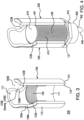
Figure 3 is a perspective partial cut-away view of the tubing retainer shown inFigure 1 , wherein the tubing retainer has been partially rotated from the view shown inFigure 1 . -
Figure 4 shows a sensor having an upper end having a sensor face, wherein at least the upper end has an outer surface with threads threadably engaged in the threads in the second end of the tubing retainer shown inFigure 3 . -
Figure 5 is a perspective view of a sensing system according to another aspect of the invention, showing the sensor threadably engaged in the second end of the tubing retainer as shown inFigure 4 , with cylindrical tubing retained in the first end of the tubing retainer, wherein a portion of the outer surface of the cylindrical tubing directly opposes the face of the sensor. -
Figure 6 is a perspective view of the sensing system as shown inFigure 5 attached to a mounting plate. - In accordance with an aspect of the invention, a tubing retainer for use with a sensor comprises (a) a hollow polymeric shaft having a first end, a second end, a side wall having a cylindrical inner surface and an outer surface, and a vertical axis; (i) the first end having cut outs through opposing portions of the side wall, the cut outs forming first and second slots in the opposing portions of the side wall, the first and second slots collectively arranged to receive cylindrical tubing therein, the first and second slots each having a narrower portion at the first end for initially receiving the cylindrical tubing, and a wider portion below the narrower portion, the wider portion providing a closed end of the slot, wherein the wider portion has an inner diameter arranged to retain the cylindrical tubing without significantly compressing the cylindrical tubing; (ii) the second end having threads on the inner surface, and a flat base perpendicular to the vertical axis.
- In another aspect, a sensing system is provided, comprising an aspect of the tubing retainer; cylindrical tubing retained in the first end of the tubing retainer; and, a sensor having an upper end and a lower end, the sensor having an outer surface including threads engageable with the threads on the inner surface of the second end of the tubing retainer.
- In another aspect, a method of retaining tubing is provided, the method comprising placing cylindrical tubing in a tubing retainer for use with a sensor, the tubing retainer comprising a hollow polymeric shaft having a first end, a second end, a side wall having a cylindrical inner surface and an outer surface, and a vertical axis; (i) the first end having cut outs through opposing portions of the side wall, the cut outs forming first and second slots in the opposing portions of the side wall, the first and second slots collectively arranged to receive cylindrical tubing therein, the first and second slots each having a narrower portion at the first end for initially receiving the cylindrical tubing, and a wider portion below the narrower portion, the wider portion providing a closed end of the slot, wherein the wider portion has an inner diameter arranged to retain the cylindrical tubing without significantly compressing the cylindrical tubing; (ii) the second end having threads on the inner surface, and a flat base perpendicular to the vertical axis; and, placing cylindrical tubing in the slots in the first end of the tubing retainer, and sliding the cylindrical tubing through the narrower portions into the wider portions. In an aspect, the method also includes threadably engaging a sensor in the second end of the aspect of the tubing retainer.
- Advantageously, particularly for applications involving single use tubing, that can require frequent installation and removal, and, when used in clean room by operators having double gloved hands, the tubing can be easily engaged in the tubing retainer, without an additional attachment or an element such as a lid. The distance between the tubing and the sensor is controlled, remaining the same, allowing consistent valid measurements to be carried out. Additionally, threads are not exposed in the clean room, and thread jamming during installation in the clean room can be avoided. Aspects of the tubing retainer can be easily manufactured.
- Each of the components of the invention will now be described in more detail below, wherein like components have like reference numbers.
- As shown in
Figures 1-3 (Figure 3 showing the tubing retainer rotated 45° in both the horizontal and rotational axes as compared toFigure 1 ), in one aspect, atubing retainer 200 for use with a sensor, comprises a hollowpolymeric shaft 100 having afirst end 101, asecond end 102 having a flat base 103, aside wall 110 having a cylindricalinner surface 111 and anouter surface 112, and a vertical axis "V"; the first end havingcorresponding cut outs opposing portions second slots 120A, 120B in the opposing portions of the side wall, the first and second slots collectively arranged to receive cylindrical tubing 600 (shown inFigures 5 and6 ) therein, the first and second slots each having anarrower portion 121A, 121B at the first end for initially receiving the cylindrical tubing, and awider portion ends inner diameter second end 102 havingthreads 130 on the cylindricalinner surface 111, and aflat base 131 perpendicular to the vertical axis. - The
second end 102 of the tubing retainer hasthreads 130 on at least of portion of theinner surface 111, extending toward the first end, approaching, if not reaching, the level of the closed ends of the slots. WhileFigures 2-6 show thethreads 130 extending over a portion of the inner surface of the second end, the threads can extend downwardly, toward, and in some aspects reaching, the flat base -
Figure 4 shows asensor 400 having anupper end 401 including aface 410, and a lower end 402 (and acable 440 extending from the lower end), the sensor having anouter surface 412 includingthreads 430 engageable with thethreads 130 on the inner surface of the second end of the tubing retainer. - As noted above and as shown in
Figures 4-6 , thethreads 130 on the inner surface of thesecond end 102 are configured to engage withthreads 430 on theouter surface 412 of asensor 400, wherein whencylindrical tubing 600 is retained in thefirst end 101 of thetubing retainer 200 and thesensor 400 is threadably engaged in thesecond end 102 of the tubing retainer, aportion 601 of the cylindrical tubing is aligned with theupper end 401 of the sensor, such that alower portion 601A of the tubing opposes (faces) theface 410 of the sensor. - The
inner diameter tubing 600 to hold the tubing in position. For example, the inner diameters of the wider portions can be about 5% smaller, or about 2% smaller than the outer diameter of the cylindrical tubing. Illustratively, if the outside diameter of the tubing is 90 mm, the inside diameters of the wider portions can be 90 mm or in the range of 88.2 mm to 88.8 mm. As will be recognized by one of skill in the art, the sizes of the slots, inner diameters, and wider portions can be selected for use with a variety of cylindrical tubing having different outside diameters. - In some aspects, the
lower portion 601A of the outer surface of thetubing 600 facing thesensor 400 contacts theface 410 of thesensor 400; in other aspects, there is a gap (e.g., about 2 cm or less; in some aspects, about 1 cm or less, for example, in the range of .2 cm to .6 cm) between the outer surface of the tubing (thelower portion 601A of the tubing retained in the closed end of the slot facing the sensor) and the face of the sensor. For example, theupper end 401 of the sensor can be screwed into thesecond end 102 of theretainer 200 until the desired contact or gap is achieved, or the threads in the second end of the retainer can end a desired distance from the bottom of the slots. - In another aspect,
Figures 5 and6 show anexemplary sensing system 1000 comprising an aspect of thetubing retainer 200;cylindrical tubing 600 retained in thefirst end 100 of the tubing retainer; and, thesensor 400 having anupper end 401 and alower end 402, the sensor having anouter surface 412 includingthreads 430 engageable with (shown engaged with) thethreads 130 on the inner surface of the second end of the tubing retainer. - A variety of sensors (which are non-invasive) are suitable for use in aspects of the invention, including magnetic (capacitive), ultrasonic, and optical, wherein at least the upper end of the sensor (the portion of the sensor inserted into the second (lower) end of the tubing retainer) has a cylindrical shape such that the external threads on the sensor are readily engageable with the threads on the inner surface of the second end of the tubing retainer.
- In some aspects, as illustrated in
Figure 6 , the upper end of the sensor passes through amounting plate 700 and a threadednut 415 can assist in retaining the sensor in position during use. If desired, a gasket can be arranged between the upper surface of the nut and the base of the retainer. In the aspect illustrated inFigure 6 ,gasket 731 is arranged between the base of the retainer and the top surface of the mounting plate. - The shaft can be fabricated from any suitable polymeric material, including any suitable thermoplastic polymeric material. Suitable polymers include, for example, silicon, or an acrylic, polypropylene, polystyrene, or a polycarbonated resin.
- Aspects of the invention are suitable for use in a variety of fluid processing systems, for example, as used with bioreactors, filtration systems, filling systems, and fluid handling systems.
- In an aspect, a method of retaining tubing comprises placing cylindrical tubing in the slots in the first end of an aspect of the tubing retainer, sliding the tubing through the narrower portions into the wider portions. Aspects of the method can also include threadably engaging a sensor in the second end of the aspect of the tubing retainer. If desired, the method can comprises engaging the sensor in the second end of the tubing retainer before placing tubing in the slots in the first end of the tubing retainer, or vice versa.
- If desired, aspects of the method can include placing the face of the sensor in contact with the cylindrical tubing, or providing a predetermined gap between the face of the sensor and the cylindrical tubing.
- In another aspect, a method for sensing a parameter of a fluid (liquid or air) in cylindrical tubing in an aspect of a sensing system comprises passing the fluid through the cylindrical tubing and receiving data regarding the parameter from the sensor.
- The following example further illustrates the invention but, of course, should not be construed as in any way limiting its scope.
- This example demonstrates a method of retaining tubing according to an aspect of the invention.
- A sensing system for use in a bioreactor is set up as generally shown in
Figure 5 , wherein a Rechner KAS-80-A14 capacitive sensor (Rechner Industrie-Elektronik Gmbh, Lampertheim, Germany) is threaded in the second end of the retainer. The outside diameter of the tubing is 90 mm, the inside diameter of the wider portions is about 88.5 mm, and the tubing is easily engaged in position. The lower portion of the tubing contacts the face of the sensor. - Protein solution is passed through the tubing, and a programmable logic controller shows a consistent measurement of the passage of the protein solution.
Claims (11)
- A tubing retainer for use with a sensor, comprising(a) a hollow polymeric shaft having a first end, a second end, a side wall having a cylindrical inner surface and an outer surface, and a vertical axis;(i) the first end having cut outs through opposing portions of the side wall, the cut outs forming first and second slots in the opposing portions of the side wall, the first and second slots collectively arranged to receive cylindrical tubing therein, the first and second slots each having a narrower portion at the first end for initially receiving the cylindrical tubing, and a wider portion below the narrower portion, the wider portion providing a closed end of the slot, wherein the wider portion has an inner diameter arranged to retain the cylindrical tubing without significantly compressing the cylindrical tubing;(ii) the second end having threads on the inner surface, and a flat base perpendicular to the vertical axis.
- The tubing retainer of claim 1, wherein the threads on the inner surface of the second end are configured to engage with threads on an outer surface of a sensor;
wherein when cylindrical tubing is retained in the first end of the tubing retainer and the sensor is threadably engaged in the second end of the tubing retainer, the cylindrical tubing is aligned with an upper end of a sensor. - The tubing retainer of claim 1 or 2, wherein the inner diameter of the wider portion is equal to an outer diameter of the cylindrical tubing.
- The tubing retainer of claim 1 or 2, wherein the inner diameter of the wider portion is about 5% smaller than an outer diameter of the cylindrical tubing.
- The tubing retainer of any one of claims 1-4, wherein when the cylindrical tubing is retained in the first end of the tubing retainer and the sensor is threadably engaged in the second end of the tubing retainer, a distance from the closed ends of the first and second slots to an upper end of the sensor is about 2 cm or less.
- The tubing retainer of claim 5, wherein when the cylindrical tubing is retained in the first end of the tubing retainer and the sensor is threadably engaged in the second end of the tubing retainer, the top end of the sensor contacts an outer surface of the cylindrical tubing.
- A sensing system comprising the tubing retainer of any one of claims 1-6;cylindrical tubing retained in the first end of the tubing retainer; and,a sensor having an upper end and a lower end, the sensor having an outer surface including threads engageable with the threads on the inner surface of the second end of the tubing retainer.
- The sensing system of claim 7, wherein the sensor comprises an ultrasonic sensor.
- The sensing system of claim 7, wherein the sensor comprises a capacitive sensor.
- A method of retaining cylindrical tubing, the method comprising placing cylindrical tubing in a tubing retainer for use with a sensor, the tubing retainer comprisinga hollow polymeric shaft having a first end, a second end, a side wall having a cylindrical inner surface and an outer surface, and a vertical axis;(i) the first end having cut outs through opposing portions of the side wall, the cut outs forming first and second slots in the opposing portions of the side wall, the first and second slots collectively arranged to receive cylindrical tubing therein, the first and second slots each having a narrower portion at the first end for initially receiving the cylindrical tubing, and a wider portion below the narrower portion, the wider portion providing a closed end of the slot, wherein the wider portion has an inner diameter arranged to retain the cylindrical tubing without significantly compressing the cylindrical tubing;(ii) the second end having threads on the inner surface, and a flat base perpendicular to the vertical axis; and,placing cylindrical tubing in the slots in the first end of the tubing retainer, and sliding the cylindrical tubing through the narrower portions into the wider portions.
- The method of claim 10, also including threadably engaging a sensor in the second end of the aspect of the tubing retainer.
Applications Claiming Priority (1)
| Application Number | Priority Date | Filing Date | Title |
|---|---|---|---|
| US17/387,487 US11754201B2 (en) | 2021-07-28 | 2021-07-28 | Tubing retainer |
Publications (2)
| Publication Number | Publication Date |
|---|---|
| EP4124835A1 true EP4124835A1 (en) | 2023-02-01 |
| EP4124835B1 EP4124835B1 (en) | 2024-04-24 |
Family
ID=82308602
Family Applications (1)
| Application Number | Title | Priority Date | Filing Date |
|---|---|---|---|
| EP22180996.5A Active EP4124835B1 (en) | 2021-07-28 | 2022-06-24 | Tubing retainer |
Country Status (7)
| Country | Link |
|---|---|
| US (1) | US11754201B2 (en) |
| EP (1) | EP4124835B1 (en) |
| JP (1) | JP7396599B2 (en) |
| KR (1) | KR102831855B1 (en) |
| CN (1) | CN115681634B (en) |
| ES (1) | ES2978772T3 (en) |
| PL (1) | PL4124835T3 (en) |
Citations (3)
| Publication number | Priority date | Publication date | Assignee | Title |
|---|---|---|---|---|
| AU468111B2 (en) * | 1971-06-23 | 1976-01-08 | Hector Sutherland Donald | Tool for tapping asbestos cement water mains |
| GB2276925A (en) * | 1991-01-21 | 1994-10-12 | British Gas Plc | Pipe-tapping |
| US5694972A (en) * | 1996-06-27 | 1997-12-09 | Tom King Harmony Products, Inc. | Saddle tee for irrigation lines |
Family Cites Families (34)
| Publication number | Priority date | Publication date | Assignee | Title |
|---|---|---|---|---|
| US3747166A (en) | 1971-05-21 | 1973-07-24 | Instrumentation Industries | Hose holder |
| US4062574A (en) * | 1976-10-05 | 1977-12-13 | Scholin Industries, Inc. | Fitting assembly |
| FR2414165A1 (en) | 1978-01-06 | 1979-08-03 | Irizar Otegui Joaquina | Plastics clip for supporting pipe - has cylindrical recess to hold pipe with snap action and retainer cap received in diametrically opposite slots |
| US4437691A (en) * | 1981-06-01 | 1984-03-20 | Laney Ralph M | Connector for corrugated tubing |
| NL8201862A (en) * | 1982-05-06 | 1983-12-01 | Erico Europa | DENTAL BRACES. |
| US4539849A (en) * | 1983-09-16 | 1985-09-10 | American Hospital Supply Corporation | Transducer assembly including a disposable dome |
| US5178354A (en) | 1990-07-25 | 1993-01-12 | Engvall David P | Tube holder and method of using the same |
| JPH0577359U (en) * | 1992-03-31 | 1993-10-22 | 株式会社クボタ | Unit bath pipe receiver |
| JP3006378U (en) | 1994-04-26 | 1995-01-24 | 株式会社タカショー | Connection tools such as round pipes |
| KR0143278B1 (en) * | 1995-08-18 | 1998-08-17 | 배순훈 | Internal gas generation detection device of battery |
| US6206613B1 (en) * | 1997-06-06 | 2001-03-27 | Michael L. Elkins | Configurable support apparatus for flexible pipe and method |
| JP4111389B2 (en) | 2003-02-12 | 2008-07-02 | 愛知時計電機株式会社 | Electromagnetic flow sensor and its mounting method |
| US7055868B2 (en) * | 2004-07-09 | 2006-06-06 | Highlands Corporation | Corrugated tube fitting |
| DE102007049367A1 (en) * | 2007-10-08 | 2009-04-09 | Thomas Grbesic | metering |
| DE102008054884A1 (en) * | 2008-12-18 | 2010-07-01 | Endress + Hauser Conducta Gesellschaft für Mess- und Regeltechnik mbH + Co. KG | Alternate alarm for a sensor |
| US9435630B2 (en) | 2010-12-08 | 2016-09-06 | Cts Corporation | Actuator and linear position sensor assembly |
| KR20120092330A (en) | 2011-02-11 | 2012-08-21 | (주)대교에이스 | Hose holder for tubing |
| CN202074123U (en) | 2011-04-26 | 2011-12-14 | 博世汽车部件(苏州)有限公司 | Cable-fixing device for fixing cable onto basal body |
| KR20130077512A (en) * | 2011-12-29 | 2013-07-09 | 레시너코리아 주식회사 | Capacitive type digital sensor for detecting liquid level |
| US9329061B2 (en) | 2013-02-28 | 2016-05-03 | Rosemount Inc. | Reduced-stress coupling for industrial process transmitter housing |
| US20150107379A1 (en) * | 2013-10-22 | 2015-04-23 | Therm-O-Disc, Incorporated | Flow sensor mounting apparatus |
| US20150211669A1 (en) | 2014-01-28 | 2015-07-30 | Philippe Van Houtte | Fixing device for spoke sensor |
| FR3018893B1 (en) * | 2014-03-20 | 2016-03-11 | Airbus Operations Sas | FIXING SYSTEM OF AT LEAST TWO PIPES |
| JP6673636B2 (en) * | 2014-11-27 | 2020-03-25 | パナソニック デバイスSunx株式会社 | Liquid sensor assembly method |
| US10774951B2 (en) * | 2017-11-16 | 2020-09-15 | Wcm Industries, Inc. | Pipe support system and method |
| EP3550291A1 (en) * | 2018-04-05 | 2019-10-09 | Georg Fischer Rohrleitungssysteme AG | Fastening device for measuring devices on pipes |
| JP6611141B1 (en) | 2018-07-12 | 2019-11-27 | 株式会社ピュアロンジャパン | Dissolved gas monitor clamp |
| JP2021063794A (en) | 2019-10-11 | 2021-04-22 | 株式会社industria | Clamp type holder, fine matter amount detection device, centrifugal separator, and fine matter removal system |
| WO2020246162A1 (en) | 2019-06-03 | 2020-12-10 | 株式会社industria | Fine material amount detection device, clamp-type holder, centrifugal separation device, and fine material removal system |
| JP6733980B1 (en) | 2019-12-06 | 2020-08-05 | 株式会社新光工業 | Vertical non-axis screw conveyor |
| CN212929000U (en) | 2020-03-26 | 2021-04-09 | 林建廷 | Reducing pipe clamp structure |
| CN212986251U (en) * | 2020-07-07 | 2021-04-16 | 岳中志 | A pipeline for hydraulic engineering |
| US11774022B2 (en) * | 2020-12-03 | 2023-10-03 | Mueller International, Llc | Pipe fitting with grip ring |
| JP7602968B2 (en) | 2021-05-31 | 2024-12-19 | 株式会社三五 | Joining structure and joining method |
-
2021
- 2021-07-28 US US17/387,487 patent/US11754201B2/en active Active
-
2022
- 2022-06-24 ES ES22180996T patent/ES2978772T3/en active Active
- 2022-06-24 EP EP22180996.5A patent/EP4124835B1/en active Active
- 2022-06-24 PL PL22180996.5T patent/PL4124835T3/en unknown
- 2022-06-28 JP JP2022103758A patent/JP7396599B2/en active Active
- 2022-07-19 KR KR1020220089223A patent/KR102831855B1/en active Active
- 2022-07-27 CN CN202210889016.7A patent/CN115681634B/en active Active
Patent Citations (3)
| Publication number | Priority date | Publication date | Assignee | Title |
|---|---|---|---|---|
| AU468111B2 (en) * | 1971-06-23 | 1976-01-08 | Hector Sutherland Donald | Tool for tapping asbestos cement water mains |
| GB2276925A (en) * | 1991-01-21 | 1994-10-12 | British Gas Plc | Pipe-tapping |
| US5694972A (en) * | 1996-06-27 | 1997-12-09 | Tom King Harmony Products, Inc. | Saddle tee for irrigation lines |
Also Published As
| Publication number | Publication date |
|---|---|
| ES2978772T3 (en) | 2024-09-19 |
| CN115681634B (en) | 2026-04-10 |
| JP7396599B2 (en) | 2023-12-12 |
| KR20230017737A (en) | 2023-02-06 |
| JP2023020920A (en) | 2023-02-09 |
| US11754201B2 (en) | 2023-09-12 |
| PL4124835T3 (en) | 2024-09-09 |
| US20230030395A1 (en) | 2023-02-02 |
| CN115681634A (en) | 2023-02-03 |
| EP4124835B1 (en) | 2024-04-24 |
| KR102831855B1 (en) | 2025-07-10 |
Similar Documents
| Publication | Publication Date | Title |
|---|---|---|
| CA1187756A (en) | Injection site | |
| EP0257339B1 (en) | Medical micro pipette tips for difficult to reach places and related methods | |
| US5223225A (en) | Scale-marked pipet tip for precision dispensing of fluids over a large range of volumes | |
| US5032343A (en) | Method for producing medical micro pipette tips for difficult to reach places | |
| EP1406492B1 (en) | Centrifuge tube assembly | |
| US4721680A (en) | Methods of using micro pipette tips | |
| EP0901820B1 (en) | Collection container assembly | |
| US20250186991A1 (en) | Pipette for use with a pipette tip and pipette tip line comprising several pipette tips of different types for use with a pipette | |
| AU1041883A (en) | Injection site | |
| CA3021200C (en) | Container gripper assembly | |
| EP0901817B1 (en) | Collection container assembly | |
| EP4124835B1 (en) | Tubing retainer | |
| GB2085603A (en) | Medicament Reservoir | |
| US9291529B2 (en) | Syringe for use with a metering device | |
| KR20160010112A (en) | Security connector having vial changing check function and medical solution product with the connector | |
| EP0732973B1 (en) | A method for collecting small quantities of liquid samples and sample containers for collecting small liquid quantities | |
| US20140117027A1 (en) | Container with aggregating feature | |
| EP2412440A1 (en) | System and method for dispensing fluid from a container and into a fluid receptacle | |
| EP0992767A1 (en) | Variable height sensor tree | |
| US20220372746A1 (en) | Sewer cleanout cap and methods | |
| US11191698B2 (en) | Apparatus and method for processing platelet rich fibrin | |
| CN210097734U (en) | Experimental sample collecting device | |
| WO2019077448A1 (en) | Container for carrying out medical or veterinary procedures and related calibration method | |
| AU634468B2 (en) | Medical fail safe releasible locks and/or seals for capped disposable centrifuge containers, cryogenic vials and the like | |
| EP3283199A1 (en) | Vacuum filtration system |
Legal Events
| Date | Code | Title | Description |
|---|---|---|---|
| PUAI | Public reference made under article 153(3) epc to a published international application that has entered the european phase |
Free format text: ORIGINAL CODE: 0009012 |
|
| STAA | Information on the status of an ep patent application or granted ep patent |
Free format text: STATUS: THE APPLICATION HAS BEEN PUBLISHED |
|
| AK | Designated contracting states |
Kind code of ref document: A1 Designated state(s): AL AT BE BG CH CY CZ DE DK EE ES FI FR GB GR HR HU IE IS IT LI LT LU LV MC MK MT NL NO PL PT RO RS SE SI SK SM TR |
|
| P01 | Opt-out of the competence of the unified patent court (upc) registered |
Effective date: 20230530 |
|
| STAA | Information on the status of an ep patent application or granted ep patent |
Free format text: STATUS: REQUEST FOR EXAMINATION WAS MADE |
|
| 17P | Request for examination filed |
Effective date: 20230726 |
|
| RBV | Designated contracting states (corrected) |
Designated state(s): AL AT BE BG CH CY CZ DE DK EE ES FI FR GB GR HR HU IE IS IT LI LT LU LV MC MK MT NL NO PL PT RO RS SE SI SK SM TR |
|
| REG | Reference to a national code |
Ref country code: DE Ref legal event code: R079 Free format text: PREVIOUS MAIN CLASS: G01D0011240000 Ipc: G01D0011300000 Ref country code: DE Ref legal event code: R079 Ref document number: 602022003021 Country of ref document: DE Free format text: PREVIOUS MAIN CLASS: G01D0011240000 Ipc: G01D0011300000 |
|
| GRAP | Despatch of communication of intention to grant a patent |
Free format text: ORIGINAL CODE: EPIDOSNIGR1 |
|
| STAA | Information on the status of an ep patent application or granted ep patent |
Free format text: STATUS: GRANT OF PATENT IS INTENDED |
|
| RIC1 | Information provided on ipc code assigned before grant |
Ipc: F16L 41/00 20060101ALI20231120BHEP Ipc: G01D 11/30 20060101AFI20231120BHEP |
|
| INTG | Intention to grant announced |
Effective date: 20231206 |
|
| GRAS | Grant fee paid |
Free format text: ORIGINAL CODE: EPIDOSNIGR3 |
|
| GRAA | (expected) grant |
Free format text: ORIGINAL CODE: 0009210 |
|
| STAA | Information on the status of an ep patent application or granted ep patent |
Free format text: STATUS: THE PATENT HAS BEEN GRANTED |
|
| AK | Designated contracting states |
Kind code of ref document: B1 Designated state(s): AL AT BE BG CH CY CZ DE DK EE ES FI FR GB GR HR HU IE IS IT LI LT LU LV MC MK MT NL NO PL PT RO RS SE SI SK SM TR |
|
| REG | Reference to a national code |
Ref country code: GB Ref legal event code: FG4D |
|
| REG | Reference to a national code |
Ref country code: CH Ref legal event code: EP |
|
| REG | Reference to a national code |
Ref country code: DE Ref legal event code: R096 Ref document number: 602022003021 Country of ref document: DE |
|
| REG | Reference to a national code |
Ref country code: IE Ref legal event code: FG4D |
|
| REG | Reference to a national code |
Ref country code: SE Ref legal event code: TRGR |
|
| REG | Reference to a national code |
Ref country code: NL Ref legal event code: FP |
|
| REG | Reference to a national code |
Ref country code: LT Ref legal event code: MG9D |
|
| REG | Reference to a national code |
Ref country code: AT Ref legal event code: MK05 Ref document number: 1680043 Country of ref document: AT Kind code of ref document: T Effective date: 20240424 |
|
| PG25 | Lapsed in a contracting state [announced via postgrant information from national office to epo] |
Ref country code: IS Free format text: LAPSE BECAUSE OF FAILURE TO SUBMIT A TRANSLATION OF THE DESCRIPTION OR TO PAY THE FEE WITHIN THE PRESCRIBED TIME-LIMIT Effective date: 20240824 |
|
| PG25 | Lapsed in a contracting state [announced via postgrant information from national office to epo] |
Ref country code: BG Free format text: LAPSE BECAUSE OF FAILURE TO SUBMIT A TRANSLATION OF THE DESCRIPTION OR TO PAY THE FEE WITHIN THE PRESCRIBED TIME-LIMIT Effective date: 20240424 |
|
| PG25 | Lapsed in a contracting state [announced via postgrant information from national office to epo] |
Ref country code: HR Free format text: LAPSE BECAUSE OF FAILURE TO SUBMIT A TRANSLATION OF THE DESCRIPTION OR TO PAY THE FEE WITHIN THE PRESCRIBED TIME-LIMIT Effective date: 20240424 Ref country code: FI Free format text: LAPSE BECAUSE OF FAILURE TO SUBMIT A TRANSLATION OF THE DESCRIPTION OR TO PAY THE FEE WITHIN THE PRESCRIBED TIME-LIMIT Effective date: 20240424 |
|
| PG25 | Lapsed in a contracting state [announced via postgrant information from national office to epo] |
Ref country code: GR Free format text: LAPSE BECAUSE OF FAILURE TO SUBMIT A TRANSLATION OF THE DESCRIPTION OR TO PAY THE FEE WITHIN THE PRESCRIBED TIME-LIMIT Effective date: 20240725 |
|
| PG25 | Lapsed in a contracting state [announced via postgrant information from national office to epo] |
Ref country code: PT Free format text: LAPSE BECAUSE OF FAILURE TO SUBMIT A TRANSLATION OF THE DESCRIPTION OR TO PAY THE FEE WITHIN THE PRESCRIBED TIME-LIMIT Effective date: 20240826 |
|
| PG25 | Lapsed in a contracting state [announced via postgrant information from national office to epo] |
Ref country code: AT Free format text: LAPSE BECAUSE OF FAILURE TO SUBMIT A TRANSLATION OF THE DESCRIPTION OR TO PAY THE FEE WITHIN THE PRESCRIBED TIME-LIMIT Effective date: 20240424 |
|
| PG25 | Lapsed in a contracting state [announced via postgrant information from national office to epo] |
Ref country code: LV Free format text: LAPSE BECAUSE OF FAILURE TO SUBMIT A TRANSLATION OF THE DESCRIPTION OR TO PAY THE FEE WITHIN THE PRESCRIBED TIME-LIMIT Effective date: 20240424 |
|
| PG25 | Lapsed in a contracting state [announced via postgrant information from national office to epo] |
Ref country code: PT Free format text: LAPSE BECAUSE OF FAILURE TO SUBMIT A TRANSLATION OF THE DESCRIPTION OR TO PAY THE FEE WITHIN THE PRESCRIBED TIME-LIMIT Effective date: 20240826 Ref country code: NO Free format text: LAPSE BECAUSE OF FAILURE TO SUBMIT A TRANSLATION OF THE DESCRIPTION OR TO PAY THE FEE WITHIN THE PRESCRIBED TIME-LIMIT Effective date: 20240724 Ref country code: LV Free format text: LAPSE BECAUSE OF FAILURE TO SUBMIT A TRANSLATION OF THE DESCRIPTION OR TO PAY THE FEE WITHIN THE PRESCRIBED TIME-LIMIT Effective date: 20240424 Ref country code: IS Free format text: LAPSE BECAUSE OF FAILURE TO SUBMIT A TRANSLATION OF THE DESCRIPTION OR TO PAY THE FEE WITHIN THE PRESCRIBED TIME-LIMIT Effective date: 20240824 Ref country code: HR Free format text: LAPSE BECAUSE OF FAILURE TO SUBMIT A TRANSLATION OF THE DESCRIPTION OR TO PAY THE FEE WITHIN THE PRESCRIBED TIME-LIMIT Effective date: 20240424 Ref country code: GR Free format text: LAPSE BECAUSE OF FAILURE TO SUBMIT A TRANSLATION OF THE DESCRIPTION OR TO PAY THE FEE WITHIN THE PRESCRIBED TIME-LIMIT Effective date: 20240725 Ref country code: FI Free format text: LAPSE BECAUSE OF FAILURE TO SUBMIT A TRANSLATION OF THE DESCRIPTION OR TO PAY THE FEE WITHIN THE PRESCRIBED TIME-LIMIT Effective date: 20240424 Ref country code: BG Free format text: LAPSE BECAUSE OF FAILURE TO SUBMIT A TRANSLATION OF THE DESCRIPTION OR TO PAY THE FEE WITHIN THE PRESCRIBED TIME-LIMIT Effective date: 20240424 Ref country code: AT Free format text: LAPSE BECAUSE OF FAILURE TO SUBMIT A TRANSLATION OF THE DESCRIPTION OR TO PAY THE FEE WITHIN THE PRESCRIBED TIME-LIMIT Effective date: 20240424 Ref country code: RS Free format text: LAPSE BECAUSE OF FAILURE TO SUBMIT A TRANSLATION OF THE DESCRIPTION OR TO PAY THE FEE WITHIN THE PRESCRIBED TIME-LIMIT Effective date: 20240724 |
|
| PG25 | Lapsed in a contracting state [announced via postgrant information from national office to epo] |
Ref country code: DK Free format text: LAPSE BECAUSE OF FAILURE TO SUBMIT A TRANSLATION OF THE DESCRIPTION OR TO PAY THE FEE WITHIN THE PRESCRIBED TIME-LIMIT Effective date: 20240424 |
|
| PG25 | Lapsed in a contracting state [announced via postgrant information from national office to epo] |
Ref country code: EE Free format text: LAPSE BECAUSE OF FAILURE TO SUBMIT A TRANSLATION OF THE DESCRIPTION OR TO PAY THE FEE WITHIN THE PRESCRIBED TIME-LIMIT Effective date: 20240424 |
|
| PG25 | Lapsed in a contracting state [announced via postgrant information from national office to epo] |
Ref country code: CZ Free format text: LAPSE BECAUSE OF FAILURE TO SUBMIT A TRANSLATION OF THE DESCRIPTION OR TO PAY THE FEE WITHIN THE PRESCRIBED TIME-LIMIT Effective date: 20240424 |
|
| PG25 | Lapsed in a contracting state [announced via postgrant information from national office to epo] |
Ref country code: RO Free format text: LAPSE BECAUSE OF FAILURE TO SUBMIT A TRANSLATION OF THE DESCRIPTION OR TO PAY THE FEE WITHIN THE PRESCRIBED TIME-LIMIT Effective date: 20240424 Ref country code: SK Free format text: LAPSE BECAUSE OF FAILURE TO SUBMIT A TRANSLATION OF THE DESCRIPTION OR TO PAY THE FEE WITHIN THE PRESCRIBED TIME-LIMIT Effective date: 20240424 |
|
| REG | Reference to a national code |
Ref country code: DE Ref legal event code: R097 Ref document number: 602022003021 Country of ref document: DE |
|
| PG25 | Lapsed in a contracting state [announced via postgrant information from national office to epo] |
Ref country code: SM Free format text: LAPSE BECAUSE OF FAILURE TO SUBMIT A TRANSLATION OF THE DESCRIPTION OR TO PAY THE FEE WITHIN THE PRESCRIBED TIME-LIMIT Effective date: 20240424 |
|
| PG25 | Lapsed in a contracting state [announced via postgrant information from national office to epo] |
Ref country code: SM Free format text: LAPSE BECAUSE OF FAILURE TO SUBMIT A TRANSLATION OF THE DESCRIPTION OR TO PAY THE FEE WITHIN THE PRESCRIBED TIME-LIMIT Effective date: 20240424 Ref country code: SK Free format text: LAPSE BECAUSE OF FAILURE TO SUBMIT A TRANSLATION OF THE DESCRIPTION OR TO PAY THE FEE WITHIN THE PRESCRIBED TIME-LIMIT Effective date: 20240424 Ref country code: RO Free format text: LAPSE BECAUSE OF FAILURE TO SUBMIT A TRANSLATION OF THE DESCRIPTION OR TO PAY THE FEE WITHIN THE PRESCRIBED TIME-LIMIT Effective date: 20240424 Ref country code: EE Free format text: LAPSE BECAUSE OF FAILURE TO SUBMIT A TRANSLATION OF THE DESCRIPTION OR TO PAY THE FEE WITHIN THE PRESCRIBED TIME-LIMIT Effective date: 20240424 Ref country code: DK Free format text: LAPSE BECAUSE OF FAILURE TO SUBMIT A TRANSLATION OF THE DESCRIPTION OR TO PAY THE FEE WITHIN THE PRESCRIBED TIME-LIMIT Effective date: 20240424 Ref country code: CZ Free format text: LAPSE BECAUSE OF FAILURE TO SUBMIT A TRANSLATION OF THE DESCRIPTION OR TO PAY THE FEE WITHIN THE PRESCRIBED TIME-LIMIT Effective date: 20240424 Ref country code: MC Free format text: LAPSE BECAUSE OF FAILURE TO SUBMIT A TRANSLATION OF THE DESCRIPTION OR TO PAY THE FEE WITHIN THE PRESCRIBED TIME-LIMIT Effective date: 20240424 |
|
| PG25 | Lapsed in a contracting state [announced via postgrant information from national office to epo] |
Ref country code: LU Free format text: LAPSE BECAUSE OF NON-PAYMENT OF DUE FEES Effective date: 20240624 |
|
| PLBE | No opposition filed within time limit |
Free format text: ORIGINAL CODE: 0009261 |
|
| STAA | Information on the status of an ep patent application or granted ep patent |
Free format text: STATUS: NO OPPOSITION FILED WITHIN TIME LIMIT |
|
| 26N | No opposition filed |
Effective date: 20250127 |
|
| PG25 | Lapsed in a contracting state [announced via postgrant information from national office to epo] |
Ref country code: IE Free format text: LAPSE BECAUSE OF NON-PAYMENT OF DUE FEES Effective date: 20240624 |
|
| PG25 | Lapsed in a contracting state [announced via postgrant information from national office to epo] |
Ref country code: SI Free format text: LAPSE BECAUSE OF FAILURE TO SUBMIT A TRANSLATION OF THE DESCRIPTION OR TO PAY THE FEE WITHIN THE PRESCRIBED TIME-LIMIT Effective date: 20240424 Ref country code: BE Free format text: LAPSE BECAUSE OF NON-PAYMENT OF DUE FEES Effective date: 20240630 |
|
| REG | Reference to a national code |
Ref country code: BE Ref legal event code: MM Effective date: 20240630 |
|
| PGFP | Annual fee paid to national office [announced via postgrant information from national office to epo] |
Ref country code: PL Payment date: 20250603 Year of fee payment: 4 Ref country code: DE Payment date: 20250626 Year of fee payment: 4 |
|
| PGFP | Annual fee paid to national office [announced via postgrant information from national office to epo] |
Ref country code: NL Payment date: 20250624 Year of fee payment: 4 |
|
| PGFP | Annual fee paid to national office [announced via postgrant information from national office to epo] |
Ref country code: FR Payment date: 20250624 Year of fee payment: 4 |
|
| PGFP | Annual fee paid to national office [announced via postgrant information from national office to epo] |
Ref country code: SE Payment date: 20250619 Year of fee payment: 4 |
|
| PGFP | Annual fee paid to national office [announced via postgrant information from national office to epo] |
Ref country code: ES Payment date: 20250710 Year of fee payment: 4 |
|
| PG25 | Lapsed in a contracting state [announced via postgrant information from national office to epo] |
Ref country code: CY Free format text: LAPSE BECAUSE OF FAILURE TO SUBMIT A TRANSLATION OF THE DESCRIPTION OR TO PAY THE FEE WITHIN THE PRESCRIBED TIME-LIMIT; INVALID AB INITIO Effective date: 20220624 |
|
| PGFP | Annual fee paid to national office [announced via postgrant information from national office to epo] |
Ref country code: IT Payment date: 20250630 Year of fee payment: 4 |
|
| PG25 | Lapsed in a contracting state [announced via postgrant information from national office to epo] |
Ref country code: IT Free format text: LAPSE BECAUSE OF NON-PAYMENT OF DUE FEES Effective date: 20240624 |
|
| REG | Reference to a national code |
Ref country code: CH Ref legal event code: H13 Free format text: ST27 STATUS EVENT CODE: U-0-0-H10-H13 (AS PROVIDED BY THE NATIONAL OFFICE) Effective date: 20260127 |
|
| PG25 | Lapsed in a contracting state [announced via postgrant information from national office to epo] |
Ref country code: HU Free format text: LAPSE BECAUSE OF FAILURE TO SUBMIT A TRANSLATION OF THE DESCRIPTION OR TO PAY THE FEE WITHIN THE PRESCRIBED TIME-LIMIT; INVALID AB INITIO Effective date: 20220624 |
|
| PG25 | Lapsed in a contracting state [announced via postgrant information from national office to epo] |
Ref country code: IT Free format text: LAPSE BECAUSE OF NON-PAYMENT OF DUE FEES Effective date: 20240624 |
|
| PGRI | Patent reinstated in contracting state [announced from national office to epo] |
Ref country code: IT Effective date: 20240701 |
|
| PG25 | Lapsed in a contracting state [announced via postgrant information from national office to epo] |
Ref country code: CH Free format text: LAPSE BECAUSE OF NON-PAYMENT OF DUE FEES Effective date: 20250630 |