EP4124575B1 - Ensemble propulsif pour aéronef comportant un turboréacteur, un mât et des moyens d accrochage du turboréacteur au mât - Google Patents
Ensemble propulsif pour aéronef comportant un turboréacteur, un mât et des moyens d accrochage du turboréacteur au mât Download PDFInfo
- Publication number
- EP4124575B1 EP4124575B1 EP22186620.5A EP22186620A EP4124575B1 EP 4124575 B1 EP4124575 B1 EP 4124575B1 EP 22186620 A EP22186620 A EP 22186620A EP 4124575 B1 EP4124575 B1 EP 4124575B1
- Authority
- EP
- European Patent Office
- Prior art keywords
- fitting
- rigid structure
- turbojet
- central
- mast
- Prior art date
- Legal status (The legal status is an assumption and is not a legal conclusion. Google has not performed a legal analysis and makes no representation as to the accuracy of the status listed.)
- Active
Links
Images

Classifications
-
- F—MECHANICAL ENGINEERING; LIGHTING; HEATING; WEAPONS; BLASTING
- F02—COMBUSTION ENGINES; HOT-GAS OR COMBUSTION-PRODUCT ENGINE PLANTS
- F02C—GAS-TURBINE PLANTS; AIR INTAKES FOR JET-PROPULSION PLANTS; CONTROLLING FUEL SUPPLY IN AIR-BREATHING JET-PROPULSION PLANTS
- F02C7/00—Features, components parts, details or accessories, not provided for in, or of interest apart form groups F02C1/00 - F02C6/00; Air intakes for jet-propulsion plants
- F02C7/20—Mounting or supporting of plant; Accommodating heat expansion or creep
-
- B—PERFORMING OPERATIONS; TRANSPORTING
- B64—AIRCRAFT; AVIATION; COSMONAUTICS
- B64D—EQUIPMENT FOR FITTING IN OR TO AIRCRAFT; FLIGHT SUITS; PARACHUTES; ARRANGEMENT OR MOUNTING OF POWER PLANTS OR PROPULSION TRANSMISSIONS IN AIRCRAFT
- B64D27/00—Arrangement or mounting of power plants in aircraft; Aircraft characterised by the type or position of power plants
- B64D27/02—Aircraft characterised by the type or position of power plants
- B64D27/16—Aircraft characterised by the type or position of power plants of jet type
- B64D27/18—Aircraft characterised by the type or position of power plants of jet type within, or attached to, wings
-
- B—PERFORMING OPERATIONS; TRANSPORTING
- B64—AIRCRAFT; AVIATION; COSMONAUTICS
- B64D—EQUIPMENT FOR FITTING IN OR TO AIRCRAFT; FLIGHT SUITS; PARACHUTES; ARRANGEMENT OR MOUNTING OF POWER PLANTS OR PROPULSION TRANSMISSIONS IN AIRCRAFT
- B64D27/00—Arrangement or mounting of power plants in aircraft; Aircraft characterised by the type or position of power plants
- B64D27/40—Arrangements for mounting power plants in aircraft
- B64D27/404—Suspension arrangements specially adapted for supporting vertical loads
-
- B—PERFORMING OPERATIONS; TRANSPORTING
- B64—AIRCRAFT; AVIATION; COSMONAUTICS
- B64D—EQUIPMENT FOR FITTING IN OR TO AIRCRAFT; FLIGHT SUITS; PARACHUTES; ARRANGEMENT OR MOUNTING OF POWER PLANTS OR PROPULSION TRANSMISSIONS IN AIRCRAFT
- B64D27/00—Arrangement or mounting of power plants in aircraft; Aircraft characterised by the type or position of power plants
- B64D27/40—Arrangements for mounting power plants in aircraft
- B64D27/406—Suspension arrangements specially adapted for supporting thrust loads, e.g. thrust links
Definitions
- the present invention relates to the general field of attaching a turbojet under the wing of an aircraft. It relates in particular to a propulsion assembly comprising a turbojet, in particular a turbojet, a mast as well as a hooking device intended for hooking the turbojet under the mast. It also relates to an aircraft equipped with such a propulsion assembly.
- a propulsion assembly of the state of the art is fixed under a wing of an aircraft which comprises a turbojet and a mounting mast via which the turbojet is fixed under the wing.
- the attachment mast comprises a rigid structure, also called primary structure, carrying first fixing elements intended for attaching the turbojet.
- These first fixing elements are formed of a front engine mount, a rear engine mount, and a device for absorbing the thrust forces generated by the turbojet.
- the attachment mast further comprises second fixing elements allowing the attachment of the attachment mast to the wing.
- the turbojet has at the front a fan casing surrounding an annular fan channel, and towards the rear a smaller central casing, enclosing the core of the turbojet.
- the front engine attachment is interposed between a front end of the rigid structure and an upper and front part of the central casing and the rear engine attachment is interposed between the rigid structure and an upper and rear part of the central casing.
- the device for absorbing the thrust forces generated by the turbojet engine comprises two connecting rods arranged on either side of a median vertical plane of the turbojet engine and articulated, on the one hand, on the central casing, and, on the other hand, on a single spreader fixed to the rigid structure.
- the device for taking up the thrust forces formed by the two connecting rods and the rudder is designed to take up all or the majority of the forces oriented in the longitudinal direction X of the turbojet.
- the front engine attachment has a connecting rod on either side of the mast and each connecting rod is hingedly fixed by one of its ends to the mast and is hingedly fixed by the other of its ends to the central casing.
- One of the connecting rods is fixed by two connection points to the mast and by a connection point to the central casing, and the second connecting rod is fixed by a connection point to the mast and by a connection point to the central casing.
- the front engine mount makes it possible to take up part of the forces oriented in the Y and Z directions as well as a torque Mx.
- the rear engine mount also makes it possible to take up part of the forces directed in the Y and Z directions.
- An object of the present invention is to propose a propulsion assembly comprising a turbojet, a mast and a hooking device intended for hooking the turbojet under the mast, and which allows a different redistribution of force recovery.
- the invention also proposes an aircraft comprising a wing and a propulsion assembly according to the previous variant, the rigid structure of which is fixed under the wing.
- FIG. 1 shows an aircraft 50 which has a wing 52 under which is mounted a propulsion assembly 100 which comprises a turbojet 102 and a mounting mast 104.
- turbojet 102 the longitudinal direction of turbojet 102, this direction X being parallel to a longitudinal axis of this turbojet 102.
- Y the transverse direction of turbojet 102 which is horizontal when the aircraft is at ground
- Z the vertical direction or vertical height when the aircraft is on the ground, these three directions X, Y and Z being orthogonal to each other.
- FIG. 2 shows the propulsion assembly 100 which comprises the turbojet 102 and the attachment mast 104 by which the turbojet 102 is fixed to the wing 52.
- the attachment mast 104 is here represented by its rigid structure 106, also called primary structure, carrying first fixing elements 150 intended for attaching the turbojet 102.
- the rigid structure 106 extends in the longitudinal direction X between a front end and a rear end between which there is a middle zone.
- the rigid structure 106 takes the form of a box which comprises a lower wall 106a, an upper wall 106b, two side walls 106c and a front wall 106d.
- These first fixing elements are formed of a front engine mount 152, a rear engine mount 154, as well as a recovery device 156 to take up the thrust forces generated by the turbojet 102.
- the attachment mast 104 further comprises second fixing elements allowing the attachment of the attachment mast 104, and more particularly of the rigid structure 106, to the wing 52.
- the second fixing elements are not shown in Figs. ., because they are outside the scope of the invention and can take any form known to those skilled in the art.
- the turbojet 102 comprises at the front a fan casing surrounding an annular fan channel (also not shown here), and inside and towards the rear of the fan casing, a central casing 112 of smaller dimension, containing the core of the turbojet 102 around a longitudinal axis.
- the front engine attachment 152 is interposed directly between a front end of the rigid structure 106, here the front wall 106d, and an upper and front part of the central casing 112 via a front fitting 153 secured to said upper part and front of the central casing 112, said upper part being at the level of a vertical median plane XZ of the turbojet 102 which passes through the longitudinal axis of the turbojet 102 and which is subsequently called median plane P.
- the attachment mast 104 is generally symmetrical with respect to the median plane P.
- the rear engine attachment 154 is interposed directly between the middle zone of the rigid structure 106, here the lower wall 106a, and a rear fitting 155 secured to an upper rear part of the central casing 112.
- the recovery device 156 comprises two central connecting rods 158 arranged on either side of the median plane P and articulated, on the one hand, at the front, on a front part of the central casing 112, and, on the other hand, at the rear on the rigid structure 106 between the front end and the middle zone.
- the front engine attachment 152 comprises on either side of the median plane P, a front connecting rod 152a-b and each front connecting rod 152a-b is fixed in an articulated manner by one of its ends to the front end of the rigid structure 106, here the front wall 106d, and is hingedly fixed by the other of its ends to the front fitting 153.
- each front connecting rod 152a-b is a connecting rod with two fixing points and is fixed by a single point of connection to the rigid structure 106 and by a single point of connection to the front fitting 153 .
- each point of connection to the rigid structure 106 and to the front fitting 153 is constituted by a female yoke produced, respectively in the front connecting rod 152a- b and in the front fitting 153, by a male yoke produced respectively by the rigid structure 106 and the front connecting rod 152a-b and by a shear axis, for example simple, which passes through the female yoke and fits into the male yoke through a ball joint.
- each front connecting rod 152a-b allows an effort to be taken up along said front connecting rod 152a-b and this effort comprises components in Y and Z in a frontal plane perpendicular to the longitudinal direction X and containing the four connection points of the front connecting rods 152a-b.
- the front fitting 153 and the front connecting rods 152a-b define a primary force path.
- Such an arrangement also avoids the appearance of a moment Mx at the level of the frontal plane, which makes it possible to have lighter and less expensive elements.
- the direction of the force along the front connecting rod 152a is represented by line 160a and the direction of the force along the front connecting rod 152b is represented by line 160b and these two straight lines are in the frontal plane and concurrent at an intersection point.
- the front engine attachment 152 includes an additional connection point 202 arranged centrally on the median plane P and provides an additional connection between the rigid structure 106 and the front fitting 153.
- the additional connection point 202 takes the form of a waiting fail-safe fixing point (called “waiting fail-safe” in English) which compensates for a failure of the primary effort path, that is to say of at least one of the front connecting rods 152a-b.
- the waiting safety fixing point 202 consists for example of a female yoke made in the front fitting 153, of a male yoke made by the front wall 106d of the rigid structure 106 and of an axis fitted into said yoke female and which passes through the male yoke through a bore provided for this purpose and whose diameter is greater than the diameter of the axis.
- the rear engine attachment 154 comprises a rear connecting rod 157 hingedly fixed to the rear fitting 155 and to an upper fitting 159 secured to the rigid structure 106, here to the lower wall 106a.
- the rear connecting rod 157 is a connecting rod with three fixing points and is fixed by a connection point to the upper fitting 159 and by two connection points to the rear fitting 155.
- each point of connection of the rear connecting rod 157 to the upper fitting 159 and to the rear fitting 155 is constituted by a female yoke made in the fittings 155 and 159, by a male yoke consisting of the rear connecting rod 157 and by a shear pin, for example simple, which passes through the female yoke and fits into the male yoke in a bore of the rear connecting rod 157 provided for this purpose through a ball joint connection.
- the shear axis is preferably a double axis.
- the rear connecting rod 157 allows a recovery of the forces in Z and in Y in a rear plane perpendicular to the longitudinal direction X and containing the three connection points of the rear connecting rod 157.
- the line 162 passing respectively through the point of intersection of the two axes 160a-b of the front connecting rods 152a-b and the center of the point of connection of the rear connecting rod 157 to the upper fitting 159 is a so-called torsion line (called "swing”). line” in English).
- the recovery device 156 comprises for each central connecting rod 158, a first fitting 204 secured to the rigid structure 106 and a second fitting 206 secured to the central casing 112.
- the first two fittings 204 are independent of each other and each first fitting 204 is fixed on one of the sides of the rigid structure 106 to one of the side walls 106c.
- Each central connecting rod 158 is fixed in an articulated manner by one of its ends to the first fitting 204 and by the other of its ends to the second fitting 206.
Landscapes
- Engineering & Computer Science (AREA)
- Aviation & Aerospace Engineering (AREA)
- Chemical & Material Sciences (AREA)
- Combustion & Propulsion (AREA)
- Mechanical Engineering (AREA)
- General Engineering & Computer Science (AREA)
- Structures Of Non-Positive Displacement Pumps (AREA)
- Pivots And Pivotal Connections (AREA)
Description
- La présente invention se rapporte au domaine général de l'accrochage d'un turboréacteur sous la voilure d'un aéronef. Elle concerne en particulier un ensemble propulsif comprenant un turboréacteur, en particulier à double flux, un mât ainsi qu'un dispositif d'accrochage destiné à l'accrochage du turboréacteur sous le mât. Elle concerne également un aéronef équipé d'un tel ensemble propulsif.
- Un ensemble propulsif de l'état de la technique est fixé sous une voilure d'un aéronef qui comporte un turboréacteur et un mât d'accrochage par l'intermédiaire duquel le turboréacteur est fixé sous la voilure. Globalement, le mât d'accrochage comporte une structure rigide, également appelée structure primaire, portant des premiers éléments de fixation destinés à l'accrochage du turboréacteur.
- Ces premiers éléments de fixation sont formés d'une attache moteur avant, d'une attache moteur arrière, et d'un dispositif de reprise des efforts de poussée générés par le turboréacteur.
- Le mât d'accrochage comporte en outre des seconds éléments de fixation permettant la fixation du mât d'accrochage à la voilure.
- Le turboréacteur comporte à l'avant un carter de soufflante entourant un canal annulaire de soufflante, et vers l'arrière un carter central de plus petite dimension, renfermant le coeur du turboréacteur.
- L'attache moteur avant est interposée entre une extrémité avant de la structure rigide et une partie supérieure et avant du carter central et l'attache moteur arrière est interposée entre la structure rigide et une partie supérieure et arrière du carter central. Le dispositif de reprise des efforts de poussée générés par le turboréacteur comprend deux bielles disposées de part et d'autre d'un plan vertical médian du turboréacteur et articulées, d'une part, sur le carter central, et, d'autre part, sur un palonnier unique fixé à la structure rigide. Le dispositif de reprise des efforts de poussée formé par les deux bielles et le palonnier est conçu pour reprendre l'intégralité ou la majorité des efforts orientés selon la direction longitudinale X du turboréacteur.
- L'attache moteur avant comporte de part et d'autre du mât une bielle et chaque bielle est fixée de manière articulée par une de ses extrémités au mât et est fixée de manière articulée par l'autre de ses extrémités au carter central. L'une des bielles est fixée par deux points de liaison au mât et par un point de liaison au carter central, et la deuxième bielle est fixée par un point de liaison au mât et par un point de liaison au carter central.
- L'attache moteur avant permet de reprendre une partie des efforts orientés selon les directions Y et Z ainsi qu'un moment de torsion Mx. L'attache moteur arrière permet également de reprendre une partie des efforts orientés selon les directions Y et Z.
- Les documents
FR-A-2 963 320 US-A-2008/232924 etUS-A-2013/302157 divulguent des structures de l'état de la technique. - Bien qu'une telle structure donne satisfaction, il est souhaitable de trouver un arrangement qui permet une reprise différente des efforts en particulier au niveau de l'attache moteur avant et du dispositif de reprise des efforts de poussée.
- Un objet de la présente invention est de proposer un ensemble propulsif comprenant un turboréacteur, un mât et un dispositif d'accrochage destiné à l'accrochage du turboréacteur sous le mât, et qui permet une redistribution différente des reprises d'effort.
- À cet effet, est proposé un ensemble propulsif d'un aéronef, ledit ensemble propulsif comportant :
- un turboréacteur comportant un carter central autour d'un axe longitudinal et présentant un plan médian vertical passant par l'axe longitudinal,
- un mât d'accrochage présentant une structure rigide qui prend la forme prend la forme d'un caisson qui comporte une paroi inférieure, une paroi supérieure, deux parois latérales et une paroi frontale,
- une attache moteur avant,
- une attache moteur arrière interposée entre une zone médiane de la structure rigide et une partie supérieure arrière du carter central, et
- un dispositif de reprise des efforts de poussée générés par le turboréacteur,
- où l'attache moteur avant comporte de part et d'autre du plan médian, une bielle avant et chaque bielle avant est fixée de manière articulée par un point de liaison à une extrémité avant de la structure rigide et par un point de liaison à une ferrure avant solidaire d'une partie supérieure du carter central, et
- où le dispositif de reprise des efforts de poussée du turboréacteur comporte deux bielles centrales disposées de part et d'autre du plan médian, pour chaque bielle centrale, une première ferrure solidaire de la structure rigide et une deuxième ferrure solidaire d'une partie avant du carter central, où les deux premières ferrures sont indépendantes l'une de l'autre, où chaque bielle centrale est fixée de manière articulée par une de ses extrémités à la première ferrure et par l'autre de ses extrémités à la deuxième ferrure et où l'attache moteur arrière comporte une bielle arrière fixée de manière articulée par deux points de liaison à une ferrure arrière solidaire du carter central et par un point de liaison à une ferrure supérieure solidaire de la structure rigide,
- l'ensemble propulsif étant caractérisé en ce que chaque première ferrure est fixée à une des parois latérales de la structure rigide.
- Avec un tel arrangement, la reprise des efforts se fait par paire au niveau des différents plans.
- L'invention propose également un aéronef comportant une voilure et un ensemble propulsif selon la variante précédente dont la structure rigide est fixée sous la voilure.
- Les caractéristiques de l'invention mentionnées ci-dessus, ainsi que d'autres, apparaîtront plus clairement à la lecture de la description suivante d'un exemple de réalisation, ladite description étant faite en relation avec les dessins joints, parmi lesquels :
-
Fig. 1 représente une vue de côté d'un aéronef selon l'invention, -
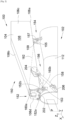
Fig. 2 est une vue en perspective d'un ensemble propulsif selon l'invention, et -
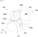
Fig. 3 est un agrandissement de l'attache moteur avant de laFig. 2 . - La
Fig. 1 montre un aéronef 50 qui présente une voilure 52 sous laquelle est monté un ensemble propulsif 100 qui comporte un turboréacteur 102 et un mât d'accrochage 104. - Par convention, on appelle X la direction longitudinale du turboréacteur 102, cette direction X étant parallèle à un axe longitudinal de ce turboréacteur 102. D'autre part, on appelle Y la direction transversale du turboréacteur 102 qui est horizontale lorsque l'aéronef est au sol, et Z la direction verticale ou hauteur verticale lorsque l'aéronef est au sol, ces trois directions X, Y et Z étant orthogonales entre elles.
- D'autre part, les termes " avant " et " arrière " sont à considérer par rapport à une direction d'avancement de l'aéronef lors du fonctionnement du turboréacteur 102, cette direction étant représentée schématiquement par la flèche 107.
- La
Fig. 2 montre l'ensemble propulsif 100 qui comporte le turboréacteur 102 et le mât d'accrochage 104 par lequel le turboréacteur 102 est fixé à la voilure 52. Le mât d'accrochage 104 est ici représenté par sa structure rigide 106, également appelée structure primaire, portant des premiers éléments de fixation 150 destinés à l'accrochage du turboréacteur 102. La structure rigide 106 s'étend selon la direction longitudinale X entre une extrémité avant et une extrémité arrière entre lesquelles se trouve une zone médiane. - Dans le mode de réalisation de l'invention présenté sur la
Fig. 2 , la structure rigide 106 prend la forme d'un caisson qui comporte une paroi inférieure 106a, une paroi supérieure 106b, deux parois latérales 106c et une paroi frontale 106d. - Ces premiers éléments de fixation sont formés d'une attache moteur avant 152, d'une attache moteur arrière 154, ainsi que d'un dispositif de reprise 156 pour reprendre les efforts de poussée générés par le turboréacteur 102.
- Le mât d'accrochage 104 comporte en outre des seconds éléments de fixation permettant la fixation du mât d'accrochage 104, et plus particulièrement de la structure rigide 106, à la voilure 52. Les seconds éléments de fixation ne sont pas représentés sur les Figs., car elles sont hors du périmètre de l'invention et peuvent prendre toutes formes connues par l'homme du métier.
- Le turboréacteur 102 comporte à l'avant un carter de soufflante entourant un canal annulaire de soufflante (également non représenté ici), et à l'intérieur et vers l'arrière du carter de soufflante, un carter central 112 de plus petite dimension, renfermant le coeur du turboréacteur 102 autour d'un axe longitudinal.
- L'attache moteur avant 152 est interposée directement entre une extrémité avant de la structure rigide 106, ici la paroi frontale 106d, et une partie supérieure et avant du carter central 112 par l'intermédiaire d'une ferrure avant 153 solidaire de ladite partie supérieure et avant du carter central 112, ladite partie supérieure étant au niveau d'un plan médian vertical XZ du turboréacteur 102 qui passe par l'axe longitudinal du turboréacteur 102 et qui est par la suite appelé plan médian P.
- Le mât d'accrochage 104 est globalement symétrique par rapport au plan médian P.
- L'attache moteur arrière 154 est interposée directement entre la zone médiane de la structure rigide 106, ici la paroi inférieure 106a, et une ferrure arrière 155 solidaire d'une partie supérieure arrière du carter central 112.
- Le dispositif de reprise 156 comprend deux bielles centrales 158 disposées de part et d'autre du plan médian P et articulées, d'une part, à l'avant, sur une partie avant du carter central 112, et, d'autre part, à l'arrière sur la structure rigide 106 entre l'extrémité avant et la zone médiane.
- L'attache moteur avant 152 comporte de part et d'autre du plan médian P, une bielle avant 152a-b et chaque bielle avant 152a-b est fixée de manière articulée par une de ses extrémités à l'extrémité avant de la structure rigide 106, ici la paroi frontale 106d, et est fixée de manière articulée par l'autre de ses extrémités à la ferrure avant 153.
- Dans le mode de réalisation de l'invention, chaque bielle avant 152a-b est une bielle à deux points de fixation et est fixée par un seul point de liaison à la structure rigide 106 et par un seul point de liaison à la ferrure avant 153.
- Dans le mode de réalisation de l'invention présenté ici, pour chaque bielle avant 152a-b, chaque point de liaison à la structure rigide 106 et à la ferrure avant 153 est constitué par une chape femelle réalisée, respectivement dans la bielle avant 152a-b et dans la ferrure avant 153, par une chape mâle réalisée respectivement par la structure rigide 106 et la bielle avant 152a-b et par un axe de cisaillement, par exemple simple, qui traverse la chape femelle et s'emmanche dans la chape mâle à travers une liaison rotule.
- Du fait de la présence d'un seul point de liaison à l'extrémité de chaque bielle avant 152a-b, chaque bielle avant 152a-b permet une reprise d'un effort le long de ladite bielle avant 152a-b et cet effort comporte des composantes en Y et Z dans un plan frontal perpendiculaire à la direction longitudinale X et contenant les quatre points de liaison des bielles avant 152a-b. La ferrure avant 153 et les bielles avant 152a-b définissent un chemin primaire d'efforts.
- Un tel arrangement évite également l'apparition d'un moment Mx au niveau du plan frontal ce qui permet d'avoir des éléments plus légers et moins chers.
- La direction de l'effort le long de la bielle avant 152a est représentée par la ligne 160a et la direction de l'effort le long de la bielle avant 152b est représentée par la ligne 160b et ces deux droites sont dans le plan frontal et concourantes au niveau d'un point d'intersection.
- Pour des raisons de sécurité, l'attache moteur avant 152 comporte un point de liaison supplémentaire 202 disposé de manière centrale sur le plan médian P et assure une liaison supplémentaire entre la structure rigide 106 et à la ferrure avant 153. Le point de liaison supplémentaire 202 prend la forme d'un point de fixation de sécurité en attente (dit « waiting fail-safe » en langue anglo-saxonne) qui compense une défaillance du chemin primaire d'efforts, c'est-à-dire d'au moins une des bielles avant 152a-b.
- Le point de fixation de sécurité en attente 202 est constitué par exemple d'une chape femelle réalisée dans la ferrure avant 153, d'une chape mâle réalisée par la paroi frontale 106d de la structure rigide 106 et d'un axe emmanché dans ladite chape femelle et qui traverse la chape mâle à travers un alésage prévu à cet effet et dont le diamètre est supérieur au diamètre de l'axe. Ainsi, en fonctionnement normal, il n'y a aucun contact entre l'axe et la paroi frontale 106d de la structure rigide 106, et en cas de rupture de l'une des bielles avant 152a-b, le carter central 112 se déplacerait et l'axe vient alors en contact avec la paroi frontale 106d de la structure rigide 106.
- L'attache moteur arrière 154 comporte une bielle arrière 157 fixée de manière articulée à la ferrure arrière 155 et à une ferrure supérieure 159 solidaire de la structure rigide 106, ici de la paroi inférieure 106a.
- Dans le mode de réalisation de l'invention, la bielle arrière 157 est une bielle à trois points de fixation et est fixée par un point de liaison à la ferrure supérieure 159 et par deux points de liaison à la ferrure arrière 155.
- Dans le mode de réalisation de l'invention présenté ici, chaque point de liaison de la bielle arrière 157 à la ferrure supérieure 159 et à la ferrure arrière 155 est constitué par une chape femelle réalisée dans les ferrures 155 et 159, par une chape mâle constituée de la bielle arrière 157 et par un axe de cisaillement, par exemple simple, qui traverse la chape femelle et s'emmanche dans la chape mâle dans un alésage de la bielle arrière 157 prévu à cet effet à travers une liaison rotule. Pour le point de fixation de sécurité en attente 202, l'axe de cisaillement est préférentiellement un axe double.
- La bielle arrière 157 permet une reprise des efforts en Z et en Y dans un plan arrière perpendiculaire à la direction longitudinale X et contenant les trois points de liaison de la bielle arrière 157.
- La ligne 162 passant respectivement par le point d'intersection des deux axes 160a-b des bielles avant 152a-b et le centre du point de liaison de la bielle arrière 157 à la ferrure supérieure 159 est une ligne dite de torsion (dite « swing line » en anglais).
- Le dispositif de reprise 156 comporte pour chaque bielle centrale 158, une première ferrure 204 solidaire de la structure rigide 106 et une deuxième ferrure 206 solidaire du carter central 112.
- Les deux premières ferrures 204 sont indépendantes l'une de l'autre et chaque première ferrure 204 est fixée sur un des côtés de la structure rigide 106 à une des parois latérales 106c.
- Chaque bielle centrale 158 est fixée de manière articulée par une de ses extrémités à la première ferrure 204 et par l'autre de ses extrémités à la deuxième ferrure 206.
Claims (2)
- Ensemble propulsif (100) d'un aéronef (50), ledit ensemble propulsif (100) comportant:- un turboréacteur (102) comportant un carter central (112) autour d'un axe longitudinal et présentant un plan médian (P) vertical passant par l'axe longitudinal,- un mât d'accrochage (104) présentant une structure rigide (106) qui prend la forme d'un caisson qui comporte une paroi inférieure (106a), une paroi supérieure (106b), deux parois latérales (106c) et une paroi frontale (106d),- une attache moteur avant (152),- une attache moteur arrière (154) interposée entre une zone médiane de la structure rigide (106) et une partie supérieure arrière du carter central (112), et- un dispositif (156) de reprise des efforts de poussée générés par le turboréacteur (102),où l'attache moteur avant (152) comporte de part et d'autre du plan médian (P), une bielle avant (152a-b) et chaque bielle avant (152a-b) est fixée de manière articulée par un point de liaison à une extrémité avant de la structure rigide (106) et par un point de liaison à une ferrure avant (153) solidaire d'une partie supérieure du carter central (112), etoù le dispositif (156) de reprise des efforts de poussée du turboréacteur comporte deux bielles centrales (158) disposées de part et d'autre du plan médian (P), pour chaque bielle centrale (158), une première ferrure (204) solidaire de la structure rigide (106) et une deuxième ferrure (206) solidaire d'une partie avant du carter central (112), où les deux premières ferrures (204) sont indépendantes l'une de l'autre, où chaque bielle centrale (158) est fixée de manière articulée par une de ses extrémités à la première ferrure (204) et par l'autre de ses extrémités à la deuxième ferrure (206) et où l'attache moteur arrière (154) comporte une bielle arrière (157) fixée de manière articulée par deux points de liaison à une ferrure arrière (155) solidaire du carter central (112) et par un point de liaison à une ferrure supérieure (159) solidaire de la structure rigide (106),l'ensemble propulsif (100) étant caractérisé en ce que chaque première ferrure (204) est fixée à une des parois latérales (106c) de la structure rigide (106).
- Aéronef (100) comportant une voilure (52) et un ensemble propulsif (100) selon la revendication précédente dont la structure rigide (106) est fixée sous la voilure (52).
Applications Claiming Priority (1)
| Application Number | Priority Date | Filing Date | Title |
|---|---|---|---|
| FR2108191A FR3125798A1 (fr) | 2021-07-28 | 2021-07-28 | Ensemble propulsif pour aéronef comportant un turboréacteur, un mât et des moyens d’accrochage du turboréacteur au mât |
Publications (2)
| Publication Number | Publication Date |
|---|---|
| EP4124575A1 EP4124575A1 (fr) | 2023-02-01 |
| EP4124575B1 true EP4124575B1 (fr) | 2024-07-17 |
Family
ID=77519382
Family Applications (1)
| Application Number | Title | Priority Date | Filing Date |
|---|---|---|---|
| EP22186620.5A Active EP4124575B1 (fr) | 2021-07-28 | 2022-07-25 | Ensemble propulsif pour aéronef comportant un turboréacteur, un mât et des moyens d accrochage du turboréacteur au mât |
Country Status (4)
| Country | Link |
|---|---|
| US (1) | US20230030853A1 (fr) |
| EP (1) | EP4124575B1 (fr) |
| CN (1) | CN115675887A (fr) |
| FR (1) | FR3125798A1 (fr) |
Families Citing this family (2)
| Publication number | Priority date | Publication date | Assignee | Title |
|---|---|---|---|---|
| FR3086924B1 (fr) * | 2018-10-08 | 2021-02-12 | Safran Aircraft Engines | Turbomachine comportant des moyens de suspension |
| FR3147251A1 (fr) * | 2023-03-30 | 2024-10-04 | Airbus Operations | Ensemble propulsif pour aéronef comportant un turboréacteur, un mât et des moyens d’accrochage du turboréacteur au mât |
Family Cites Families (3)
| Publication number | Priority date | Publication date | Assignee | Title |
|---|---|---|---|---|
| FR2891804B1 (fr) * | 2005-10-12 | 2009-05-01 | Airbus France Sas | Systeme d'ecrou et mat d'accrochage de moteur d'aeronef comprenant un tel systeme |
| FR2963320B1 (fr) * | 2010-07-29 | 2012-09-14 | Airbus Operations Sas | Attache moteur avant amelioree pour moteur d'aeronef |
| US9217337B2 (en) * | 2012-05-10 | 2015-12-22 | United Technologies Corporation | Adjustable engine mount |
-
2021
- 2021-07-28 FR FR2108191A patent/FR3125798A1/fr not_active Ceased
-
2022
- 2022-07-19 US US17/868,161 patent/US20230030853A1/en not_active Abandoned
- 2022-07-25 EP EP22186620.5A patent/EP4124575B1/fr active Active
- 2022-07-27 CN CN202210891408.7A patent/CN115675887A/zh active Pending
Also Published As
| Publication number | Publication date |
|---|---|
| CN115675887A (zh) | 2023-02-03 |
| US20230030853A1 (en) | 2023-02-02 |
| EP4124575A1 (fr) | 2023-02-01 |
| FR3125798A1 (fr) | 2023-02-03 |
Similar Documents
| Publication | Publication Date | Title |
|---|---|---|
| EP1136355B1 (fr) | Dispositif de reprise de poussée apte à relier un turbomoteur et un mât d'aéronef | |
| EP3483069B1 (fr) | Systeme d'attache moteur d'aeronef | |
| EP2167384B1 (fr) | Mât d'accrochage de moteur pour aéronef disposant d'une poutre d'attache moteur arrière formant palonnier | |
| FR3032180A1 (fr) | Ensemble propulsif comportant un turboreacteur et un mat d'accrochage permettant une nouvelle distribution des efforts entre le turboreacteur et la voilure | |
| EP1493663A1 (fr) | Suspension arrière de moteur d'avion avec bielles de reprise de poussée et palonnier en forme de boomerang | |
| EP4124575B1 (fr) | Ensemble propulsif pour aéronef comportant un turboréacteur, un mât et des moyens d accrochage du turboréacteur au mât | |
| EP1773660B1 (fr) | Ensemble moteur pour aeronef | |
| FR3073205A1 (fr) | Attache moteur d'un moteur d'aeronef | |
| EP4484297B1 (fr) | Système d'attache moteur avant pour un moteur d'aéronef qui comporte une structure compacte | |
| EP3486174B1 (fr) | Attache moteur arriere pour un moteur d'aeronef | |
| FR3126695A1 (fr) | Système d’attache moteur avant pour un moteur d’aéronef qui comporte une structure compacte | |
| FR3156756A1 (fr) | Ensemble propulsif pour aéronef comportant un moteur, un mât et des moyens d’accrochage du moteur au mât | |
| FR3096348A1 (fr) | Systeme d’attache moteur avant pour un moteur d’aeronef comportant des systemes de bielles a deux bielles | |
| EP4484298B1 (fr) | Système d attache moteur avant pour un moteur d aéronef qui comporte une structure compacte | |
| EP4438486B1 (fr) | Ensemble propulsif pour aéronef comportant un turboréacteur, un mât et des moyens d'accrochage du turboréacteur au mât | |
| EP4491518B1 (fr) | Ensemble propulseur d'aéronef comprenant une bielle principale d'attache moteur, ainsi que deux bielles de sécurité en parallèle, reliées à un renfort transversal avant d'une structure primaire d'un mât | |
| FR3131734A1 (fr) | Ensemble propulsif pour aéronef comportant un turboréacteur, un mât et des moyens d’accrochage du turboréacteur au mât | |
| FR2887522A1 (fr) | Ensemble pour aeronef comprenant un element de voilure ainsi qu'un mat d'accrochage | |
| FR3096351A1 (fr) | Systeme d’attache moteur arriere pour un moteur d’aeronef comportant une poutre realisee en trois parties | |
| FR3150506A1 (fr) | Système d’attache moteur avant pour un moteur d’aéronef qui comporte une structure compacte | |
| EP4488178B1 (fr) | Assemblage d'un mât d'accrochage avec un moteur d'aéronef | |
| EP4442577B1 (fr) | Mât réacteur pour fixer un moteur d'aéronef | |
| FR3118944A1 (fr) | Structure primaire d’un mât pour la fixation d’un moteur d’aéronef. | |
| EP4342799B1 (fr) | Ensemble de motorisation d'aéronef comportant un dispositif de reprise d'efforts de poussée | |
| EP4438485B1 (fr) | Système central de fixation pour aéronef assurant la fixation d'une structure d'une aile à une structure d'un mât |
Legal Events
| Date | Code | Title | Description |
|---|---|---|---|
| PUAI | Public reference made under article 153(3) epc to a published international application that has entered the european phase |
Free format text: ORIGINAL CODE: 0009012 |
|
| STAA | Information on the status of an ep patent application or granted ep patent |
Free format text: STATUS: THE APPLICATION HAS BEEN PUBLISHED |
|
| AK | Designated contracting states |
Kind code of ref document: A1 Designated state(s): AL AT BE BG CH CY CZ DE DK EE ES FI FR GB GR HR HU IE IS IT LI LT LU LV MC MK MT NL NO PL PT RO RS SE SI SK SM TR |
|
| STAA | Information on the status of an ep patent application or granted ep patent |
Free format text: STATUS: REQUEST FOR EXAMINATION WAS MADE |
|
| 17P | Request for examination filed |
Effective date: 20230719 |
|
| RBV | Designated contracting states (corrected) |
Designated state(s): AL AT BE BG CH CY CZ DE DK EE ES FI FR GB GR HR HU IE IS IT LI LT LU LV MC MK MT NL NO PL PT RO RS SE SI SK SM TR |
|
| GRAP | Despatch of communication of intention to grant a patent |
Free format text: ORIGINAL CODE: EPIDOSNIGR1 |
|
| STAA | Information on the status of an ep patent application or granted ep patent |
Free format text: STATUS: GRANT OF PATENT IS INTENDED |
|
| INTG | Intention to grant announced |
Effective date: 20231220 |
|
| GRAJ | Information related to disapproval of communication of intention to grant by the applicant or resumption of examination proceedings by the epo deleted |
Free format text: ORIGINAL CODE: EPIDOSDIGR1 |
|
| REG | Reference to a national code |
Ref country code: DE Ref legal event code: R079 Free format text: PREVIOUS MAIN CLASS: B64D0027260000 Ipc: B64D0027400000 Ref document number: 602022004579 Country of ref document: DE |
|
| STAA | Information on the status of an ep patent application or granted ep patent |
Free format text: STATUS: REQUEST FOR EXAMINATION WAS MADE |
|
| GRAP | Despatch of communication of intention to grant a patent |
Free format text: ORIGINAL CODE: EPIDOSNIGR1 |
|
| STAA | Information on the status of an ep patent application or granted ep patent |
Free format text: STATUS: GRANT OF PATENT IS INTENDED |
|
| INTC | Intention to grant announced (deleted) | ||
| RIC1 | Information provided on ipc code assigned before grant |
Ipc: B64D 27/40 20240101AFI20240129BHEP |
|
| INTG | Intention to grant announced |
Effective date: 20240214 |
|
| GRAS | Grant fee paid |
Free format text: ORIGINAL CODE: EPIDOSNIGR3 |
|
| GRAA | (expected) grant |
Free format text: ORIGINAL CODE: 0009210 |
|
| STAA | Information on the status of an ep patent application or granted ep patent |
Free format text: STATUS: THE PATENT HAS BEEN GRANTED |
|
| AK | Designated contracting states |
Kind code of ref document: B1 Designated state(s): AL AT BE BG CH CY CZ DE DK EE ES FI FR GB GR HR HU IE IS IT LI LT LU LV MC MK MT NL NO PL PT RO RS SE SI SK SM TR |
|
| REG | Reference to a national code |
Ref country code: CH Ref legal event code: EP |
|
| REG | Reference to a national code |
Ref country code: DE Ref legal event code: R096 Ref document number: 602022004579 Country of ref document: DE |
|
| REG | Reference to a national code |
Ref country code: IE Ref legal event code: FG4D Free format text: LANGUAGE OF EP DOCUMENT: FRENCH |
|
| REG | Reference to a national code |
Ref country code: LT Ref legal event code: MG9D |
|
| REG | Reference to a national code |
Ref country code: NL Ref legal event code: MP Effective date: 20240717 |
|
| PG25 | Lapsed in a contracting state [announced via postgrant information from national office to epo] |
Ref country code: PT Free format text: LAPSE BECAUSE OF FAILURE TO SUBMIT A TRANSLATION OF THE DESCRIPTION OR TO PAY THE FEE WITHIN THE PRESCRIBED TIME-LIMIT Effective date: 20241118 |
|
| REG | Reference to a national code |
Ref country code: AT Ref legal event code: MK05 Ref document number: 1703898 Country of ref document: AT Kind code of ref document: T Effective date: 20240717 |
|
| PG25 | Lapsed in a contracting state [announced via postgrant information from national office to epo] |
Ref country code: NL Free format text: LAPSE BECAUSE OF FAILURE TO SUBMIT A TRANSLATION OF THE DESCRIPTION OR TO PAY THE FEE WITHIN THE PRESCRIBED TIME-LIMIT Effective date: 20240717 |
|
| PG25 | Lapsed in a contracting state [announced via postgrant information from national office to epo] |
Ref country code: PT Free format text: LAPSE BECAUSE OF FAILURE TO SUBMIT A TRANSLATION OF THE DESCRIPTION OR TO PAY THE FEE WITHIN THE PRESCRIBED TIME-LIMIT Effective date: 20241118 Ref country code: NL Free format text: LAPSE BECAUSE OF FAILURE TO SUBMIT A TRANSLATION OF THE DESCRIPTION OR TO PAY THE FEE WITHIN THE PRESCRIBED TIME-LIMIT Effective date: 20240717 |
|
| PG25 | Lapsed in a contracting state [announced via postgrant information from national office to epo] |
Ref country code: NO Free format text: LAPSE BECAUSE OF FAILURE TO SUBMIT A TRANSLATION OF THE DESCRIPTION OR TO PAY THE FEE WITHIN THE PRESCRIBED TIME-LIMIT Effective date: 20241017 |
|
| PG25 | Lapsed in a contracting state [announced via postgrant information from national office to epo] |
Ref country code: GR Free format text: LAPSE BECAUSE OF FAILURE TO SUBMIT A TRANSLATION OF THE DESCRIPTION OR TO PAY THE FEE WITHIN THE PRESCRIBED TIME-LIMIT Effective date: 20241018 Ref country code: FI Free format text: LAPSE BECAUSE OF FAILURE TO SUBMIT A TRANSLATION OF THE DESCRIPTION OR TO PAY THE FEE WITHIN THE PRESCRIBED TIME-LIMIT Effective date: 20240717 Ref country code: PL Free format text: LAPSE BECAUSE OF FAILURE TO SUBMIT A TRANSLATION OF THE DESCRIPTION OR TO PAY THE FEE WITHIN THE PRESCRIBED TIME-LIMIT Effective date: 20240717 |
|
| PG25 | Lapsed in a contracting state [announced via postgrant information from national office to epo] |
Ref country code: BG Free format text: LAPSE BECAUSE OF FAILURE TO SUBMIT A TRANSLATION OF THE DESCRIPTION OR TO PAY THE FEE WITHIN THE PRESCRIBED TIME-LIMIT Effective date: 20240717 |
|
| PG25 | Lapsed in a contracting state [announced via postgrant information from national office to epo] |
Ref country code: LV Free format text: LAPSE BECAUSE OF FAILURE TO SUBMIT A TRANSLATION OF THE DESCRIPTION OR TO PAY THE FEE WITHIN THE PRESCRIBED TIME-LIMIT Effective date: 20240717 |
|
| PG25 | Lapsed in a contracting state [announced via postgrant information from national office to epo] |
Ref country code: AT Free format text: LAPSE BECAUSE OF FAILURE TO SUBMIT A TRANSLATION OF THE DESCRIPTION OR TO PAY THE FEE WITHIN THE PRESCRIBED TIME-LIMIT Effective date: 20240717 Ref country code: IS Free format text: LAPSE BECAUSE OF FAILURE TO SUBMIT A TRANSLATION OF THE DESCRIPTION OR TO PAY THE FEE WITHIN THE PRESCRIBED TIME-LIMIT Effective date: 20241117 |
|
| PG25 | Lapsed in a contracting state [announced via postgrant information from national office to epo] |
Ref country code: HR Free format text: LAPSE BECAUSE OF FAILURE TO SUBMIT A TRANSLATION OF THE DESCRIPTION OR TO PAY THE FEE WITHIN THE PRESCRIBED TIME-LIMIT Effective date: 20240717 |
|
| PG25 | Lapsed in a contracting state [announced via postgrant information from national office to epo] |
Ref country code: ES Free format text: LAPSE BECAUSE OF FAILURE TO SUBMIT A TRANSLATION OF THE DESCRIPTION OR TO PAY THE FEE WITHIN THE PRESCRIBED TIME-LIMIT Effective date: 20240717 Ref country code: RS Free format text: LAPSE BECAUSE OF FAILURE TO SUBMIT A TRANSLATION OF THE DESCRIPTION OR TO PAY THE FEE WITHIN THE PRESCRIBED TIME-LIMIT Effective date: 20241017 |
|
| PG25 | Lapsed in a contracting state [announced via postgrant information from national office to epo] |
Ref country code: RS Free format text: LAPSE BECAUSE OF FAILURE TO SUBMIT A TRANSLATION OF THE DESCRIPTION OR TO PAY THE FEE WITHIN THE PRESCRIBED TIME-LIMIT Effective date: 20241017 Ref country code: PL Free format text: LAPSE BECAUSE OF FAILURE TO SUBMIT A TRANSLATION OF THE DESCRIPTION OR TO PAY THE FEE WITHIN THE PRESCRIBED TIME-LIMIT Effective date: 20240717 Ref country code: NO Free format text: LAPSE BECAUSE OF FAILURE TO SUBMIT A TRANSLATION OF THE DESCRIPTION OR TO PAY THE FEE WITHIN THE PRESCRIBED TIME-LIMIT Effective date: 20241017 Ref country code: LV Free format text: LAPSE BECAUSE OF FAILURE TO SUBMIT A TRANSLATION OF THE DESCRIPTION OR TO PAY THE FEE WITHIN THE PRESCRIBED TIME-LIMIT Effective date: 20240717 Ref country code: IS Free format text: LAPSE BECAUSE OF FAILURE TO SUBMIT A TRANSLATION OF THE DESCRIPTION OR TO PAY THE FEE WITHIN THE PRESCRIBED TIME-LIMIT Effective date: 20241117 Ref country code: HR Free format text: LAPSE BECAUSE OF FAILURE TO SUBMIT A TRANSLATION OF THE DESCRIPTION OR TO PAY THE FEE WITHIN THE PRESCRIBED TIME-LIMIT Effective date: 20240717 Ref country code: GR Free format text: LAPSE BECAUSE OF FAILURE TO SUBMIT A TRANSLATION OF THE DESCRIPTION OR TO PAY THE FEE WITHIN THE PRESCRIBED TIME-LIMIT Effective date: 20241018 Ref country code: FI Free format text: LAPSE BECAUSE OF FAILURE TO SUBMIT A TRANSLATION OF THE DESCRIPTION OR TO PAY THE FEE WITHIN THE PRESCRIBED TIME-LIMIT Effective date: 20240717 Ref country code: ES Free format text: LAPSE BECAUSE OF FAILURE TO SUBMIT A TRANSLATION OF THE DESCRIPTION OR TO PAY THE FEE WITHIN THE PRESCRIBED TIME-LIMIT Effective date: 20240717 Ref country code: BG Free format text: LAPSE BECAUSE OF FAILURE TO SUBMIT A TRANSLATION OF THE DESCRIPTION OR TO PAY THE FEE WITHIN THE PRESCRIBED TIME-LIMIT Effective date: 20240717 Ref country code: AT Free format text: LAPSE BECAUSE OF FAILURE TO SUBMIT A TRANSLATION OF THE DESCRIPTION OR TO PAY THE FEE WITHIN THE PRESCRIBED TIME-LIMIT Effective date: 20240717 |
|
| PG25 | Lapsed in a contracting state [announced via postgrant information from national office to epo] |
Ref country code: LU Free format text: LAPSE BECAUSE OF NON-PAYMENT OF DUE FEES Effective date: 20240725 |
|
| PG25 | Lapsed in a contracting state [announced via postgrant information from national office to epo] |
Ref country code: LU Free format text: LAPSE BECAUSE OF NON-PAYMENT OF DUE FEES Effective date: 20240725 |
|
| PG25 | Lapsed in a contracting state [announced via postgrant information from national office to epo] |
Ref country code: DK Free format text: LAPSE BECAUSE OF FAILURE TO SUBMIT A TRANSLATION OF THE DESCRIPTION OR TO PAY THE FEE WITHIN THE PRESCRIBED TIME-LIMIT Effective date: 20240717 Ref country code: SM Free format text: LAPSE BECAUSE OF FAILURE TO SUBMIT A TRANSLATION OF THE DESCRIPTION OR TO PAY THE FEE WITHIN THE PRESCRIBED TIME-LIMIT Effective date: 20240717 Ref country code: RO Free format text: LAPSE BECAUSE OF FAILURE TO SUBMIT A TRANSLATION OF THE DESCRIPTION OR TO PAY THE FEE WITHIN THE PRESCRIBED TIME-LIMIT Effective date: 20240717 |
|
| REG | Reference to a national code |
Ref country code: DE Ref legal event code: R097 Ref document number: 602022004579 Country of ref document: DE |
|
| PG25 | Lapsed in a contracting state [announced via postgrant information from national office to epo] |
Ref country code: BE Free format text: LAPSE BECAUSE OF NON-PAYMENT OF DUE FEES Effective date: 20240731 Ref country code: EE Free format text: LAPSE BECAUSE OF FAILURE TO SUBMIT A TRANSLATION OF THE DESCRIPTION OR TO PAY THE FEE WITHIN THE PRESCRIBED TIME-LIMIT Effective date: 20240717 Ref country code: MC Free format text: LAPSE BECAUSE OF FAILURE TO SUBMIT A TRANSLATION OF THE DESCRIPTION OR TO PAY THE FEE WITHIN THE PRESCRIBED TIME-LIMIT Effective date: 20240717 |
|
| PG25 | Lapsed in a contracting state [announced via postgrant information from national office to epo] |
Ref country code: CZ Free format text: LAPSE BECAUSE OF FAILURE TO SUBMIT A TRANSLATION OF THE DESCRIPTION OR TO PAY THE FEE WITHIN THE PRESCRIBED TIME-LIMIT Effective date: 20240717 |
|
| PG25 | Lapsed in a contracting state [announced via postgrant information from national office to epo] |
Ref country code: SK Free format text: LAPSE BECAUSE OF FAILURE TO SUBMIT A TRANSLATION OF THE DESCRIPTION OR TO PAY THE FEE WITHIN THE PRESCRIBED TIME-LIMIT Effective date: 20240717 |
|
| PLBE | No opposition filed within time limit |
Free format text: ORIGINAL CODE: 0009261 |
|
| STAA | Information on the status of an ep patent application or granted ep patent |
Free format text: STATUS: NO OPPOSITION FILED WITHIN TIME LIMIT |
|
| REG | Reference to a national code |
Ref country code: BE Ref legal event code: MM Effective date: 20240731 |
|
| 26N | No opposition filed |
Effective date: 20250422 |
|
| PG25 | Lapsed in a contracting state [announced via postgrant information from national office to epo] |
Ref country code: IE Free format text: LAPSE BECAUSE OF NON-PAYMENT OF DUE FEES Effective date: 20240725 |
|
| PG25 | Lapsed in a contracting state [announced via postgrant information from national office to epo] |
Ref country code: SE Free format text: LAPSE BECAUSE OF FAILURE TO SUBMIT A TRANSLATION OF THE DESCRIPTION OR TO PAY THE FEE WITHIN THE PRESCRIBED TIME-LIMIT Effective date: 20240717 |
|
| PGFP | Annual fee paid to national office [announced via postgrant information from national office to epo] |
Ref country code: DE Payment date: 20250722 Year of fee payment: 4 |
|
| PGFP | Annual fee paid to national office [announced via postgrant information from national office to epo] |
Ref country code: FR Payment date: 20250725 Year of fee payment: 4 |
|
| PG25 | Lapsed in a contracting state [announced via postgrant information from national office to epo] |
Ref country code: IT Free format text: LAPSE BECAUSE OF FAILURE TO SUBMIT A TRANSLATION OF THE DESCRIPTION OR TO PAY THE FEE WITHIN THE PRESCRIBED TIME-LIMIT Effective date: 20240717 Ref country code: CY Free format text: LAPSE BECAUSE OF FAILURE TO SUBMIT A TRANSLATION OF THE DESCRIPTION OR TO PAY THE FEE WITHIN THE PRESCRIBED TIME-LIMIT; INVALID AB INITIO Effective date: 20220725 |
|
| REG | Reference to a national code |
Ref country code: CH Ref legal event code: H13 Free format text: ST27 STATUS EVENT CODE: U-0-0-H10-H13 (AS PROVIDED BY THE NATIONAL OFFICE) Effective date: 20260224 |
|
| PG25 | Lapsed in a contracting state [announced via postgrant information from national office to epo] |
Ref country code: HU Free format text: LAPSE BECAUSE OF FAILURE TO SUBMIT A TRANSLATION OF THE DESCRIPTION OR TO PAY THE FEE WITHIN THE PRESCRIBED TIME-LIMIT; INVALID AB INITIO Effective date: 20220725 |
|
| PG25 | Lapsed in a contracting state [announced via postgrant information from national office to epo] |
Ref country code: CH Free format text: LAPSE BECAUSE OF NON-PAYMENT OF DUE FEES Effective date: 20250731 |