EP4124573A1 - Ice protection system and method for an aircraft component, aircraft compo-nent and aircraft using such a system - Google Patents
Ice protection system and method for an aircraft component, aircraft compo-nent and aircraft using such a system Download PDFInfo
- Publication number
- EP4124573A1 EP4124573A1 EP21188523.1A EP21188523A EP4124573A1 EP 4124573 A1 EP4124573 A1 EP 4124573A1 EP 21188523 A EP21188523 A EP 21188523A EP 4124573 A1 EP4124573 A1 EP 4124573A1
- Authority
- EP
- European Patent Office
- Prior art keywords
- aircraft
- phase change
- change material
- temperature
- ice
- Prior art date
- Legal status (The legal status is an assumption and is not a legal conclusion. Google has not performed a legal analysis and makes no representation as to the accuracy of the status listed.)
- Granted
Links
Images

Classifications
-
- B—PERFORMING OPERATIONS; TRANSPORTING
- B64—AIRCRAFT; AVIATION; COSMONAUTICS
- B64D—EQUIPMENT FOR FITTING IN OR TO AIRCRAFT; FLIGHT SUITS; PARACHUTES; ARRANGEMENT OR MOUNTING OF POWER PLANTS OR PROPULSION TRANSMISSIONS IN AIRCRAFT
- B64D15/00—De-icing or preventing icing on exterior surfaces of aircraft
-
- B—PERFORMING OPERATIONS; TRANSPORTING
- B64—AIRCRAFT; AVIATION; COSMONAUTICS
- B64D—EQUIPMENT FOR FITTING IN OR TO AIRCRAFT; FLIGHT SUITS; PARACHUTES; ARRANGEMENT OR MOUNTING OF POWER PLANTS OR PROPULSION TRANSMISSIONS IN AIRCRAFT
- B64D15/00—De-icing or preventing icing on exterior surfaces of aircraft
- B64D15/20—Means for detecting icing or initiating de-icing
-
- C—CHEMISTRY; METALLURGY
- C09—DYES; PAINTS; POLISHES; NATURAL RESINS; ADHESIVES; COMPOSITIONS NOT OTHERWISE PROVIDED FOR; APPLICATIONS OF MATERIALS NOT OTHERWISE PROVIDED FOR
- C09K—MATERIALS FOR MISCELLANEOUS APPLICATIONS, NOT PROVIDED FOR ELSEWHERE
- C09K5/00—Heat-transfer, heat-exchange or heat-storage materials, e.g. refrigerants; Materials for the production of heat or cold by chemical reactions other than by combustion
- C09K5/02—Materials undergoing a change of physical state when used
- C09K5/06—Materials undergoing a change of physical state when used the change of state being from liquid to solid or vice versa
- C09K5/063—Materials absorbing or liberating heat during crystallisation; Heat storage materials
-
- B—PERFORMING OPERATIONS; TRANSPORTING
- B64—AIRCRAFT; AVIATION; COSMONAUTICS
- B64D—EQUIPMENT FOR FITTING IN OR TO AIRCRAFT; FLIGHT SUITS; PARACHUTES; ARRANGEMENT OR MOUNTING OF POWER PLANTS OR PROPULSION TRANSMISSIONS IN AIRCRAFT
- B64D33/00—Arrangement in aircraft of power plant parts or auxiliaries not otherwise provided for
- B64D33/02—Arrangement in aircraft of power plant parts or auxiliaries not otherwise provided for of combustion air intakes
- B64D2033/0233—Arrangement in aircraft of power plant parts or auxiliaries not otherwise provided for of combustion air intakes comprising de-icing means
-
- C—CHEMISTRY; METALLURGY
- C09—DYES; PAINTS; POLISHES; NATURAL RESINS; ADHESIVES; COMPOSITIONS NOT OTHERWISE PROVIDED FOR; APPLICATIONS OF MATERIALS NOT OTHERWISE PROVIDED FOR
- C09K—MATERIALS FOR MISCELLANEOUS APPLICATIONS, NOT PROVIDED FOR ELSEWHERE
- C09K3/00—Materials not provided for elsewhere
- C09K3/18—Materials not provided for elsewhere for application to surfaces to minimize adherence of ice, mist or water thereto; Thawing or antifreeze materials for application to surfaces
Definitions
- the invention relates to an ice protection system configured for an aircraft component of an aircraft.
- the invention further relates to an aircraft component and aircraft using such a system.
- the invention also relates to a method for de-icing or preventing ice accretion and a use of phase change material.
- IPS on-board ice protection systems
- electrical or thermal energy for preventing ice formation on an aircraft or an aircraft component, or for removing accreted ice from said aircraft or component. Ice can also be removed chemically, using hot de-icing fluids sprayed on the aircraft or aircraft component that have the function of melting the ice and lowering the freezing point of water. All these solutions consume large amounts of energy or are environmentally difficult.
- the invention provides an ice protection system configured for an aircraft component of an aircraft, wherein the ice protection system includes a phase change material that is configured for storing thermal energy, when the temperature of the phase change material goes above a first temperature, and for releasing previously stored thermal energy when the temperature goes below a second temperature that is lower than the first temperature.
- the ice protection system further comprises a trigger device that is configured to initiate phase change within the phase change material.
- the trigger device includes an electrically conductive wiring that is operatively coupled to the phase change material.
- the trigger device includes an electromagnet that is arranged adjacent or within the phase change material.
- the trigger device includes a light source that is arranged to irradiate the phase change material.
- the ice protection system further comprises an ice detection system that is configured to detect accretion of ice on the aircraft component and that is operatively coupled to the phase change material, so as to initiate a phase change upon detection of accretion of ice.
- an ice detection system that is configured to detect accretion of ice on the aircraft component and that is operatively coupled to the phase change material, so as to initiate a phase change upon detection of accretion of ice.
- the phase change material is configured to undergo a volume change upon undergoing a phase change, so as to generate interfacial stress for delaminating ice from the aircraft component.
- the ice protection system further comprises a thermally conducting cover layer that is arranged to cover the phase change material and that is configured to thermally conduct the thermal energy to be stored and released by the phase change material from the phase change material to its surface.
- the first temperature is from 5 °C to 40 °C.
- the first temperature is from 5 °C to 30 °C.
- the first temperature is from 10 °C to 40 °C.
- the first temperature is from 10 °C to 30 °C.
- the first temperature is from 20 °C to 30 °C.
- the first temperature is from 24 °C to 26 °C.
- the first temperature is 25 °C.
- the second temperature is from above -10 °C to below +5 °C.
- the second temperature is from above -10 °C to below +2 °C.
- the second temperature is from above -10 °C to below -2 °C.
- the second temperature is from above -5 °C to below +5 °C.
- the second temperature is from above -5 °C to below +2 °C.
- the second temperature is from above -5 °C to below -2°C.
- the second temperature is from above 0 °C to below 5 °C.
- the second temperature is from above 0 °C to below 2 °C.
- the second temperature is below 5 °C.
- the second temperature is below 2 °C.
- the second temperature is below 1 °C.
- the second temperature is below -2 °C.
- the invention provides an aircraft component for an aircraft, the aircraft component comprising an ice protection system according to any of the preceding claims and an exposed surface that is exposed such that ice is able to accrete, wherein the phase change material is arranged on the exposed surface or at least the exposed surface is made of the phase change material.
- the aircraft component mainly up to totally consists of the phase change material.
- the aircraft component is a leading edge portion of a wing of an aircraft, and the exposed surface is arranged on both sides of a stagnation line of the leading edge portion.
- the aircraft component is a rotor blade of an aircraft, and at least one exposed surface is arranged on one blade of the rotor blade.
- the aircraft component is an air intake of an aircraft, and the exposed surface is arranged on an inner circumferential surface and/or leading surface of the air intake.
- the aircraft component is a probe of an aircraft, and the exposed surface is arranged on an outer circumferential surface of the probe.
- the invention provides an aircraft comprising a preferred ice protection system and/or a preferred aircraft component.
- the invention provides a method for de-icing or preventing ice accretion on an exposed surface of an aircraft component by
- the invention proposes using a phase change material for de-icing an exposed surface of an aircraft component of an aircraft.
- the technical field of the invention is ice protection systems and strategies for aircraft of any kind.
- some aircraft may be not allowed to take off and fly, (ii) some aircraft are certified for flight in limited icing conditions, and (iii) some aircraft are certified for flight in all icing conditions.
- the respective aircraft need to have some sort of ice protection strategy or system installed that allows reducing or preventing the risk of icing of aircraft structures like wings, rudder, engine inlets, propellers, air intakes, probes, etc.
- Active systems are currently used that either shed off the ice mechanically or melt the ice by providing sufficient heat to melt the ice. Such systems need electrical power from power packs, heat generated by the engines, or other on-board power systems.
- the solution (Phase Change Materials - PCM) proposed in this disclosure provides heat generated chemically (by a solid-solid or solid-liquid phase change) for ice protection of different aircraft components (like wing leading edges, rotor blades, air intakes, probes, etc.) or aircraft (like small H/C, UAV, drones, or urban air mobility applications).
- the PCM can be applied as a coating to the components or products, or it can be a structural element.
- PCM Phase Change Materials
- PCM Phase Change Materials
- PCM are used as heat source for thermal ice protection of aircraft components. The components could be made out of the PCM or be coated by a PCM-based coating.
- the advantages of using PCM for selected components in selected icing conditions are manifold (it should be noted that not all advantages need to be present at the same time): (i) the technical solution does not require wiring or piping systems for conducting electricity or heat from a remote location on the aircraft; (ii) no energy other than that already stored in the PCM is consumed during operation; (iii) the system can be used unlimited times, because the phase change process is reversible; (iv) maintenance is foreseen to be extremely limited (the system is ideally maintenance-free); (v) no emissions are produced during operation and the operation of the PCM is basically CO 2 neutral due to the reversible phase change process.
- PCM Phase Change Materials
- One embodiment of the PCM solution is to coat the rotor blade of a drone with a PCM-based coating that can release enough heat to protect the rotor blade from light icing conditions.
- PCM solution could be to manufacture (e.g., by 3D printing, extruding, or hot embossing) the rotor blades directly from PCM.
- volume of PCM is larger and so also the amount of stored energy.
- This solution could be used for more severe icing conditions or for ice protection for an extended time.
- the simplest case is to have an available PCM that cycles between ⁇ 1°C and +25 °C.
- the phase change process is triggered and the PCM releases heat.
- This way, it ideally maintains a constant temperature of 1°C during all the phase change process (can be up to 10 minutes, e.g.), or cools down more slowly than the surroundings during the phase change.
- the system is "recharged" when its temperature rises above 25°C and the phase change is reversed.
- the system releases heat only upon trespassing a critical temperature and irrespective of icing conditions or only cold weather conditions occur.
- One idea is to add an electrical trigger that can kick-off the phase change at any desired time or temperature.
- the available PCM can then cycle between T low and +25 °C, so that the phase change preferably does not occur in natural flying conditions that are determined by T low and that are different and adjustable for each different aircraft or mission profile.
- the operator of the aircraft can decide when to turn on the PCM-based ice protection.
- a signal is provided by a connected ice detection system.
- the ideal PCM is able to store/release a huge heat density [in kJ/kg].
- the energy density of the PCM is preferably large enough to be effective for the intended application or for the intended mission.
- Some PCMs show a more or less pronounced volume change when they undergo a phase change. Volume change is associated with a surface area change and thus the generation of an interfacial stress, which may cause delamination of accreted ice upon phase change.
- a larger volume of PCM is installed inside the component and coated with a thin protective and thermally conducting paint to transfer the energy to the ice and protect the component from ice accretion.
- Fig. 1 depicts an embodiment of an aircraft 10.
- the aircraft 10 has a fuselage 12 and a pair of wings 14 attached thereto.
- the aircraft 10 further comprises engines 16 for propulsion.
- the aircraft 10 includes a horizontal tail plane 18 and a vertical tail plane 20.
- the airplane 10 includes control surfaces 22, such as elevator 24, rudder 26, and ailerons 28.
- the aircraft 10 includes high-lift devices 30, such as slats 32 and flaps 34.
- the aforementioned parts are examples of aircraft components 36.
- a rotor 38 is another example of an aircraft component 36. It should be noted that - while the invention is described for the sake of brevity with respect to the aircraft 10 and the rotor 38, the invention is also applicable to other types of aircraft and other aircraft components.
- the rotor 38 has a plurality of rotor blades 40, of which only two are depicted here, and a rotor hub 42.
- the rotor blades 40 have an exposed surface 44 that is arranged such that ice can accrete during operation.
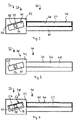
- the rotor blade 40 is schematically shown once as a cross-section and once in a side view.
- the rotor 38 has an ice protection system 46.
- the ice protection system 46 includes a phase change material 48.
- the phase change material 48 is arranged on the exposed surface 44 as an anti-ice coating 50.
- Fig. 3 depicts a variant of the rotor 38 which is made in its entirety from the phase change material 48. It should be noted that in this case the phase change is a solid-solid phase change.
- Fig. 4 depicts a variant of the rotor 38 that has a phase change insert 52 that is integrated into the rotor blades 40.
- the phase change insert 52 is made of or includes the phase change material.
- this rotor 38 also comprises a thermally conducting cover layer 54 that is arranged on the phase change insert 52, so as to protect the phase change insert 52 and allow storing and releasing of thermal energy.
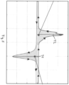
- the phase change material 48 has a first temperature T1 and a second temperature T2. If the temperature of the phase change material 48 exceeds the first temperature T1, the phase change material 48 undergoes a phase change so that thermal energy is stored in the phase change material 48. If the temperature of the phase change material 48 crosses the second temperature T2 from above, then the thermal energy that was previously stored in the phase change material 48 is released.
- the curves for heating (arrows from left to right) and cooling (arrows from right to left) are offset for better visibility.
- the ice protection system 46 may include an ice detection system (not depicted) that determines whether a formation of ice is taking place. In this case, the ice detection system generates a signal indicative of the ice formation. The signal may be processed by a control unit or the operator of the aircraft 10. In any case, the ice protection system 46 may include a trigger device 56.
- the trigger device 56 is configured for enabling the phase change material 48 to undergo phase changes.
- the trigger device 54 may be an electrical wire, an electromagnet or a light source depending on the type of phase change material 48.
- the invention proposes to provide an aircraft component (36) of an aircraft (10) or the aircraft (10) on its exposed surface (44) with a phase change material (48).
- the phase change material (48) stores thermal energy above a first temperature (T1) and releases the previously stored thermal energy below a second temperature (T2).
Landscapes
- Engineering & Computer Science (AREA)
- Chemical & Material Sciences (AREA)
- Aviation & Aerospace Engineering (AREA)
- Physics & Mathematics (AREA)
- Chemical Kinetics & Catalysis (AREA)
- Combustion & Propulsion (AREA)
- Thermal Sciences (AREA)
- Materials Engineering (AREA)
- Organic Chemistry (AREA)
- Control Of Resistance Heating (AREA)
- Materials Applied To Surfaces To Minimize Adherence Of Mist Or Water (AREA)
Abstract
Description
- The invention relates to an ice protection system configured for an aircraft component of an aircraft. The invention further relates to an aircraft component and aircraft using such a system. The invention also relates to a method for de-icing or preventing ice accretion and a use of phase change material.
- Current on-board ice protection systems (IPS) use electrical or thermal energy for preventing ice formation on an aircraft or an aircraft component, or for removing accreted ice from said aircraft or component. Ice can also be removed chemically, using hot de-icing fluids sprayed on the aircraft or aircraft component that have the function of melting the ice and lowering the freezing point of water. All these solutions consume large amounts of energy or are environmentally difficult.
- It is the object of the invention to reduce power consumption for de-icing or ice prevention.
- The object is achieved by the subject-matter of the independent claims. Preferred embodiments are subject-matter of the dependent claims.
- The invention provides an ice protection system configured for an aircraft component of an aircraft, wherein the ice protection system includes a phase change material that is configured for storing thermal energy, when the temperature of the phase change material goes above a first temperature, and for releasing previously stored thermal energy when the temperature goes below a second temperature that is lower than the first temperature.
- Preferably, the ice protection system further comprises a trigger device that is configured to initiate phase change within the phase change material. Preferably, the trigger device includes an electrically conductive wiring that is operatively coupled to the phase change material. Preferably, the trigger device includes an electromagnet that is arranged adjacent or within the phase change material. Preferably, the trigger device includes a light source that is arranged to irradiate the phase change material.
- Preferably, the ice protection system further comprises an ice detection system that is configured to detect accretion of ice on the aircraft component and that is operatively coupled to the phase change material, so as to initiate a phase change upon detection of accretion of ice.
- Preferably, the phase change material is configured to undergo a volume change upon undergoing a phase change, so as to generate interfacial stress for delaminating ice from the aircraft component.
- Preferably, the ice protection system further comprises a thermally conducting cover layer that is arranged to cover the phase change material and that is configured to thermally conduct the thermal energy to be stored and released by the phase change material from the phase change material to its surface.
- Preferably, the first temperature is from 5 °C to 40 °C. Preferably, the first temperature is from 5 °C to 30 °C. Preferably, the first temperature is from 10 °C to 40 °C. Preferably, the first temperature is from 10 °C to 30 °C. Preferably, the first temperature is from 20 °C to 30 °C. Preferably, the first temperature is from 24 °C to 26 °C. Preferably, the first temperature is 25 °C.
- Preferably, the second temperature is from above -10 °C to below +5 °C. Preferably, the second temperature is from above -10 °C to below +2 °C. Preferably, the second temperature is from above -10 °C to below -2 °C. Preferably, the second temperature is from above -5 °C to below +5 °C. Preferably, the second temperature is from above -5 °C to below +2 °C. Preferably, the second temperature is from above -5 °C to below -2°C. Preferably, the second temperature is from above 0 °C to below 5 °C. Preferably, the second temperature is from above 0 °C to below 2 °C. Preferably, the second temperature is below 5 °C. Preferably, the second temperature is below 2 °C. Preferably, the second temperature is below 1 °C. Preferably, the second temperature is below -2 °C.
- The invention provides an aircraft component for an aircraft, the aircraft component comprising an ice protection system according to any of the preceding claims and an exposed surface that is exposed such that ice is able to accrete, wherein the phase change material is arranged on the exposed surface or at least the exposed surface is made of the phase change material.
- Preferably, the aircraft component mainly up to totally consists of the phase change material.
- Preferably, the aircraft component is a leading edge portion of a wing of an aircraft, and the exposed surface is arranged on both sides of a stagnation line of the leading edge portion.
- Preferably, the aircraft component is a rotor blade of an aircraft, and at least one exposed surface is arranged on one blade of the rotor blade.
- Preferably, the aircraft component is an air intake of an aircraft, and the exposed surface is arranged on an inner circumferential surface and/or leading surface of the air intake.
- Preferably, the aircraft component is a probe of an aircraft, and the exposed surface is arranged on an outer circumferential surface of the probe.
- The invention provides an aircraft comprising a preferred ice protection system and/or a preferred aircraft component.
- The invention provides a method for de-icing or preventing ice accretion on an exposed surface of an aircraft component by
- coating the exposed surface with or manufacturing the exposed surface or aircraft component out of a phase change material that is configured for storing thermal energy, when the temperature of the phase change material goes above a first temperature, and for releasing previously stored thermal energy when the temperature goes below a second temperature that is lower than the first temperature; and
- triggering a phase change in the phase change material by exposing the phase change material to different temperatures and/or by activating a trigger device configured for initiating a phase change in the phase change material.
- The invention proposes using a phase change material for de-icing an exposed surface of an aircraft component of an aircraft.
- The technical field of the invention is ice protection systems and strategies for aircraft of any kind. In inclement weather and specifically icing conditions, (i) some aircraft may be not allowed to take off and fly, (ii) some aircraft are certified for flight in limited icing conditions, and (iii) some aircraft are certified for flight in all icing conditions. In cases (ii) and (iii) the respective aircraft need to have some sort of ice protection strategy or system installed that allows reducing or preventing the risk of icing of aircraft structures like wings, rudder, engine inlets, propellers, air intakes, probes, etc. Active systems are currently used that either shed off the ice mechanically or melt the ice by providing sufficient heat to melt the ice. Such systems need electrical power from power packs, heat generated by the engines, or other on-board power systems.
- The solution (Phase Change Materials - PCM) proposed in this disclosure provides heat generated chemically (by a solid-solid or solid-liquid phase change) for ice protection of different aircraft components (like wing leading edges, rotor blades, air intakes, probes, etc.) or aircraft (like small H/C, UAV, drones, or urban air mobility applications).
- The PCM can be applied as a coating to the components or products, or it can be a structural element.
- Phase Change Materials (PCM) allow a low-power and environmentally friendly solution for some icing conditions. PCM have been investigated as convenient energy storage solutions in aerospace. They allow storing energy at a given temperature - mainly as heat - and releasing this energy again - mainly as heat - at another temperature. The released heat can be used as it is or for powering energy converters and producing electricity. In the frame of the current invention, PCM are used as heat source for thermal ice protection of aircraft components. The components could be made out of the PCM or be coated by a PCM-based coating. The advantages of using PCM for selected components in selected icing conditions are manifold (it should be noted that not all advantages need to be present at the same time): (i) the technical solution does not require wiring or piping systems for conducting electricity or heat from a remote location on the aircraft; (ii) no energy other than that already stored in the PCM is consumed during operation; (iii) the system can be used unlimited times, because the phase change process is reversible; (iv) maintenance is foreseen to be extremely limited (the system is ideally maintenance-free); (v) no emissions are produced during operation and the operation of the PCM is basically CO2 neutral due to the reversible phase change process.
- The invention is about using a class of materials known as Phase Change Materials (PCM) as replacement or in support of current ice protection systems for aircraft components. PCM are able to store energy in chemical form, i.e. as enthalpy of phase transition, at a defined first temperature T1 and release it at a second temperature T2. For the purpose described here, T1 > T2, e.g. T1 = 20 °C and T2 = 0 °C. When the ambient temperature T > T1, the PCM undergoes a phase transition and stores thermal energy from the surroundings. When T < T2, the PCM undergoes another phase transition and releases the stored thermal energy to the surroundings.
- This is explained herein with the example of the PCM system Zn(NO3)2·6H2O + Mn(NO3)2·4H2O. It should be noted that there are numerous PCM known that are suitable for the disclosed application, but which are not explicitly listed herein.
- One embodiment of the PCM solution is to coat the rotor blade of a drone with a PCM-based coating that can release enough heat to protect the rotor blade from light icing conditions.
- Another embodiment of the PCM solution could be to manufacture (e.g., by 3D printing, extruding, or hot embossing) the rotor blades directly from PCM. In this case, the volume of PCM is larger and so also the amount of stored energy. This solution could be used for more severe icing conditions or for ice protection for an extended time.
- The simplest case is to have an available PCM that cycles between ∼1°C and +25 °C. When the temperature of the PCM decreases below 1°C, the phase change process is triggered and the PCM releases heat. This way, it ideally maintains a constant temperature of 1°C during all the phase change process (can be up to 10 minutes, e.g.), or cools down more slowly than the surroundings during the phase change. The system is "recharged" when its temperature rises above 25°C and the phase change is reversed.
- This way, however, the system releases heat only upon trespassing a critical temperature and irrespective of icing conditions or only cold weather conditions occur. One idea is to add an electrical trigger that can kick-off the phase change at any desired time or temperature. The available PCM can then cycle between Tlow and +25 °C, so that the phase change preferably does not occur in natural flying conditions that are determined by Tlow and that are different and adjustable for each different aircraft or mission profile. The operator of the aircraft can decide when to turn on the PCM-based ice protection. In another variant a signal is provided by a connected ice detection system.
- The ideal PCM is able to store/release a huge heat density [in kJ/kg]. The energy density of the PCM is preferably large enough to be effective for the intended application or for the intended mission.
- Some PCMs show a more or less pronounced volume change when they undergo a phase change. Volume change is associated with a surface area change and thus the generation of an interfacial stress, which may cause delamination of accreted ice upon phase change.
- In order to improve the energy that is stored in the PCM and ensure sufficient ice protection due to larger amount of heat, preferably, a larger volume of PCM is installed inside the component and coated with a thin protective and thermally conducting paint to transfer the energy to the ice and protect the component from ice accretion.
- Embodiments of the invention are described in more detail with reference to the accompanying schematic drawings that are listed below
- Fig. 1
- depicts an embodiment of an aircraft;
- Fig. 2
- depicts an embodiment of an aircraft component;
- Fig. 3
- depicts another embodiment of an aircraft component;
- Fig. 4
- depicts yet another embodiment of an aircraft component;
- Fig. 5
- depicts a differential scanning calorimetry (DSC) diagram illustrating the phase changes.
-
Fig. 1 depicts an embodiment of anaircraft 10. Theaircraft 10 has afuselage 12 and a pair ofwings 14 attached thereto. Theaircraft 10 further comprisesengines 16 for propulsion. Theaircraft 10 includes a horizontal tail plane 18 and a vertical tail plane 20. Furthermore, theairplane 10 includes control surfaces 22, such as elevator 24,rudder 26, andailerons 28. Furthermore, theaircraft 10 includes high-lift devices 30, such as slats 32 and flaps 34. The aforementioned parts are examples ofaircraft components 36. - Referring to
Fig. 2 , arotor 38 is another example of anaircraft component 36. It should be noted that - while the invention is described for the sake of brevity with respect to theaircraft 10 and therotor 38, the invention is also applicable to other types of aircraft and other aircraft components. - The
rotor 38 has a plurality ofrotor blades 40, of which only two are depicted here, and arotor hub 42. Therotor blades 40 have an exposedsurface 44 that is arranged such that ice can accrete during operation. Therotor blade 40 is schematically shown once as a cross-section and once in a side view. Therotor 38 has anice protection system 46. Theice protection system 46 includes aphase change material 48. Thephase change material 48 is arranged on the exposedsurface 44 as ananti-ice coating 50. -
Fig. 3 depicts a variant of therotor 38 which is made in its entirety from thephase change material 48. It should be noted that in this case the phase change is a solid-solid phase change. -
Fig. 4 depicts a variant of therotor 38 that has aphase change insert 52 that is integrated into therotor blades 40. Thephase change insert 52 is made of or includes the phase change material. In addition, thisrotor 38 also comprises a thermally conducting cover layer 54 that is arranged on thephase change insert 52, so as to protect thephase change insert 52 and allow storing and releasing of thermal energy. - As illustrated in
Fig. 5 , thephase change material 48 has a first temperature T1 and a second temperature T2. If the temperature of thephase change material 48 exceeds the first temperature T1, thephase change material 48 undergoes a phase change so that thermal energy is stored in thephase change material 48. If the temperature of thephase change material 48 crosses the second temperature T2 from above, then the thermal energy that was previously stored in thephase change material 48 is released. The curves for heating (arrows from left to right) and cooling (arrows from right to left) are offset for better visibility. - Independent of the embodiment, the
ice protection system 46 may include an ice detection system (not depicted) that determines whether a formation of ice is taking place. In this case, the ice detection system generates a signal indicative of the ice formation. The signal may be processed by a control unit or the operator of theaircraft 10. In any case, theice protection system 46 may include atrigger device 56. Thetrigger device 56 is configured for enabling thephase change material 48 to undergo phase changes. The trigger device 54 may be an electrical wire, an electromagnet or a light source depending on the type ofphase change material 48. - In order to reduce power consumption for de-icing or ice prevention, the invention proposes to provide an aircraft component (36) of an aircraft (10) or the aircraft (10) on its exposed surface (44) with a phase change material (48). The phase change material (48) stores thermal energy above a first temperature (T1) and releases the previously stored thermal energy below a second temperature (T2).
-
- 10
- aircraft
- 12
- fuselage
- 14
- wing
- 16
- engine
- 18
- horizontal tail plane
- 20
- vertical tail plane
- 22
- control surface
- 24
- elevator
- 26
- rudder
- 28
- ailerons
- 30
- high-lift device
- 32
- slat
- 34
- flap
- 36
- aircraft component
- 38
- rotor
- 40
- rotor blades
- 42
- rotor hub
- 44
- exposed surface
- 46
- ice protection system
- 48
- phase change material
- 50
- anti-ice coating
- 52
- phase change insert
- 54
- thermally conducting cover layer
- 56
- trigger device
- T1
- first temperature
- T2
- second temperature
Claims (15)
- An ice protection system (46) configured for an aircraft component (36) of an aircraft (10) or for an aircraft (10), wherein the ice protection system (46) includes a phase change material (48) that is configured for storing thermal energy, when the temperature of the phase change material (48) goes above a first temperature (T1), and for releasing previously stored thermal energy when the temperature goes below a second temperature (T2) that is lower than the first temperature (T1).
- The ice protection system (46) according claim 1, further comprising a trigger device (56) that is configured to enable phase change within the phase change material (48).
- The ice protection system (46) according to any of the preceding claims, further comprising an ice detection system that is configured to detect accretion of ice on the aircraft component (36) or aircraft (10) and that is operatively coupled to the phase change material (48), so as to initiate a phase change upon detection of accretion of ice.
- The ice protection system (46) according to any of the preceding claims, wherein the phase change material (48) is configured to undergo a volume change upon undergoing a phase change, so as to generate interfacial stress for delaminating ice from the aircraft component (36) or aircraft (10).
- The ice protection system (46) according to any of the preceding claims, further comprising a thermally conducting cover layer (54) that is arranged to cover the phase change material (48) and that is configured to thermally conduct the thermal energy to be stored and released by the phase change material (48) from the phase change material (48) to its surface and back.
- The ice protection system (46) according to any of the preceding claims, wherein the first temperature (T1) is from 5 °C to 40 °C.
- The ice protection system (46) according to any of the preceding claims, wherein the second temperature (T2) is from above -10 °C to below +5 °C.
- An aircraft component (36) for an aircraft (10), the aircraft component (36) comprising an ice protection system (46) according to any of the preceding claims and an exposed surface (44) that is exposed such that ice is able to accrete, wherein the phase change material (48) is arranged on the exposed surface (44) or at least the exposed surface (44) is made of the phase change material (48).
- The aircraft component (36) according to claim 8, wherein the aircraft component (36) is a leading edge portion of a wing (14) of an aircraft (10), and the exposed surface (44) is arranged on both sides of a stagnation line of the leading edge portion, or is a wing (14) and the exposed surface is arranged on the upper and/or lower wing surface.
- The aircraft component (36) according to claim 8, wherein the aircraft component is a rotor (38) of an aircraft, and at least one exposed surface (44) is arranged on one rotor blade (40).
- The aircraft component (36) according to claim 8, wherein the aircraft component (36) is an air intake of an aircraft (10), and the exposed surface (44) is arranged on an inner circumferential surface and/or leading surface of the air intake.
- The aircraft component (36) according to claim 8, wherein the aircraft component (36) is a probe of an aircraft (10), and the exposed surface is arranged on an outer circumferential surface of the probe.
- An aircraft (10) comprising an ice protection system (46) according to any of the claims 1 to 7 and/or an aircraft component (36) according to any of the claims 8 to 12.
- A method for de-icing or preventing ice accretion on an exposed surface (44) of an aircraft component (36) or of an aircraft (10) by- coating the exposed surface (44) with or manufacturing the exposed surface (44) or aircraft component (36) out of a phase change material (48) that is configured for storing thermal energy, when the temperature of the phase change material (48) goes above a first temperature (T1), and for releasing previously stored thermal energy when the temperature goes below a second temperature (T2) that is lower than the first temperature (T1); and- triggering a phase change in the phase change material (48) by exposing the phase change material (48) to different temperatures and/or by activating a trigger device (56) configured for initiating a phase change in the phase change material (48).
- Using a phase change material (48) for de-icing an exposed surface (44) of an aircraft component (36) of an aircraft (10) or an aircraft (10).
Priority Applications (1)
| Application Number | Priority Date | Filing Date | Title |
|---|---|---|---|
| EP21188523.1A EP4124573B1 (en) | 2021-07-29 | 2021-07-29 | Ice protection system and method for an aircraft component, aircraft compo-nent and aircraft using such a system |
Applications Claiming Priority (1)
| Application Number | Priority Date | Filing Date | Title |
|---|---|---|---|
| EP21188523.1A EP4124573B1 (en) | 2021-07-29 | 2021-07-29 | Ice protection system and method for an aircraft component, aircraft compo-nent and aircraft using such a system |
Publications (2)
| Publication Number | Publication Date |
|---|---|
| EP4124573A1 true EP4124573A1 (en) | 2023-02-01 |
| EP4124573B1 EP4124573B1 (en) | 2025-06-18 |
Family
ID=77126684
Family Applications (1)
| Application Number | Title | Priority Date | Filing Date |
|---|---|---|---|
| EP21188523.1A Active EP4124573B1 (en) | 2021-07-29 | 2021-07-29 | Ice protection system and method for an aircraft component, aircraft compo-nent and aircraft using such a system |
Country Status (1)
| Country | Link |
|---|---|
| EP (1) | EP4124573B1 (en) |
Citations (5)
| Publication number | Priority date | Publication date | Assignee | Title |
|---|---|---|---|---|
| WO1995034189A1 (en) * | 1994-06-06 | 1995-12-14 | Innovative Dynamics, Inc. | Shape memory alloy de-icing technology |
| CN110963044A (en) * | 2019-12-24 | 2020-04-07 | 南京航空航天大学 | Wing anti-icing device based on nanocomposite phase change material and its working method |
| WO2020180826A1 (en) * | 2019-03-01 | 2020-09-10 | The Board Of Trustees Of The University Of Illinois | Compositions and methods for inhibiting ice formation on surfaces |
| EP3750810A1 (en) * | 2019-06-14 | 2020-12-16 | Rosemount Aerospace Inc. | Friction energy savers |
| CN113086163A (en) * | 2021-04-09 | 2021-07-09 | 南京航空航天大学 | Anti-icing and deicing device, wing, aircraft and wing anti-icing and deicing method |
-
2021
- 2021-07-29 EP EP21188523.1A patent/EP4124573B1/en active Active
Patent Citations (5)
| Publication number | Priority date | Publication date | Assignee | Title |
|---|---|---|---|---|
| WO1995034189A1 (en) * | 1994-06-06 | 1995-12-14 | Innovative Dynamics, Inc. | Shape memory alloy de-icing technology |
| WO2020180826A1 (en) * | 2019-03-01 | 2020-09-10 | The Board Of Trustees Of The University Of Illinois | Compositions and methods for inhibiting ice formation on surfaces |
| EP3750810A1 (en) * | 2019-06-14 | 2020-12-16 | Rosemount Aerospace Inc. | Friction energy savers |
| CN110963044A (en) * | 2019-12-24 | 2020-04-07 | 南京航空航天大学 | Wing anti-icing device based on nanocomposite phase change material and its working method |
| CN113086163A (en) * | 2021-04-09 | 2021-07-09 | 南京航空航天大学 | Anti-icing and deicing device, wing, aircraft and wing anti-icing and deicing method |
Also Published As
| Publication number | Publication date |
|---|---|
| EP4124573B1 (en) | 2025-06-18 |
Similar Documents
| Publication | Publication Date | Title |
|---|---|---|
| US7546980B2 (en) | Aircraft wing with electrothermal deicing and/or anti-icing device | |
| US6330986B1 (en) | Aircraft de-icing system | |
| US6237874B1 (en) | Zoned aircraft de-icing system and method | |
| De Pauw et al. | Effect of superhydrophobic coating on the anti-icing and deicing of an airfoil | |
| Shinkafi et al. | Enhanced method of conceptual sizing of aircraft electro-thermal de-icing system | |
| US7124983B2 (en) | Hybrid electrical ice protection system and method including an energy saving mode | |
| US10822097B2 (en) | Ice formation detection and removal system for an aerial vehicle and method | |
| US5615849A (en) | Microwave deicing and anti-icing system for aircraft | |
| CN112572808B (en) | Double-layer anti-icing and electric heating structure and wing adopting same | |
| EP2795119B1 (en) | De-icing of a wind turbine blade | |
| Al-Khalil et al. | A hybrid anti-icing ice protection system | |
| US12187442B2 (en) | System for providing protection from icing using a fuel cell | |
| CN116280213A (en) | Wing thermal coupling deicing device and method | |
| EP4124573B1 (en) | Ice protection system and method for an aircraft component, aircraft compo-nent and aircraft using such a system | |
| Müller et al. | UAV icing: Validation of an ice protection system design for a propeller | |
| Gerardi et al. | A shape memory alloy based de-icing system for aircraft | |
| US20260042541A1 (en) | Systems and Methods for an Ice Runback Control Zone in an Electrothermal Ice Protection System | |
| CN114435597A (en) | Temperature difference power generation device for wing anti-icing and deicing assembly, anti-icing and deicing assembly and method | |
| CA2375544C (en) | Aircraft de-icing system | |
| Fu et al. | Introduction and state of the art of anti/de-icing technologies | |
| EP1873060A1 (en) | Hybrid electrical ice protection system and method including an energy saving mode | |
| CN114852344B (en) | A new anti-icing system based on active and passive coupling | |
| COFFMAN, JR | Review of helicopter icing protection systems | |
| RU2677741C1 (en) | Aircraft | |
| Zheng | Influence of Magnetism on the Icing Processes of water Droplets on cold surfaces |
Legal Events
| Date | Code | Title | Description |
|---|---|---|---|
| PUAI | Public reference made under article 153(3) epc to a published international application that has entered the european phase |
Free format text: ORIGINAL CODE: 0009012 |
|
| STAA | Information on the status of an ep patent application or granted ep patent |
Free format text: STATUS: THE APPLICATION HAS BEEN PUBLISHED |
|
| AK | Designated contracting states |
Kind code of ref document: A1 Designated state(s): AL AT BE BG CH CY CZ DE DK EE ES FI FR GB GR HR HU IE IS IT LI LT LU LV MC MK MT NL NO PL PT RO RS SE SI SK SM TR |
|
| STAA | Information on the status of an ep patent application or granted ep patent |
Free format text: STATUS: REQUEST FOR EXAMINATION WAS MADE |
|
| 17P | Request for examination filed |
Effective date: 20230728 |
|
| RBV | Designated contracting states (corrected) |
Designated state(s): AL AT BE BG CH CY CZ DE DK EE ES FI FR GB GR HR HU IE IS IT LI LT LU LV MC MK MT NL NO PL PT RO RS SE SI SK SM TR |
|
| GRAP | Despatch of communication of intention to grant a patent |
Free format text: ORIGINAL CODE: EPIDOSNIGR1 |
|
| STAA | Information on the status of an ep patent application or granted ep patent |
Free format text: STATUS: GRANT OF PATENT IS INTENDED |
|
| GRAJ | Information related to disapproval of communication of intention to grant by the applicant or resumption of examination proceedings by the epo deleted |
Free format text: ORIGINAL CODE: EPIDOSDIGR1 |
|
| STAA | Information on the status of an ep patent application or granted ep patent |
Free format text: STATUS: REQUEST FOR EXAMINATION WAS MADE |
|
| GRAP | Despatch of communication of intention to grant a patent |
Free format text: ORIGINAL CODE: EPIDOSNIGR1 |
|
| STAA | Information on the status of an ep patent application or granted ep patent |
Free format text: STATUS: GRANT OF PATENT IS INTENDED |
|
| RIC1 | Information provided on ipc code assigned before grant |
Ipc: B64D 33/02 20060101ALN20241007BHEP Ipc: C09K 3/18 20060101ALI20241007BHEP Ipc: C09K 5/06 20060101ALI20241007BHEP Ipc: F28D 20/02 20060101ALI20241007BHEP Ipc: B64D 15/20 20060101ALI20241007BHEP Ipc: B64D 15/00 20060101AFI20241007BHEP |
|
| INTG | Intention to grant announced |
Effective date: 20241017 |
|
| INTG | Intention to grant announced |
Effective date: 20241024 |
|
| RIC1 | Information provided on ipc code assigned before grant |
Ipc: B64D 33/02 20060101ALN20241021BHEP Ipc: C09K 3/18 20060101ALI20241021BHEP Ipc: C09K 5/06 20060101ALI20241021BHEP Ipc: F28D 20/02 20060101ALI20241021BHEP Ipc: B64D 15/20 20060101ALI20241021BHEP Ipc: B64D 15/00 20060101AFI20241021BHEP |
|
| RIN1 | Information on inventor provided before grant (corrected) |
Inventor name: DIAZ BARJA, MIGUEL Inventor name: BLAZQUEZ MUNOZ, PABLO Inventor name: HUET, FLORENT Inventor name: DEZITTER, FABIEN Inventor name: CARUHEL, CAMILLE Inventor name: VERCILLO, VITTORIO Inventor name: BONACCURSO, ELMAR |
|
| GRAS | Grant fee paid |
Free format text: ORIGINAL CODE: EPIDOSNIGR3 |
|
| GRAA | (expected) grant |
Free format text: ORIGINAL CODE: 0009210 |
|
| STAA | Information on the status of an ep patent application or granted ep patent |
Free format text: STATUS: THE PATENT HAS BEEN GRANTED |
|
| AK | Designated contracting states |
Kind code of ref document: B1 Designated state(s): AL AT BE BG CH CY CZ DE DK EE ES FI FR GB GR HR HU IE IS IT LI LT LU LV MC MK MT NL NO PL PT RO RS SE SI SK SM TR |
|
| REG | Reference to a national code |
Ref country code: GB Ref legal event code: FG4D |
|
| REG | Reference to a national code |
Ref country code: CH Ref legal event code: EP |
|
| REG | Reference to a national code |
Ref country code: DE Ref legal event code: R096 Ref document number: 602021032351 Country of ref document: DE |
|
| REG | Reference to a national code |
Ref country code: CH Ref legal event code: EP |
|
| REG | Reference to a national code |
Ref country code: IE Ref legal event code: FG4D |
|
| PG25 | Lapsed in a contracting state [announced via postgrant information from national office to epo] |
Ref country code: FI Free format text: LAPSE BECAUSE OF FAILURE TO SUBMIT A TRANSLATION OF THE DESCRIPTION OR TO PAY THE FEE WITHIN THE PRESCRIBED TIME-LIMIT Effective date: 20250618 |
|
| PGFP | Annual fee paid to national office [announced via postgrant information from national office to epo] |
Ref country code: DE Payment date: 20250722 Year of fee payment: 5 |
|
| REG | Reference to a national code |
Ref country code: LT Ref legal event code: MG9D |
|
| PG25 | Lapsed in a contracting state [announced via postgrant information from national office to epo] |
Ref country code: GR Free format text: LAPSE BECAUSE OF FAILURE TO SUBMIT A TRANSLATION OF THE DESCRIPTION OR TO PAY THE FEE WITHIN THE PRESCRIBED TIME-LIMIT Effective date: 20250919 Ref country code: NO Free format text: LAPSE BECAUSE OF FAILURE TO SUBMIT A TRANSLATION OF THE DESCRIPTION OR TO PAY THE FEE WITHIN THE PRESCRIBED TIME-LIMIT Effective date: 20250918 |
|
| PG25 | Lapsed in a contracting state [announced via postgrant information from national office to epo] |
Ref country code: BG Free format text: LAPSE BECAUSE OF FAILURE TO SUBMIT A TRANSLATION OF THE DESCRIPTION OR TO PAY THE FEE WITHIN THE PRESCRIBED TIME-LIMIT Effective date: 20250618 |
|
| PGFP | Annual fee paid to national office [announced via postgrant information from national office to epo] |
Ref country code: GB Payment date: 20250724 Year of fee payment: 5 |
|
| PG25 | Lapsed in a contracting state [announced via postgrant information from national office to epo] |
Ref country code: HR Free format text: LAPSE BECAUSE OF FAILURE TO SUBMIT A TRANSLATION OF THE DESCRIPTION OR TO PAY THE FEE WITHIN THE PRESCRIBED TIME-LIMIT Effective date: 20250618 |
|
| PGFP | Annual fee paid to national office [announced via postgrant information from national office to epo] |
Ref country code: FR Payment date: 20250812 Year of fee payment: 5 Ref country code: AT Payment date: 20251020 Year of fee payment: 5 |
|
| PG25 | Lapsed in a contracting state [announced via postgrant information from national office to epo] |
Ref country code: RS Free format text: LAPSE BECAUSE OF FAILURE TO SUBMIT A TRANSLATION OF THE DESCRIPTION OR TO PAY THE FEE WITHIN THE PRESCRIBED TIME-LIMIT Effective date: 20250918 |
|
| REG | Reference to a national code |
Ref country code: NL Ref legal event code: MP Effective date: 20250618 |
|
| PG25 | Lapsed in a contracting state [announced via postgrant information from national office to epo] |
Ref country code: LV Free format text: LAPSE BECAUSE OF FAILURE TO SUBMIT A TRANSLATION OF THE DESCRIPTION OR TO PAY THE FEE WITHIN THE PRESCRIBED TIME-LIMIT Effective date: 20250618 |
|
| PG25 | Lapsed in a contracting state [announced via postgrant information from national office to epo] |
Ref country code: NL Free format text: LAPSE BECAUSE OF FAILURE TO SUBMIT A TRANSLATION OF THE DESCRIPTION OR TO PAY THE FEE WITHIN THE PRESCRIBED TIME-LIMIT Effective date: 20250618 |
|
| PG25 | Lapsed in a contracting state [announced via postgrant information from national office to epo] |
Ref country code: PT Free format text: LAPSE BECAUSE OF FAILURE TO SUBMIT A TRANSLATION OF THE DESCRIPTION OR TO PAY THE FEE WITHIN THE PRESCRIBED TIME-LIMIT Effective date: 20251020 |
|
| REG | Reference to a national code |
Ref country code: AT Ref legal event code: MK05 Ref document number: 1803995 Country of ref document: AT Kind code of ref document: T Effective date: 20250618 |
|
| PG25 | Lapsed in a contracting state [announced via postgrant information from national office to epo] |
Ref country code: IS Free format text: LAPSE BECAUSE OF FAILURE TO SUBMIT A TRANSLATION OF THE DESCRIPTION OR TO PAY THE FEE WITHIN THE PRESCRIBED TIME-LIMIT Effective date: 20251018 |
|
| PG25 | Lapsed in a contracting state [announced via postgrant information from national office to epo] |
Ref country code: AT Free format text: LAPSE BECAUSE OF FAILURE TO SUBMIT A TRANSLATION OF THE DESCRIPTION OR TO PAY THE FEE WITHIN THE PRESCRIBED TIME-LIMIT Effective date: 20250618 Ref country code: SM Free format text: LAPSE BECAUSE OF FAILURE TO SUBMIT A TRANSLATION OF THE DESCRIPTION OR TO PAY THE FEE WITHIN THE PRESCRIBED TIME-LIMIT Effective date: 20250618 |
|
| PG25 | Lapsed in a contracting state [announced via postgrant information from national office to epo] |
Ref country code: CZ Free format text: LAPSE BECAUSE OF FAILURE TO SUBMIT A TRANSLATION OF THE DESCRIPTION OR TO PAY THE FEE WITHIN THE PRESCRIBED TIME-LIMIT Effective date: 20250618 |
|
| PG25 | Lapsed in a contracting state [announced via postgrant information from national office to epo] |
Ref country code: PL Free format text: LAPSE BECAUSE OF FAILURE TO SUBMIT A TRANSLATION OF THE DESCRIPTION OR TO PAY THE FEE WITHIN THE PRESCRIBED TIME-LIMIT Effective date: 20250618 |
|
| PG25 | Lapsed in a contracting state [announced via postgrant information from national office to epo] |
Ref country code: EE Free format text: LAPSE BECAUSE OF FAILURE TO SUBMIT A TRANSLATION OF THE DESCRIPTION OR TO PAY THE FEE WITHIN THE PRESCRIBED TIME-LIMIT Effective date: 20250618 |
|
| PG25 | Lapsed in a contracting state [announced via postgrant information from national office to epo] |
Ref country code: SK Free format text: LAPSE BECAUSE OF FAILURE TO SUBMIT A TRANSLATION OF THE DESCRIPTION OR TO PAY THE FEE WITHIN THE PRESCRIBED TIME-LIMIT Effective date: 20250618 |
|
| PG25 | Lapsed in a contracting state [announced via postgrant information from national office to epo] |
Ref country code: ES Free format text: LAPSE BECAUSE OF FAILURE TO SUBMIT A TRANSLATION OF THE DESCRIPTION OR TO PAY THE FEE WITHIN THE PRESCRIBED TIME-LIMIT Effective date: 20250618 |
|
| REG | Reference to a national code |
Ref country code: CH Ref legal event code: H13 Free format text: ST27 STATUS EVENT CODE: U-0-0-H10-H13 (AS PROVIDED BY THE NATIONAL OFFICE) Effective date: 20260224 |
|
| PG25 | Lapsed in a contracting state [announced via postgrant information from national office to epo] |
Ref country code: RO Free format text: LAPSE BECAUSE OF FAILURE TO SUBMIT A TRANSLATION OF THE DESCRIPTION OR TO PAY THE FEE WITHIN THE PRESCRIBED TIME-LIMIT Effective date: 20250618 Ref country code: LU Free format text: LAPSE BECAUSE OF NON-PAYMENT OF DUE FEES Effective date: 20250729 |
|
| REG | Reference to a national code |
Ref country code: DE Ref legal event code: R097 Ref document number: 602021032351 Country of ref document: DE |
|
| REG | Reference to a national code |
Ref country code: BE Ref legal event code: MM Effective date: 20250731 |
|
| PG25 | Lapsed in a contracting state [announced via postgrant information from national office to epo] |
Ref country code: MC Free format text: LAPSE BECAUSE OF FAILURE TO SUBMIT A TRANSLATION OF THE DESCRIPTION OR TO PAY THE FEE WITHIN THE PRESCRIBED TIME-LIMIT Effective date: 20250618 |
|
| PG25 | Lapsed in a contracting state [announced via postgrant information from national office to epo] |
Ref country code: DK Free format text: LAPSE BECAUSE OF FAILURE TO SUBMIT A TRANSLATION OF THE DESCRIPTION OR TO PAY THE FEE WITHIN THE PRESCRIBED TIME-LIMIT Effective date: 20250618 |
|
| PG25 | Lapsed in a contracting state [announced via postgrant information from national office to epo] |
Ref country code: IT Free format text: LAPSE BECAUSE OF FAILURE TO SUBMIT A TRANSLATION OF THE DESCRIPTION OR TO PAY THE FEE WITHIN THE PRESCRIBED TIME-LIMIT Effective date: 20250618 Ref country code: BE Free format text: LAPSE BECAUSE OF NON-PAYMENT OF DUE FEES Effective date: 20250731 |
|
| PG25 | Lapsed in a contracting state [announced via postgrant information from national office to epo] |
Ref country code: CH Free format text: LAPSE BECAUSE OF NON-PAYMENT OF DUE FEES Effective date: 20250731 |
|
| PLBE | No opposition filed within time limit |
Free format text: ORIGINAL CODE: 0009261 |
|
| STAA | Information on the status of an ep patent application or granted ep patent |
Free format text: STATUS: NO OPPOSITION FILED WITHIN TIME LIMIT |
|
| REG | Reference to a national code |
Ref country code: CH Ref legal event code: L10 Free format text: ST27 STATUS EVENT CODE: U-0-0-L10-L00 (AS PROVIDED BY THE NATIONAL OFFICE) Effective date: 20260430 |