EP4124485A1 - Dimmable transparent roof assembly - Google Patents
Dimmable transparent roof assembly Download PDFInfo
- Publication number
- EP4124485A1 EP4124485A1 EP21188651.0A EP21188651A EP4124485A1 EP 4124485 A1 EP4124485 A1 EP 4124485A1 EP 21188651 A EP21188651 A EP 21188651A EP 4124485 A1 EP4124485 A1 EP 4124485A1
- Authority
- EP
- European Patent Office
- Prior art keywords
- electrode layer
- signal electrode
- dimmable
- roof assembly
- common electrode
- Prior art date
- Legal status (The legal status is an assumption and is not a legal conclusion. Google has not performed a legal analysis and makes no representation as to the accuracy of the status listed.)
- Withdrawn
Links
- 229910000679 solder Inorganic materials 0.000 description 3
- 230000004913 activation Effects 0.000 description 2
- RYGMFSIKBFXOCR-UHFFFAOYSA-N Copper Chemical compound [Cu] RYGMFSIKBFXOCR-UHFFFAOYSA-N 0.000 description 1
- 229910052802 copper Inorganic materials 0.000 description 1
- 239000010949 copper Substances 0.000 description 1
Images

Classifications
-
- G—PHYSICS
- G02—OPTICS
- G02F—OPTICAL DEVICES OR ARRANGEMENTS FOR THE CONTROL OF LIGHT BY MODIFICATION OF THE OPTICAL PROPERTIES OF THE MEDIA OF THE ELEMENTS INVOLVED THEREIN; NON-LINEAR OPTICS; FREQUENCY-CHANGING OF LIGHT; OPTICAL LOGIC ELEMENTS; OPTICAL ANALOGUE/DIGITAL CONVERTERS
- G02F1/00—Devices or arrangements for the control of the intensity, colour, phase, polarisation or direction of light arriving from an independent light source, e.g. switching, gating or modulating; Non-linear optics
- G02F1/01—Devices or arrangements for the control of the intensity, colour, phase, polarisation or direction of light arriving from an independent light source, e.g. switching, gating or modulating; Non-linear optics for the control of the intensity, phase, polarisation or colour
- G02F1/15—Devices or arrangements for the control of the intensity, colour, phase, polarisation or direction of light arriving from an independent light source, e.g. switching, gating or modulating; Non-linear optics for the control of the intensity, phase, polarisation or colour based on an electrochromic effect
- G02F1/153—Constructional details
- G02F1/155—Electrodes
-
- B—PERFORMING OPERATIONS; TRANSPORTING
- B60—VEHICLES IN GENERAL
- B60J—WINDOWS, WINDSCREENS, NON-FIXED ROOFS, DOORS, OR SIMILAR DEVICES FOR VEHICLES; REMOVABLE EXTERNAL PROTECTIVE COVERINGS SPECIALLY ADAPTED FOR VEHICLES
- B60J3/00—Antiglare equipment associated with windows or windscreens; Sun visors for vehicles
- B60J3/04—Antiglare equipment associated with windows or windscreens; Sun visors for vehicles adjustable in transparency
Definitions
- the invention relates to a dimmable transparent roof assembly intended for use in the roof of a vehicle, comprising a central electrically dimmable layer, a common electrode layer on one surface of the dimmable layer which is connected to a common electrode line, a signal electrode layer on the opposite surface of the dimmable layer and two support layers on the surfaces of the common electrode layer and of the signal electrode layer, respectively, facing away from the dimmable layer, wherein the signal electrode layer, as seen in a longitudinal direction of the roof assembly, is divided into signal electrode layer sections each extending in a transverse direction between opposite section ends.
- the signal electrode layer sections are grouped into two different groups, wherein all signal electrode layer sections of one group at corresponding ones of the section ends are connected to respective signal electrode lines, whereas all signal electrode layer sections of the other group at corresponding opposite ones of the section ends are connected to respective signal electrode lines and wherein the signal electrode lines extend longitudinally along side edges of the roof assembly which correspond with the respective section ends.
- the signal electrode lines no longer all extend at the same side edge, but are divided over the two side edges, thus limiting the overall width of the signal electrode lines extending at the same side edge, which allows to increase the daylight opening size of the roof assembly. Or, put in another manner, this allows an increase of the number of signal electrode layer sections without arriving at an unacceptable overall width of the signal electrode lines.
- the difference between the number of signal electrode layer sections in the two different groups is at most 1.
- the number of signal electrode layer sections in the two different groups will be identical when there are an even number of sections, thus evenly dividing the signal electrode lines over both side edges of the roof assembly.
- the two different groups may be defined in many different manners. As non-limiting examples the following embodiments are mentioned: the signal electrode layer sections belonging to the same group are arranged adjacent each other, wherein the two different groups are positioned adjacent to each other as viewed in the longitudinal direction; the signal electrode layer sections belonging to one group are divided into two different subgroups each comprising signal electrode layer sections arranged adjacent each other, whereas the signal electrode layer sections belonging to the other group are arranged adjacent each other into a single group which, as viewed in the longitudinal direction, is positioned between the two subgroups; the signal electrode layer sections are arranged such that, as viewed in the longitudinal direction, signal electrode layer sections belonging to one group and signal electrode layer sections belonging to the other group alternate.
- the central electrically dimmable layer, the common electrode layer and the support layer on the common electrode layer are inwardly recessed at the section ends where signal electrode lines are connected to the signal electrode layer sections.
- the signal electrode layer is locally exposed and is accessible for a connection to a respective signal electrode line, for example by applying solder or a conductive paste between the signal electrode layer and the signal electrode line. Further, such a recess results in sufficient space for accommodating the signal electrode lines (and possibly a common electrode line) extending longitudinally along the respective side edge of the roof assembly.
- the common electrode line is connected to the common electrode layer at an edge location of the roof assembly where no signal electrode line connects to a section end. This allows to minimize the thickness of the roof assembly.
- the common electrode layer which is common for at least a number of signal electrode layer sections, may be carried out in different ways. For example, it is conceivable that there is only one common electrode layer for all signal electrode layer sections. Thus, the roof assembly then has only one common electrode layer, which also needs only one common electrode line.
- the connection of such a single common electrode line to the single common electrode layer can occur at any of a number of different edge locations, but preferably, then, the common electrode line is connected to the common electrode layer at a forward or rearward edge of the roof assembly.
- a separate common electrode layer for each group with its respective common electrode line.
- a common electrode line of a group is connected to a corresponding common electrode layer at a side edge of the roof assembly opposite the section ends to which the signal electrode lines of said group are connected, wherein said common electrode line extends longitudinally along said side edge. This allows a very convenient and optimized positioning of the common electrode lines with respect to the signal electrode lines.
- the central electrically dimmable layer, the signal electrode layer and the support layer on the signal electrode layer are inwardly recessed at the edge location where a common electrode line is connected to the corresponding common electrode layer. This makes the common electrode layer accessible for connection to the common electrode line and provides a space for accommodating the common electrode line (similar to what has been explained above with respect to inwardly recessing the central electrically dimmable layer, the common electrode layer and the support layer on the common electrode layer).
- the common electrode line(s) and/or the signal electrode lines are defined by flexible printed circuits.
- other structures such as for example copper strips (or bus bars), are conceivable too.
- FIGS 1 and 2 are used to illustrate the basic features of a dimmable transparent roof assembly 1 of the type intended for use in the roof 2 of a vehicle and subject of the present invention.
- the roof assembly 1 may be used to cooperate with a roof opening 3 in the roof 2, and for its activation (switching between a dimmed and non-dimmed state) is electrically connected to a common electrode line 4 and a signal electrode line 5 which may (and generally will) extend longitudinally along the roof assembly.
- such a dimmable transparent roof assembly 1 basically comprises a central electrically dimmable layer 6, a common electrode layer 7 to which the common electrode line 4 is connected (here this connection is only indicated schematically by a dotted section 4' of the common electrode line 4) on one (here lower) surface of the dimmable layer 6, a signal electrode layer 8 to which the signal electrode line 5 is connected (here this connection is only indicated schematically by a dotted section 5' of the signal electrode line 5) on the opposite (here upper) surface of the dimmable layer 6 and two support layers 9,10 on the surfaces of the common electrode layer 7 and of the signal electrode layer 8, respectively.
- figure 2 is not to scale and that in practice some or all layers may be very thin. Further it is noted, that in the embodiment according to figure 1 there is only a single electrode layer 8 extending over the entire extent of the roof assembly 1 which, thus, requires only a single signal electrode line 5.
- FIG 3 a state of the art embodiment of such a roof assembly 1 is illustrated (the roof opening 3 is not shown) in which the signal electrode layer, as seen in a longitudinal direction of the roof assembly, is divided into a number of separate signal electrode layer sections 8' each extending in a transverse direction between opposite section ends 11 and 12 (only indicated for one section 8').
- the signal electrode layer as seen in a longitudinal direction of the roof assembly, is divided into a number of separate signal electrode layer sections 8' each extending in a transverse direction between opposite section ends 11 and 12 (only indicated for one section 8').
- For an individual activation of these sections 8' an equal number of respective signal electrode lines 5 is required, which leads to a bundle of signal electrode lines 5 with a considerable width, of which the positioning in the roof assembly 1 may cause problems.
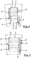
- Figure 4 shows an embodiment of a roof assembly in which the features of the invention are embodied.
- the signal electrode layer sections 8' are grouped into two different groups (in figure 4 two groups of four adjacent sections 8' each), wherein all signal electrode layer sections 8' of one group at corresponding ones of the section ends 11 or 12 are connected to respective signal electrode lines 5.
- the 'upper' group of sections 8' are connected to respective signal electrode lines 5 at their (lefthanded) section ends 11, whereas the 'lower' group of sections 8' are connected to respective signal electrode lines 5 at their (righthanded) section ends 12.
- the width of the two bundles of signal electrode lines 5 extending longitudinally along corresponding side edges of the roof assembly 1 can be minimized.
- the indications 'upper' and 'lower' merely relate to the orientation in the figure and not to a real orientation.
- the total number of sections 8' in the two different groups is equal (in this embodiment there is an even number of sections 8'). If the total number is uneven, it is preferred that one group contains only a single section 8' more than the other group. Further this embodiment has a single common electrode layer which requires a single common electrode line 4 (here connected to section end 11, but it also can be connected at any other convenient edge location of the roof assembly 1, for example a rearward edge, as illustrated at 4").
- Figure 5 shows an alternative arrangement of the sections, with two subgroups of adjacent sections 8' each having respective signal electrode lines 5 connected to the righthanded section ends 12, and a group of adjacent sections 8' positioned between the two subgroups and having respective signal electrode lines 5 connected to the lefthanded section ends 11.
- the common electrode line has not been illustrated, but again may be connected at any desired or appropriate edge location of the roof assembly 1.
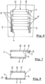
- FIG. 6 Yet another embodiment is illustrated in figure 6 in which the signal electrode layer sections 8' are arranged such that, as viewed in the longitudinal direction, signal electrode layer sections 8' belonging to one group (having the signal electrode lines 5 connected to section ends 11) and signal electrode layer sections 8' belonging to the other group (having the signal electrode lines 5 connected to opposite section ends 12) alternate.
- two common electrode lines 4 have been illustrated, which will connect to two separate common electrode layers (which together will define the common electrode layer 7).
- the or each common electrode line 4 will be connected to the common electrode layer (or layers) 7 at an edge location of the roof assembly 1 where no signal electrode line 5 connects to a section end 11 or 12.
- it may connect to a common electrode layer at a free section end (that means a section end where there is no connection to a signal line 5) or to a forward or rearward edge of the common electrode layer.
- Figure 7 schematically illustrates part of a transverse cross-section showing the constitutive layers of a roof assembly.
- a signal electrode line 5 is connected to a respective signal electrode layer 8
- the central electrically dimmable layer 6 the common electrode layer 7 and the support layer 9 on the common electrode layer are inwardly recessed.
- part of the signal electrode layer will be exposed and the signal electrode line 5 may be connected therewith by means of, for example, solder or a conductive paste 13. This also provides space for accommodating the signal electrode lines (and/or common electrode line(s)).
- the central electrically dimmable layer 6, the signal electrode layer 8 and the support layer 10 on the signal electrode layer 8 may be inwardly recessed at the edge location (here for example section end 11) where a common electrode line 4 is connected to the corresponding common electrode layer 7 (using, for example, solder or a conductive paste 13) .
- FIGS. 7 and 8 may be applied and combined in any convenient manner. For example, they both may define opposite ends of a section (but also a provision at other edge locations of the roof assembly is conceivable). But also, one of these arrangements may be provided at both ends of a section or at a forward and rearward edge of the roof assembly. Such an arrangement may extend over the entire length, but also over only a limited length in the longitudinal direction of the roof assembly.
Landscapes
- Physics & Mathematics (AREA)
- Nonlinear Science (AREA)
- General Physics & Mathematics (AREA)
- Optics & Photonics (AREA)
- Engineering & Computer Science (AREA)
- Mechanical Engineering (AREA)
- Liquid Crystal (AREA)
- Structure Of Printed Boards (AREA)
Abstract
A dimmable transparent roof assembly comprises a central electrically dimmable layer, a common electrode layer on one surface of the dimmable layer which is connected to a common electrode line, a signal electrode layer on the opposite surface of the dimmable layer and two support layers. The signal electrode layer, as seen in a longitudinal direction of the roof assembly, is divided into signal electrode layer sections each extending in a transverse direction between opposite section ends. The signal electrode layer sections are grouped into two different groups and all signal electrode layer sections of one group at corresponding ones of the section ends are connected to respective signal electrode lines. All signal electrode layer sections of the other group at corresponding opposite ones of the section ends are connected to respective signal electrode lines.
Description
- The invention relates to a dimmable transparent roof assembly intended for use in the roof of a vehicle, comprising a central electrically dimmable layer, a common electrode layer on one surface of the dimmable layer which is connected to a common electrode line, a signal electrode layer on the opposite surface of the dimmable layer and two support layers on the surfaces of the common electrode layer and of the signal electrode layer, respectively, facing away from the dimmable layer, wherein the signal electrode layer, as seen in a longitudinal direction of the roof assembly, is divided into signal electrode layer sections each extending in a transverse direction between opposite section ends.
- When in such a dimmable transparent roof assembly the number of signal electrode layer sections increases, the number of signal electrode lines increases correspondingly. This results in an increase of the overall width of the signal electrode lines, and beyond a certain number of sections, and thus signal electrode lines, such a width will be too much to accommodate in the roof assembly (such as, for example, under black out regions at side edges of the roof assembly).
- In accordance with the present invention the signal electrode layer sections are grouped into two different groups, wherein all signal electrode layer sections of one group at corresponding ones of the section ends are connected to respective signal electrode lines, whereas all signal electrode layer sections of the other group at corresponding opposite ones of the section ends are connected to respective signal electrode lines and wherein the signal electrode lines extend longitudinally along side edges of the roof assembly which correspond with the respective section ends.
- In such a configuration, the signal electrode lines no longer all extend at the same side edge, but are divided over the two side edges, thus limiting the overall width of the signal electrode lines extending at the same side edge, which allows to increase the daylight opening size of the roof assembly. Or, put in another manner, this allows an increase of the number of signal electrode layer sections without arriving at an unacceptable overall width of the signal electrode lines.
- In an embodiment of the dimmable transparent roof assembly the difference between the number of signal electrode layer sections in the two different groups is at most 1. In such an embodiment the number of signal electrode layer sections in the two different groups will be identical when there are an even number of sections, thus evenly dividing the signal electrode lines over both side edges of the roof assembly.
- The two different groups may be defined in many different manners. As non-limiting examples the following embodiments are mentioned: the signal electrode layer sections belonging to the same group are arranged adjacent each other, wherein the two different groups are positioned adjacent to each other as viewed in the longitudinal direction; the signal electrode layer sections belonging to one group are divided into two different subgroups each comprising signal electrode layer sections arranged adjacent each other, whereas the signal electrode layer sections belonging to the other group are arranged adjacent each other into a single group which, as viewed in the longitudinal direction, is positioned between the two subgroups; the signal electrode layer sections are arranged such that, as viewed in the longitudinal direction, signal electrode layer sections belonging to one group and signal electrode layer sections belonging to the other group alternate.
- In one embodiment of the dimmable transparent roof assembly according to the present invention, the central electrically dimmable layer, the common electrode layer and the support layer on the common electrode layer are inwardly recessed at the section ends where signal electrode lines are connected to the signal electrode layer sections.
- As a result, the signal electrode layer is locally exposed and is accessible for a connection to a respective signal electrode line, for example by applying solder or a conductive paste between the signal electrode layer and the signal electrode line. Further, such a recess results in sufficient space for accommodating the signal electrode lines (and possibly a common electrode line) extending longitudinally along the respective side edge of the roof assembly.
- Preferably, the common electrode line is connected to the common electrode layer at an edge location of the roof assembly where no signal electrode line connects to a section end. This allows to minimize the thickness of the roof assembly.
- The common electrode layer, which is common for at least a number of signal electrode layer sections, may be carried out in different ways. For example, it is conceivable that there is only one common electrode layer for all signal electrode layer sections. Thus, the roof assembly then has only one common electrode layer, which also needs only one common electrode line. The connection of such a single common electrode line to the single common electrode layer can occur at any of a number of different edge locations, but preferably, then, the common electrode line is connected to the common electrode layer at a forward or rearward edge of the roof assembly.
- In an alternative embodiment there is a separate common electrode layer for each group with its respective common electrode line. In such an embodiment it is possible that a common electrode line of a group is connected to a corresponding common electrode layer at a side edge of the roof assembly opposite the section ends to which the signal electrode lines of said group are connected, wherein said common electrode line extends longitudinally along said side edge. This allows a very convenient and optimized positioning of the common electrode lines with respect to the signal electrode lines.
- In one embodiment the central electrically dimmable layer, the signal electrode layer and the support layer on the signal electrode layer are inwardly recessed at the edge location where a common electrode line is connected to the corresponding common electrode layer. This makes the common electrode layer accessible for connection to the common electrode line and provides a space for accommodating the common electrode line (similar to what has been explained above with respect to inwardly recessing the central electrically dimmable layer, the common electrode layer and the support layer on the common electrode layer).
- In one embodiment the common electrode line(s) and/or the signal electrode lines are defined by flexible printed circuits. However, other structures, such as for example copper strips (or bus bars), are conceivable too.
- Hereinafter the invention will be elucidated while referring to the drawings, in which:
-
Figures 1 and 2 are a schematic top plan view and a schematic partial transverse cross-section, respectively, for illustrating the principles of a roof assembly, whereinfigure 2 is a cross-section according to II-II infigure 1 ; -
Figure 3 is a top plan view of a state of the art roof assembly; -
Figures 4-6 are top plan views of embodiments of the roof assembly according to the invention, and -
Figures 7 and 8 show partial transverse crosssections of embodiments of the roof assembly. -
Figures 1 and 2 are used to illustrate the basic features of a dimmabletransparent roof assembly 1 of the type intended for use in theroof 2 of a vehicle and subject of the present invention. Theroof assembly 1 may be used to cooperate with aroof opening 3 in theroof 2, and for its activation (switching between a dimmed and non-dimmed state) is electrically connected to acommon electrode line 4 and asignal electrode line 5 which may (and generally will) extend longitudinally along the roof assembly. - As illustrated in
figure 2 , such a dimmabletransparent roof assembly 1 basically comprises a central electricallydimmable layer 6, acommon electrode layer 7 to which thecommon electrode line 4 is connected (here this connection is only indicated schematically by a dotted section 4' of the common electrode line 4) on one (here lower) surface of thedimmable layer 6, asignal electrode layer 8 to which thesignal electrode line 5 is connected (here this connection is only indicated schematically by a dotted section 5' of the signal electrode line 5) on the opposite (here upper) surface of thedimmable layer 6 and twosupport layers common electrode layer 7 and of thesignal electrode layer 8, respectively. - It is noted that
figure 2 is not to scale and that in practice some or all layers may be very thin. Further it is noted, that in the embodiment according tofigure 1 there is only asingle electrode layer 8 extending over the entire extent of theroof assembly 1 which, thus, requires only a singlesignal electrode line 5. - Referring to
figure 3 a state of the art embodiment of such aroof assembly 1 is illustrated (theroof opening 3 is not shown) in which the signal electrode layer, as seen in a longitudinal direction of the roof assembly, is divided into a number of separate signal electrode layer sections 8' each extending in a transverse direction betweenopposite section ends 11 and 12 (only indicated for one section 8'). For an individual activation of these sections 8' an equal number of respectivesignal electrode lines 5 is required, which leads to a bundle ofsignal electrode lines 5 with a considerable width, of which the positioning in theroof assembly 1 may cause problems. -
Figure 4 shows an embodiment of a roof assembly in which the features of the invention are embodied. The signal electrode layer sections 8' are grouped into two different groups (infigure 4 two groups of four adjacent sections 8' each), wherein all signal electrode layer sections 8' of one group at corresponding ones of thesection ends signal electrode lines 5. Thus, infigure 4 the 'upper' group of sections 8' are connected to respectivesignal electrode lines 5 at their (lefthanded) section ends 11, whereas the 'lower' group of sections 8' are connected to respectivesignal electrode lines 5 at their (righthanded) section ends 12. Thus, the width of the two bundles ofsignal electrode lines 5 extending longitudinally along corresponding side edges of theroof assembly 1 can be minimized. It is noted that the indications 'upper' and 'lower' merely relate to the orientation in the figure and not to a real orientation. - In
figure 4 the total number of sections 8' in the two different groups is equal (in this embodiment there is an even number of sections 8'). If the total number is uneven, it is preferred that one group contains only a single section 8' more than the other group. Further this embodiment has a single common electrode layer which requires a single common electrode line 4 (here connected tosection end 11, but it also can be connected at any other convenient edge location of theroof assembly 1, for example a rearward edge, as illustrated at 4"). -
Figure 5 shows an alternative arrangement of the sections, with two subgroups of adjacent sections 8' each having respectivesignal electrode lines 5 connected to therighthanded section ends 12, and a group of adjacent sections 8' positioned between the two subgroups and having respectivesignal electrode lines 5 connected to thelefthanded section ends 11. The common electrode line has not been illustrated, but again may be connected at any desired or appropriate edge location of theroof assembly 1. - Yet another embodiment is illustrated in
figure 6 in which the signal electrode layer sections 8' are arranged such that, as viewed in the longitudinal direction, signal electrode layer sections 8' belonging to one group (having thesignal electrode lines 5 connected to section ends 11) and signal electrode layer sections 8' belonging to the other group (having thesignal electrode lines 5 connected to opposite section ends 12) alternate. Here twocommon electrode lines 4 have been illustrated, which will connect to two separate common electrode layers (which together will define the common electrode layer 7). Generally, the or eachcommon electrode line 4 will be connected to the common electrode layer (or layers) 7 at an edge location of theroof assembly 1 where nosignal electrode line 5 connects to asection end -
Figure 7 schematically illustrates part of a transverse cross-section showing the constitutive layers of a roof assembly. One can see that at a section end (here section end 12) where asignal electrode line 5 is connected to a respectivesignal electrode layer 8, the central electricallydimmable layer 6, thecommon electrode layer 7 and thesupport layer 9 on the common electrode layer are inwardly recessed. As a result, part of the signal electrode layer will be exposed and thesignal electrode line 5 may be connected therewith by means of, for example, solder or aconductive paste 13. This also provides space for accommodating the signal electrode lines (and/or common electrode line(s)). - In a similar manner (as illustrated in
figure 8 ) the central electricallydimmable layer 6, thesignal electrode layer 8 and thesupport layer 10 on thesignal electrode layer 8 may be inwardly recessed at the edge location (here for example section end 11) where acommon electrode line 4 is connected to the corresponding common electrode layer 7 (using, for example, solder or a conductive paste 13) . - The arrangements according to
figures 7 and 8 may be applied and combined in any convenient manner. For example, they both may define opposite ends of a section (but also a provision at other edge locations of the roof assembly is conceivable). But also, one of these arrangements may be provided at both ends of a section or at a forward and rearward edge of the roof assembly. Such an arrangement may extend over the entire length, but also over only a limited length in the longitudinal direction of the roof assembly. Thus, in a specific embodiment and referring tofigure 4 , it is conceivable that for the 'upper' group of sections 8' the central electricallydimmable layer 6, thecommon electrode layer 7 and thesupport layer 9 on the common electrode layer are inwardly recessed atsection ends 11, whereas for the 'lower' group of sections 8' the central electricallydimmable layer 6, thesignal electrode layer 8 and thesupport layer 10 on the common electrode layer are inwardly recessed at those section ends 11 (and wherein, for example, the central electricallydimmable layer 6, thecommon electrode layer 7 and thesupport layer 9 on the common electrode layer are inwardly recessed at thesection ends 12 of both groups, thus over the total length of the respective side edge of the roof assembly). - The invention is not limited to the described embodiments which may be varied widely within the scope of the invention as defined by the appending claims.
Claims (13)
- Dimmable transparent roof assembly intended for use in the roof of a vehicle, comprising a central electrically dimmable layer, a common electrode layer on one surface of the dimmable layer which is connected to a common electrode line, a signal electrode layer on the opposite surface of the dimmable layer and two support layers on the surfaces of the common electrode layer and of the signal electrode layer, respectively, facing away from the dimmable layer, wherein the signal electrode layer, as seen in a longitudinal direction of the roof assembly, is divided into signal electrode layer sections each extending in a transverse direction between opposite section ends, characterized in that the signal electrode layer sections are grouped into two different groups and wherein all signal electrode layer sections of one group at corresponding ones of the section ends are connected to respective signal electrode lines, whereas all signal electrode layer sections of the other group at corresponding opposite ones of the section ends are connected to respective signal electrode lines and wherein the signal electrode lines extend longitudinally along side edges of the roof assembly which correspond with the respective section ends.
- Dimmable transparent roof assembly according to claim 1, wherein the difference between the number of signal electrode layer sections in the two different groups is at most 1.
- Dimmable transparent roof assembly according to any of the previous claims, wherein the signal electrode layer sections belonging to the same group are arranged adjacent each other and wherein the two different groups are positioned adjacent to each other as viewed in the longitudinal direction.
- Dimmable transparent roof assembly according to claim 1 or 2, wherein the signal electrode layer sections belonging to one group are divided into two different subgroups each comprising signal electrode layer sections arranged adjacent each other, whereas the signal electrode layer sections belonging to the other group are arranged adjacent each other into a single group which, as viewed in the longitudinal direction, is positioned between the two subgroups.
- Dimmable transparent roof assembly according to claim 1 or 2, wherein the signal electrode layer sections are arranged such that, as viewed in the longitudinal direction, signal electrode layer sections belonging to one group and signal electrode layer sections belonging to the other group alternate.
- Dimmable transparent roof assembly according to any of the previous claims, wherein at the section ends where signal electrode lines are connected to the signal electrode layer sections, the central electrically dimmable layer, the common electrode layer and the support layer on the common electrode layer are inwardly recessed.
- Dimmable transparent roof assembly according to any of the previous claims, wherein the common electrode line is connected to the common electrode layer at an edge location of the roof assembly where no signal electrode line connects to a section end.
- Dimmable transparent roof assembly according to claim 7, wherein there is only one common electrode layer for all signal electrode layer sections.
- Dimmable transparent roof assembly according to claim 8, wherein the common electrode line is connected to the common electrode layer at a forward or rearward edge of the roof assembly.
- Dimmable transparent roof assembly according to claim 7, wherein there is a separate common electrode layer for each group with its respective common electrode line.
- Dimmable transparent roof assembly according to claim 10, wherein a common electrode line of a group is connected to a corresponding common electrode layer at a side edge of the roof assembly opposite the section ends to which the signal electrode lines of said group are connected and wherein said common electrode line extends longitudinally along said side edge.
- Dimmable transparent roof assembly according to any of the claims 7-11, wherein at the edge location where a common electrode line is connected to the corresponding common electrode layer the central electrically dimmable layer, the signal electrode layer and the support layer on the signal electrode layer are inwardly recessed.
- Dimmable transparent roof assembly according to any of the previous claims, wherein the common electrode line(s) and/or the signal electrode lines are defined by flexible printed circuits.
Priority Applications (2)
| Application Number | Priority Date | Filing Date | Title |
|---|---|---|---|
| EP21188651.0A EP4124485A1 (en) | 2021-07-30 | 2021-07-30 | Dimmable transparent roof assembly |
| CN202210888802.5A CN115675036A (en) | 2021-07-30 | 2022-07-27 | Light-adjustable transparent roof assembly |
Applications Claiming Priority (1)
| Application Number | Priority Date | Filing Date | Title |
|---|---|---|---|
| EP21188651.0A EP4124485A1 (en) | 2021-07-30 | 2021-07-30 | Dimmable transparent roof assembly |
Publications (1)
| Publication Number | Publication Date |
|---|---|
| EP4124485A1 true EP4124485A1 (en) | 2023-02-01 |
Family
ID=77465777
Family Applications (1)
| Application Number | Title | Priority Date | Filing Date |
|---|---|---|---|
| EP21188651.0A Withdrawn EP4124485A1 (en) | 2021-07-30 | 2021-07-30 | Dimmable transparent roof assembly |
Country Status (2)
| Country | Link |
|---|---|
| EP (1) | EP4124485A1 (en) |
| CN (1) | CN115675036A (en) |
Cited By (1)
| Publication number | Priority date | Publication date | Assignee | Title |
|---|---|---|---|---|
| DE102023112142A1 (en) * | 2023-05-09 | 2024-11-14 | Webasto SE | Switchable functional film and method for contacting a functional layer |
Citations (1)
| Publication number | Priority date | Publication date | Assignee | Title |
|---|---|---|---|---|
| WO2020083563A1 (en) * | 2018-10-26 | 2020-04-30 | Saint-Gobain Glass France | Composite pane, having a functional element that can be switched in segments and that has electrically controllable optical properties |
-
2021
- 2021-07-30 EP EP21188651.0A patent/EP4124485A1/en not_active Withdrawn
-
2022
- 2022-07-27 CN CN202210888802.5A patent/CN115675036A/en active Pending
Patent Citations (1)
| Publication number | Priority date | Publication date | Assignee | Title |
|---|---|---|---|---|
| WO2020083563A1 (en) * | 2018-10-26 | 2020-04-30 | Saint-Gobain Glass France | Composite pane, having a functional element that can be switched in segments and that has electrically controllable optical properties |
Cited By (1)
| Publication number | Priority date | Publication date | Assignee | Title |
|---|---|---|---|---|
| DE102023112142A1 (en) * | 2023-05-09 | 2024-11-14 | Webasto SE | Switchable functional film and method for contacting a functional layer |
Also Published As
| Publication number | Publication date |
|---|---|
| CN115675036A (en) | 2023-02-03 |
Similar Documents
| Publication | Publication Date | Title |
|---|---|---|
| EP3595042B1 (en) | Circuit body and battery module | |
| US3819417A (en) | Mechanically interlaced and electrically interconnected silicon solar cells | |
| US4654967A (en) | Method and device for aligning and straightening flexible, insulated conductors | |
| EP0170480A2 (en) | Flexible electrical connectors | |
| US7955123B2 (en) | Cell connector for electronically contacting planar power sources, and use thereof | |
| US4902236A (en) | Flex circuit and cable assembly | |
| EP4124485A1 (en) | Dimmable transparent roof assembly | |
| CN114583401A (en) | Battery connection module | |
| US6843660B2 (en) | Cable systems and related methods | |
| DE1263844B (en) | Fastening device for magnet wire memory | |
| US4568796A (en) | Housing carrier for integrated circuit | |
| US3320488A (en) | Strip line power harness | |
| EP0147045A2 (en) | Membrane type circuit having improved tail | |
| US4643497A (en) | Device and method for connecting a printed circuit film | |
| KR102817789B1 (en) | Lighting fixture | |
| KR950005580B1 (en) | Flat cathode ray tube having flexible, wooven conductor | |
| US7227443B2 (en) | Fixed network resistor | |
| US20230395878A1 (en) | Battery monitoring module and flexible printed wiring board | |
| US3740693A (en) | Bus bar with integral terminals | |
| CN212115785U (en) | PCB jointed board | |
| EP1026927A2 (en) | Special bond pad configurations for printed circuit boards | |
| DE102009015224A1 (en) | LED light source with a variety of LED chips and LED chip for use in same | |
| CN221149099U (en) | Adapter plate structure, backlight LED driving structure and liquid crystal display screen | |
| JPH0846310A (en) | Flexible wiring board | |
| CN219936623U (en) | Display panel splicing unit |
Legal Events
| Date | Code | Title | Description |
|---|---|---|---|
| PUAI | Public reference made under article 153(3) epc to a published international application that has entered the european phase |
Free format text: ORIGINAL CODE: 0009012 |
|
| STAA | Information on the status of an ep patent application or granted ep patent |
Free format text: STATUS: THE APPLICATION HAS BEEN PUBLISHED |
|
| AK | Designated contracting states |
Kind code of ref document: A1 Designated state(s): AL AT BE BG CH CY CZ DE DK EE ES FI FR GB GR HR HU IE IS IT LI LT LU LV MC MK MT NL NO PL PT RO RS SE SI SK SM TR |
|
| STAA | Information on the status of an ep patent application or granted ep patent |
Free format text: STATUS: THE APPLICATION IS DEEMED TO BE WITHDRAWN |
|
| 18D | Application deemed to be withdrawn |
Effective date: 20230802 |