EP4124422A1 - Personal care device - Google Patents
Personal care device Download PDFInfo
- Publication number
- EP4124422A1 EP4124422A1 EP21188505.8A EP21188505A EP4124422A1 EP 4124422 A1 EP4124422 A1 EP 4124422A1 EP 21188505 A EP21188505 A EP 21188505A EP 4124422 A1 EP4124422 A1 EP 4124422A1
- Authority
- EP
- European Patent Office
- Prior art keywords
- working head
- personal care
- adjustment
- care device
- adjustment actuator
- Prior art date
- Legal status (The legal status is an assumption and is not a legal conclusion. Google has not performed a legal analysis and makes no representation as to the accuracy of the status listed.)
- Granted
Links
Images




Classifications
-
- B—PERFORMING OPERATIONS; TRANSPORTING
- B26—HAND CUTTING TOOLS; CUTTING; SEVERING
- B26B—HAND-HELD CUTTING TOOLS NOT OTHERWISE PROVIDED FOR
- B26B19/00—Clippers or shavers operating with a plurality of cutting edges, e.g. hair clippers, dry shavers
- B26B19/38—Details of, or accessories for, hair clippers, or dry shavers, e.g. housings, casings, grips, guards
- B26B19/3873—Electric features; Charging; Computing devices
- B26B19/388—Sensors; Control
-
- B—PERFORMING OPERATIONS; TRANSPORTING
- B26—HAND CUTTING TOOLS; CUTTING; SEVERING
- B26B—HAND-HELD CUTTING TOOLS NOT OTHERWISE PROVIDED FOR
- B26B19/00—Clippers or shavers operating with a plurality of cutting edges, e.g. hair clippers, dry shavers
- B26B19/02—Clippers or shavers operating with a plurality of cutting edges, e.g. hair clippers, dry shavers of the reciprocating-cutter type
- B26B19/04—Cutting heads therefor; Cutters therefor; Securing equipment thereof
- B26B19/048—Complete cutting head being movable
-
- B—PERFORMING OPERATIONS; TRANSPORTING
- B26—HAND CUTTING TOOLS; CUTTING; SEVERING
- B26B—HAND-HELD CUTTING TOOLS NOT OTHERWISE PROVIDED FOR
- B26B19/00—Clippers or shavers operating with a plurality of cutting edges, e.g. hair clippers, dry shavers
- B26B19/02—Clippers or shavers operating with a plurality of cutting edges, e.g. hair clippers, dry shavers of the reciprocating-cutter type
- B26B19/04—Cutting heads therefor; Cutters therefor; Securing equipment thereof
- B26B19/06—Cutting heads therefor; Cutters therefor; Securing equipment thereof involving co-operating cutting elements both of which have shearing teeth
- B26B19/063—Movable or adjustable cutting head
Definitions
- the present invention relates to a personal care device, in particular hair removal device such as an electric shaver, comprising an elongated handle for manually moving the personal care device along a body surface, a working head attached to said handle for effecting a personal care treatment to said body surface, wherein an adjustment device including at least one adjustment actuator is provided for adjusting a treatment characteristic of said personal care device such as the adaptivity of the working head.
- Personal care devices are widely used to apply different types of personal care treatments to users, wherein such personal care devices may include hair removal devices such as epilators, shavers or razors which may be electric or manual and/or wet or dry, or beard trimmers.
- other personal care devices include dental care appliances such as electric or manual tooth brushes, interdental cleaners or gum massaging devices, or skin treatment devices such as massaging devices or vibrators. All such personal care devices are subject to the problem that different users use the personal care devices in different ways and different users have different preferences for the mechanical settings of the personal care device.
- the working head should provide for a softer or more controllable or stiffer user feeling what requires different movability characteristics of the suspension allowing for movements of the working head relative to the handle and/or movements of the working head element relative to the working head base.
- Changing the movability characteristics also may be desirable for the same user when using the personal care device in different treatment modes, in different shaving situations or at different body portions. For example, when shaving the upper lip region below the nose, short strokes are made and more control is desired so working head stiffness should be increased, whereas shaving the cheeks or the region around the adam's apple may require less stiffness and/or a wider pivoting/swiveling range to achieve better contour adaption.
- the suspension of the working head relative to the handle and/or the suspension of the working head element relative to a working head base may allow for various types of movements of the working head and the working head element, respectively, such as rotatory movements and/or linear movements thereof.
- the working head may tilt and/or swivel relative to the elongated handle, wherein a tilt axis and a swivel axis may extend substantially parallel to the skin contact surface of the working head and transverse to each other.
- the working head may dive or float relative to the handle along a diving axis substantially perpendicular to the skin contact surface and/or substantially parallel to the longitudinal axis of the handle.
- a working head element such as a shear foil cartridge of a shaver may tilt and/or swivel and/or dive relative to the working head frame or working head base to allow adaption to the skin contour.
- the suspension of the working head and/or the suspension of the working head element relative to the working head base may be adjusted to change the characteristics of the adjusting movements of the working head and/or the working head element.
- the tilting and/or swiveling and/or diving stiffness may be increased or decreased to provide for a more controllable / stiffer (or aggressive) or a softer characteristic of the adjustment movements.
- the tilting and/or swiveling and/or diving range in terms of the maximum rotatory and/or linear displacement may be varied.
- EP 3 546 153 B1 shows an electric shaver having a pivotable suspension of its working head to allow for pivoting of the working head relative to the handle and a diving suspension of the shear foil cartridge to allow for diving of the shear foil cartridge relative to the working head frame.
- the pivoting stiffness of the working head and the diving stiffness of the shear foil cartridge are controlled by means of mechanical springs which can be adjusted by means of actuators so as to increase and decrease pivoting stiffness and diving stiffness in terms of the torque and force necessary to achieve a certain pivot angle and a certain diving displacement.
- the adjustment mechanism is configured to adjust the angular pivoting range of the working head to allow a larger or smaller maximum angular displacement.
- Another option of adjusting the treatment characteristic is adjustment of the cutting length of a hair trimmer, wherein for example document WO 2018/069265 A1 discloses a hair trimmer including an adjustment actuator for adjusting the cutting length of the trimmer.
- a more particular objective underlying the invention is to provide for an improved adjustment of the personal care device to the user and varying use situations.
- Another objective underlying the invention is to achieve self-adaption of the personal care device to the user's habits and preferences and/or to the treatment conditions in a way comfortable to the user and, at the same time, efficiently improving the treatment process.
- a further objective underlying the invention is to provide for an improved personal care device quickly achieving adaption to varying body surface contours and treatment regions without irritating the user.
- a still further objective underlying the invention is to achieve efficient self-adjusting with reduced energy consumption and a light-weight structure to improve handling of the personal care device due to less weight to be handled.
- an adjustment actuator which is configured and controlled to achieve a smooth transition between different settings of the treatment characteristics. More particularly, the adjustment actuator may be configured and controlled to adjust the treatment characteristic from a first setting to a second setting within a time period of not less than 0.1 seconds and not more than 1.5 seconds. Advantageously, the adjustment actuator may be configured and controlled to achieve transition between the two settings within a time period of not less than 0.15 seconds and not more than 0.5 seconds or a transition time period of not less than 0.15 seconds and not more than 0.25 seconds.
- a personal care device in particular hair removal device such as an electric shaver, comprising an elongated handle for manually moving the personal care device along a body surface, a working head attached to said handle, said working head having at least one working head element for effecting a personal care treatment to said body surface, wherein an adjustment device including at least one adjustment actuator is provided for adjusting at least one treatment characteristic.
- hair removal device such as an electric shaver
- the adjustment actuator is operated with a limited change rate so the transition from one state such as "soft” to another one such as "hard” happens within a well-defined time duration.
- transition should not be too fast because immediate changes could disturb the user or could be considered as uncomfortable to the user experience.
- the transition should be fast enough to arrive at the desired setting of the treatment characteristic in response to variations of the treatment region and/or variations of the way of using the personal care device such as changing from short strokes to long strokes.
- the adjustment actuator may be configured and controlled to effect the transition from a first setting to a second setting of the treatment characteristics within a transition time not exceeding the time spent for one or two strokes.
- the adjustment actuator may be configured to allow operation at different speeds, wherein a control unit for controlling the adjustment actuator may be configured to vary the transition time spent for effecting the adjustment, i.e. transition from a first setting to a second setting depending on user habits and/or preferences and/or operational situations. For example, when changing from long stroke use to short stroke use, it may be advantageous to effect transition from, for example, a softer working head configuration to a harder working head configuration within a shorter transition time of, for example, 0.15 to 0.20 seconds, whereas, on the other hand, it may be advantageous to effect transition from the harder setting to the softer setting, when changing from short-stroke operation to long-stroke operation, within a longer transition time period of, for example, 0.20 seconds to 0.25 seconds.
- transition speed may be reduced at an initial phase and/or at an end phase of the transition, whereas transition speed may be increased at a medium phase of the transition.
- the adjustment actuator may be under control of an electronic control unit and/or responsive to electronic control commands.
- the adjustment actuator may include an electric motor which may displace an adjustment element such as a spring bearing of a spring element influencing stiffness of the movable working head and/or a range limiter, wherein a gearing may be provided between said electric motor and the adjustment element to transmit the drive motion of the electric motor to the adjustment element.
- an electric motor which may be combined with a gear box, allows for easy and precise control of the adjustment action and, at the same time, easy variation of the transition speed.
- the adjustment actuator also may include a smart material changing a material property to control the adjustment, when subject to a control signal and/or subject to predefined ambient conditions.
- the adjustment actuator may include a smart fluid changing its viscosity when subject to a magnetic field and/or an electric field, wherein such smart fluid may cooperate with an adjustment element to change the displacement resistance thereof.
- the adjustment actuator may include a smart metal such as a bimetal changing its shape when subject to heating and/or cooling.
- the adjustment actuator may change various treatment characteristics.
- adaptivity of the working head and/or of a working head element may be adjusted, for example movability of the working head relative to the handle and/or movability of the working head element relative to a working head base to allow adaption of the personal care device to the body surface to be treated.
- rotatory and/or linear stiffness and/or rotatory and/or linear displacement range of the working head and/or of a working head element may be adjusted by the adjustment actuator.
- the personal care device may include a main drive unit for driving a main functional aggregate such as a drive motor for driving cutting tools of, for example a shaver.
- the adjustment actuator may be different from and/or additional to such main drive unit.
- the working head of the personal care device may be movably supported relative to the handle thereof and/or include a working head element being movably supported relative to a working head base to allow adaption of the working head and/or the working head element to the body surface contour, wherein the at least one adjustment actuator may adjust rotatory and/or linear displacement stiffness of said working head and/or the working head element.
- the adjustment actuator may be configured for varying the moving resistance of the movable working head and/or of the movable working head element in dependency of the moving speed and/or of angular and/or linear position of the working head and/or the working head element.
- Moving speed is here to be understood as the velocity, linear or rotatorily, of the working head element relative to the working head or of the working head relative to the handle of the device. Accordingly, the moving resistance is about forces or torques of this relative movement between different parts of the device.
- the graph defining the relationship between the force and/or torque necessary to move the working head and/or the working head element, and the moving speed can be varied by means of said actuator so as to, for example, increase or decrease the force and/or torque necessary to move the working head and/or the working head element at a certain speed relative to the handle/the working head base.
- the force and/or torque necessary to tilt and/or swivel the working head at a certain rotatory speed may be increased or decreased to achieve a higher or lower rotatory stiffness, wherein different rotatory stiffnesses may be provided for different rotatory speeds.
- the adjustment actuator for varying the moving resistance depending on moving speed as mentioned above or for varying the force or torque of the moveability of the working head or a working head element may be configured to adjust and/or vary the shape of the graph defining moving resistance over moving speed (or force or torque to be applied for movability) of the working head and/or working head element, wherein for example, the adjustment actuator may be configured to vary the curvature of such graph and/or to vary the shape of such graph from linear to non-linear and/or to vary the ratio of linear portions to non-linear portions and/or to vary the steepness of certain portions.
- Such adjustment actuator for varying the moving resistance depending on moving speed may include a viscose type of friction device which may include a fluid pusher to push away a viscose fluid when moving.
- a smart viscose fluid may be used which is configured to change its viscosity when subject to a magnetic field and/or electric field or voltage to allow for quick changes of viscosity to allow for adjustments within the current shave situation.
- Such viscose friction device may provide for a moving resistance increasing with moving speed.
- such viscose friction device may include an adjustable damper configured to provide varying damping forces.
- At least one adjustment actuator may be provided for varying the shape of a graph defining the restoring force and/or restoring torque of a restoring device over rotatory and/or linear displacement of the working head and/or working head element from a linear shape to a curved shape and/or the ratio of linear portions to non-linear portions of said graph.
- the restoring device for urging the working head and/or the working head element towards a desired neutral position may include at least one leaf spring connected to the working head and/or the working head element, wherein the adjustment actuator may be configured to change the effective length of such leaf spring.
- the adjustment actuator which is configured and controlled to achieve a smooth transition between different settings of the treatment characteristics. More particularly, the adjustment actuator may be configured and controlled to adjust the treatment characteristic from a first setting to a second setting within a time period of not less than 0.1 seconds and not more than 1.5 seconds.
- the adjustment actuator may be configured and controlled to achieve transition between the two settings within a time period of not less than 0.15 seconds and not more than 0.5 seconds or a transition time period of not less than 0.15 seconds and not more than 0.25 seconds.
- the adjustment actuator is operated with a limited change rate so the transition from one state such as "soft” to another one such as "hard” happens within a well-defined time duration.
- transition should not be too fast because immediate changes could disturb the user.
- the transition should be fast enough to get the setting of the treatment characteristic much with variations of the treatment region and/or variations of the way of using the personal care device such as changing from short strokes to long strokes.
- the adjustment actuator may be configured and controlled to effect the transition from a first setting to a second setting of the treatment characteristics within one or two strokes.
- the adjustment actuator may be configured to allow operation at different speeds, wherein a control unit for controlling the adjustment actuator may be configured to vary the transition time spent for effecting the adjustment, i.e. transition from a first setting to a second setting depending on user habits and/or preferences and/or operational situations. For example, when changing from long stroke use to short stroke use, it may be advantageous to effect transition from, for example, a softer working head configuration to a harder working head configuration within a shorter transition time of, for example, 0.15 to 0.20 seconds, whereas, on the other hand, it may be advantageous to effect transition from the harder setting to the softer setting, when changing from short-stroke operation to long-stroke operation, within a longer transition time period of, for example, 0.20 seconds to 0.25 seconds.
- transition speed may be reduced at an initial phase and/or at an end phase of the transition, whereas transition speed may be increased at a medium phase of the transition.
- the adjustment actuator may be under control of an electronic control unit and/or responsive to electronic control commands.
- the adjustment actuator may include an electric motor which may displace an adjustment element such as a spring bearing of a spring element influencing stiffness of the movable working head and/or a range limiter, wherein a gearing may be provided between said electric motor and the adjustment element to transmit the drive motion of the electric motor to the adjustment element.
- an electric motor which may be combined with a gear box, allows for easy and precise control of the adjustment action and, at the same time, easy variation of the transition speed.
- the adjustment actuator also may include a smart material changing a material property to control the adjustment, when subject to a control signal and/or subject to predefined ambient conditions.
- the adjustment actuator may include a smart fluid changing its viscosity when subject to a magnetic field and/or an electric field, wherein such smart fluid may cooperate with an adjustment element to change the displacement resistance thereof.
- Such adjustment actuator may be provided for varying the moving resistance depending on moving speed and/or may include a viscose type of friction device which may include a fluid pusher to push away a viscose fluid when moving.
- a smart viscose fluid may be used which is configured to change its viscosity when subject to a magnetic field and/or electric current to allow for quick changes of viscosity to allow for adjustments during one round of personal care treatment.
- Such viscose friction device may provide for a moving resistance increasing with moving speed. More particularly, such viscose friction device may include an adjustable damper configured to provide varying damping forces.
- the adjustment actuator may include a smart metal such as a bimetal changing its shape when subject to heating and/or cooling.
- At least one adjustment actuator may be provided for varying a breaking resistance counteracting and/or braking movement of the working head and/or the working head element irrespective of the direction thereof. Contrary to biasing devices such as preloading springs urging the working head towards a certain position, such braking resistance counteracts and/or brakes the working head and/or working head element moving in either direction. In other words, the direction of the braking force changes with the direction of the movement of the working head and/or working head element to always counteract such movements.
- the adjustment device may include a restoring for urging the working head and/or the working head element towards a desired neutral position, wherein such restoring device may include at least one spring element such as a leaf spring connected to the working head and/or the working head element, wherein the adjustment actuator may be configured to change the effective length of such leaf spring.
- a restoring device may include at least one spring element such as a leaf spring connected to the working head and/or the working head element, wherein the adjustment actuator may be configured to change the effective length of such leaf spring.
- the personal care device 20 includes an elongated handle 2 to be gripped by the fingers of a user to move the personal care device 20 along a body surface to be treated.
- Said handle 2 may form a housing in which functional and/or structural parts of the personal care device 20 may be accommodated, for example an energy storage such as a battery, a drive motor and/or a control unit for controlling the function such as a microprocessor with a program storage connected thereto.
- a working head 1 supported on said handle 2 includes one or more working head elements 7 for performing the care treatment.
- said working head element 7 may include hair cutting elements such as shear foil cartridges and/or a rake-like trimmer, cf. figure 2 .
- the working head element 7 may define a skin contact surface 17 of the working head 1, wherein said skin contact surface 17 may extend substantially perpendicular to a longitudinal axis of the handle 2 or inclined thereto, depending on the rotatory position of the working head 1.
- the skin contact surface 17 may be formed by a distal end side of the working head 1.
- the working head 1 may be supported on the handle 2, by means of a suspension 18, in a movable manner so that the working head 1 may be rotated and/or linearly displaced relative to the handle 2.
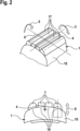
- the suspension 18 may allow for swiveling 3 of the working head 1 about a swivel axis 4, cf. figure 2 , and/or tilting 5 of the working head 1 about a tilt axis 6.
- Said swivel and tilt axes 4 and 6 may extend substantially perpendicular to each other and/or substantially parallel to the aforementioned skin contact surface 17, cf. figure 2 .
- the working head 1 also may be linearly displaced relative to the handle 2, for example along a displacement axis substantially parallel to the longitudinal axis of the handle 2 so that the working head 1, as a whole, may dive or float when the skin contact surface 17 is pressed against the body surface.
- one or more working heads 7 such as the aforementioned shear foil cartridges, may be movably supported relative to a working head base 10 by means of a suspension 19.
- the working head base 10 may form a frame-like structure which may swivel and/or tilt relative to the handle 2 in the aforementioned manner so that the additional movability of the working head element 7 may be superposed to the movability of the working head base 10.
- the working head elements 7 may be linearly displaced along a displacement axis 8 which may extend substantially perpendicular to the skin contact surface 17 so that the working head element 7 may dive or float when subject to skin contact pressure.
- the suspension 19 of the working head element 7 also may allow for rotatory movements of the working head elements 7 relative to the working head base 10 to allow for adaption of the working head element 7 to the skin contour.
- the working head element 7 may tilt along a tilt axis parallel to tilt axis 6of working head 1.
- the adaptive movements of the working head 1 and/or the working head element 7 to the skin contour may be controlled by an adaption controller 24 which may include one or more mechanisms and/or actuators and/or mechanical controllers to influence one or more of the aforementioned movements.
- the adaption controller 24 may include a restoring device 25 applying a restoring force and/or torque onto the working head 1 to urge the working head 1 towards a neutral or starting position which may be an intermediate position from which the working head 1 may move into opposite directions.
- the neutral or start position may be an end position at the swivel or tilt range.
- the restoring device 25 may be configured to urge the working head 1 into a neutral swivel position about swivel axis 4.
- Said restoring device 25 may include a leaf spring 31 connected or rigidly fixed to the working head base 10 in a way such that swivel 3 of the working head 1 causes the leaf spring 31 to pivot and thus, bend.
- leaf spring 31 is also connected to the handle 2 or a structural element fixed to said handle 2, by means of a spring bearing 32 which limits rotatory movements of the leaf spring 31 due to swiveling of the working head 1.
- the effective length 33 of the leaf spring 31 may be adjusted, wherein, for example, the aforementioned spring bearing 32 may be displaced in a direction substantially parallel to the longitudinal axis of the leaf spring 31.
- the spring bearing 32 may be displaced in a direction parallel to the longitudinal axis of the handle 2, cf. figure 5 , to change the effective length 33 of leaf spring 31.
- Displacement of the spring bearing 32 may be effected by means of an adjustment actuator 35 which can be controlled by the aforementioned control unit.
- said actuator 35 may include a motor 36 such as an electric motor which is connected to the displaceable spring bearing 32 via a drive train or connector or transmitter 34 transmitting the drive movement of the motor 36 to the spring bearing 32.
- Said motor 36 may be a DC motor.
- a gearing 37 may be provided between a drive shaft of motor 36 and transmitter 34 so as to transform, for example, a rotatory drive shaft movement into a substantially linear displacement of the spring bearing 32.
- the change rate of the active element in terms of said displaceable spring bearing 32 can be understood as a velocity of some actuator mechanics. It may move from one position to another one within a transition time duration that is not perceived as a sudden disturbing movement.
- an electronic control unit 39 which may include a microprocessor and a storage unit for storing a control software, may drives said motor 36 via suitable power electronics.
- controller and suitable electronics may be built up in a way that it can drive the motor 36 in both directions and with variable speed.
- the motor current may be measured by the controller. This can be done via a shunt resistor, i.e. a resistor that the motor current flows through and the measurement of the voltage across this resistor.
- a shunt resistor i.e. a resistor that the motor current flows through and the measurement of the voltage across this resistor.
- the gearing 37 may be built up with cogwheels.
- the gearing could be built up differently as well, e.g. it may include a worm gear, cf. figure 5 , or a gearing of the type harmonic drive. By at least one of those gearings, it may be possible to prevent movement without actuation which allows self-blocking of the gearing.
- the last stage 38 of the gearing may drive a transmitter such as a lever 34 that is attached to some connector such as the spring bearing 32 or more generally, an element that is able to adjust a property of the head such as the range limiter shown in Fig. 5 .
- the element also could be a spring, attached to some point at the pivotable head and adjusting its stiffness against rotations.
- the positions of the lever 34 correspond to different values of the head stiffness.
- the positions of the lever 34 include 2 end positions, a lower position and an upper position, and may include further positions in-between.
- the adjustment actuator may be stopped and held at various positions including at least one intermediate position between two end positions to allow for fine adjustment. More particularly, the adjustment actuator may be continuously and/or step-by-step operated and stopped at various desired positions to provide for continuous and/or step-by-step adaption of the treatment characteristic.
- the lower position may be used for adjusting the head to low stiffness and the upper position may be used for adjusting the head to high stiffness, cf. Fig. 3 .
- a detection device may be provided for detecting the end positions of the lever 34, wherein said detection device may include one or more of the following:
- the controller may drive the motor in the corresponding direction until the end position is detected.
- the controller drives the motor for a defined amount of time into the desired direction.
- the defined amount of time is derived from the needed movement distance and the velocity of the lever. This velocity can be assumed as constant or, for more accuracy, it can be estimated via the motor current. Higher current corresponds to lower motor velocity.
- the controller increases the speed of the motor 36 with a defined rate at the beginning of the motion and also slows down the motor with a defined rate at the end. Any sudden starting or stopping of the motor 36 is avoided in this way.
- the restoring device 35 may be configured such that the aforementioned leaf spring 31 is undeflected and/or straight when the working head 1 is in its neutral position. Thus, no torque and/or restoring force is applied to working head 1 when the later is in its neutral position. In other words, when starting displacement of the working head 1 out of its neutral position, substantially no torque and/or force is necessary so swiveling 3 may start at substantially zero resistance at the neutral position.
- the swiveling and/or tilting torque may increase with increasing swivel and/or tilt angles in a non-linear way. The larger the swivel or tilt angle gets, the steeper the torque increase may become.
- the torque characteristic also may be a linear one, wherein the resistive and/or restoring torque may linearly increase with an increasing swivel or tilt angle. Again, swivel or tilt stiffness may be adjusted also in case of a linear characteristic.
- a restoring device including a leaf spring similar as the restoring device 25 may be employed, wherein for example the leaf spring, with its longitudinal axis, may be arranged transverse to the diving axis 8 to be deflected when the working head element dives.
- adjusting diving stiffness may be achieved by increasing and/or decreasing the effective length of such leaf spring.
- other restoring devices including other types of springs such as a compression spring may be used to influence the diving characteristics, wherein for example the spring bearing may be displaced along the axis of compression.
- contour adaption movements of the working head 1 also may be controlled by a displacement range limiter 58 which may limit the available maximum rotatory and/or linear displacement.
- the displacement range limiter 58 may limit the maximum swiveling 3 of working head 1.
- an actuator 50..54 is used to push a wedge 55 into a gap 56 at the bottom of the shaving head 1.
- the swivel range is more or less limited.
- the swivel rotation has a wide range. With upward moving wedge, the range becomes smaller until the swivel rotation is completely blocked when the wedge is moved to its upper mechanical limit. The head is then forced into a predefined position.
- the adjustment actuator may work as follows: a motor 50 such as a DC-motor may turn a gear 51, which drives a second gear 52. This gear 52 contains an internal thread 53 and is placed on a threaded rod 54.
- the threaded rod is moved up and down, as soon as the motor 50 turns.
- the minimum- 41 and maximum- 42 angles of the head swiveling can be adjusted with the help of the motor 50.
- the motor 50 may be stopped and held at intermediate positions to define intermediate rotatory displacement ranges smaller than the maximum range and larger than the minimum range (which may be zero or larger than zero).
- the adjustment actuator may include a smart material such as a bimetal strip or bar for effecting the adjustment movement of the adjustment element.
- different types of smart materials may be used for implementing the adjustment actuator, such as materials changing their properties under the influence of ambient conditions, such as temperature, electric field, magnetic field, light and/or chemistry.
- a piece 120 of material that bends differently, depending on the temperature may be chosen. This can be a piece of bimetal.
- such piece 120 may be a rod or bar and/or may be rigidly supported at one end to allow for bending and/or deflection and thus, movement of the other end.
- the smart material in a first configuration, may bend in a way that it holds the lever 34 in its lower position.
- Some heating means such as an electrical resistor 121 may be activated to apply heating to the bimetal piece 120, wherein an electrical current may be forced to flow through the resistor.
- an electrical current may be forced to flow through the resistor.
- a maximum current and maximum temperature moves the lever 34 to the upper position ( Fig.7 ) and smaller amounts of heating move it to intermediate positions.
- the limited velocity is obtained by the heat capacitance of the piece of smart material and the power that is used to heat it up. So, it just needs time to get heated up.
- the limited velocity is obtained by the combination of the heat capacitance and the cooling that the piece of smart material experiences in its surrounding.
- Fig. 9 Another example of a set-up with a smart material is shown by Fig. 9 .
- the difference between different states of the mechanism is not a different position, but a difference in mechanical resistance or stiffness.
- Mechanical resistance may be understood as a quantity that relates the force that is needed to move a mechanical part with the velocity that is achieved by applying this force. It can also be understood as the ratio of such a force and such a velocity.
- a viscose type of friction device 100 may include a fluid pusher for pushing a viscose fluid away when the working head 1 and/or working head element 7 moves to adapt to the body surface contour.
- a smart viscose fluid may be used which is configured to change its viscosity when subject to a magnetic field and/or subject to electric current.
- a connecting rod 101 moves the element 102 up and down synchronously with the swivel rotation of the head.
- This element 102 acts as an inner damper element.
- This inner damper element is located inside the outer damping element 103.
- the space between inner and outer damping is filled with a magnetic liquid 104.
- the magnetic liquid is located between the poles of an electromagnet consisting of an iron core 105 and one or more coils 106.
- the viscosity of the magnetic liquid 104 is modified with the help of an electrical current through the coil(s) 106.
- the coil(s) Depending on the current, the coil(s) generate a magnetic field in the volume of the magnetic liquid 104. The higher the magnetic field, the higher is the viscosity of the magnetic liquid. A higher level of damping is then perceived by the user when the head is swiveled. If the current through the coil 106 is lowered, the characteristics is modified towards the curve 31. In summary, the current through the coil 106 controls the torque, needed to swivel the head 1 with a specific rotation speed.
- the strength of the field changing viscosity may be controlled by an electric control unit 107.
- the electrical field is controlled in such a way that it changes with a defined rate.
- the electronic control 107 can adjust this relation in a way that the head can pivot more or less easily and the transition is not perceived as an unexpected sudden resistance.
Landscapes
- Life Sciences & Earth Sciences (AREA)
- Forests & Forestry (AREA)
- Engineering & Computer Science (AREA)
- Mechanical Engineering (AREA)
- Dry Shavers And Clippers (AREA)
- Percussion Or Vibration Massage (AREA)
Abstract
Description
- The present invention relates to a personal care device, in particular hair removal device such as an electric shaver, comprising an elongated handle for manually moving the personal care device along a body surface, a working head attached to said handle for effecting a personal care treatment to said body surface, wherein an adjustment device including at least one adjustment actuator is provided for adjusting a treatment characteristic of said personal care device such as the adaptivity of the working head..
- Personal care devices are widely used to apply different types of personal care treatments to users, wherein such personal care devices may include hair removal devices such as epilators, shavers or razors which may be electric or manual and/or wet or dry, or beard trimmers. Furthermore, other personal care devices include dental care appliances such as electric or manual tooth brushes, interdental cleaners or gum massaging devices, or skin treatment devices such as massaging devices or vibrators. All such personal care devices are subject to the problem that different users use the personal care devices in different ways and different users have different preferences for the mechanical settings of the personal care device.
- In a more general context, some users tend to rather strongly press the working head against the body surface to be treated, whereas other users apply rather slight pressure. Some users tend to move the working head over the body surface at rather fast speeds in rather short strokes, whereas other users apply slower speeds and longer strokes. Depending on the user habits and preferences, the working head should provide for a softer or more controllable or stiffer user feeling what requires different movability characteristics of the suspension allowing for movements of the working head relative to the handle and/or movements of the working head element relative to the working head base.
- Changing the movability characteristics also may be desirable for the same user when using the personal care device in different treatment modes, in different shaving situations or at different body portions. For example, when shaving the upper lip region below the nose, short strokes are made and more control is desired so working head stiffness should be increased, whereas shaving the cheeks or the region around the adam's apple may require less stiffness and/or a wider pivoting/swiveling range to achieve better contour adaption.
- To allow for contour adaptions, i.e. adaption of a skin contact surface of the working head to the contour of the body portion to be treated, the suspension of the working head relative to the handle and/or the suspension of the working head element relative to a working head base may allow for various types of movements of the working head and the working head element, respectively, such as rotatory movements and/or linear movements thereof. More particularly, the working head may tilt and/or swivel relative to the elongated handle, wherein a tilt axis and a swivel axis may extend substantially parallel to the skin contact surface of the working head and transverse to each other. In addition or in the alternative, the working head may dive or float relative to the handle along a diving axis substantially perpendicular to the skin contact surface and/or substantially parallel to the longitudinal axis of the handle. Similarly, a working head element such as a shear foil cartridge of a shaver may tilt and/or swivel and/or dive relative to the working head frame or working head base to allow adaption to the skin contour.
- So as to meet different users' habits and preferences, the suspension of the working head and/or the suspension of the working head element relative to the working head base may be adjusted to change the characteristics of the adjusting movements of the working head and/or the working head element. For example, the tilting and/or swiveling and/or diving stiffness may be increased or decreased to provide for a more controllable / stiffer (or aggressive) or a softer characteristic of the adjustment movements. Furthermore, also the tilting and/or swiveling and/or diving range in terms of the maximum rotatory and/or linear displacement may be varied.
- For example,
EP 3 546 153 B1 - A similar adjustability of the working head of an electric shaver is shown by
document EP 35 46 152 B1 . - Another option of adjusting the treatment characteristic is adjustment of the cutting length of a hair trimmer, wherein for example document
WO 2018/069265 A1 discloses a hair trimmer including an adjustment actuator for adjusting the cutting length of the trimmer. - It is an objective underlying the present invention to provide for an improved personal care device avoiding at least one of the disadvantages of the prior art and/or further developing the existing solutions. A more particular objective underlying the invention is to provide for an improved adjustment of the personal care device to the user and varying use situations.
- Another objective underlying the invention is to achieve self-adaption of the personal care device to the user's habits and preferences and/or to the treatment conditions in a way comfortable to the user and, at the same time, efficiently improving the treatment process.
- A further objective underlying the invention is to provide for an improved personal care device quickly achieving adaption to varying body surface contours and treatment regions without irritating the user.
- A still further objective underlying the invention is to achieve efficient self-adjusting with reduced energy consumption and a light-weight structure to improve handling of the personal care device due to less weight to be handled.
- To achieve at least one of the aforementioned objectives, it is suggested to provide for an adjustment actuator which is configured and controlled to achieve a smooth transition between different settings of the treatment characteristics. More particularly, the adjustment actuator may be configured and controlled to adjust the treatment characteristic from a first setting to a second setting within a time period of not less than 0.1 seconds and not more than 1.5 seconds. Advantageously, the adjustment actuator may be configured and controlled to achieve transition between the two settings within a time period of not less than 0.15 seconds and not more than 0.5 seconds or a transition time period of not less than 0.15 seconds and not more than 0.25 seconds.
- The above objective is also achieved by a personal care device, in particular hair removal device such as an electric shaver, comprising an elongated handle for manually moving the personal care device along a body surface, a working head attached to said handle, said working head having at least one working head element for effecting a personal care treatment to said body surface, wherein an adjustment device including at least one adjustment actuator is provided for adjusting at least one treatment characteristic.
- To achieve the desired smooth transitions between different settings of the treatment characteristics, the adjustment actuator is operated with a limited change rate so the transition from one state such as "soft" to another one such as "hard" happens within a well-defined time duration. On the one hand, transition should not be too fast because immediate changes could disturb the user or could be considered as uncomfortable to the user experience. On the other hand, the transition should be fast enough to arrive at the desired setting of the treatment characteristic in response to variations of the treatment region and/or variations of the way of using the personal care device such as changing from short strokes to long strokes.
- When the personal care device is moved along the body surface in a reciprocating way, the adjustment actuator may be configured and controlled to effect the transition from a first setting to a second setting of the treatment characteristics within a transition time not exceeding the time spent for one or two strokes.
- The adjustment actuator may be configured to allow operation at different speeds, wherein a control unit for controlling the adjustment actuator may be configured to vary the transition time spent for effecting the adjustment, i.e. transition from a first setting to a second setting depending on user habits and/or preferences and/or operational situations. For example, when changing from long stroke use to short stroke use, it may be advantageous to effect transition from, for example, a softer working head configuration to a harder working head configuration within a shorter transition time of, for example, 0.15 to 0.20 seconds, whereas, on the other hand, it may be advantageous to effect transition from the harder setting to the softer setting, when changing from short-stroke operation to long-stroke operation, within a longer transition time period of, for example, 0.20 seconds to 0.25 seconds.
- To make the transition smooth, but nevertheless quick, it may be advantageous to configure and/or control the adjustment actuator to provide for a non-constant transition speed and/or to operate at a non-constant speed over the transition time period, wherein, for example, the transition speed may be reduced at an initial phase and/or at an end phase of the transition, whereas transition speed may be increased at a medium phase of the transition.
- So as to allow for easy, but nevertheless precise control, the adjustment actuator may be under control of an electronic control unit and/or responsive to electronic control commands.
- For example, the adjustment actuator may include an electric motor which may displace an adjustment element such as a spring bearing of a spring element influencing stiffness of the movable working head and/or a range limiter, wherein a gearing may be provided between said electric motor and the adjustment element to transmit the drive motion of the electric motor to the adjustment element. Such electric motor, which may be combined with a gear box, allows for easy and precise control of the adjustment action and, at the same time, easy variation of the transition speed.
- In addition or in the alternative, the adjustment actuator also may include a smart material changing a material property to control the adjustment, when subject to a control signal and/or subject to predefined ambient conditions.
- For example, the adjustment actuator may include a smart fluid changing its viscosity when subject to a magnetic field and/or an electric field, wherein such smart fluid may cooperate with an adjustment element to change the displacement resistance thereof.
- In addition or in the alternative, the adjustment actuator may include a smart metal such as a bimetal changing its shape when subject to heating and/or cooling.
- The adjustment actuator may change various treatment characteristics. In particular, adaptivity of the working head and/or of a working head element may be adjusted, for example movability of the working head relative to the handle and/or movability of the working head element relative to a working head base to allow adaption of the personal care device to the body surface to be treated. More particularly, rotatory and/or linear stiffness and/or rotatory and/or linear displacement range of the working head and/or of a working head element may be adjusted by the adjustment actuator.
- The personal care device may include a main drive unit for driving a main functional aggregate such as a drive motor for driving cutting tools of, for example a shaver. The adjustment actuator may be different from and/or additional to such main drive unit.
- For example, the working head of the personal care device may be movably supported relative to the handle thereof and/or include a working head element being movably supported relative to a working head base to allow adaption of the working head and/or the working head element to the body surface contour, wherein the at least one adjustment actuator may adjust rotatory and/or linear displacement stiffness of said working head and/or the working head element. More particularly, the adjustment actuator may be configured for varying the moving resistance of the movable working head and/or of the movable working head element in dependency of the moving speed and/or of angular and/or linear position of the working head and/or the working head element. Moving speed is here to be understood as the velocity, linear or rotatorily, of the working head element relative to the working head or of the working head relative to the handle of the device. Accordingly, the moving resistance is about forces or torques of this relative movement between different parts of the device. For example, the graph defining the relationship between the force and/or torque necessary to move the working head and/or the working head element, and the moving speed can be varied by means of said actuator so as to, for example, increase or decrease the force and/or torque necessary to move the working head and/or the working head element at a certain speed relative to the handle/the working head base. For example, when the working head is suspended in a tilting and/or swiveling manner, the force and/or torque necessary to tilt and/or swivel the working head at a certain rotatory speed may be increased or decreased to achieve a higher or lower rotatory stiffness, wherein different rotatory stiffnesses may be provided for different rotatory speeds.
- More particularly, the adjustment actuator for varying the moving resistance depending on moving speed as mentioned above or for varying the force or torque of the moveability of the working head or a working head element may be configured to adjust and/or vary the shape of the graph defining moving resistance over moving speed (or force or torque to be applied for movability) of the working head and/or working head element, wherein for example, the adjustment actuator may be configured to vary the curvature of such graph and/or to vary the shape of such graph from linear to non-linear and/or to vary the ratio of linear portions to non-linear portions and/or to vary the steepness of certain portions.
- Such adjustment actuator for varying the moving resistance depending on moving speed may include a viscose type of friction device which may include a fluid pusher to push away a viscose fluid when moving. To adjust the moving resistance, a smart viscose fluid may be used which is configured to change its viscosity when subject to a magnetic field and/or electric field or voltage to allow for quick changes of viscosity to allow for adjustments within the current shave situation.
- Such viscose friction device may provide for a moving resistance increasing with moving speed.
- More particularly, such viscose friction device may include an adjustable damper configured to provide varying damping forces.
- According to a still further aspect, at least one adjustment actuator may be provided for varying the shape of a graph defining the restoring force and/or restoring torque of a restoring device over rotatory and/or linear displacement of the working head and/or working head element from a linear shape to a curved shape and/or the ratio of linear portions to non-linear portions of said graph.
- More particularly, the restoring device for urging the working head and/or the working head element towards a desired neutral position may include at least one leaf spring connected to the working head and/or the working head element, wherein the adjustment actuator may be configured to change the effective length of such leaf spring.
-
- Figure 1:
- a front view of a personal care device in terms of an electric shaver including a working head suspended to allow tilting and swiveling of the working head relative to the handle of the personal care device about a tilt axis and a swivel axis,
- Figure 2:
- a partial perspective view of the working head of the personal care device of
figure 1 , wherein partial view a illustrates the orientation of the swivel axis and the tilt axis of the working head relative to the skin contact surface thereof and partial view b illustrates the linear displacement axis of a working head element of the working head in terms of a diving axis allowing for diving of the working head element relative to the working head base, - Figure 3:
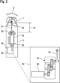
- a sectional side view of an embodiment of the personal care device of the preceding figures, illustrating a restoring device for restoring the working head towards a neutral swiveling position, wherein such restoring device includes a leaf spring and the adjustment actuator for adjusting the restoring characteristic is configured to vary the effective length of the leaf spring,
- Figure 4:
- an adjustment actuator similar to
figure 3 , including an electric motor and a gearing for displacing an adjustment element, wherein partial view a) shows front view of the entire gearing including the motor and the adjustment element driven thereby and partial view b) shows a side view of the adjustment element driven by the output gear of the gearing and a pair of end switches for detecting the position of the adjustment element, - Figure 5:
- a sectional side view of another embodiment of the personal care device of the
figures 1 and2 , illustrating the adjustment actuator for adjusting the swiveling range, - Figure 6:
- a sectional side view of the personal care device having a swiveling range limiter similar to
figure 5 , wherein the adjustment actuator includes a smart material actuation element in terms of a bimetal bar changing its shape when subject to heating and cooling, - Figure 7:
- a sectional side view of the personal care device of
figure 6 , wherein the bimetal bar of the smart material actuator is shown in a different configuration after having been subject to heating, - Figure 8:
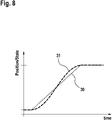
- a functional diagram showing the position/state of an actuation element versus time, wherein a linear transition and a non-linear transition between two states are illustrated, and
- Figure 9:
- a sectional side view of a personal care device having an adjustment actuator including a smart material in terms of a smart fluid changing its viscosity upon subject to an electric current through a coil and a magnetic field respectively, to adjust the swiveling resistance of the working head.
- As becomes apparent from the Figures, it is suggested to provide for an adjustment actuator which is configured and controlled to achieve a smooth transition between different settings of the treatment characteristics. More particularly, the adjustment actuator may be configured and controlled to adjust the treatment characteristic from a first setting to a second setting within a time period of not less than 0.1 seconds and not more than 1.5 seconds. Advantageously, the adjustment actuator may be configured and controlled to achieve transition between the two settings within a time period of not less than 0.15 seconds and not more than 0.5 seconds or a transition time period of not less than 0.15 seconds and not more than 0.25 seconds.
- To achieve the desired smooth transitions between different settings of the treatment characteristics, the adjustment actuator is operated with a limited change rate so the transition from one state such as "soft" to another one such as "hard" happens within a well-defined time duration. On the one hand, transition should not be too fast because immediate changes could disturb the user. On the other hand, the transition should be fast enough to get the setting of the treatment characteristic much with variations of the treatment region and/or variations of the way of using the personal care device such as changing from short strokes to long strokes.
- When the personal care device is moved along the body surface in a reciprocating way, the adjustment actuator may be configured and controlled to effect the transition from a first setting to a second setting of the treatment characteristics within one or two strokes.
- The adjustment actuator may be configured to allow operation at different speeds, wherein a control unit for controlling the adjustment actuator may be configured to vary the transition time spent for effecting the adjustment, i.e. transition from a first setting to a second setting depending on user habits and/or preferences and/or operational situations. For example, when changing from long stroke use to short stroke use, it may be advantageous to effect transition from, for example, a softer working head configuration to a harder working head configuration within a shorter transition time of, for example, 0.15 to 0.20 seconds, whereas, on the other hand, it may be advantageous to effect transition from the harder setting to the softer setting, when changing from short-stroke operation to long-stroke operation, within a longer transition time period of, for example, 0.20 seconds to 0.25 seconds.
- To make the transition smooth, but nevertheless quick, it may be advantageous to configure and/or control the adjustment actuator to provide for a non-constant transition speed and/or to operate at a non-constant speed over the transition time period, wherein, for example, the transition speed may be reduced at an initial phase and/or at an end phase of the transition, whereas transition speed may be increased at a medium phase of the transition.
- For the user, several advantages are related to well controlled change of the described states:
- The behaviour of the device appears less nervous compared to a device with an actuator that looks and feels like jumping.
- The velocity of the actuator may even be adapted to the behaviour of the specific user, as it may have been recorded by sensors and learned by an algorithm during a treatment. An example for such a quantity may be the amount of strokes per unit of time or the average velocity of the personal care device over the body surface.
- The characteristic of the device changes smoothly and the user does not feel the process of the change itself, but only the new device adjustment.
- If the movement of the adjustment actuator is related to a movement, in particular a contour adaption movement such as swivelling of the working head and/or an element thereof, a slow actuation avoids any sudden movement and as a result a non desirable mechanical impact onto the skin.
- Any unexpected shake of the handle during any sudden fast actuation can be avoided.
- An actuator with limited speed can be built up with lower power compared to a very fast actuator. Since volume and power of an engine are strongly correlated, the device, in particular its handle can be built smaller and with a more attractive design.
- Several advantages and simplifications also can be found for the actuator if a considerable time is allowed for a movement to a new position.
- It may need less driving power, e.g. at a given voltage less electrical current, because the actuator may deliver some mechanical energy during its movement. When the actuator has more time for its movement, the needed power is less for achieving the same total mechanical energy.
- A slower / smaller actuator can be cheaper than a fast, strong and big one
- A slower actuator leads to less force needed to accelerate the involved parts. This translates into less wear in the mechanics
- So as to allow for easy, but nevertheless precise control, the adjustment actuator may be under control of an electronic control unit and/or responsive to electronic control commands.
- For example, the adjustment actuator may include an electric motor which may displace an adjustment element such as a spring bearing of a spring element influencing stiffness of the movable working head and/or a range limiter, wherein a gearing may be provided between said electric motor and the adjustment element to transmit the drive motion of the electric motor to the adjustment element. Such electric motor, which may be combined with a gear box, allows for easy and precise control of the adjustment action and, at the same time, easy variation of the transition speed.
- In addition or in the alternative, the adjustment actuator also may include a smart material changing a material property to control the adjustment, when subject to a control signal and/or subject to predefined ambient conditions.
- For example, the adjustment actuator may include a smart fluid changing its viscosity when subject to a magnetic field and/or an electric field, wherein such smart fluid may cooperate with an adjustment element to change the displacement resistance thereof. Such adjustment actuator may be provided for varying the moving resistance depending on moving speed and/or may include a viscose type of friction device which may include a fluid pusher to push away a viscose fluid when moving. To adjust the moving resistance, a smart viscose fluid may be used which is configured to change its viscosity when subject to a magnetic field and/or electric current to allow for quick changes of viscosity to allow for adjustments during one round of personal care treatment. Such viscose friction device may provide for a moving resistance increasing with moving speed. More particularly, such viscose friction device may include an adjustable damper configured to provide varying damping forces.
- In addition or in the alternative, the adjustment actuator may include a smart metal such as a bimetal changing its shape when subject to heating and/or cooling.
- According to another aspect, at least one adjustment actuator may be provided for varying a breaking resistance counteracting and/or braking movement of the working head and/or the working head element irrespective of the direction thereof. Contrary to biasing devices such as preloading springs urging the working head towards a certain position, such braking resistance counteracts and/or brakes the working head and/or working head element moving in either direction. In other words, the direction of the braking force changes with the direction of the movement of the working head and/or working head element to always counteract such movements.
- In addition or in the alternative, the adjustment device may include a restoring for urging the working head and/or the working head element towards a desired neutral position, wherein such restoring device may include at least one spring element such as a leaf spring connected to the working head and/or the working head element, wherein the adjustment actuator may be configured to change the effective length of such leaf spring.
- As can be seen from
figure 1 , the personal care device 20 includes anelongated handle 2 to be gripped by the fingers of a user to move the personal care device 20 along a body surface to be treated. Saidhandle 2 may form a housing in which functional and/or structural parts of the personal care device 20 may be accommodated, for example an energy storage such as a battery, a drive motor and/or a control unit for controlling the function such as a microprocessor with a program storage connected thereto. - A working
head 1 supported on saidhandle 2 includes one or more working head elements 7 for performing the care treatment. In case of a shaver which is illustrated in the figures, said working head element 7 may include hair cutting elements such as shear foil cartridges and/or a rake-like trimmer, cf.figure 2 . - The working head element 7 may define a
skin contact surface 17 of the workinghead 1, wherein saidskin contact surface 17 may extend substantially perpendicular to a longitudinal axis of thehandle 2 or inclined thereto, depending on the rotatory position of the workinghead 1. For example, theskin contact surface 17 may be formed by a distal end side of the workinghead 1. - As illustrated by
figures 1 and2 , the workinghead 1 may be supported on thehandle 2, by means of asuspension 18, in a movable manner so that the workinghead 1 may be rotated and/or linearly displaced relative to thehandle 2. For example, thesuspension 18 may allow for swiveling 3 of the workinghead 1 about a swivel axis 4, cf.figure 2 , and/or tilting 5 of the workinghead 1 about atilt axis 6. Said swivel andtilt axes 4 and 6 may extend substantially perpendicular to each other and/or substantially parallel to the aforementionedskin contact surface 17, cf.figure 2 . - In addition or in the alternative to such rotatory movability, the working
head 1 also may be linearly displaced relative to thehandle 2, for example along a displacement axis substantially parallel to the longitudinal axis of thehandle 2 so that the workinghead 1, as a whole, may dive or float when theskin contact surface 17 is pressed against the body surface. - In addition or in the alternative to the movability of the working
head 1 as a whole, one or more working heads 7 such as the aforementioned shear foil cartridges, may be movably supported relative to a workinghead base 10 by means of asuspension 19. The workinghead base 10 may form a frame-like structure which may swivel and/or tilt relative to thehandle 2 in the aforementioned manner so that the additional movability of the working head element 7 may be superposed to the movability of the workinghead base 10. - For example, the working head elements 7 may be linearly displaced along a displacement axis 8 which may extend substantially perpendicular to the
skin contact surface 17 so that the working head element 7 may dive or float when subject to skin contact pressure. In addition or in the alternative to such linear diving, thesuspension 19 of the working head element 7 also may allow for rotatory movements of the working head elements 7 relative to the workinghead base 10 to allow for adaption of the working head element 7 to the skin contour. In particular, the working head element 7 may tilt along a tilt axis parallel to tilt axis6of working head 1. - The adaptive movements of the working
head 1 and/or the working head element 7 to the skin contour may be controlled by anadaption controller 24 which may include one or more mechanisms and/or actuators and/or mechanical controllers to influence one or more of the aforementioned movements. - For example, as shown by
figure 3 , theadaption controller 24 may include a restoringdevice 25 applying a restoring force and/or torque onto the workinghead 1 to urge the workinghead 1 towards a neutral or starting position which may be an intermediate position from which the workinghead 1 may move into opposite directions. Alternatively, the neutral or start position may be an end position at the swivel or tilt range. For example, the restoringdevice 25 may be configured to urge the workinghead 1 into a neutral swivel position about swivel axis 4. - Said restoring
device 25 may include aleaf spring 31 connected or rigidly fixed to the workinghead base 10 in a way such thatswivel 3 of the workinghead 1 causes theleaf spring 31 to pivot and thus, bend. As can be seen fromfigure 5 ,leaf spring 31 is also connected to thehandle 2 or a structural element fixed to saidhandle 2, by means of aspring bearing 32 which limits rotatory movements of theleaf spring 31 due to swiveling of the workinghead 1. - So as to adjust the restoring force and/or restoring torque of the
leaf spring 31, theeffective length 33 of theleaf spring 31 may be adjusted, wherein, for example, the aforementioned spring bearing 32 may be displaced in a direction substantially parallel to the longitudinal axis of theleaf spring 31. For example, thespring bearing 32 may be displaced in a direction parallel to the longitudinal axis of thehandle 2, cf.figure 5 , to change theeffective length 33 ofleaf spring 31. - Displacement of the
spring bearing 32 may be effected by means of anadjustment actuator 35 which can be controlled by the aforementioned control unit. For example, saidactuator 35 may include amotor 36 such as an electric motor which is connected to the displaceable spring bearing 32 via a drive train or connector ortransmitter 34 transmitting the drive movement of themotor 36 to thespring bearing 32. Saidmotor 36 may be a DC motor. - For example, a
gearing 37 may be provided between a drive shaft ofmotor 36 andtransmitter 34 so as to transform, for example, a rotatory drive shaft movement into a substantially linear displacement of thespring bearing 32. - Advantageously, the change rate of the active element in terms of said displaceable spring bearing 32 can be understood as a velocity of some actuator mechanics. It may move from one position to another one within a transition time duration that is not perceived as a sudden disturbing movement.
- As can be seen from
Fig. 4 , anelectronic control unit 39, which may include a microprocessor and a storage unit for storing a control software, may drives saidmotor 36 via suitable power electronics. - The combination of controller and suitable electronics may be built up in a way that it can drive the
motor 36 in both directions and with variable speed. Many solutions for such a set-up exist, such as the use of a so-called H-bridge drivers and of pulse width modulated motor voltage. - The motor current may be measured by the controller. This can be done via a shunt resistor, i.e. a resistor that the motor current flows through and the measurement of the voltage across this resistor.
- The
gearing 37 may be built up with cogwheels. The gearing could be built up differently as well, e.g. it may include a worm gear, cf.figure 5 , or a gearing of the type harmonic drive. By at least one of those gearings, it may be possible to prevent movement without actuation which allows self-blocking of the gearing. - The
last stage 38 of the gearing may drive a transmitter such as alever 34 that is attached to some connector such as thespring bearing 32 or more generally, an element that is able to adjust a property of the head such as the range limiter shown inFig. 5 . The element also could be a spring, attached to some point at the pivotable head and adjusting its stiffness against rotations. - Different states and positions of the
lever 34 correspond to different values of the head stiffness. The positions of thelever 34 include 2 end positions, a lower position and an upper position, and may include further positions in-between. - Advantageously, the adjustment actuator may be stopped and held at various positions including at least one intermediate position between two end positions to allow for fine adjustment. More particularly, the adjustment actuator may be continuously and/or step-by-step operated and stopped at various desired positions to provide for continuous and/or step-by-step adaption of the treatment characteristic.
- The lower position may be used for adjusting the head to low stiffness and the upper position may be used for adjusting the head to high stiffness, cf.
Fig. 3 . - A detection device may be provided for detecting the end positions of the
lever 34, wherein said detection device may include one or more of the following: - ∘ end switches 115, 116 at the lower and the upper position.
- ∘ a lower and an upper mechanical limit for the
lever 34, wherein, when the lever reaches such a limit, a force may build up which then leads to an increased torque and increased current in themotor 36. The increased current can be measured via the previously mentioned shunt resistor. - ∘ A position sensor for detecting the end positions and/or intermediate positions.
- For driving the
lever 34 to one of the end positions, the controller may drive the motor in the corresponding direction until the end position is detected. - For driving the
lever 34 from an end position to an intermediate position, the controller drives the motor for a defined amount of time into the desired direction. The defined amount of time is derived from the needed movement distance and the velocity of the lever. This velocity can be assumed as constant or, for more accuracy, it can be estimated via the motor current. Higher current corresponds to lower motor velocity. - For even more improving the smoothness of the transition between the states, the controller increases the speed of the
motor 36 with a defined rate at the beginning of the motion and also slows down the motor with a defined rate at the end. Any sudden starting or stopping of themotor 36 is avoided in this way. - While a transition with constant speed corresponds to the
curve 30 offigure 8 , an even smoother transition with defined rate of speed increase corresponds tocurve 31, cf.fig. 8 , wherein the slope of thecurve 31 changes gradually rather than in steps. For determining the position of thelever 34 in intermediate positions, the non-constant, but variable speed may be taken into account. - As shown by
Fig. 3 , the restoringdevice 35 may be configured such that theaforementioned leaf spring 31 is undeflected and/or straight when the workinghead 1 is in its neutral position. Thus, no torque and/or restoring force is applied to workinghead 1 when the later is in its neutral position. In other words, when starting displacement of the workinghead 1 out of its neutral position, substantially no torque and/or force is necessary so swiveling 3 may start at substantially zero resistance at the neutral position. - Depending on the configuration of the restoring
device 25, different restoring characteristics may be provided. For example, the swiveling and/or tilting torque may increase with increasing swivel and/or tilt angles in a non-linear way. The larger the swivel or tilt angle gets, the steeper the torque increase may become. When theeffective length 33 is reduced, the rotation stiffness increases, whereas increasing theeffective length 33 leads to a reduced rotation stiffness. The torque characteristic also may be a linear one, wherein the resistive and/or restoring torque may linearly increase with an increasing swivel or tilt angle. Again, swivel or tilt stiffness may be adjusted also in case of a linear characteristic. - Also for linear displacements of the working
head 1 and/or the working head element 7, such as the diving movements 8 as shown byfigure 2 , different force characteristics may be provided. For example, a restoring device including a leaf spring similar as the restoringdevice 25 may be employed, wherein for example the leaf spring, with its longitudinal axis, may be arranged transverse to the diving axis 8 to be deflected when the working head element dives. Again, adjusting diving stiffness may be achieved by increasing and/or decreasing the effective length of such leaf spring. In addition or in the alternative, other restoring devices including other types of springs such as a compression spring may be used to influence the diving characteristics, wherein for example the spring bearing may be displaced along the axis of compression. - As shown by
figures 5 to 7 , contour adaption movements of the workinghead 1 also may be controlled by a displacement range limiter 58 which may limit the available maximum rotatory and/or linear displacement. - For example, as shown by
figure 5 , the displacement range limiter 58 may limit themaximum swiveling 3 of workinghead 1. - In this embodiment, an
actuator 50..54 is used to push a wedge 55 into agap 56 at the bottom of the shavinghead 1. Depending on the extent how far the actuator moves the wedge into the gap along thedirection 57, the swivel range is more or less limited. In the lower position of the wedge 55, the swivel rotation has a wide range. With upward moving wedge, the range becomes smaller until the swivel rotation is completely blocked when the wedge is moved to its upper mechanical limit. The head is then forced into a predefined position. In detail, the adjustment actuator may work as follows: amotor 50 such as a DC-motor may turn agear 51, which drives asecond gear 52. Thisgear 52 contains aninternal thread 53 and is placed on a threadedrod 54. - The threaded rod is moved up and down, as soon as the
motor 50 turns. In summary, the minimum- 41 and maximum- 42 angles of the head swiveling can be adjusted with the help of themotor 50. Advantageously, themotor 50 may be stopped and held at intermediate positions to define intermediate rotatory displacement ranges smaller than the maximum range and larger than the minimum range (which may be zero or larger than zero). - As can be seen from
Fig. 6 and 7 , the adjustment actuator may include a smart material such as a bimetal strip or bar for effecting the adjustment movement of the adjustment element. - Basically, different types of smart materials may be used for implementing the adjustment actuator, such as materials changing their properties under the influence of ambient conditions, such as temperature, electric field, magnetic field, light and/or chemistry.
- For example, a setup with a material that changes shape with temperature is described.
- A
piece 120 of material that bends differently, depending on the temperature may be chosen. This can be a piece of bimetal. - As shown by
Fig. 6 ,such piece 120 may be a rod or bar and/or may be rigidly supported at one end to allow for bending and/or deflection and thus, movement of the other end. As shown byFig. 6 , the smart material, in a first configuration, may bend in a way that it holds thelever 34 in its lower position. - Some heating means such as an
electrical resistor 121 may be activated to apply heating to thebimetal piece 120, wherein an electrical current may be forced to flow through the resistor. By adjusting the current via thecontrol unit 39, the temperature of thepiece 120 of smart materials is adjusted to a defined value. As a result, the bending changes to a shape that is related to the temperature. - A maximum current and maximum temperature moves the
lever 34 to the upper position (Fig.7 ) and smaller amounts of heating move it to intermediate positions. - For the way to the upper position, the limited velocity is obtained by the heat capacitance of the piece of smart material and the power that is used to heat it up. So, it just needs time to get heated up. For the way to the lower position, the limited velocity is obtained by the combination of the heat capacitance and the cooling that the piece of smart material experiences in its surrounding.
- Another example of a set-up with a smart material is shown by
Fig. 9 . In this case, the difference between different states of the mechanism is not a different position, but a difference in mechanical resistance or stiffness. Mechanical resistance may be understood as a quantity that relates the force that is needed to move a mechanical part with the velocity that is achieved by applying this force. It can also be understood as the ratio of such a force and such a velocity. - More particularly, as shown by
Fig. 9 , a viscose type of friction device 100 may include a fluid pusher for pushing a viscose fluid away when the workinghead 1 and/or working head element 7 moves to adapt to the body surface contour. To adjust the resistance of the fluid pusher in dependency of speed, a smart viscose fluid may be used which is configured to change its viscosity when subject to a magnetic field and/or subject to electric current. - More particularly, as shown by
figure 9 , a connectingrod 101 moves theelement 102 up and down synchronously with the swivel rotation of the head. Thiselement 102 acts as an inner damper element. This inner damper element is located inside the outer dampingelement 103. The space between inner and outer damping is filled with amagnetic liquid 104. The magnetic liquid is located between the poles of an electromagnet consisting of aniron core 105 and one ormore coils 106. The viscosity of themagnetic liquid 104 is modified with the help of an electrical current through the coil(s) 106. - Depending on the current, the coil(s) generate a magnetic field in the volume of the
magnetic liquid 104. The higher the magnetic field, the higher is the viscosity of the magnetic liquid. A higher level of damping is then perceived by the user when the head is swiveled. If the current through thecoil 106 is lowered, the characteristics is modified towards thecurve 31. In summary, the current through thecoil 106 controls the torque, needed to swivel thehead 1 with a specific rotation speed. - The strength of the field changing viscosity may be controlled by an
electric control unit 107. - As a consequence, the mechanical resistance of the lever against vertical movements and as a second consequence also the resistance of the
head 1 againstrotations 3 is adjusted. - To achieve the before mentioned smooth transition between different states, the electrical field is controlled in such a way that it changes with a defined rate.
- In summary, there is a relation between the rotation speed of the
head 1 and the torque that is applied against this rotation. Theelectronic control 107 can adjust this relation in a way that the head can pivot more or less easily and the transition is not perceived as an unexpected sudden resistance.
Claims (19)
- Personal care device, in particular hair removal device such as an electric shaver, comprising an elongated handle (2) for manually moving the personal care device along a body surface, a working head (1) attached to said handle (2), said working head (1) having at least one working head element (7) for effecting a personal care treatment to said body surface, wherein an adjustment device (26) including at least one adjustment actuator is provided for adjusting at least one treatment characteristic, characterized in that said adjustment actuator (35; 50; 80, 81; 105, 106) is configured and controlled to adjust said at least one treatment characteristic from a first setting to a second setting within a transition time period of not less than 0.1 seconds and not more than 1.5 seconds.
- Personal care device, in particular hair removal device such as an electric shaver, comprising an elongated handle (2) for manually moving the personal care device along a body surface, a working head (1) attached to said handle (2), said working head (1) having at least one working head element (7) for effecting a personal care treatment to said body surface, wherein an adjustment device (26) including at least one adjustment actuator is provided for adjusting at least one treatment characteristic.
- Personal care device according to the preceding claim, wherein said transition time period is not less than 0.15 and not more than 0.50 seconds or not less than 0.15 seconds and not more than 0.25 seconds.
- Personal care device according to anyone of the preceding claims, wherein said adjustment actuator (35; 50; 80, 81; 105, 106) is configured to vary the transition time period spent for effecting the adjustment of the treatment characteristic in response to a user preference signal and/or in response to a detected change of the operational situation.
- Personal care device according to anyone of the preceding claims, wherein the at least one adjustment actuator (35; 60; 80, 81; 105, 106) is configured and controlled to adjust the at least one treatment characteristic at a transition speed which is non-constant over the transition time period, wherein transition speed is reduced at an initial phase and/or at an end phase of the transitional time period and/or increased at a medium phase of the transitional time period.
- Personal care device according to anyone of the preceding claims, wherein said at least one adjustment actuator is under control of an electronic control unit configured to control the response time and/or the speed of said adjustment actuator to effect the adjustment of the at least one treatment characteristic to be within the desired adjustment time period.
- Personal care device according to anyone of the preceding claims, wherein said at least one adjustment actuator is configured and controlled to be stopped and held at at least one intermediate position between two end positions to adjust the treatment characteristic to at least one intermediate setting in addition to first and second settings corresponding to the end positions.
- Personal care device according to anyone of the preceding claims, wherein said at least one adjustment actuator includes an electric motor (36) for displacing a displaceable adjustment element (34) from a first position to a second position within said transition time period.
- Personal care device according to the preceding claim, wherein said electric motor (36) is connected to said adjustment element (34) via a gearing, in particular a cog wheel gearing.
- Personal care device according to one of the two preceding claims, wherein said electric motor (36) is controlled to increase motor speed with a predefined rate at an initial phase and/or slow down motor speed at a predefined rate at an end phase so motor speed is reduced, in comparison to a medium phase of operation, at said initial phase and/or at said end phase.
- Personal care device according to anyone of the preceding claims, wherein said at least one adjustment actuator (80, 81; 105, 106) includes a smart material actuation element changing a material property to control the adjustment, when subject to a control signal and/or a predefined ambient condition.
- Personal care device according to the preceding claim, wherein said smart material adjustment element includes a bimetal actuation element (120) changing its shape upon subject to heating and/or cooling, wherein said bimetal actuation element (120) is connected to an adjustment element via a transmitter (34) so that changes in shape of the bimetal actuation element are transformed into displacement of the adjustment element.
- Personal care device according to one of the two preceding claims, wherein said smart material adjustment element includes a smart fluid changing its viscosity when subject to a magnetic field and/or a field of electricity.
- Personal care device according to the preceeding claim, wherein said adjustment actuator (105, 106) includes a fluid pusher connected to the working head (1) and/or the working head element (7) for pushing away the smart viscose fluid when the working head (1) and/or the working head element (7) is moving, wherein said viscose fluid is a smart viscose fluid changing its viscosity depending on a magnetic field applied thereto, wherein the adjustment device (105, 106) includes a controller for changing said magnetic field.
- Personal care device according to anyone of the preceding claims, wherein said treatment characteristic is contour adaptivity of the working head (1) and/or of a working head element (7), wherein said at least one adjustment actuator (35; 50; 80, 81, 82; 105, 106) is configured to adjust said contour adaptivity.
- Personal care device according to the preceding claim, wherein said adjustment device (26) includes at least one actuator (35; 50; 80, 81, 82; 105, 106) for adjusting at least one of the following characteristics:moving resistance of the working head (1) and/or of the working head element (7) depending on moving speed of the working head (1) and/or the working head element (7), restoring force/torque urging the working head (1) and/or the working head element (7) towards a neutral position depending on rotatory and/or linear displacement and/or moving speed of the working head (1) and/or of the working head element (7),braking force/torque for braking movements of the working head (1) and/or of the working head element (7) into each of opposite directions,rotatory and/or linear displacement range of said working head (1) and/or of said working head element (7) out of a neutral position.
- Personal care device according to one of the preceding claims, wherein said adjustment actuator (35) for adjusting the restoring force/torque and/or the shape of the graph defining restoring force/torque over linear and/or rotatory displacement of the working head (1) and/or the working head element (7) is configured to adjust the restoring force/torque of a restoring device (25), wherein said restoring device (25) includes a leaf spring (31) connected to the working head (1) and/or the working head element (7) in a way to be deflected by contour adaption movements of the working head (1) and/or the working head element (7), wherein the adjustment actuator (35) is configured to adjust an effective length (33) of said leaf spring (31) by means of displacing a spring bearing (32).
- Personal care device according to one of the preceding claims, wherein said adjustment device (26) includes a displacement range limiter (58) for limiting a maximum available rotatory and/or linear displacement of said working head (1) and/or said working head element (7), wherein said displacement range limiter (58) is adjustable by an adjustment actuator (50) to change the available displacement range.
- Personal care device according to the preceding claim, wherein said range limiter (58) includes a pair of engagement elements, one of which is wedge-shaped and one of which is roof-shaped, wherein at least one of said engagement elements is movably supported to be moved towards and away from the other engagement element such that wedge-shaped contour may enter into the roof-shaped contour, wherein the adjustment actuator (50) is configured to hold the engagement elements at varying distances from each other defining varying displacement ranges.
Priority Applications (4)
| Application Number | Priority Date | Filing Date | Title |
|---|---|---|---|
| EP21188505.8A EP4124422B1 (en) | 2021-07-29 | 2021-07-29 | Personal care device |
| US17/875,489 US12570015B2 (en) | 2021-07-29 | 2022-07-28 | Personal care device |
| CN202210903024.2A CN115674285A (en) | 2021-07-29 | 2022-07-29 | personal care device |
| JP2022121373A JP7617062B2 (en) | 2021-07-29 | 2022-07-29 | Personal Care Devices |
Applications Claiming Priority (1)
| Application Number | Priority Date | Filing Date | Title |
|---|---|---|---|
| EP21188505.8A EP4124422B1 (en) | 2021-07-29 | 2021-07-29 | Personal care device |
Publications (2)
| Publication Number | Publication Date |
|---|---|
| EP4124422A1 true EP4124422A1 (en) | 2023-02-01 |
| EP4124422B1 EP4124422B1 (en) | 2025-12-10 |
Family
ID=77126671
Family Applications (1)
| Application Number | Title | Priority Date | Filing Date |
|---|---|---|---|
| EP21188505.8A Active EP4124422B1 (en) | 2021-07-29 | 2021-07-29 | Personal care device |
Country Status (4)
| Country | Link |
|---|---|
| US (1) | US12570015B2 (en) |
| EP (1) | EP4124422B1 (en) |
| JP (1) | JP7617062B2 (en) |
| CN (1) | CN115674285A (en) |
Families Citing this family (3)
| Publication number | Priority date | Publication date | Assignee | Title |
|---|---|---|---|---|
| CN221677275U (en) * | 2021-05-14 | 2024-09-10 | 光达家电用品公司 | Hair clipper device |
| EP4112251B1 (en) * | 2021-06-30 | 2026-04-08 | Braun GmbH | Personal care device |
| EP4484084B1 (en) * | 2023-06-29 | 2026-01-21 | Braun GmbH | Hair cutter |
Citations (12)
| Publication number | Priority date | Publication date | Assignee | Title |
|---|---|---|---|---|
| DE19601780C1 (en) * | 1996-01-19 | 1997-06-26 | Braun Ag | Electric shaver with indicator of maximum deflection of cutting head |
| US20080163495A1 (en) * | 2005-07-07 | 2008-07-10 | Faco S. A. | Hair Clipper With Motorised Cutting Guide |
| EP2208588A1 (en) * | 2009-01-15 | 2010-07-21 | Panasonic Electric Works Co., Ltd. | Electric shaver |
| WO2013140309A1 (en) * | 2012-03-22 | 2013-09-26 | Koninklijke Philips N.V. | Shaver having adaptive surface |
| US20150246454A1 (en) * | 2014-02-28 | 2015-09-03 | Medline Industries, Inc. | Method and Apparatus for a Clipper |
| WO2015135682A1 (en) * | 2014-03-14 | 2015-09-17 | Koninklijke Philips N.V. | Electric shaver |
| WO2016046142A1 (en) * | 2014-09-26 | 2016-03-31 | Koninklijke Philips N.V. | Shaving device for skin hairs |
| WO2017220352A1 (en) * | 2016-06-20 | 2017-12-28 | Koninklijke Philips N.V. | Friction control device and method |
| WO2018069265A1 (en) | 2016-10-14 | 2018-04-19 | Koninklijke Philips N.V. | Cutting length adjustment mechanism, adjustment drive and hair cutting appliance |
| EP3546149A1 (en) * | 2018-03-27 | 2019-10-02 | Braun GmbH | Hair removal device |
| EP3546153A1 (en) | 2018-03-27 | 2019-10-02 | Braun GmbH | Personal care device |
| EP3546152B1 (en) | 2018-03-27 | 2021-04-21 | Braun GmbH | Hair removal apparatus |
Family Cites Families (31)
| Publication number | Priority date | Publication date | Assignee | Title |
|---|---|---|---|---|
| DE3726354A1 (en) | 1987-08-07 | 1989-02-16 | Braun Ag | ELECTRIC SHAVER WITH CUTTER HEAD CONTROL |
| ES2122594T3 (en) | 1994-06-01 | 1998-12-16 | Koninkl Philips Electronics Nv | SHAVING DEVICE WITH ELECTRICALLY ADJUSTABLE CUTTING UNIT. |
| DE19531012C1 (en) | 1995-08-22 | 1996-10-17 | Braun Ag | Electric shaver |
| JP4772205B2 (en) | 2001-04-18 | 2011-09-14 | 九州日立マクセル株式会社 | Electric razor |
| DE60206070T2 (en) * | 2001-11-15 | 2006-06-14 | Matsushita Electric Works Ltd | DRY RAZOR WITH SWIVEL HEAD |
| JP2004316797A (en) | 2003-04-17 | 2004-11-11 | Bando Chem Ind Ltd | Magneto-rheological fluid damper |
| JP4552646B2 (en) * | 2004-12-16 | 2010-09-29 | パナソニック電工株式会社 | Hair removal equipment |
| DE102006004675A1 (en) | 2006-02-02 | 2007-08-09 | Braun Gmbh | Electric razor |
| US20080034591A1 (en) * | 2006-08-08 | 2008-02-14 | Kam Fai Fung | Shaver with swivel head |
| JP2008224001A (en) | 2007-03-15 | 2008-09-25 | Honda Motor Co Ltd | Variable damping force damper |
| JP5009940B2 (en) | 2009-01-15 | 2012-08-29 | パナソニック株式会社 | Electric shaver |
| JP2010227224A (en) | 2009-03-26 | 2010-10-14 | Panasonic Electric Works Co Ltd | Electric razor |
| JP5401280B2 (en) | 2009-11-27 | 2014-01-29 | 株式会社沖データ | Image forming apparatus |
| JP2011211606A (en) | 2010-03-30 | 2011-10-20 | Hitachi Computer Peripherals Co Ltd | Imaging apparatus |
| US8745883B2 (en) | 2010-09-29 | 2014-06-10 | The Gillette Company | Razor handle with a rotatable portion |
| ES2601806T3 (en) | 2011-04-05 | 2017-02-16 | The Gillette Company Llc | Razor handle with rotatable part |
| ES2469390T3 (en) | 2011-04-15 | 2014-06-18 | The Gillette Company | Manual device that has a rotation axis |
| EP2550935B1 (en) * | 2011-07-25 | 2014-04-23 | Braun GmbH | Personal care device |
| US9925676B2 (en) * | 2011-12-21 | 2018-03-27 | Matthew W. Krenik | Automated hair cutting system and method of operation thereof |
| JP2014001643A (en) | 2012-06-15 | 2014-01-09 | Ebara Corp | Vacuum pump |
| JP2014067157A (en) | 2012-09-25 | 2014-04-17 | Nec Access Technica Ltd | Radio communication terminal |
| JP6157856B2 (en) * | 2013-01-10 | 2017-07-05 | カルソニックカンセイ株式会社 | Heat sensing device |
| JP6395303B2 (en) | 2014-10-15 | 2018-09-26 | マクセルホールディングス株式会社 | Electric razor |
| EP3262971B1 (en) * | 2016-06-30 | 2021-01-06 | Braun GmbH | Epilation device measuring contact force and comprising a feedback unit |
| EP3300843B1 (en) | 2016-09-28 | 2020-04-15 | Braun GmbH | Electric shaver |
| JP6667162B2 (en) * | 2017-02-24 | 2020-03-18 | パナソニックIpマネジメント株式会社 | Portable hairdressing and beauty equipment |
| EP3546151B1 (en) * | 2018-03-27 | 2025-04-30 | Braun GmbH | BODY CARE DEVICE |
| EP3546148B1 (en) * | 2018-03-27 | 2022-01-12 | Braun GmbH | Personal care device |
| EP3546150B1 (en) * | 2018-03-27 | 2021-10-27 | Braun GmbH | Personal care device |
| EP3738730A1 (en) | 2019-05-14 | 2020-11-18 | Koninklijke Philips N.V. | Shaving apparatus with drive for setting an operational parameter |
| JP7754173B2 (en) | 2021-07-27 | 2025-10-15 | 株式会社村田製作所 | Handles, shavers, hair dryers, curling irons, hair brushes, and eyelash curlers |
-
2021
- 2021-07-29 EP EP21188505.8A patent/EP4124422B1/en active Active
-
2022
- 2022-07-28 US US17/875,489 patent/US12570015B2/en active Active
- 2022-07-29 JP JP2022121373A patent/JP7617062B2/en active Active
- 2022-07-29 CN CN202210903024.2A patent/CN115674285A/en active Pending
Patent Citations (12)
| Publication number | Priority date | Publication date | Assignee | Title |
|---|---|---|---|---|
| DE19601780C1 (en) * | 1996-01-19 | 1997-06-26 | Braun Ag | Electric shaver with indicator of maximum deflection of cutting head |
| US20080163495A1 (en) * | 2005-07-07 | 2008-07-10 | Faco S. A. | Hair Clipper With Motorised Cutting Guide |
| EP2208588A1 (en) * | 2009-01-15 | 2010-07-21 | Panasonic Electric Works Co., Ltd. | Electric shaver |
| WO2013140309A1 (en) * | 2012-03-22 | 2013-09-26 | Koninklijke Philips N.V. | Shaver having adaptive surface |
| US20150246454A1 (en) * | 2014-02-28 | 2015-09-03 | Medline Industries, Inc. | Method and Apparatus for a Clipper |
| WO2015135682A1 (en) * | 2014-03-14 | 2015-09-17 | Koninklijke Philips N.V. | Electric shaver |
| WO2016046142A1 (en) * | 2014-09-26 | 2016-03-31 | Koninklijke Philips N.V. | Shaving device for skin hairs |
| WO2017220352A1 (en) * | 2016-06-20 | 2017-12-28 | Koninklijke Philips N.V. | Friction control device and method |
| WO2018069265A1 (en) | 2016-10-14 | 2018-04-19 | Koninklijke Philips N.V. | Cutting length adjustment mechanism, adjustment drive and hair cutting appliance |
| EP3546149A1 (en) * | 2018-03-27 | 2019-10-02 | Braun GmbH | Hair removal device |
| EP3546153A1 (en) | 2018-03-27 | 2019-10-02 | Braun GmbH | Personal care device |
| EP3546152B1 (en) | 2018-03-27 | 2021-04-21 | Braun GmbH | Hair removal apparatus |
Also Published As
| Publication number | Publication date |
|---|---|
| US20230031671A1 (en) | 2023-02-02 |
| JP7617062B2 (en) | 2025-01-17 |
| CN115674285A (en) | 2023-02-03 |
| EP4124422B1 (en) | 2025-12-10 |
| US12570015B2 (en) | 2026-03-10 |
| JP2023021080A (en) | 2023-02-09 |
Similar Documents
| Publication | Publication Date | Title |
|---|---|---|
| US12570015B2 (en) | Personal care device | |
| JP7405512B2 (en) | personal care equipment | |
| JP7413313B2 (en) | personal care devices | |
| CN110303532B (en) | Personal care device | |
| US20230033691A1 (en) | Personal care device | |
| CN110303527B (en) | Hair removing device | |
| EP3546153B2 (en) | Personal care device | |
| EP3546152B1 (en) | Hair removal apparatus | |
| US8615886B1 (en) | Shaving system with energy imparting device | |
| CN1890065B (en) | Shaving head with skin stretching member | |
| US20090005715A1 (en) | Massage machine | |
| JP2021524357A (en) | Hair cutting equipment | |
| JP2007532223A (en) | Personal care device having means for the treatment of a body part for supplying an additive to the body part to be treated | |
| JP2007244855A (en) | Massage machine | |
| JP2026500819A (en) | Personal Care Device with Force Sensor |
Legal Events
| Date | Code | Title | Description |
|---|---|---|---|
| PUAI | Public reference made under article 153(3) epc to a published international application that has entered the european phase |
Free format text: ORIGINAL CODE: 0009012 |
|
| STAA | Information on the status of an ep patent application or granted ep patent |
Free format text: STATUS: THE APPLICATION HAS BEEN PUBLISHED |
|
| AK | Designated contracting states |
Kind code of ref document: A1 Designated state(s): AL AT BE BG CH CY CZ DE DK EE ES FI FR GB GR HR HU IE IS IT LI LT LU LV MC MK MT NL NO PL PT RO RS SE SI SK SM TR |
|
| P01 | Opt-out of the competence of the unified patent court (upc) registered |
Effective date: 20230430 |
|
| STAA | Information on the status of an ep patent application or granted ep patent |
Free format text: STATUS: REQUEST FOR EXAMINATION WAS MADE |
|
| 17P | Request for examination filed |
Effective date: 20230727 |
|
| RBV | Designated contracting states (corrected) |
Designated state(s): AL AT BE BG CH CY CZ DE DK EE ES FI FR GB GR HR HU IE IS IT LI LT LU LV MC MK MT NL NO PL PT RO RS SE SI SK SM TR |
|
| STAA | Information on the status of an ep patent application or granted ep patent |
Free format text: STATUS: EXAMINATION IS IN PROGRESS |
|
| 17Q | First examination report despatched |
Effective date: 20240926 |
|
| GRAP | Despatch of communication of intention to grant a patent |
Free format text: ORIGINAL CODE: EPIDOSNIGR1 |
|
| STAA | Information on the status of an ep patent application or granted ep patent |
Free format text: STATUS: GRANT OF PATENT IS INTENDED |
|
| INTG | Intention to grant announced |
Effective date: 20250711 |
|
| GRAS | Grant fee paid |
Free format text: ORIGINAL CODE: EPIDOSNIGR3 |
|
| GRAA | (expected) grant |
Free format text: ORIGINAL CODE: 0009210 |
|
| STAA | Information on the status of an ep patent application or granted ep patent |
Free format text: STATUS: THE PATENT HAS BEEN GRANTED |
|
| AK | Designated contracting states |
Kind code of ref document: B1 Designated state(s): AL AT BE BG CH CY CZ DE DK EE ES FI FR GB GR HR HU IE IS IT LI LT LU LV MC MK MT NL NO PL PT RO RS SE SI SK SM TR |
|
| REG | Reference to a national code |
Ref country code: CH Ref legal event code: F10 Free format text: ST27 STATUS EVENT CODE: U-0-0-F10-F00 (AS PROVIDED BY THE NATIONAL OFFICE) Effective date: 20251210 Ref country code: GB Ref legal event code: FG4D |
|
| REG | Reference to a national code |
Ref country code: DE Ref legal event code: R096 Ref document number: 602021043991 Country of ref document: DE Ref country code: IE Ref legal event code: FG4D |
|
| REG | Reference to a national code |
Ref country code: NL Ref legal event code: FP |
|
| PG25 | Lapsed in a contracting state [announced via postgrant information from national office to epo] |
Ref country code: ES Free format text: LAPSE BECAUSE OF FAILURE TO SUBMIT A TRANSLATION OF THE DESCRIPTION OR TO PAY THE FEE WITHIN THE PRESCRIBED TIME-LIMIT Effective date: 20251210 |
|
| REG | Reference to a national code |
Ref country code: LT Ref legal event code: MG9D |
|
| PG25 | Lapsed in a contracting state [announced via postgrant information from national office to epo] |
Ref country code: NO Free format text: LAPSE BECAUSE OF FAILURE TO SUBMIT A TRANSLATION OF THE DESCRIPTION OR TO PAY THE FEE WITHIN THE PRESCRIBED TIME-LIMIT Effective date: 20260310 |
|
| PG25 | Lapsed in a contracting state [announced via postgrant information from national office to epo] |
Ref country code: FI Free format text: LAPSE BECAUSE OF FAILURE TO SUBMIT A TRANSLATION OF THE DESCRIPTION OR TO PAY THE FEE WITHIN THE PRESCRIBED TIME-LIMIT Effective date: 20251210 Ref country code: HR Free format text: LAPSE BECAUSE OF FAILURE TO SUBMIT A TRANSLATION OF THE DESCRIPTION OR TO PAY THE FEE WITHIN THE PRESCRIBED TIME-LIMIT Effective date: 20251210 |
|
| PG25 | Lapsed in a contracting state [announced via postgrant information from national office to epo] |
Ref country code: RS Free format text: LAPSE BECAUSE OF FAILURE TO SUBMIT A TRANSLATION OF THE DESCRIPTION OR TO PAY THE FEE WITHIN THE PRESCRIBED TIME-LIMIT Effective date: 20260310 |
|
| PG25 | Lapsed in a contracting state [announced via postgrant information from national office to epo] |
Ref country code: LV Free format text: LAPSE BECAUSE OF FAILURE TO SUBMIT A TRANSLATION OF THE DESCRIPTION OR TO PAY THE FEE WITHIN THE PRESCRIBED TIME-LIMIT Effective date: 20251210 |
|
| PG25 | Lapsed in a contracting state [announced via postgrant information from national office to epo] |
Ref country code: BG Free format text: LAPSE BECAUSE OF FAILURE TO SUBMIT A TRANSLATION OF THE DESCRIPTION OR TO PAY THE FEE WITHIN THE PRESCRIBED TIME-LIMIT Effective date: 20251210 |
|
| REG | Reference to a national code |
Ref country code: AT Ref legal event code: MK05 Ref document number: 1865750 Country of ref document: AT Kind code of ref document: T Effective date: 20251210 |
|
| PG25 | Lapsed in a contracting state [announced via postgrant information from national office to epo] |
Ref country code: LT Free format text: LAPSE BECAUSE OF FAILURE TO SUBMIT A TRANSLATION OF THE DESCRIPTION OR TO PAY THE FEE WITHIN THE PRESCRIBED TIME-LIMIT Effective date: 20251210 |
|
| PG25 | Lapsed in a contracting state [announced via postgrant information from national office to epo] |
Ref country code: SM Free format text: LAPSE BECAUSE OF FAILURE TO SUBMIT A TRANSLATION OF THE DESCRIPTION OR TO PAY THE FEE WITHIN THE PRESCRIBED TIME-LIMIT Effective date: 20251210 |
|
| REG | Reference to a national code |
Ref country code: CH Ref legal event code: W10 Free format text: ST27 STATUS EVENT CODE: U-0-0-W10-W00 (AS PROVIDED BY THE NATIONAL OFFICE) Effective date: 20260708 |
|
| PG25 | Lapsed in a contracting state [announced via postgrant information from national office to epo] |
Ref country code: PL Free format text: LAPSE BECAUSE OF FAILURE TO SUBMIT A TRANSLATION OF THE DESCRIPTION OR TO PAY THE FEE WITHIN THE PRESCRIBED TIME-LIMIT Effective date: 20251210 |
|
| PGFP | Annual fee paid to national office [announced via postgrant information from national office to epo] |
Ref country code: GB Payment date: 20260608 Year of fee payment: 6 |
|
| PG25 | Lapsed in a contracting state [announced via postgrant information from national office to epo] |
Ref country code: IT Free format text: LAPSE BECAUSE OF FAILURE TO SUBMIT A TRANSLATION OF THE DESCRIPTION OR TO PAY THE FEE WITHIN THE PRESCRIBED TIME-LIMIT Effective date: 20251210 |
|
| PG25 | Lapsed in a contracting state [announced via postgrant information from national office to epo] |
Ref country code: AT Free format text: LAPSE BECAUSE OF FAILURE TO SUBMIT A TRANSLATION OF THE DESCRIPTION OR TO PAY THE FEE WITHIN THE PRESCRIBED TIME-LIMIT Effective date: 20251210 |
|
| PG25 | Lapsed in a contracting state [announced via postgrant information from national office to epo] |
Ref country code: EE Free format text: LAPSE BECAUSE OF FAILURE TO SUBMIT A TRANSLATION OF THE DESCRIPTION OR TO PAY THE FEE WITHIN THE PRESCRIBED TIME-LIMIT Effective date: 20251210 |
|
| PG25 | Lapsed in a contracting state [announced via postgrant information from national office to epo] |
Ref country code: IS Free format text: LAPSE BECAUSE OF FAILURE TO SUBMIT A TRANSLATION OF THE DESCRIPTION OR TO PAY THE FEE WITHIN THE PRESCRIBED TIME-LIMIT Effective date: 20260410 Ref country code: PT Free format text: LAPSE BECAUSE OF FAILURE TO SUBMIT A TRANSLATION OF THE DESCRIPTION OR TO PAY THE FEE WITHIN THE PRESCRIBED TIME-LIMIT Effective date: 20260410 |
|
| PG25 | Lapsed in a contracting state [announced via postgrant information from national office to epo] |
Ref country code: CZ Free format text: LAPSE BECAUSE OF FAILURE TO SUBMIT A TRANSLATION OF THE DESCRIPTION OR TO PAY THE FEE WITHIN THE PRESCRIBED TIME-LIMIT Effective date: 20251210 |
|
| PGFP | Annual fee paid to national office [announced via postgrant information from national office to epo] |
Ref country code: NL Payment date: 20260615 Year of fee payment: 6 |
|
| PGFP | Annual fee paid to national office [announced via postgrant information from national office to epo] |
Ref country code: FR Payment date: 20260608 Year of fee payment: 6 |
|
| PG25 | Lapsed in a contracting state [announced via postgrant information from national office to epo] |
Ref country code: SK Free format text: LAPSE BECAUSE OF FAILURE TO SUBMIT A TRANSLATION OF THE DESCRIPTION OR TO PAY THE FEE WITHIN THE PRESCRIBED TIME-LIMIT Effective date: 20251210 |
|
| RAP4 | Party data changed (patent owner data changed or rights of a patent transferred) |
Owner name: BRAUN GMBH |
|
| PG25 | Lapsed in a contracting state [announced via postgrant information from national office to epo] |
Ref country code: SE Free format text: LAPSE BECAUSE OF FAILURE TO SUBMIT A TRANSLATION OF THE DESCRIPTION OR TO PAY THE FEE WITHIN THE PRESCRIBED TIME-LIMIT Effective date: 20251210 |