EP4124416A1 - Telepresence robot - Google Patents
Telepresence robot Download PDFInfo
- Publication number
- EP4124416A1 EP4124416A1 EP22187604.8A EP22187604A EP4124416A1 EP 4124416 A1 EP4124416 A1 EP 4124416A1 EP 22187604 A EP22187604 A EP 22187604A EP 4124416 A1 EP4124416 A1 EP 4124416A1
- Authority
- EP
- European Patent Office
- Prior art keywords
- robot
- user
- full
- face image
- display
- Prior art date
- Legal status (The legal status is an assumption and is not a legal conclusion. Google has not performed a legal analysis and makes no representation as to the accuracy of the status listed.)
- Granted
Links
Images




Classifications
-
- G—PHYSICS
- G06—COMPUTING OR CALCULATING; COUNTING
- G06F—ELECTRIC DIGITAL DATA PROCESSING
- G06F3/00—Input arrangements for transferring data to be processed into a form capable of being handled by the computer; Output arrangements for transferring data from processing unit to output unit, e.g. interface arrangements
- G06F3/01—Input arrangements or combined input and output arrangements for interaction between user and computer
- G06F3/011—Arrangements for interaction with the human body, e.g. for user immersion in virtual reality
- G06F3/012—Head tracking input arrangements
-
- B—PERFORMING OPERATIONS; TRANSPORTING
- B25—HAND TOOLS; PORTABLE POWER-DRIVEN TOOLS; MANIPULATORS
- B25J—MANIPULATORS; CHAMBERS PROVIDED WITH MANIPULATION DEVICES
- B25J11/00—Manipulators not otherwise provided for
- B25J11/0005—Manipulators having means for high-level communication with users, e.g. speech generator, face recognition means
- B25J11/0015—Face robots, animated artificial faces for imitating human expressions
-
- B—PERFORMING OPERATIONS; TRANSPORTING
- B25—HAND TOOLS; PORTABLE POWER-DRIVEN TOOLS; MANIPULATORS
- B25J—MANIPULATORS; CHAMBERS PROVIDED WITH MANIPULATION DEVICES
- B25J13/00—Controls for manipulators
-
- B—PERFORMING OPERATIONS; TRANSPORTING
- B25—HAND TOOLS; PORTABLE POWER-DRIVEN TOOLS; MANIPULATORS
- B25J—MANIPULATORS; CHAMBERS PROVIDED WITH MANIPULATION DEVICES
- B25J5/00—Manipulators mounted on wheels or on carriages
- B25J5/007—Manipulators mounted on wheels or on carriages mounted on wheels
-
- B—PERFORMING OPERATIONS; TRANSPORTING
- B25—HAND TOOLS; PORTABLE POWER-DRIVEN TOOLS; MANIPULATORS
- B25J—MANIPULATORS; CHAMBERS PROVIDED WITH MANIPULATION DEVICES
- B25J9/00—Program-controlled manipulators
- B25J9/16—Program controls
- B25J9/1602—Program controls characterised by the control system, structure, architecture
- B25J9/161—Hardware, e.g. neural networks, fuzzy logic, interfaces, processor
-
- B—PERFORMING OPERATIONS; TRANSPORTING
- B25—HAND TOOLS; PORTABLE POWER-DRIVEN TOOLS; MANIPULATORS
- B25J—MANIPULATORS; CHAMBERS PROVIDED WITH MANIPULATION DEVICES
- B25J9/00—Program-controlled manipulators
- B25J9/16—Program controls
- B25J9/1628—Program controls characterised by the control loop
- B25J9/163—Program controls characterised by the control loop learning, adaptive, model based, rule based expert control
-
- B—PERFORMING OPERATIONS; TRANSPORTING
- B25—HAND TOOLS; PORTABLE POWER-DRIVEN TOOLS; MANIPULATORS
- B25J—MANIPULATORS; CHAMBERS PROVIDED WITH MANIPULATION DEVICES
- B25J9/00—Program-controlled manipulators
- B25J9/16—Program controls
- B25J9/1679—Program controls characterised by the tasks executed
- B25J9/1689—Teleoperation
-
- B—PERFORMING OPERATIONS; TRANSPORTING
- B25—HAND TOOLS; PORTABLE POWER-DRIVEN TOOLS; MANIPULATORS
- B25J—MANIPULATORS; CHAMBERS PROVIDED WITH MANIPULATION DEVICES
- B25J9/00—Program-controlled manipulators
- B25J9/16—Program controls
- B25J9/1694—Program controls characterised by use of sensors other than normal servo-feedback from position, speed or acceleration sensors, perception control, multi-sensor controlled systems, sensor fusion
- B25J9/1697—Vision controlled systems
Definitions
- the application pertains to robots.
- Robots are increasingly used not only for performing useful tasks, but also for providing a measure of companionship.
- a robot includes a lower body portion on propulsion elements.
- An upper body portion is coupled to the lower body portion and is movable relative to the lower body portion.
- the upper body portion includes at least one display configured to present an image representing a person remote from the robot, with the image being a full-face image.
- An avatar may be presented, or an actual image of the person may be presented.
- the upper body portion is movable relative to the lower body portion in accordance with motion of the person as indicated by signals received from an imager.
- the imager can be a webcam, smart phone cam, or other imaging device.
- the full-face image can be generated from a profile image of the person, if desired using a machine learning (ML) model executed by a processor in the robot and/or by a processor distanced from the robot.
- ML machine learning
- opposed side surfaces of the upper body portion include respective microphones.
- Example implementations of the robot can include left and right cameras and at least one processor to send images from the cameras to a companion robot local to and associated with the person.
- a motorized vehicle may be provided with a recess configured to closely hold the lower body portion to transport the robot.
- At least one magnet can be disposed in the recess to magnetically couple the robot with the motorized vehicle and to charge at least one battery in the robot.
- at least one speaker can be provided on the robot and may be configured to play voice signals received from the person.
- the top surface of the robot may be implemented by at least one touch sensor to receive touch input for the processor.
- a device in another aspect, includes at least one computer storage that is not a transitory signal and that in turn includes instructions executable by at least one processor to, for at least a first user, render, from at least one image of the first user by at least one imager, a full-face image representing the first user with background and body parts of the first user cropped out of the image representing the first user.
- the instructions may be executable to provide, to at least a first robot remote from the first user, the full-face image for presentation thereof on a display of the first robot with the full-face image filling the display.
- the instructions may be further executable to provide, to the first robot, information from the imager regarding motion of the first user such that a head of the first robot turns to mimic the motion of the first user while continuing to present a full-face image representing the first user on the display of the first robot regardless of whether the head of the first user turned away from the imager.
- a method in another aspect, includes, for at least a first user, rendering, from at least one image captured of the first user, a full-face image representing the first user with background and body parts of the first user cropped out of the image captured of the first user.
- the method includes presenting, on at least one display of a first robot remote from the first user, the full-face image representing the first user with the full-face image filling the display of the first robot.
- the method also includes turning a head of the first robot to mimic a head turn of the first user while continuing to present a full-face image representing the first user on the display of the first robot.
- the method includes rendering, from at least one image captured of the second user, a full-face image representing the second user with background and body parts of the second user cropped out of the image representing the second user.
- the method includes presenting, on at least one display of a second robot local to the first user, the full-face image representing the second user with the full-face image of the second user filling the display of the second robot. Further, the method includes turning a head of the second robot to mimic a head turn of the second user while continuing to present a full-face image representing the second user on the display of the second robot.
- Figure 1 shows a robot 10 that includes a lower body portion 12 on propulsion elements 14, which may be established by four micro holonomic drives.
- the robot may be made of lightweight metal or plastic and may be relatively small, e.g., the robot 10 can be small enough to hold by hand.
- An upper body or head portion 16 is movably coupled to the lower body portion 12 by one or more coupling shafts 18 that can be motor driven to move the head portion 16 relative to the lower body portion 12.
- the lower body 12 and head portion 16 can be parallelepiped-shaped as shown and may be cubic in some examples.
- the head portion 16 can be movable relative to the lower body portion 12 both rotatably and tiltably.
- the upper body or head portion 16 can be tiltable forward-and-back relative to the lower body portion 12, while as illustrated by the arrows 22 the upper body or head portion 16 can be tiltable left-and-right.
- the upper body or head portion 16 can rotate about its vertical axis relative to the lower body portion 12.
- the front surface 26 of the upper body or head portion 16 can be established by a display 28 configured to present demanded images.
- Opposed side surfaces 30 of the upper body or head portion 16 may include respective microphones 32 at locations corresponding to where the ears of a human would be.
- the robot 10, e.g., the lower body portion 12 thereof, can also include left and right cameras 34 which may be red-green-blue (RGB) cameras, depth cameras, or combinations thereof. The cameras alternately may be placed in the head portion 16 where the eyes of a human would be.
- RGB red-green-blue
- a speaker 36 may be provided on the robot, e.g., on the head portion 16 near where the mouth of a human would be, and at least one touch sensor 38 can be mounted on the robot 10, e.g., on the top surface of the upper body or head portion 16 to receive touch input for a processor within the robot 10 and discussed further below.
- a control device 40 such as a smart phone may include processors, cameras, network interfaces, and the like for controlling and communicating with the robot 10 as discussed more fully herein.
- Figures 2 and 3 illustrate that the display 28 of the upper body or head portion 16 may present various different demanded images of, e.g., human faces imaged by any of the cameras herein.
- the images may be presented under control of any of the processors discussed herein and may be received by a network interface in the robot 10.
- the face of an avatar representing the person may be presented to preserve privacy.
- the avatar may be animated to have the same emotional expressions of the person by face emotion capture (including eyes, eyebrows, mouth, and nose).
- the display 28 presents the full-face image (of the person or the avatar), even if the original image is of a human taken from the side of the human's face. Details are discussed further below.
- Figure 4 illustrates a motorized vehicle 400 (powered by, e.g., an internal rechargeable battery) with a recess 402 configured to closely hold the lower body portion 12 of the robot 10 to transport the robot 10.
- At least one magnet 404 can be disposed in the recess 402 to magnetically and electrically couple the robot 10 (which can include a magnet or ferromagnet) with the motorized vehicle 400 and to charge at least one battery in the robot.
- the propulsion elements 14 of the robot 10 need not be detached to secure the robot 10 in the recess 402.
- the processor of the robot 10 senses the presence of a processor in the vehicle 400 and controls the processor in the vehicle 400 to move the vehicle 400 in lieu of moving the robot 10 by means of the propulsion element 14.
- Figure 5 illustrates various components of the robot 10 many of which are internal to the robot 10.
- the robot 10 may include one or more processors 500 accessing one or more computer storages 502 to program the processor 500 with instructions executable to undertake logic discussed herein.
- the processor 500 may control the components illustrated in Figure 5 , including a head actuator 504 to move the head portion 16 relative to the body portion 12, a propulsion motor 506 to activate the propulsion elements 14 shown in Figure 1 , and a network interface 508 such as a wireless transceiver to communicate data to components external to the robot 10.
- a charge circuit 510 may be provided to charge one or more batteries 512 to provide power to the components of the robot. As discussed above, the charge circuit 510 may receive charge current via one or more magnetic elements 514 from, e.g., the vehicle 400 shown in Figure 4 .
- Figures 6-8 illustrate example logic in example flow chart format that the processor 500 in Figure 5 may execute.
- input may be received from the camera(s) 34.
- Face recognition may be executed on images from the camera, for example, to move the head 16 at block 602 to remain facing a person imaged by the camera.
- the robot may be activated to move on the propulsion elements 14 according to the camera signal, e.g., to turn and "hide” behind a nearby object as if "shy" in the presence of the person being imaged by the camera.
- input may be received from the microphone(s) 32.
- Voice recognition may be executed on the signals, for example, to move the head 16 at block 702 to cock one of the side of the head of the robot toward the source of the signals (or toward the face of a person imaged by the cameras) as if listening attentively to the person.
- the robot may be activated to move on the propulsion elements 14 according to the microphone signal, e.g., to turn and approach a person being imaged by the camera.
- input may be received from the touch surface(s) 38.
- the processor may actuate the head 16 to move in response to the touch signal, e.g., to bow the head as if in respect to the person touching the head.
- the robot may be activated to move on the propulsion elements 14 according to the touch signal.
- Figure 9 illustrates a use case of the robot 10.
- a first user 900 may operate a smart phone or tablet computer or other control device 902 to communicate with a first robot 10A.
- a second user 904 may operate a smart phone or tablet computer or other control device 904 to communicate with a second robot 10B.
- the first robot 10A presents on its display 28 a full-face image 908 of the (frowning) second user 904 (equivalently, a frowning avatar face).
- the second robot 10B presents on its display 28 a full-face image 910 of the (smiling) first user 900 (equivalently, a smiling avatar face).
- the image 908 on the display of the first robot 10A may represent the second user 904 based on images generated by a camera in the second user control device 908 or a camera in the second robot 10B and communicated over, e.g., a wide area computer network or a telephony network to the first robot 10A.
- the image 910 on the display of the second robot 10B may represent the first user 900 based on images generated by a camera in the first user control device 902 or the first robot 10A and communicated over, e.g., a wide area computer network or a telephony network to the second robot 10B.
- the face images of the users/avatars may be 2D or 3D and the displays 28 of the robots may be 2D displays or 3D displays.
- the head of the first robot 10A may be controlled by the processor in the first control device 902 and/or the first robot 10A to rotate and tilt in synchronization with the head of the second user 904 as indicated by images from the second control device 906 and/or second robot 10B.
- the head of the second robot 10B may be controlled by the processor in the second control device 906 and/or the second robot 10B to rotate and tilt in synchronization with the head of the first user 900 as indicated by images from the first control device 902 and/or first robot 10A.
- the image of the faces on the robots remain full-face images as would be seen from a direction normal (perpendicular) to the display 28 from in front of the display, regardless of the orientation of the head of the respective robot.
- the full-face images are cropped from any background in the images of the respective user and are also cropped from body parts of the respective below the chin that may appear in the images.
- the full face images may be generated even as the head of the respective user turns away from the imaging camera consistent with disclosure herein, so that the front display surface of the robots present not profile images as generated by the cameras but full face images derived as described herein from camera images of a turned head no matter how the robot head is turned or tilted, just as a human face of a turned head remains a full face when viewed from directly in front of the face from a line of sight perpendicular to the face.
- the corresponding (remote) robot may also move in the direction indicated by the images by activating the propulsion motor and, hence, propulsion elements 14 of the robot.
- the body portion of the robot below the display may move.
- speech from the first user 900 as detected by the first control device 902 or first robot 10A may be sent to the second robots 10B for play on the speaker on the second robot, and vice-versa.
- the first user 900 may interact with the first robot 10A presenting the face image of the second (remote) user 904 as if the second user 904 were located at the position of the first robot 10A, i.e., local to the first user 900.
- the second user 904 may interact with the second robot 10B presenting the face image of the first (remote) user 900 as if the first user 900 were located at the position of the second robot 10B, i.e., local to the second user 904.
- Figure 10 further illustrates the above principles, assuming that user images are employed, it being understood that the same principles apply when avatars expressing the user emotion are used.
- the first user 900 of Figure 9 operating the first control device 902 is imaged using any of the cameras discussed previously to move the second robot 10B and to send an image of the face of the first user 900 to the display 28 of the second robot 10B for presentation of a full-face image (and only a full-face image) on the second robot 10B.
- the image may be sent to a network address of the second robot 10B or sent to the second control device 906 shown in Figure 9 , which relays the image to the second robot 10B via, e.g., Wi-Fi or Bluetooth.
- No background apart from the face image and no body portions of the first user 900 other than the face are presented on the display 28 of the second robot 10B.
- this motion is captured, e.g., by the camera(s) in the first control device 902 and/or first robot 10A and signals such as a stream of images are sent to the second robot 10B as described above to cause the processor 500 of the second robot 10B to activate the head actuator 504 to turn the head 16 of the second robot 10B to the left relative to the body 12 of the second robot 10B, as illustrated in Figure 10 .
- the display 28 of the second robot 10B although turned to the left relative to the front of the body 12, does not show a profile view of the head of the first user 900 as currently being imaged by the camera(s) of the first control device 902 or first robot 10A.
- the display 28 of the second robot 10B continues to show a full-face image, i.e., an image of the face of the first user 900 as would be seen if looking directly at the face from a line of sight perpendicular to the face.
- FIG. 11 illustrates further principles that may be used in connection with the above description.
- an input set of training images is input to a machine learning (ML) model, such as one or more of a convolutional neural network (CNN), recurrent NN (RNN), and combinations thereof.
- ML machine learning
- CNN convolutional neural network
- RNN recurrent NN
- the ML model is trained using the training set at block 1102.
- the training set of images may include 3D images of human faces from various perspectives, from full frontal view through full side profile views.
- the training set of images may include ground truth 2D full frontal view representations of each 3D perspective view including non-full frontal 3D perspective views.
- the ground truth 2D images are face-only, configured to fill an entire display 28 of a robot 10, with background and body portions other than the face cropped out from the corresponding 3D images.
- the full-frontal view representations show facial features as well as emotional distortions of facial muscles (smiling, frowning, etc.). In this way, the ML model learns how to generate full frontal view 2D images from a series of 3D images of a user's face as the user turns his head toward and away from a camera rendering the 3D images.
- Machine learning models use various algorithms trained in ways that include supervised learning, unsupervised learning, semi-supervised learning, reinforcement learning, feature learning, self-learning, and other forms of learning.
- Examples of such algorithms which can be implemented by computer circuitry, include one or more neural networks, such as a convolutional neural network (CNN), recurrent neural network (RNN) which may be appropriate to learn information from a series of images, and a type of RNN known as a long short-term memory (LSTM) network.
- CNN convolutional neural network
- RNN recurrent neural network
- LSTM long short-term memory
- Support vector machines (SVM) and Bayesian networks also may be considered to be examples of machine learning models.
- a neural network may include an input layer, an output layer, and multiple hidden layers in between that that are configured and weighted to make inferences about an appropriate output.
- Figure 12 illustrates logic attendant to Figures 9 and 10 using a ML model as trained in Figure 11 . It is to be understood that the logic of Figure 12 may be executed by any of the processors or combinations thereof described herein, including the processor of a server on a wide area computer network communicating with the control devices 902, 906 and/or robots 10A, 10B.
- the same signals - image sequences of the face and body motions and voice signals of the other user - are received at block 1208.
- the image of the face of the other user if not already full face as would be seen looking directly at the other user along a line of sight perpendicular to the front of the face of the other user, is converted at block 1210 to a 2D full face image using the ML model trained as described, with background and body parts of the other user other than the face being cropped.
- the full face 2D image is presented on the display 28 of the local robot preferably by entirely filling the display with the image of the face of the other user.
- conversion of a 3D image in profile of a user's face to a full face 2D image may be effected by any one or more of the processors described herein.
- a single 2D full face image of the other user may be obtained and presented for the duration on the local robot.
- avatars may be used for privacy instead of the image of a person, with the expression of the avatars preferably being animated according to the expression of the person.
- the other user's voice may be played at block 1212 on the local robot or the local control device.
- the head of the local robot may be turned to mimic head motion of the other user as represented by the sequence of images received at block 1208 and as shown at 1002 in Figure 10 .
- the other user moves his body by, e.g., walking, that motion is captured and received at block 1208 and input to the processor of the local robot to actuate the propulsion elements 14 (or, if the robot is in a vehicle such as the vehicle 400 shown in Figure 4 , the vehicle) to translationally move the local robot to mimic the motion of the other user.
- Figures 13-15 indicate that in lieu of the motorized vehicle 400 shown in Figure 4 , the robot 10 may be mounted on other types of moving platforms such as a bicycle 1300, a crab-like tractor 1400, or an airborne drone 1500.
- a system having at least one of A, B, and C includes systems that have A alone, B alone, C alone, A and B together, A and C together, B and C together, and/or A, B, and C together, etc.
- a processor may be a single- or multi-chip processor that can execute logic by means of various lines such as address lines, data lines, and control lines and registers and shift registers.
- Network interfaces such as transceivers may be configured for communication over at least one network such as the Internet, a WAN, a LAN, etc.
- An interface may be, without limitation, a Wi-Fi transceiver, Bluetooth ® transceiver, near filed communication transceiver, wireless telephony transceiver, etc.
- Computer storage may be embodied by computer memories such as disk-based or solid-state storage that are not transitory signals.
Landscapes
- Engineering & Computer Science (AREA)
- Robotics (AREA)
- Mechanical Engineering (AREA)
- Human Computer Interaction (AREA)
- Automation & Control Theory (AREA)
- Health & Medical Sciences (AREA)
- Audiology, Speech & Language Pathology (AREA)
- General Health & Medical Sciences (AREA)
- Physics & Mathematics (AREA)
- General Engineering & Computer Science (AREA)
- Theoretical Computer Science (AREA)
- Artificial Intelligence (AREA)
- Mathematical Physics (AREA)
- Software Systems (AREA)
- Fuzzy Systems (AREA)
- Evolutionary Computation (AREA)
- General Physics & Mathematics (AREA)
- Manipulator (AREA)
- Toys (AREA)
Abstract
Description
- The application pertains to robots.
- Robots are increasingly used not only for performing useful tasks, but also for providing a measure of companionship.
- A robot includes a lower body portion on propulsion elements. An upper body portion is coupled to the lower body portion and is movable relative to the lower body portion. The upper body portion includes at least one display configured to present an image representing a person remote from the robot, with the image being a full-face image. An avatar may be presented, or an actual image of the person may be presented.
- In some examples the upper body portion is movable relative to the lower body portion in accordance with motion of the person as indicated by signals received from an imager. The imager can be a webcam, smart phone cam, or other imaging device.
- The full-face image can be generated from a profile image of the person, if desired using a machine learning (ML) model executed by a processor in the robot and/or by a processor distanced from the robot.
- In some examples, opposed side surfaces of the upper body portion include respective microphones. Example implementations of the robot can include left and right cameras and at least one processor to send images from the cameras to a companion robot local to and associated with the person. A motorized vehicle may be provided with a recess configured to closely hold the lower body portion to transport the robot. At least one magnet can be disposed in the recess to magnetically couple the robot with the motorized vehicle and to charge at least one battery in the robot. If desired, at least one speaker can be provided on the robot and may be configured to play voice signals received from the person. The top surface of the robot may be implemented by at least one touch sensor to receive touch input for the processor.
- In another aspect, a device includes at least one computer storage that is not a transitory signal and that in turn includes instructions executable by at least one processor to, for at least a first user, render, from at least one image of the first user by at least one imager, a full-face image representing the first user with background and body parts of the first user cropped out of the image representing the first user. The instructions may be executable to provide, to at least a first robot remote from the first user, the full-face image for presentation thereof on a display of the first robot with the full-face image filling the display. The instructions may be further executable to provide, to the first robot, information from the imager regarding motion of the first user such that a head of the first robot turns to mimic the motion of the first user while continuing to present a full-face image representing the first user on the display of the first robot regardless of whether the head of the first user turned away from the imager.
- In another aspect, a method includes, for at least a first user, rendering, from at least one image captured of the first user, a full-face image representing the first user with background and body parts of the first user cropped out of the image captured of the first user. The method includes presenting, on at least one display of a first robot remote from the first user, the full-face image representing the first user with the full-face image filling the display of the first robot. The method also includes turning a head of the first robot to mimic a head turn of the first user while continuing to present a full-face image representing the first user on the display of the first robot.
- Additionally, for at least a second user local to the first robot the method includes rendering, from at least one image captured of the second user, a full-face image representing the second user with background and body parts of the second user cropped out of the image representing the second user. The method includes presenting, on at least one display of a second robot local to the first user, the full-face image representing the second user with the full-face image of the second user filling the display of the second robot. Further, the method includes turning a head of the second robot to mimic a head turn of the second user while continuing to present a full-face image representing the second user on the display of the second robot.
- The details of the present application, both as to its structure and operation, can best be understood in reference to the accompanying drawings, in which like reference numerals refer to like parts, and in which:
-
-
Figure 1 is an isometric view of the robot consistent with present principles, along with a control device such as a smart phone; -
Figures 2 and 3 are isometric views of the robot with the display face showing different face images; -
Figure 4 illustrates the mobile buggy in which the robot ofFigure 1 can be disposed; -
Figure 5 is a block diagram of example components of the robot; -
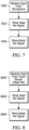
Figures 6-8 illustrate example logic in example flow chart format consistent with present principles; -
Figure 9 schematically illustrates two users remote from each other, each "conversing" with a respective local to the users which presents the facial image and mimics the motions of the opposite user; -
Figure 10 schematically illustrates additional aspects fromFigure 9 ; -
Figures 11 and 12 illustrate example logic in example flow chart format consistent with present principles; and -
Figures 13-15 illustrate example robot vehicles consistent with present principles. -
Figure 1 shows arobot 10 that includes alower body portion 12 onpropulsion elements 14, which may be established by four micro holonomic drives. The robot may be made of lightweight metal or plastic and may be relatively small, e.g., therobot 10 can be small enough to hold by hand. - An upper body or
head portion 16 is movably coupled to thelower body portion 12 by one ormore coupling shafts 18 that can be motor driven to move thehead portion 16 relative to thelower body portion 12. Thelower body 12 andhead portion 16 can be parallelepiped-shaped as shown and may be cubic in some examples. - The
head portion 16 can be movable relative to thelower body portion 12 both rotatably and tiltably. For example, as indicated by thearrows 20, the upper body orhead portion 16 can be tiltable forward-and-back relative to thelower body portion 12, while as illustrated by thearrows 22 the upper body orhead portion 16 can be tiltable left-and-right. Also, as indicated by thearrows 24, the upper body orhead portion 16 can rotate about its vertical axis relative to thelower body portion 12. - The
front surface 26 of the upper body orhead portion 16 can be established by adisplay 28 configured to present demanded images. Opposedside surfaces 30 of the upper body orhead portion 16 may includerespective microphones 32 at locations corresponding to where the ears of a human would be. Therobot 10, e.g., thelower body portion 12 thereof, can also include left andright cameras 34 which may be red-green-blue (RGB) cameras, depth cameras, or combinations thereof. The cameras alternately may be placed in thehead portion 16 where the eyes of a human would be. Aspeaker 36 may be provided on the robot, e.g., on thehead portion 16 near where the mouth of a human would be, and at least onetouch sensor 38 can be mounted on therobot 10, e.g., on the top surface of the upper body orhead portion 16 to receive touch input for a processor within therobot 10 and discussed further below. - A
control device 40 such as a smart phone may include processors, cameras, network interfaces, and the like for controlling and communicating with therobot 10 as discussed more fully herein. -
Figures 2 and 3 illustrate that thedisplay 28 of the upper body orhead portion 16 may present various different demanded images of, e.g., human faces imaged by any of the cameras herein. The images may be presented under control of any of the processors discussed herein and may be received by a network interface in therobot 10. In lieu of an image of the person, the face of an avatar representing the person may be presented to preserve privacy. The avatar may be animated to have the same emotional expressions of the person by face emotion capture (including eyes, eyebrows, mouth, and nose). - Note that whether the
head portion 12 is facing straight ahead as inFigure 2 or is tilted or rotated to one side as inFigure 3 , thedisplay 28 presents the full-face image (of the person or the avatar), even if the original image is of a human taken from the side of the human's face. Details are discussed further below. -
Figure 4 illustrates a motorized vehicle 400 (powered by, e.g., an internal rechargeable battery) with arecess 402 configured to closely hold thelower body portion 12 of therobot 10 to transport therobot 10. At least onemagnet 404 can be disposed in therecess 402 to magnetically and electrically couple the robot 10 (which can include a magnet or ferromagnet) with the motorizedvehicle 400 and to charge at least one battery in the robot. Advantageously, thepropulsion elements 14 of therobot 10 need not be detached to secure therobot 10 in therecess 402. The processor of therobot 10 senses the presence of a processor in thevehicle 400 and controls the processor in thevehicle 400 to move thevehicle 400 in lieu of moving therobot 10 by means of thepropulsion element 14. -
Figure 5 illustrates various components of therobot 10 many of which are internal to therobot 10. In addition to the camera(s) 34, microphone(s) 32, display(s) 28, speaker(s) 36, and touch surface(s) 38, therobot 10 may include one ormore processors 500 accessing one ormore computer storages 502 to program theprocessor 500 with instructions executable to undertake logic discussed herein. Theprocessor 500 may control the components illustrated inFigure 5 , including a head actuator 504 to move thehead portion 16 relative to thebody portion 12, apropulsion motor 506 to activate thepropulsion elements 14 shown inFigure 1 , and anetwork interface 508 such as a wireless transceiver to communicate data to components external to therobot 10. - A
charge circuit 510 may be provided to charge one ormore batteries 512 to provide power to the components of the robot. As discussed above, thecharge circuit 510 may receive charge current via one or moremagnetic elements 514 from, e.g., thevehicle 400 shown inFigure 4 . -
Figures 6-8 illustrate example logic in example flow chart format that theprocessor 500 inFigure 5 may execute. Commencing atbock 600 inFigure 6 , input may be received from the camera(s) 34. Face recognition may be executed on images from the camera, for example, to move thehead 16 atblock 602 to remain facing a person imaged by the camera. Also, atblock 604 the robot may be activated to move on thepropulsion elements 14 according to the camera signal, e.g., to turn and "hide" behind a nearby object as if "shy" in the presence of the person being imaged by the camera. - Commencing at
bock 700 inFigure 7 , input may be received from the microphone(s) 32. Voice recognition may be executed on the signals, for example, to move thehead 16 atblock 702 to cock one of the side of the head of the robot toward the source of the signals (or toward the face of a person imaged by the cameras) as if listening attentively to the person. Also, atblock 704 the robot may be activated to move on thepropulsion elements 14 according to the microphone signal, e.g., to turn and approach a person being imaged by the camera. - Commencing at
bock 800 inFigure 8 , input may be received from the touch surface(s) 38. Atblock 802 the processor may actuate thehead 16 to move in response to the touch signal, e.g., to bow the head as if in respect to the person touching the head. Also, atblock 804 the robot may be activated to move on thepropulsion elements 14 according to the touch signal. -
Figure 9 illustrates a use case of therobot 10. Afirst user 900 may operate a smart phone or tablet computer orother control device 902 to communicate with afirst robot 10A. Remote from thefirst user 900, asecond user 904 may operate a smart phone or tablet computer orother control device 904 to communicate with asecond robot 10B. - As indicated in
Figure 9 , thefirst robot 10A presents on its display 28 a full-face image 908 of the (frowning) second user 904 (equivalently, a frowning avatar face). Thesecond robot 10B presents on its display 28 a full-face image 910 of the (smiling) first user 900 (equivalently, a smiling avatar face). Theimage 908 on the display of thefirst robot 10A may represent thesecond user 904 based on images generated by a camera in the seconduser control device 908 or a camera in thesecond robot 10B and communicated over, e.g., a wide area computer network or a telephony network to thefirst robot 10A. Likewise, theimage 910 on the display of thesecond robot 10B may represent thefirst user 900 based on images generated by a camera in the firstuser control device 902 or thefirst robot 10A and communicated over, e.g., a wide area computer network or a telephony network to thesecond robot 10B. The face images of the users/avatars may be 2D or 3D and thedisplays 28 of the robots may be 2D displays or 3D displays. - Moreover, the head of the
first robot 10A may be controlled by the processor in thefirst control device 902 and/or thefirst robot 10A to rotate and tilt in synchronization with the head of thesecond user 904 as indicated by images from thesecond control device 906 and/orsecond robot 10B. Likewise, the head of thesecond robot 10B may be controlled by the processor in thesecond control device 906 and/or thesecond robot 10B to rotate and tilt in synchronization with the head of thefirst user 900 as indicated by images from thefirst control device 902 and/orfirst robot 10A. - In both cases, however, the image of the faces on the robots remain full-face images as would be seen from a direction normal (perpendicular) to the
display 28 from in front of the display, regardless of the orientation of the head of the respective robot. The full-face images are cropped from any background in the images of the respective user and are also cropped from body parts of the respective below the chin that may appear in the images. The full face images may be generated even as the head of the respective user turns away from the imaging camera consistent with disclosure herein, so that the front display surface of the robots present not profile images as generated by the cameras but full face images derived as described herein from camera images of a turned head no matter how the robot head is turned or tilted, just as a human face of a turned head remains a full face when viewed from directly in front of the face from a line of sight perpendicular to the face. - As below-the-head images of a user indicate movement (such as but not limited to translational movement) of the user, the corresponding (remote) robot may also move in the direction indicated by the images by activating the propulsion motor and, hence,
propulsion elements 14 of the robot. In particular, the body portion of the robot below the display may move. Further, speech from thefirst user 900 as detected by thefirst control device 902 orfirst robot 10A may be sent to thesecond robots 10B for play on the speaker on the second robot, and vice-versa. - Thus, the
first user 900 may interact with thefirst robot 10A presenting the face image of the second (remote)user 904 as if thesecond user 904 were located at the position of thefirst robot 10A, i.e., local to thefirst user 900. Likewise, thesecond user 904 may interact with thesecond robot 10B presenting the face image of the first (remote)user 900 as if thefirst user 900 were located at the position of thesecond robot 10B, i.e., local to thesecond user 904. -
Figure 10 further illustrates the above principles, assuming that user images are employed, it being understood that the same principles apply when avatars expressing the user emotion are used. At 1000 thefirst user 900 ofFigure 9 operating thefirst control device 902 is imaged using any of the cameras discussed previously to move thesecond robot 10B and to send an image of the face of thefirst user 900 to thedisplay 28 of thesecond robot 10B for presentation of a full-face image (and only a full-face image) on thesecond robot 10B. The image may be sent to a network address of thesecond robot 10B or sent to thesecond control device 906 shown inFigure 9 , which relays the image to thesecond robot 10B via, e.g., Wi-Fi or Bluetooth. No background apart from the face image and no body portions of thefirst user 900 other than the face are presented on thedisplay 28 of thesecond robot 10B. - As shown at 1002, should the
first user 900 turn his head to the left, this motion is captured, e.g., by the camera(s) in thefirst control device 902 and/orfirst robot 10A and signals such as a stream of images are sent to thesecond robot 10B as described above to cause theprocessor 500 of thesecond robot 10B to activate the head actuator 504 to turn thehead 16 of thesecond robot 10B to the left relative to thebody 12 of thesecond robot 10B, as illustrated inFigure 10 . However, thedisplay 28 of thesecond robot 10B, although turned to the left relative to the front of thebody 12, does not show a profile view of the head of thefirst user 900 as currently being imaged by the camera(s) of thefirst control device 902 orfirst robot 10A. Instead, as shown inFigure 10 thedisplay 28 of thesecond robot 10B continues to show a full-face image, i.e., an image of the face of thefirst user 900 as would be seen if looking directly at the face from a line of sight perpendicular to the face. -
Figure 11 illustrates further principles that may be used in connection with the above description. Commencing atblock 1100, an input set of training images is input to a machine learning (ML) model, such as one or more of a convolutional neural network (CNN), recurrent NN (RNN), and combinations thereof. The ML model is trained using the training set atblock 1102. - The training set of images may include 3D images of human faces from various perspectives, from full frontal view through full side profile views. The training set of images may include ground truth 2D full frontal view representations of each 3D perspective view including non-full frontal 3D perspective views. The ground truth 2D images are face-only, configured to fill an
entire display 28 of arobot 10, with background and body portions other than the face cropped out from the corresponding 3D images. The full-frontal view representations show facial features as well as emotional distortions of facial muscles (smiling, frowning, etc.). In this way, the ML model learns how to generate full frontal view 2D images from a series of 3D images of a user's face as the user turns his head toward and away from a camera rendering the 3D images. - Accordingly, present principles may employ machine learning models, including deep learning models. Machine learning models use various algorithms trained in ways that include supervised learning, unsupervised learning, semi-supervised learning, reinforcement learning, feature learning, self-learning, and other forms of learning. Examples of such algorithms, which can be implemented by computer circuitry, include one or more neural networks, such as a convolutional neural network (CNN), recurrent neural network (RNN) which may be appropriate to learn information from a series of images, and a type of RNN known as a long short-term memory (LSTM) network. Support vector machines (SVM) and Bayesian networks also may be considered to be examples of machine learning models.
- As understood herein, performing machine learning involves accessing and then training a model on training data to enable the model to process further data to make predictions. A neural network may include an input layer, an output layer, and multiple hidden layers in between that that are configured and weighted to make inferences about an appropriate output.
-
Figure 12 illustrates logic attendant toFigures 9 and10 using a ML model as trained inFigure 11 . It is to be understood that the logic ofFigure 12 may be executed by any of the processors or combinations thereof described herein, including the processor of a server on a wide area computer network communicating with thecontrol devices robots - Commencing at
block 1200, for each user (assume only twousers Figure 9 for simplicity) images are captured atbock 1202 of the user's face, including images showing motion of the face and body of the user. The voice of the user is captured atblock 1204 and both the voice signals and image sequence of the user as the user moves and speaks are sent atblock 1206 to the other user's local robot. - Meanwhile and proceeding to block 1208, the same signals - image sequences of the face and body motions and voice signals of the other user - are received at
block 1208. The image of the face of the other user, if not already full face as would be seen looking directly at the other user along a line of sight perpendicular to the front of the face of the other user, is converted atblock 1210 to a 2D full face image using the ML model trained as described, with background and body parts of the other user other than the face being cropped. The full face 2D image is presented on thedisplay 28 of the local robot preferably by entirely filling the display with the image of the face of the other user. As mentioned above, conversion of a 3D image in profile of a user's face to a full face 2D image may be effected by any one or more of the processors described herein. - In an alternative embodiment, in lieu of using ML models to convert 3D images to full face 2D images, a single 2D full face image of the other user may be obtained and presented for the duration on the local robot. As also discussed, avatars may be used for privacy instead of the image of a person, with the expression of the avatars preferably being animated according to the expression of the person.
- If desired, the other user's voice may be played at
block 1212 on the local robot or the local control device. Also, atblock 1214 the head of the local robot may be turned to mimic head motion of the other user as represented by the sequence of images received atblock 1208 and as shown at 1002 inFigure 10 . Moreover, in the event that the other user moves his body by, e.g., walking, that motion is captured and received atblock 1208 and input to the processor of the local robot to actuate the propulsion elements 14 (or, if the robot is in a vehicle such as thevehicle 400 shown inFigure 4 , the vehicle) to translationally move the local robot to mimic the motion of the other user. -
Figures 13-15 indicate that in lieu of themotorized vehicle 400 shown inFigure 4 , therobot 10 may be mounted on other types of moving platforms such as a bicycle 1300, a crab-like tractor 1400, or an airborne drone 1500. - Components included in one embodiment can be used in other embodiments in any appropriate combination. For example, any of the various components described herein and/or depicted in the Figures may be combined, interchanged, or excluded from other embodiments.
- "A system having at least one of A, B, and C" (likewise "a system having at least one of A, B, or C" and "a system having at least one of A, B, C") includes systems that have A alone, B alone, C alone, A and B together, A and C together, B and C together, and/or A, B, and C together, etc.
- A processor may be a single- or multi-chip processor that can execute logic by means of various lines such as address lines, data lines, and control lines and registers and shift registers.
- Network interfaces such as transceivers may be configured for communication over at least one network such as the Internet, a WAN, a LAN, etc. An interface may be, without limitation, a Wi-Fi transceiver, Bluetooth® transceiver, near filed communication transceiver, wireless telephony transceiver, etc.
- Computer storage may be embodied by computer memories such as disk-based or solid-state storage that are not transitory signals.
- While the particular robot is herein shown and described in detail, it is to be understood that the subject matter which is encompassed by the present invention is limited only by the claims.
Claims (15)
- A robot, comprising:a lower body portion on propulsion elements;an upper body portion coupled to the lower body portion and movable relative to the lower body portion, the upper body portion comprising:
at least one display configured to present an image representing a person remote from the robot, the image being a full-face image. - The robot of Claim 1, wherein the upper body portion is movable relative to the lower body portion in accordance with motion of the person as indicated by signals received from an imager imaging the person.
- The robot of Claim 1, wherein the full-face image is generated from a profile image of the person.
- The robot of Claim 1, wherein the full-face image is generated from a profile image of the person using a machine learning (ML) model.
- The robot of Claim 1, wherein the robot comprises at least one camera and comprises at least one processor to send images from the camera to a companion robot local to and associated with the person.
- The robot of Claim 1, comprising a motorized vehicle with a recess configured to closely hold the lower body portion to transport the robot, at least one magnet being disposed in the recess to magnetically couple the robot with the motorized vehicle and to charge at least one battery in the robot.
- The robot of Claim 1, comprising at least one touch sensor on a top surface of the upper body portion to receive touch input for the processor.
- The robot of Claim 1, wherein the propulsion elements comprise micro holonomic drives.
- A device comprising:
at least one computer storage that is not a transitory signal and that comprises instructions executable by at least one processor to:for at least a first user, render, from at least one image captured of the first user by at least one imager, a full-face image representing the first user with background and body parts of the first user cropped out of the image representing the first user;provide, to at least a first robot remote from the first user, the full-face image for presentation thereof on a display of the first robot with the full-face image filling the display;provide, to the first robot, information from the imager regarding motion of the first user such that a head of the first robot turns to mimic the motion of the first user while continuing to present the full-face image the display of the first robot regardless of whether the head of the first user turned away from the imager. - The device of Claim 9, comprising the at least one processor embodied in the first robot.
- The device of Claim 9, wherein the instructions are executable to:
provide to the first robot voice signals from the first user to enable the first robot to play the voice signals on at least one speaker of the first robot. - The device of Claim 9, wherein the first robot comprises a body portion movably engaged with the display, and the instructions are executable to:
provide to the first robot signals from the imager representing below-the-head movement of the first user to cause the body portion of the first robot to move according to the below-the-head movement of the first user. - The device of Claim 9, wherein the instructions are executable to:for at least a second user who is local to the first robot, render, from at least one image captured of the second user by at least one imaging device, a full-face image representing the second user with background and body parts of the second user cropped out of the image representing the second user;provide, to at least a second robot remote from the second user and local to the first user, the full-face image representing second user for presentation thereof on a display of the second robot with the full-face image representing the second user filling the display of the second robot;provide, to the second robot, information from the imaging device regarding motion of the second user such that a head of the second robot turns to mimic the motion of the second user while continuing to present a full-face image representing the second user on the display of the second robot regardless of whether the head of the second user turned away from the imaging device.
- A method, comprising:for at least a first user, rendering, from at least one image captured of the first user, a full-face image representing the first user with background and body parts of the first user cropped out of the full-face image;presenting, on at least one display of a first robot remote from the first user, the full-face image representing the first user with the full-face image filling the display of the first robot;turning a head of the first robot to mimic a head turn of the first user while continuing to present a full-face image representing the first user on the display of the first robot;for at least a second user local to the first robot, rendering, from at least one image captured of the second user, a full-face image representing the second user with background and body parts of the second user cropped out of the image representing the second user;presenting, on at least one display of a second robot local to the first user, the full-face image representing the second user with the full-face image representing the second user filling the display of the second robot; andturning a head of the second robot to mimic a head turn of the second user while continuing to present a full-face image representing the second user on the display of the second robot.
- The method of Claim 14, comprising:presenting audio generated by the first user on the second robot; andpresenting audio generated by the second user on the first robot.
Applications Claiming Priority (1)
| Application Number | Priority Date | Filing Date | Title |
|---|---|---|---|
| US17/390,887 US20230030442A1 (en) | 2021-07-31 | 2021-07-31 | Telepresence robot |
Publications (2)
| Publication Number | Publication Date |
|---|---|
| EP4124416A1 true EP4124416A1 (en) | 2023-02-01 |
| EP4124416B1 EP4124416B1 (en) | 2024-11-13 |
Family
ID=83050082
Family Applications (1)
| Application Number | Title | Priority Date | Filing Date |
|---|---|---|---|
| EP22187604.8A Active EP4124416B1 (en) | 2021-07-31 | 2022-07-28 | Telepresence robot |
Country Status (5)
| Country | Link |
|---|---|
| US (1) | US20230030442A1 (en) |
| EP (1) | EP4124416B1 (en) |
| JP (1) | JP2023021207A (en) |
| CN (1) | CN115922657A (en) |
| TW (1) | TWI886401B (en) |
Citations (6)
| Publication number | Priority date | Publication date | Assignee | Title |
|---|---|---|---|---|
| US20120239196A1 (en) * | 2011-03-15 | 2012-09-20 | Microsoft Corporation | Natural Human to Robot Remote Control |
| US20180137678A1 (en) * | 2016-11-11 | 2018-05-17 | Magic Leap, Inc. | Periocular and audio synthesis of a full face image |
| US20190285881A1 (en) * | 2018-03-16 | 2019-09-19 | Magic Leap, Inc. | Facial expressions from eye-tracking cameras |
| US20190366558A1 (en) * | 2018-06-01 | 2019-12-05 | Irepa International, LLC | Autonomous companion mobile robot and system |
| US20200130194A1 (en) * | 2018-10-24 | 2020-04-30 | Toyota Jidosha Kabushiki Kaisha | Communication robot and control program of communication robot |
| US11065769B2 (en) * | 2018-09-14 | 2021-07-20 | Lg Electronics Inc. | Robot, method for operating the same, and server connected thereto |
Family Cites Families (8)
| Publication number | Priority date | Publication date | Assignee | Title |
|---|---|---|---|---|
| EP1122038A4 (en) * | 1998-06-23 | 2009-06-17 | Sony Corp | ROBOT AND INFORMATION PROCESSING SYSTEM |
| US8077963B2 (en) * | 2004-07-13 | 2011-12-13 | Yulun Wang | Mobile robot with a head-based movement mapping scheme |
| US10775880B2 (en) * | 2016-11-30 | 2020-09-15 | Universal City Studios Llc | Animated character head systems and methods |
| US20180229372A1 (en) * | 2017-02-10 | 2018-08-16 | JIBO, Inc. | Maintaining attention and conveying believability via expression and goal-directed behavior with a social robot |
| JP2018176387A (en) * | 2017-04-19 | 2018-11-15 | 富士ゼロックス株式会社 | Robot device and program |
| CN109093627A (en) * | 2017-06-21 | 2018-12-28 | 富泰华工业(深圳)有限公司 | intelligent robot |
| KR102102685B1 (en) * | 2018-04-18 | 2020-04-23 | 한국생산기술연구원 | A method for robotic facial expressions by learning human facial demonstrations |
| US11203122B2 (en) * | 2018-08-03 | 2021-12-21 | Digital Dream Labs, Llc | Goal-based robot animation |
-
2021
- 2021-07-31 US US17/390,887 patent/US20230030442A1/en not_active Abandoned
-
2022
- 2022-07-15 TW TW111126652A patent/TWI886401B/en active
- 2022-07-22 CN CN202210867160.0A patent/CN115922657A/en active Pending
- 2022-07-26 JP JP2022118491A patent/JP2023021207A/en active Pending
- 2022-07-28 EP EP22187604.8A patent/EP4124416B1/en active Active
Patent Citations (6)
| Publication number | Priority date | Publication date | Assignee | Title |
|---|---|---|---|---|
| US20120239196A1 (en) * | 2011-03-15 | 2012-09-20 | Microsoft Corporation | Natural Human to Robot Remote Control |
| US20180137678A1 (en) * | 2016-11-11 | 2018-05-17 | Magic Leap, Inc. | Periocular and audio synthesis of a full face image |
| US20190285881A1 (en) * | 2018-03-16 | 2019-09-19 | Magic Leap, Inc. | Facial expressions from eye-tracking cameras |
| US20190366558A1 (en) * | 2018-06-01 | 2019-12-05 | Irepa International, LLC | Autonomous companion mobile robot and system |
| US11065769B2 (en) * | 2018-09-14 | 2021-07-20 | Lg Electronics Inc. | Robot, method for operating the same, and server connected thereto |
| US20200130194A1 (en) * | 2018-10-24 | 2020-04-30 | Toyota Jidosha Kabushiki Kaisha | Communication robot and control program of communication robot |
Also Published As
| Publication number | Publication date |
|---|---|
| EP4124416B1 (en) | 2024-11-13 |
| TWI886401B (en) | 2025-06-11 |
| JP2023021207A (en) | 2023-02-10 |
| CN115922657A (en) | 2023-04-07 |
| TW202309832A (en) | 2023-03-01 |
| US20230030442A1 (en) | 2023-02-02 |
Similar Documents
| Publication | Publication Date | Title |
|---|---|---|
| US11381775B2 (en) | Light field display system for video communication including holographic content | |
| EP3624442A1 (en) | Robot and method for operating the same | |
| EP3623118B1 (en) | Emotion recognizer, robot including the same, and server including the same | |
| KR102242779B1 (en) | Robot and method for operating the same | |
| US11783531B2 (en) | Method, system, and medium for 3D or 2.5D electronic communication | |
| US10334158B2 (en) | Autonomous media capturing | |
| KR102741760B1 (en) | Artificial intelligence device that can be controlled according to user gaze | |
| US11065769B2 (en) | Robot, method for operating the same, and server connected thereto | |
| JP4512830B2 (en) | Communication robot | |
| JP6565853B2 (en) | Communication device | |
| EP4124416B1 (en) | Telepresence robot | |
| JP2022519490A (en) | Teleconference device | |
| US11810219B2 (en) | Multi-user and multi-surrogate virtual encounters | |
| CN116931728A (en) | Multimode man-machine interaction control system and method for humanoid robot | |
| US20250211457A1 (en) | Telepresence with a human avatar | |
| JP2017164854A (en) | Robot and program | |
| US20250291412A1 (en) | Display system, display method, and storage medium | |
| US20250291408A1 (en) | Display system, display method, and storage medium | |
| US20250088380A1 (en) | Communication systems and methods | |
| CN108748260A (en) | A kind of audiovisual interactive intelligence robot | |
| US20250227362A1 (en) | Information processing apparatus, information processing method, and recording medium | |
| WO2024163006A1 (en) | Methods and systems for constructing facial images using partial images | |
| CN118092630A (en) | Wearable device, facial image reconstruction method and device and storage medium |
Legal Events
| Date | Code | Title | Description |
|---|---|---|---|
| PUAI | Public reference made under article 153(3) epc to a published international application that has entered the european phase |
Free format text: ORIGINAL CODE: 0009012 |
|
| STAA | Information on the status of an ep patent application or granted ep patent |
Free format text: STATUS: REQUEST FOR EXAMINATION WAS MADE |
|
| 17P | Request for examination filed |
Effective date: 20220814 |
|
| AK | Designated contracting states |
Kind code of ref document: A1 Designated state(s): AL AT BE BG CH CY CZ DE DK EE ES FI FR GB GR HR HU IE IS IT LI LT LU LV MC MK MT NL NO PL PT RO RS SE SI SK SM TR |
|
| STAA | Information on the status of an ep patent application or granted ep patent |
Free format text: STATUS: EXAMINATION IS IN PROGRESS |
|
| 17Q | First examination report despatched |
Effective date: 20231110 |
|
| GRAP | Despatch of communication of intention to grant a patent |
Free format text: ORIGINAL CODE: EPIDOSNIGR1 |
|
| STAA | Information on the status of an ep patent application or granted ep patent |
Free format text: STATUS: GRANT OF PATENT IS INTENDED |
|
| INTG | Intention to grant announced |
Effective date: 20240618 |
|
| GRAS | Grant fee paid |
Free format text: ORIGINAL CODE: EPIDOSNIGR3 |
|
| GRAA | (expected) grant |
Free format text: ORIGINAL CODE: 0009210 |
|
| STAA | Information on the status of an ep patent application or granted ep patent |
Free format text: STATUS: THE PATENT HAS BEEN GRANTED |
|
| AK | Designated contracting states |
Kind code of ref document: B1 Designated state(s): AL AT BE BG CH CY CZ DE DK EE ES FI FR GB GR HR HU IE IS IT LI LT LU LV MC MK MT NL NO PL PT RO RS SE SI SK SM TR |
|
| P01 | Opt-out of the competence of the unified patent court (upc) registered |
Free format text: CASE NUMBER: APP_54817/2024 Effective date: 20241004 |
|
| REG | Reference to a national code |
Ref country code: GB Ref legal event code: FG4D |
|
| REG | Reference to a national code |
Ref country code: CH Ref legal event code: EP |
|
| REG | Reference to a national code |
Ref country code: IE Ref legal event code: FG4D |
|
| REG | Reference to a national code |
Ref country code: DE Ref legal event code: R096 Ref document number: 602022007649 Country of ref document: DE |
|
| REG | Reference to a national code |
Ref country code: LT Ref legal event code: MG9D |
|
| REG | Reference to a national code |
Ref country code: NL Ref legal event code: MP Effective date: 20241113 |
|
| PG25 | Lapsed in a contracting state [announced via postgrant information from national office to epo] |
Ref country code: IS Free format text: LAPSE BECAUSE OF FAILURE TO SUBMIT A TRANSLATION OF THE DESCRIPTION OR TO PAY THE FEE WITHIN THE PRESCRIBED TIME-LIMIT Effective date: 20250313 Ref country code: HR Free format text: LAPSE BECAUSE OF FAILURE TO SUBMIT A TRANSLATION OF THE DESCRIPTION OR TO PAY THE FEE WITHIN THE PRESCRIBED TIME-LIMIT Effective date: 20241113 Ref country code: PT Free format text: LAPSE BECAUSE OF FAILURE TO SUBMIT A TRANSLATION OF THE DESCRIPTION OR TO PAY THE FEE WITHIN THE PRESCRIBED TIME-LIMIT Effective date: 20250313 |
|
| PG25 | Lapsed in a contracting state [announced via postgrant information from national office to epo] |
Ref country code: FI Free format text: LAPSE BECAUSE OF FAILURE TO SUBMIT A TRANSLATION OF THE DESCRIPTION OR TO PAY THE FEE WITHIN THE PRESCRIBED TIME-LIMIT Effective date: 20241113 Ref country code: NL Free format text: LAPSE BECAUSE OF FAILURE TO SUBMIT A TRANSLATION OF THE DESCRIPTION OR TO PAY THE FEE WITHIN THE PRESCRIBED TIME-LIMIT Effective date: 20241113 |
|
| REG | Reference to a national code |
Ref country code: AT Ref legal event code: MK05 Ref document number: 1741332 Country of ref document: AT Kind code of ref document: T Effective date: 20241113 |
|
| PG25 | Lapsed in a contracting state [announced via postgrant information from national office to epo] |
Ref country code: BG Free format text: LAPSE BECAUSE OF FAILURE TO SUBMIT A TRANSLATION OF THE DESCRIPTION OR TO PAY THE FEE WITHIN THE PRESCRIBED TIME-LIMIT Effective date: 20241113 |
|
| PG25 | Lapsed in a contracting state [announced via postgrant information from national office to epo] |
Ref country code: ES Free format text: LAPSE BECAUSE OF FAILURE TO SUBMIT A TRANSLATION OF THE DESCRIPTION OR TO PAY THE FEE WITHIN THE PRESCRIBED TIME-LIMIT Effective date: 20241113 |
|
| PG25 | Lapsed in a contracting state [announced via postgrant information from national office to epo] |
Ref country code: NO Free format text: LAPSE BECAUSE OF FAILURE TO SUBMIT A TRANSLATION OF THE DESCRIPTION OR TO PAY THE FEE WITHIN THE PRESCRIBED TIME-LIMIT Effective date: 20250213 |
|
| PG25 | Lapsed in a contracting state [announced via postgrant information from national office to epo] |
Ref country code: LV Free format text: LAPSE BECAUSE OF FAILURE TO SUBMIT A TRANSLATION OF THE DESCRIPTION OR TO PAY THE FEE WITHIN THE PRESCRIBED TIME-LIMIT Effective date: 20241113 Ref country code: AT Free format text: LAPSE BECAUSE OF FAILURE TO SUBMIT A TRANSLATION OF THE DESCRIPTION OR TO PAY THE FEE WITHIN THE PRESCRIBED TIME-LIMIT Effective date: 20241113 Ref country code: GR Free format text: LAPSE BECAUSE OF FAILURE TO SUBMIT A TRANSLATION OF THE DESCRIPTION OR TO PAY THE FEE WITHIN THE PRESCRIBED TIME-LIMIT Effective date: 20250214 |
|
| PG25 | Lapsed in a contracting state [announced via postgrant information from national office to epo] |
Ref country code: PL Free format text: LAPSE BECAUSE OF FAILURE TO SUBMIT A TRANSLATION OF THE DESCRIPTION OR TO PAY THE FEE WITHIN THE PRESCRIBED TIME-LIMIT Effective date: 20241113 |
|
| PG25 | Lapsed in a contracting state [announced via postgrant information from national office to epo] |
Ref country code: RS Free format text: LAPSE BECAUSE OF FAILURE TO SUBMIT A TRANSLATION OF THE DESCRIPTION OR TO PAY THE FEE WITHIN THE PRESCRIBED TIME-LIMIT Effective date: 20250213 |
|
| PG25 | Lapsed in a contracting state [announced via postgrant information from national office to epo] |
Ref country code: SM Free format text: LAPSE BECAUSE OF FAILURE TO SUBMIT A TRANSLATION OF THE DESCRIPTION OR TO PAY THE FEE WITHIN THE PRESCRIBED TIME-LIMIT Effective date: 20241113 |
|
| PG25 | Lapsed in a contracting state [announced via postgrant information from national office to epo] |
Ref country code: DK Free format text: LAPSE BECAUSE OF FAILURE TO SUBMIT A TRANSLATION OF THE DESCRIPTION OR TO PAY THE FEE WITHIN THE PRESCRIBED TIME-LIMIT Effective date: 20241113 |
|
| PG25 | Lapsed in a contracting state [announced via postgrant information from national office to epo] |
Ref country code: EE Free format text: LAPSE BECAUSE OF FAILURE TO SUBMIT A TRANSLATION OF THE DESCRIPTION OR TO PAY THE FEE WITHIN THE PRESCRIBED TIME-LIMIT Effective date: 20241113 |
|
| PGFP | Annual fee paid to national office [announced via postgrant information from national office to epo] |
Ref country code: FR Payment date: 20250620 Year of fee payment: 4 |
|
| PG25 | Lapsed in a contracting state [announced via postgrant information from national office to epo] |
Ref country code: RO Free format text: LAPSE BECAUSE OF FAILURE TO SUBMIT A TRANSLATION OF THE DESCRIPTION OR TO PAY THE FEE WITHIN THE PRESCRIBED TIME-LIMIT Effective date: 20241113 |
|
| PG25 | Lapsed in a contracting state [announced via postgrant information from national office to epo] |
Ref country code: SK Free format text: LAPSE BECAUSE OF FAILURE TO SUBMIT A TRANSLATION OF THE DESCRIPTION OR TO PAY THE FEE WITHIN THE PRESCRIBED TIME-LIMIT Effective date: 20241113 |
|
| PG25 | Lapsed in a contracting state [announced via postgrant information from national office to epo] |
Ref country code: CZ Free format text: LAPSE BECAUSE OF FAILURE TO SUBMIT A TRANSLATION OF THE DESCRIPTION OR TO PAY THE FEE WITHIN THE PRESCRIBED TIME-LIMIT Effective date: 20241113 |
|
| PG25 | Lapsed in a contracting state [announced via postgrant information from national office to epo] |
Ref country code: IT Free format text: LAPSE BECAUSE OF FAILURE TO SUBMIT A TRANSLATION OF THE DESCRIPTION OR TO PAY THE FEE WITHIN THE PRESCRIBED TIME-LIMIT Effective date: 20241113 |
|
| REG | Reference to a national code |
Ref country code: DE Ref legal event code: R097 Ref document number: 602022007649 Country of ref document: DE |
|
| PG25 | Lapsed in a contracting state [announced via postgrant information from national office to epo] |
Ref country code: SE Free format text: LAPSE BECAUSE OF FAILURE TO SUBMIT A TRANSLATION OF THE DESCRIPTION OR TO PAY THE FEE WITHIN THE PRESCRIBED TIME-LIMIT Effective date: 20241113 |
|
| PLBE | No opposition filed within time limit |
Free format text: ORIGINAL CODE: 0009261 |
|
| STAA | Information on the status of an ep patent application or granted ep patent |
Free format text: STATUS: NO OPPOSITION FILED WITHIN TIME LIMIT |
|
| PGFP | Annual fee paid to national office [announced via postgrant information from national office to epo] |
Ref country code: DE Payment date: 20250620 Year of fee payment: 4 |
|
| 26N | No opposition filed |
Effective date: 20250814 |
|
| REG | Reference to a national code |
Ref country code: CH Ref legal event code: H13 Free format text: ST27 STATUS EVENT CODE: U-0-0-H10-H13 (AS PROVIDED BY THE NATIONAL OFFICE) Effective date: 20260224 |
|
| PG25 | Lapsed in a contracting state [announced via postgrant information from national office to epo] |
Ref country code: LU Free format text: LAPSE BECAUSE OF NON-PAYMENT OF DUE FEES Effective date: 20250728 |
|
| REG | Reference to a national code |
Ref country code: BE Ref legal event code: MM Effective date: 20250731 |
|
| PG25 | Lapsed in a contracting state [announced via postgrant information from national office to epo] |
Ref country code: BE Free format text: LAPSE BECAUSE OF NON-PAYMENT OF DUE FEES Effective date: 20250731 |
|
| PG25 | Lapsed in a contracting state [announced via postgrant information from national office to epo] |
Ref country code: CH Free format text: LAPSE BECAUSE OF NON-PAYMENT OF DUE FEES Effective date: 20250731 |