EP4124414A1 - Stapler and device with a lubricant flow path - Google Patents
Stapler and device with a lubricant flow path Download PDFInfo
- Publication number
- EP4124414A1 EP4124414A1 EP22186928.2A EP22186928A EP4124414A1 EP 4124414 A1 EP4124414 A1 EP 4124414A1 EP 22186928 A EP22186928 A EP 22186928A EP 4124414 A1 EP4124414 A1 EP 4124414A1
- Authority
- EP
- European Patent Office
- Prior art keywords
- flow path
- lubricant
- accommodating portion
- cam
- shaft
- Prior art date
- Legal status (The legal status is an assumption and is not a legal conclusion. Google has not performed a legal analysis and makes no representation as to the accuracy of the status listed.)
- Granted
Links
Images





Classifications
-
- B—PERFORMING OPERATIONS; TRANSPORTING
- B25—HAND TOOLS; PORTABLE POWER-DRIVEN TOOLS; MANIPULATORS
- B25F—COMBINATION OR MULTI-PURPOSE TOOLS NOT OTHERWISE PROVIDED FOR; DETAILS OR COMPONENTS OF PORTABLE POWER-DRIVEN TOOLS NOT PARTICULARLY RELATED TO THE OPERATIONS PERFORMED AND NOT OTHERWISE PROVIDED FOR
- B25F5/00—Details or components of portable power-driven tools not particularly related to the operations performed and not otherwise provided for
- B25F5/001—Gearings, speed selectors, clutches or the like specially adapted for rotary tools
-
- B—PERFORMING OPERATIONS; TRANSPORTING
- B25—HAND TOOLS; PORTABLE POWER-DRIVEN TOOLS; MANIPULATORS
- B25C—HAND-HELD NAILING OR STAPLING TOOLS; MANUALLY OPERATED PORTABLE STAPLING TOOLS
- B25C5/00—Manually operated portable stapling tools; Hand-held power-operated stapling tools; Staple feeding devices therefor
- B25C5/02—Manually operated portable stapling tools; Hand-held power-operated stapling tools; Staple feeding devices therefor with provision for bending the ends of the staples on to the work
- B25C5/0285—Hand-held stapling tools, e.g. manually operated, i.e. not resting on a working surface during operation
-
- B—PERFORMING OPERATIONS; TRANSPORTING
- B25—HAND TOOLS; PORTABLE POWER-DRIVEN TOOLS; MANIPULATORS
- B25C—HAND-HELD NAILING OR STAPLING TOOLS; MANUALLY OPERATED PORTABLE STAPLING TOOLS
- B25C1/00—Hand-held nailing tools; Nail feeding devices
- B25C1/04—Hand-held nailing tools; Nail feeding devices operated by fluid pressure, e.g. by air pressure
- B25C1/047—Mechanical details
-
- B—PERFORMING OPERATIONS; TRANSPORTING
- B25—HAND TOOLS; PORTABLE POWER-DRIVEN TOOLS; MANIPULATORS
- B25C—HAND-HELD NAILING OR STAPLING TOOLS; MANUALLY OPERATED PORTABLE STAPLING TOOLS
- B25C5/00—Manually operated portable stapling tools; Hand-held power-operated stapling tools; Staple feeding devices therefor
- B25C5/10—Driving means
-
- B—PERFORMING OPERATIONS; TRANSPORTING
- B26—HAND CUTTING TOOLS; CUTTING; SEVERING
- B26D—CUTTING; DETAILS COMMON TO MACHINES FOR PERFORATING, PUNCHING, CUTTING-OUT, STAMPING-OUT OR SEVERING
- B26D5/00—Arrangements for operating and controlling machines or devices for cutting, cutting-out, stamping-out, punching, perforating, or severing by means other than cutting
- B26D5/08—Means for actuating the cutting member to effect the cut
- B26D5/16—Cam means
-
- B—PERFORMING OPERATIONS; TRANSPORTING
- B26—HAND CUTTING TOOLS; CUTTING; SEVERING
- B26D—CUTTING; DETAILS COMMON TO MACHINES FOR PERFORATING, PUNCHING, CUTTING-OUT, STAMPING-OUT OR SEVERING
- B26D7/00—Details of apparatus for cutting, cutting-out, stamping-out, punching, perforating, or severing by means other than cutting
- B26D7/08—Means for treating work or cutting member to facilitate cutting
- B26D7/088—Means for treating work or cutting member to facilitate cutting by cleaning or lubricating
-
- F—MECHANICAL ENGINEERING; LIGHTING; HEATING; WEAPONS; BLASTING
- F16—ENGINEERING ELEMENTS AND UNITS; GENERAL MEASURES FOR PRODUCING AND MAINTAINING EFFECTIVE FUNCTIONING OF MACHINES OR INSTALLATIONS; THERMAL INSULATION IN GENERAL
- F16H—GEARING
- F16H57/00—General details of gearing
- F16H57/04—Features relating to lubrication or cooling or heating
- F16H57/042—Guidance of lubricant
- F16H57/043—Guidance of lubricant within rotary parts, e.g. axial channels or radial openings in shafts
-
- F—MECHANICAL ENGINEERING; LIGHTING; HEATING; WEAPONS; BLASTING
- F16—ENGINEERING ELEMENTS AND UNITS; GENERAL MEASURES FOR PRODUCING AND MAINTAINING EFFECTIVE FUNCTIONING OF MACHINES OR INSTALLATIONS; THERMAL INSULATION IN GENERAL
- F16N—LUBRICATING
- F16N11/00—Arrangements for supplying grease from a stationary reservoir or the equivalent in or on the machine or member to be lubricated; Grease cups
-
- B—PERFORMING OPERATIONS; TRANSPORTING
- B25—HAND TOOLS; PORTABLE POWER-DRIVEN TOOLS; MANIPULATORS
- B25C—HAND-HELD NAILING OR STAPLING TOOLS; MANUALLY OPERATED PORTABLE STAPLING TOOLS
- B25C5/00—Manually operated portable stapling tools; Hand-held power-operated stapling tools; Staple feeding devices therefor
- B25C5/10—Driving means
- B25C5/13—Driving means operated by fluid pressure
-
- B—PERFORMING OPERATIONS; TRANSPORTING
- B26—HAND CUTTING TOOLS; CUTTING; SEVERING
- B26D—CUTTING; DETAILS COMMON TO MACHINES FOR PERFORATING, PUNCHING, CUTTING-OUT, STAMPING-OUT OR SEVERING
- B26D7/00—Details of apparatus for cutting, cutting-out, stamping-out, punching, perforating, or severing by means other than cutting
- B26D2007/0012—Details, accessories or auxiliary or special operations not otherwise provided for
- B26D2007/0087—Details, accessories or auxiliary or special operations not otherwise provided for for use on a desktop
-
- B—PERFORMING OPERATIONS; TRANSPORTING
- B26—HAND CUTTING TOOLS; CUTTING; SEVERING
- B26F—PERFORATING; PUNCHING; CUTTING-OUT; STAMPING-OUT; SEVERING BY MEANS OTHER THAN CUTTING
- B26F1/00—Perforating; Punching; Cutting-out; Stamping-out; Apparatus therefor
- B26F1/38—Cutting-out; Stamping-out
- B26F1/3806—Cutting-out; Stamping-out wherein relative movements of tool head and work during cutting have a component tangential to the work surface
- B26F1/3813—Cutting-out; Stamping-out wherein relative movements of tool head and work during cutting have a component tangential to the work surface wherein the tool head is moved in a plane parallel to the work in a coordinate system fixed with respect to the work
-
- B—PERFORMING OPERATIONS; TRANSPORTING
- B41—PRINTING; LINING MACHINES; TYPEWRITERS; STAMPS
- B41J—TYPEWRITERS; SELECTIVE PRINTING MECHANISMS, i.e. MECHANISMS PRINTING OTHERWISE THAN FROM A FORME; CORRECTION OF TYPOGRAPHICAL ERRORS
- B41J11/00—Devices or arrangements of selective printing mechanisms, e.g. ink-jet printers or thermal printers, for supporting or handling copy material in sheet or web form
- B41J11/66—Applications of cutting devices
-
- F—MECHANICAL ENGINEERING; LIGHTING; HEATING; WEAPONS; BLASTING
- F16—ENGINEERING ELEMENTS AND UNITS; GENERAL MEASURES FOR PRODUCING AND MAINTAINING EFFECTIVE FUNCTIONING OF MACHINES OR INSTALLATIONS; THERMAL INSULATION IN GENERAL
- F16H—GEARING
- F16H57/00—General details of gearing
- F16H57/04—Features relating to lubrication or cooling or heating
- F16H57/0463—Grease lubrication; Drop-feed lubrication
- F16H57/0464—Grease lubrication
-
- F—MECHANICAL ENGINEERING; LIGHTING; HEATING; WEAPONS; BLASTING
- F16—ENGINEERING ELEMENTS AND UNITS; GENERAL MEASURES FOR PRODUCING AND MAINTAINING EFFECTIVE FUNCTIONING OF MACHINES OR INSTALLATIONS; THERMAL INSULATION IN GENERAL
- F16N—LUBRICATING
- F16N2210/00—Applications
- F16N2210/12—Gearings
Definitions
- the accommodating portion 6 may be configured by providing a bottomed hole (recess) that does not penetrate to the back surface 23b on the front surface 23a of the first member 2.
- a bottomed hole that does not penetrate to the back surface 23b on the front surface 23a of the first member 2.
- the accommodating portion 6 may be provided in each of the plurality of flow paths 5 (for example, two accommodating portions 6 for two flow paths 5).
- the drill tool 11C includes a shaft 14C to which a driving force of the motor 13C is transmitted through a first gear 2C1, and a second gear 2C2 which transmits the driving force of the motor 13C to the rotating body 12C via the shaft 14C.
- lubricant is supplied to the teeth portion 20C where the gears mesh with each other via the flow path 5. In this way, the wear of the teeth portion 20C is suppressed.
Landscapes
- Engineering & Computer Science (AREA)
- Mechanical Engineering (AREA)
- General Engineering & Computer Science (AREA)
- Life Sciences & Earth Sciences (AREA)
- Forests & Forestry (AREA)
- Physics & Mathematics (AREA)
- Fluid Mechanics (AREA)
- Transmission Devices (AREA)
- Dovetailed Work, And Nailing Machines And Stapling Machines For Wood (AREA)
- Portable Power Tools In General (AREA)
- Sliding-Contact Bearings (AREA)
Abstract
Description
- The disclosure relates to a device including two members that move in contact with each other by relative movement.
- In a device provided with, for example, a cam mechanism, a gear mechanism, a hinge mechanism or the like, which is configured by two members (first member and second member) that move in contact with each other by relative movement, lubricant such as grease may be applied to a sliding surface in order to improve the slidability and durability of the sliding surface (contact surface) of two members. Further, a technique has been proposed in which a grease storing recess for storing grease is provided on the sliding surface of at least one of the first member and the second member so that the grease can be supplied from the grease reserving recess to the sliding surface (e.g., see
Japanese Unexamined Patent Publication No. 2011-214328 - Further, in a hinge mechanism provided with a shaft that serves as a rotating axis of a rotating member and a bracket having a cylindrical portion that wraps around an outer periphery of the shaft and obtains sliding resistance by an elastic force, a technique has been proposed in which a groove-shaped grease storing hole inclined with respect to a rotation direction of the shaft penetrates in the cylindrical portion (e.g., see
Japanese Patent No. 6272148 - However, in the technique where a grease storage is formed by providing a recess or a through hole on a sliding surface of a member, there is a problem that the volume of the grease storage must be increased and a sufficient amount of grease must be held or accommodated so that the grease is not exhausted during repeated sliding. However, when the size of the grease storage is enlarged, the area of the sliding surface is reduced. Therefore, the surface pressure increases and wear is promoted. Further, this leads to a decrease in the strength of the sliding surface.
- Therefore, the disclosure provides a device which suppresses the depletion of the lubricant on the sliding surface while suppressing a decrease in the area of the surface where the two members are in contact with each other, that is, the area of the sliding surface.
- According to an aspect of the present invention, there is provided a device including a first member having a first surface, and a second member having a second surface that is partially or wholly in contact with the first surface. The first member and the second member are configured to operate relatively. The first member has a flow path of a lubricant that has an opening provided in the first surface.
- In the device, the lubricant is supplied from the opening to the first surface of the first member in contact with the second surface of the second member through the flow path.
- According to the above-described device, since the lubricant can be held or accommodated in the flow path, it is not necessary to enlarge the opening of the first surface, and it is possible to suppress a decrease in the area of the sliding surface. Further, since a required amount of lubricant can be held in the flow path, the depletion of the lubricant can be suppressed.
-
-
FIG. 1A is a side view of a main part showing an example of a stapler as an embodiment of the device of the disclosure. -
FIG. 1B is a side view showing the example of the stapler as the embodiment of the device of the disclosure. -
FIG. 2A is a perspective view showing an example of a first member constituting the stapler of the present embodiment. -
FIG. 2B is a sectional view showing the example of the first member constituting the stapler of the present embodiment. -
FIG. 3A is a perspective view showing a modified example of the first member. -
FIG. 3B is a perspective view showing a modified example of the first member. -
FIG. 3C is a perspective view showing a modified example of the first member. -
FIG. 3D is a perspective view showing a modified example of the first member. -
FIG. 3E is a perspective view showing a modified example of the first member. -
FIG. 3F is a perspective view showing a modified example of the first member. -
FIG. 4A is a side view showing an example of an internal configuration of a driving tool as an embodiment of the device of the disclosure. -
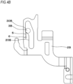
FIG. 4B is a side view showing an example of a contact arm as a first member constituting the driving tool. -
FIG. 5A is a side sectional view showing an example of an internal configuration of a drill tool as an embodiment of the device of the disclosure. -
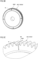
FIG. 5B is an overall perspective view showing an example of a gear as a first member constituting the drill tool. -
FIG. 5C is a perspective view of a main part showing an example of the gear as the first member constituting the drill tool. -
FIG. 6A is a side sectional view showing an example of an internal configuration of a printer as an embodiment of the device of the disclosure. -
FIG. 6B is a plan view showing an example of a moving plate as a first member constituting the printer. -
FIG. 6C is a perspective view showing an example of the moving plate as the first member constituting the printer. - Hereinafter, embodiments of the device of the disclosure will be described with reference to the drawings.
-
FIG. 1A is a side view of a main part showing an example of a stapler as an embodiment of the device of the disclosure, andFIG. 1B is a side view showing the example of the stapler as the embodiment of the device of the disclosure. Further,FIG. 2A is a perspective view showing an example of a first member constituting the stapler of the present embodiment, andFIG. 2B is a sectional view showing the example of the first member constituting the stapler of the present embodiment. - In this example, a
device 1 shown inFIG. 1A is astapler 11A shown inFIG. 1B , and includes afirst member 2 having afirst surface 20 and asecond member 3 having asecond surface 30 that is partially or wholly in contact with thefirst surface 20. - The
first member 2 is configured by a flat plate-shaped cam, and thefirst surface 20 is configured by a cam surface having a predetermined shape formed on an outer periphery of thefirst member 2. Thesecond member 3 is a cam follower that follows the cam surface and is configured by a columnar shaft. Thesecond surface 30 is configured by an outer peripheral surface of thesecond member 3. - The
first member 2 and thesecond member 3 are configured to operate (move) relatively. Thefirst member 2 rotates about ashaft 21 as a fulcrum. - The
second member 3 is provided on an operatingmember 31. In this example, thesecond member 3 is provided integrally with the operatingmember 31. The operatingmember 31 is a plate-shaped member and rotates about ashaft 32 as a fulcrum. - The
second member 3 is provided at a position at a predetermined distance from theshaft 32, and projects from the operatingmember 31 in a direction parallel to theshaft 32. In this way, thesecond member 3 moves on an arc whose radius is the distance from theshaft 32 to thesecond member 3 by a rotational operation of the operatingmember 31 with theshaft 32 as a fulcrum. - The
shaft 21 of thefirst member 2 and theshaft 32 of the operatingmember 31 are not provided coaxially. Further, thesecond member 3 is not provided coaxially with theshaft 21 of thefirst member 2. In this way, thesecond member 3 is configured to be movable in a radial direction of the rotational operation of thefirst member 2 with theshaft 21 as a fulcrum by the rotational operation of the operatingmember 31 with theshaft 32 as a fulcrum. - Further, the
second member 3 is urged in a direction in which thesecond surface 30 is pressed against thefirst surface 20. And, when thefirst member 2 rotates about theshaft 21 as a fulcrum, thesecond member 3 in which thesecond surface 30 slides along thefirst surface 20 moves following the shape of thefirst surface 20. - The operating
member 31 is provided with an actingportion 33 that exerts a force on aworkpiece 4 at a position at a predetermined distance from theshaft 32. As thefirst member 2 rotates about theshaft 21 as a fulcrum, and thesecond member 3 moves following the shape of thefirst surface 20, the operatingmember 31 rotates about theshaft 32 as a fulcrum. When the operatingmember 31 rotates, the actingportion 33 moves on an arc whose radius is the distance from theshaft 32 to the actingportion 33, and operates theworkpiece 4. - The
first member 2 has aflow path 5 that holds lubricant such as grease and allows the lubricant to pass through. Theflow path 5 is provided on a surface different from thefirst surface 20 in the flat plate-shapedfirst member 2. Specifically, theflow path 5 is configured by a concave groove that is provided on afront surface 23a, which is one surface of the front and back surfaces of thefirst member 2, and does not penetrate to aback surface 23b, which is the other surface. The front and back surfaces of thefirst member 2 are surfaces that are continuous with thefirst surface 20 and substantially orthogonal to thefirst surface 20. - One end side of the
flow path 5 is anopening 50 opened in thefirst surface 20, and the lubricant held in theflow path 5 can flow out from theopening 50 to a sliding surface. Theopening 50 is provided in a part of thefirst surface 20 in a thickness direction of thefirst member 2 indicated by an arrow S1. The thickness direction of thefirst member 2 is a direction intersecting with a direction in which thefirst member 2 and thesecond member 3 operate relatively. - Lubricant is supplied from the
opening 50 to thefirst surface 20 of thefirst member 2 on which thesecond surface 30 of thesecond member 3 slides through theflow path 5. In this way, the wear of thefirst surface 20 of thefirst member 2 and the second surface of thesecond member 3 is suppressed. Further, since theflow path 5 is provided on, for example, thefront surface 23a of thefirst member 2 other than thefirst surface 20, the length, width, depth, and the like of theflow path 5 can be set relatively freely. Therefore, the flow path capable of holding the required amount of lubricant can be easily formed. In this manner, since the required amount of lubricant can be held in theflow path 5, it is not necessary to form a large opening or recess in the sliding surface, that is, thefirst surface 20, whereby the reduction in the area of the sliding surface can be suppressed. Furthermore, when a sufficient amount of lubricant can be held in theflow path 5, the lubricant can be supplied from theflow path 5 to theopening 50 without interruption even if the sliding is repeated, so that the depletion of the lubricant on the sliding surface is suppressed. - In the
first member 2, thefirst surface 20 is provided with a changingpoint 22 that changes in a direction in which the distance from a portion of thefirst surface 20 with which thesecond member 3 comes into contact to theshaft 21 increases when thefirst member 2 rotates about theshaft 21 as a fulcrum in a direction of an arrow A. - When the
first member 2 rotates in the direction of the arrow A, and the portion of thefirst surface 20 with which thesecond member 3 comes into contact passes through the changingpoint 22, the load applied to thefirst surface 20 and thesecond surface 30 increases. When the load applied to thefirst surface 20 and thesecond surface 30 increases, thefirst surface 20 and thesecond surface 30 are likely to be worn. - Therefore, the
opening 50 may be provided on the upstream side of the portion where the load is most applied in the range where thefirst surface 20 and thesecond surface 30 are in contact with each other when thefirst member 2 and thesecond member 3 operate relatively. In this example, theopening 50 is provided on the downstream side of the changingpoint 22 and on the upstream side (the upstream side in the direction in which an area where thefirst surface 20 and thesecond surface 30 are in contact with each other transits when thefirst member 2 and thesecond member 3 operate relatively) of a range E1 where the load can be most applied in the range of thefirst surface 20 with which thesecond member 3 comes into contact in the operation in which thefirst member 2 rotates about theshaft 21 as a fulcrum in the direction of the arrow A. - In this way, lubricant can be supplied to the portions where the
first surface 20 and thesecond surface 30 are likely to be worn, so that the wear can be further suppressed. - The
first member 2 may include a plurality offlow paths 5. In each of theflow paths 5, a plurality ofopenings 50 corresponding to the plurality offlow paths 5 are provided at different portions of thefirst surface 20 in the range where thefirst surface 20 and thesecond surface 30 are in contact with each other when thefirst member 2 and thesecond member 3 operate relatively. - The
first member 2 may include anaccommodating portion 6 that communicates with theflow path 5 and accommodates the lubricant supplied to theflow path 5. Theaccommodating portion 6 is provided at a surface different from thefirst surface 20 in the flat plate-shapedfirst member 2. In this example, theaccommodating portion 6 is configured by providing a hole penetrating from thefront surface 23a to theback surface 23b of thefirst member 2. Although the volume of theaccommodating portion 6 is configured to be equal to or larger than the volume of theflow path 5 in this example, the volume of theaccommodating portion 6 does not necessarily to be equal to or larger than the volume of theflow path 5. In a configuration where the plurality offlow paths 5 are provided, eachflow path 5 communicates with theaccommodating portion 6. Meanwhile, theaccommodating portion 6 may be configured by providing a bottomed hole (recess) that does not penetrate to theback surface 23b on thefront surface 23a of thefirst member 2. Although twoflow paths 5 and oneaccommodating portion 6 connected to the twoflow paths 5 are provided in the example shown inFIG. 2A , theaccommodating portion 6 may be provided in each of the plurality of flow paths 5 (for example, twoaccommodating portions 6 for two flow paths 5). - The
first member 2 rotates about theshaft 21 as a fulcrum, and thesecond surface 30 of thesecond member 3 moves following the shape of thefirst surface 20, so that the operatingmember 31 rotates about theshaft 32 as a fulcrum. As a result, thefirst member 2 and thesecond member 3 operate relatively. Theaccommodating portion 6 is provided at a portion where the load applied to thefirst member 2 is low when thefirst member 2 and thesecond member 3 operate relatively. That is, theaccommodating portion 6 is provided outside the range defined by the lines connecting a portion (E1) where the load applied to thefirst member 2 is highest and theshaft 21. - The
stapler 11A includes anejection unit 12A for supplying a staple (not shown) and ejecting the staple to a bundle of paper, and abinding unit 13A for cutting and bending staple legs of the staple ejected by theejection unit 12A. - In the
stapler 11A, a shaft of a motor (not shown) and thefirst member 2 are connected, and thefirst member 2 rotates about theshaft 21 as a fulcrum in the direction of the arrow A. When thefirst member 2 rotates about theshaft 21 as a fulcrum, thesecond member 3 in which thesecond surface 30 rubs along thefirst surface 20 moves following the shape of thefirst surface 20. Further, when thefirst member 2 makes one rotation about theshaft 21 as a fulcrum in the direction of the arrow A, the operatingmember 31 provided with thesecond member 3 swings, and theworkpiece 4 reciprocates in a direction of an arrow B. Since the operatingmember 31 is urged by a spring (not shown) in a direction of being abutted against thefirst member 2, thesecond member 3 moves following the shape of thefirst surface 20. - As the operation of the
workpiece 4 is transmitted via a link or the like, the bindingunit 13A moves in a direction separating from or approaching theejection unit 12A. When, by the operation of rotating thefirst member 2 about theshaft 21 as a fulcrum in the direction of the arrow A, thesecond member 3 moves following the shape of thefirst surface 20, the operatingmember 31 provided with thesecond member 3 swings, and theworkpiece 4 reciprocates in the direction of the arrow B, the bindingunit 13A moves in a direction approaching theejection unit 12A, and a bundle of paper is pinched between thebinding unit 13A and theejection unit 12A. Further, by the operation of further rotating thefirst member 2 about theshaft 21 as a fulcrum in the direction of the arrow A, the bindingunit 13A moves in a direction separating from theejection unit 12A, and the pinching of the bundle of paper is released. - Further, after the bundle of paper is pinched between the
binding unit 13A and theejection unit 12A, in theejection unit 12A, by the operation of rotating theshaft 21 in the direction of the arrow A, the operation is transmitted to a driver (not shown) via a link or the like, and the staple legs of the staple are penetrated through the bundle of paper. Furthermore, in thebinding unit 13A, by the operation of rotating theshaft 21 in the direction of the arrow A, the operation is transmitted to a clincher (not shown) via a link or the like, and the staple legs of the staple penetrating the bundle of paper are bent. - In the
stapler 11A, the operation of binding the bundle of paper is executed by the operation of rotating thefirst member 2 that is a cam once in the direction of the arrow A. As thesecond surface 30 slides along thefirst surface 20 of thefirst member 2, thesecond member 3 that is a cam follow moves following the shape of thefirst surface 20. - Lubricant is supplied from the
opening 50 to thefirst surface 20 of thefirst member 2 on which thesecond surface 30 of thesecond member 3 slides through theflow path 5. In this way, the wear of thefirst surface 20 of thefirst member 2 and the second surface of thesecond member 3 is suppressed. - The
opening 50 of theflow path 5 is provided in a part of thefirst surface 20 in the thickness direction of thefirst member 2. In this way, even when thefirst member 2 has a plate shape, the decrease in strength due to the provision of theopening 50 is suppressed. In thestapler 11A, it is required to suppress the plate thickness of thefirst member 2 for the purpose of miniaturization. Even in such a case, the decrease in strength due to the provision of theopening 50 in thefirst surface 20 is suppressed. On the other hand, when theflow path 5 is provided on one surface of thefirst member 2, for example, thefront surface 23a, it is not necessary to make the area of theopening 50 exposed on thefirst surface 20 larger than necessary. Therefore, the lubricant can be stored while suppressing an increase in the plate thickness and a decrease in strength of thefirst member 2. Meanwhile, although, in this example, the plate thickness of thefirst member 2 along the direction indicated by the arrow S1 inFIG. 2B is 1.2 mm whereas the depth of theopening 50 along the same direction is 0.1 mm and the width thereof is 0.3 mm, the disclosure is not limited to these dimensions. - Further, the
accommodating portion 6 is provided on thefront surface 23a of thefirst member 2. The lubricant on the sliding surface acts in a direction of decreasing from the sliding surface due to repeated sliding. At this time, the lubricant held in theaccommodating portion 6 and theflow path 5 is supplied (replenished) to the sliding surface via theopening 50. Therefore, theaccommodating portion 6 accommodates an amount of lubricant that is not exhausted on the sliding surface. In this example, the volume of theaccommodating portion 6 is configured to be equal to or larger than the volume of theflow path 5, so that the depletion of lubricant is suppressed for a long period of time. Furthermore, since theaccommodating portion 6 is provided at a portion where the load applied to thefirst member 2 is low when thefirst member 2 and thesecond member 3 operate relatively, the decrease in strength due to the provision of theaccommodating portion 6 is suppressed. The lubricant in theaccommodating portion 6 may be supplied to the sliding surface by surface tension. - As the operating
member 31 rotates about theshaft 32 shown inFIG. 1A as a fulcrum, the portion of thesecond member 3 where thesecond surface 30 and thefirst surface 20 are in contact with each other changes. When the lubricant is consumed in the vicinity of the portion where the load is most applied in the range where thefirst surface 20 and thesecond surface 30 are in contact with each other when thefirst member 2 and thesecond member 3 operate relatively, there is a possibility that the wear of the portion of thesecond surface 30 in contact with thefirst surface 20 at the portion where the load is most applied progresses. - Therefore, when the
opening 50 is provided on the upstream side of the portion where the load is applied, the consumption of the lubricant at the portion where the load is applied is suppressed, and the wear of the portion of thesecond surface 30 in contact with thefirst surface 20 at the portion where the load is most applied is suppressed. -
FIGS. 3A to 3F are perspective views showing modified examples of the first member, and illustrate other embodiments of the flow path and the accommodating portion. - As shown in
FIG. 3A , theflow path 5 may be provided inside thefirst member 2 without being exposed to thefront surface 23 a and theback surface 23b of thefirst member 2. and communicate with theopening 50 provided on thefirst surface 20. Further, theaccommodating portion 6 is a bottomed recess that communicates with theflow path 5, has a bottom portion formed on theback surface 23b of thefirst member 2, and is exposed to thefront surface 23a. Here, theaccommodating portion 6 may be provided inside thefirst member 2 without being exposed to thefront surface 23a and theback surface 23b. - Furthermore, rather than forming the
flow path 5 by cutting out thefront surface 23a and theback surface 23b of thefirst member 2 in a recessed shape or forming theflow path 5 inside thefirst member 2, theflow path 5 may include a pair of flow path formingconvex portions 25 provided at a predetermined interval on thefront surface 23a of thefirst member 2 and may be configured by a recess between the flow path formingconvex portions 25, as shown inFIG. 3B . Further, theaccommodating portion 6 may include a pair of accommodating portion formingconvex portions 26 provided on thefront surface 23a of thefirst member 2 and communicating with the flow path formingconvex portions 25 and may be configured by a recess between the accommodating portion formingconvex portions 26 communicating with theflow path 5. Theaccommodating portion 6 may be provided at a plurality of locations, and theflow path 5 may communicate between the plurality ofaccommodating portions 6. - As shown in
FIG. 3C , rather than providing theaccommodating portion 6, theflow path 5 may also serve as an accommodating portion. Further, as shown inFIG. 3D , theflow path 5 may be increased in volume by widening the width along thefront surface 23a of thefirst member 2 away from theopening 50, so that the amount of lubricant stored may be increased. In the example shown inFIG. 3D , it can also be considered that theflow path 5 serves as an accommodating portion. - Furthermore, in order to extend the length of the
flow path 5 so that the amount of lubricant stored can be increased, thelinear flow path 5 may be folded back at a plurality of locations as shown inFIG. 3E , or theflow path 5 may be annular or spiral as shown inFIG. 3F . -
FIG. 4A is a side view showing an example of an internal configuration of a driving tool as an embodiment of the device of the disclosure, andFIG. 4B is a side view showing an example of a contact arm as a first member constituting the driving tool. Adriving tool 11B is a device for driving consumables such as staples (not shown) into an object to be driven by air pressure of compressed air or the like. - The
driving tool 11B is actuated by detecting the movement of acontact arm 2B operated by acontact member 12B being pressed against a workpiece to be driven and the movement of atrigger 13B operated by an operator. - The
contact arm 2B is attached to amain body 14B to be able to reciprocate in a direction indicated by an arrow C. Thecontact arm 2B constitutes the first member and includes acam surface 20B constituting the first surface. Further, thecontact arm 2B includes thelubricant flow path 5 communicating with thecam surface 20B, and thelubricant accommodating portion 6 communicating with theflow path 5. - The
driving tool 11B includes acam follower 3B that moves following thecam surface 20B of thecontact arm 2B. Thecam follower 3B is an example of the second member, and asecond surface 30B in contact with thecam surface 20B is formed on an outer periphery of a cylindrical shape of thecam follower 3B. - In the
driving tool 11B, when thecontact member 12B is pressed against a workpiece to be driven and thecontact arm 2B moves in the direction of the arrow C, thecam surface 20B and thecam follower 3B rub against each other. And, when thecam follower 3B moves following the shape of thecam surface 20B, a switch (not shown) is actuated. - In the
contact arm 2B, lubricant is supplied to thecam surface 20B on which thecam follower 3B rubs through theflow path 5. As a result, the wear of thecam surface 20B of thecontact arm 2B and thecam follower 3B is suppressed. -
FIG. 5A is a side sectional view showing an example of an internal configuration of a drill tool as an embodiment of the device of the disclosure,FIG. 5B is an overall perspective view showing an example of a gear as the first member constituting the drill tool, andFIG. 5C is a perspective view of a main part showing an example of the gear as the first member constituting the drill tool. Adrill tool 11C is a device for drilling a hole in an object by rotating and vibrating arotating body 12C such as a drill chuck to which a drill (not shown) can be removably attached with a driving force of amotor 13C. - The
drill tool 11C includes ashaft 14C to which a driving force of themotor 13C is transmitted through a first gear 2C1, and a second gear 2C2 which transmits the driving force of themotor 13C to therotating body 12C via theshaft 14C. - The first gear 2C1 and the second gear 2C2 constitute the first member and include a
teeth portion 20C constituting the first surface. One or both of the first gear 2C1 and the second gear 2C2 include thelubricant flow path 5 that communicates with theteeth portion 20C via theopening 50. In thedrill tool 11C, the second member is configured by a gear that meshes with the first gear 2C1, and the second member is configured by a gear that meshes with the second gear 2C2. - In the first gear 2C1 and the second gear 2C2, lubricant is supplied to the
teeth portion 20C where the gears mesh with each other via theflow path 5. In this way, the wear of theteeth portion 20C is suppressed. -
FIG. 6A is a side sectional view showing an example of an internal configuration of a printer as an embodiment of the device of the disclosure,FIG. 6B is a plan view showing an example of a moving plate as the first member constituting the printer, andFIG. 6C is a perspective view showing an example of the moving plate as the first member constituting the printer. Aprinter 11D includes acutter unit 12D for cutting an object to be printed, and a movingplate 2D for actuating thecutter unit 12D. - The moving
plate 2D is attached to thecutter unit 12D to be able to reciprocate in a direction indicated by an arrow D. The movingplate 2D constitutes the first member and includes acam surface 20D constituting the first surface. Further, the movingplate 2D includes thelubricant flow path 5 communicating with thecam surface 20D and thelubricant accommodating portion 6 communicating with theflow path 5. - The
cutter unit 12D includes acam follower 3D that moves along thecam surface 20D of the movingplate 2D. Thecam follower 3D is an example of the second member, and asecond surface 30D in contact with thecam surface 20D is formed on an outer periphery of a cylindrical shape of thecam follower 3D. - In the
printer 11D, when thecam follower 3D is rotated by arotating body 13D being driven, thecam surface 20D and thecam follower 3D rub against each other, and the movingplate 2D moves in the direction of the arrow D. - In the moving
plate 2D, lubricant is supplied to thecam surface 20D on which thecam follower 3D rubs through theflow path 5. As a result, the wear of thecam surface 20D of the movingplate 2D and thecam follower 3D is suppressed.
Claims (13)
- A device comprising:a first member having a first surface, anda second member having a second surface that is partially or wholly in contact with the first surface,wherein the first member and the second member are configured to operate relatively, andwherein the first member has a flow path of a lubricant that has an opening provided in the first surface.
- The device according to claim 1,
wherein the opening is provided in a part of the first surface in a thickness direction of the first member intersecting with a direction in which the first member and the second member operate relatively. - The device according to claim 1 or 2,
wherein the opening is provided on an upstream side of a portion where load is most applied in a range where the first surface and the second surface are in contact with each other when the first member and the second member operate relatively. - The device according to any one of claims 1 to 3,
wherein the first member has a plurality of flow paths that have openings in the first surface. - The device according to any one of claims 1 to 4,
wherein the flow path is provided on a surface different from the first surface of the first member. - The device according to any one of claims 1 to 4,
wherein the flow path is provided inside the first member. - The device according to any one of claims 1 to 6,
wherein the first member has an accommodating portion that communicates with the flow path and accommodates the lubricant supplied to the flow path. - The device according to claim 7,
wherein the accommodating portion is provided on a surface different from the first surface. - The device according to claim 7,
wherein the accommodating portion is provided inside the first member. - The device according to any one of claims 7 to 9,wherein the first member is configured to rotate with a shaft as a pivot point, andwherein the accommodating portion is provided at a portion where the load applied to the first member is low when the first member and the second member operate relatively.
- The device according to any one of claims 7 to 10,
wherein volume of the accommodating portion is configured to be equal to or larger than volume of the flow path. - The device according to any one of claims 1 to 11,
wherein the first member is a cam, and the second member is a cam follower. - A stapler comprising:an ejection unit for ejecting a staple; anda binding unit for bending staple legs of the staple ejected by the ejection unit,wherein the ejection unit includes a cam having a first surface and a cam follower having a second surface that is partially or wholly in contact with the first surface,wherein the cam and the cam follower operate relatively such that the binding unit moves in a direction separating from or approaching the ejection unit, andwherein the cam has a flow path of a lubricant that has an opening provided in the first surface.
Applications Claiming Priority (1)
| Application Number | Priority Date | Filing Date | Title |
|---|---|---|---|
| JP2021126174A JP7749968B2 (en) | 2021-07-30 | 2021-07-30 | stapler |
Publications (2)
| Publication Number | Publication Date |
|---|---|
| EP4124414A1 true EP4124414A1 (en) | 2023-02-01 |
| EP4124414B1 EP4124414B1 (en) | 2025-05-28 |
Family
ID=82742695
Family Applications (1)
| Application Number | Title | Priority Date | Filing Date |
|---|---|---|---|
| EP22186928.2A Active EP4124414B1 (en) | 2021-07-30 | 2022-07-26 | Stapler with a lubricant flow path |
Country Status (4)
| Country | Link |
|---|---|
| US (1) | US12459098B2 (en) |
| EP (1) | EP4124414B1 (en) |
| JP (1) | JP7749968B2 (en) |
| CN (1) | CN115681766B (en) |
Citations (6)
| Publication number | Priority date | Publication date | Assignee | Title |
|---|---|---|---|---|
| US20090301418A1 (en) * | 2008-06-04 | 2009-12-10 | Nissan Motor Co., Ltd. | Variable valve system for internal combustion engine |
| JP2011214328A (en) | 2010-03-31 | 2011-10-27 | Strawberry Corporation | Hinge device and electronic device using the hinge device |
| JP6272148B2 (en) | 2014-06-02 | 2018-01-31 | 三菱電機株式会社 | Hinge mechanism |
| CN110131385A (en) * | 2019-05-28 | 2019-08-16 | 深圳市力辉电机有限公司 | A self-storage oil-lubricated gear and gear structure |
| WO2020149235A1 (en) * | 2019-01-17 | 2020-07-23 | マックス株式会社 | Stapler |
| CN112253616A (en) * | 2020-10-20 | 2021-01-22 | 重庆红江机械有限责任公司 | Bushing, roller pin assembly and guide piston assembly |
Family Cites Families (33)
| Publication number | Priority date | Publication date | Assignee | Title |
|---|---|---|---|---|
| US1298234A (en) * | 1918-01-31 | 1919-03-25 | William P Lowther | Piston. |
| US2475669A (en) * | 1945-03-14 | 1949-07-12 | United Shoe Machinery Corp | Machine for inserting fastenings |
| US3096749A (en) * | 1960-11-25 | 1963-07-09 | Paramount Fabricating Co | Rocker arm and method of making the same |
| JPS5439764A (en) * | 1977-09-02 | 1979-03-27 | Hitachi Ltd | Lubricated structure of press-down screw |
| US4430783A (en) * | 1980-03-27 | 1984-02-14 | Toledo Stamping & Manufacturing Company | Method of making a rocker arm |
| JPS59174496U (en) * | 1983-05-09 | 1984-11-21 | ヤンマーディーゼル株式会社 | Spray type lubrication device |
| DE4304418A1 (en) * | 1993-02-13 | 1994-08-18 | Schwaebische Huettenwerke Gmbh | Device for the lubrication of sliding guides |
| KR100310444B1 (en) * | 1999-06-25 | 2001-09-29 | 이충전 | An apparatus for lubricating a main shaft in a sealing type reciprocating compressor |
| AU2001290521A1 (en) * | 2000-07-31 | 2002-02-13 | Firewall Forward Technologies, Llc | Camshaft lubrication system |
| JP3852756B2 (en) * | 2001-02-07 | 2006-12-06 | 株式会社デンソー | Fuel injection pump |
| JP4239732B2 (en) * | 2003-07-07 | 2009-03-18 | マックス株式会社 | Electric stapler drive mechanism |
| JP4103724B2 (en) * | 2003-08-11 | 2008-06-18 | マックス株式会社 | Lock mechanism of paper presser table in stapler |
| JP4513484B2 (en) * | 2004-09-29 | 2010-07-28 | マックス株式会社 | Stapler table lock device |
| US8926185B2 (en) * | 2006-07-19 | 2015-01-06 | Roller Bearing Company Of America, Inc. | Spherical plain bearing with lubrication groove |
| CN101614236B (en) * | 2008-06-27 | 2012-05-30 | 鸿富锦精密工业(深圳)有限公司 | Hinge structure |
| CN101614237A (en) * | 2008-06-27 | 2009-12-30 | 鸿富锦精密工业(深圳)有限公司 | Hinge structure |
| CN101684837B (en) * | 2008-09-22 | 2012-10-10 | 鸿富锦精密工业(深圳)有限公司 | Hinge structure |
| CN101725626B (en) * | 2008-10-24 | 2013-06-05 | 鸿富锦精密工业(深圳)有限公司 | Hinge structure |
| CN101737416B (en) * | 2008-11-04 | 2012-03-14 | 鸿富锦精密工业(深圳)有限公司 | Hinge structure |
| JP4985727B2 (en) * | 2009-08-24 | 2012-07-25 | マックス株式会社 | Paper clamp mechanism in electric stapler |
| JP5333083B2 (en) * | 2009-09-08 | 2013-11-06 | マックス株式会社 | Electric stapler |
| JP2011094746A (en) * | 2009-10-30 | 2011-05-12 | Taiho Kogyo Co Ltd | Slide bearing |
| JP5772490B2 (en) * | 2011-10-20 | 2015-09-02 | マックス株式会社 | Electric stapler |
| DE102011084960A1 (en) * | 2011-10-21 | 2013-04-25 | Kiekert Ag | Motor vehicle lock with independent refatting |
| JP6127294B2 (en) * | 2012-10-26 | 2017-05-17 | キーケルト アクツィーエンゲゼルシャフト | Automobile lock with automatic lubrication |
| JP6213200B2 (en) * | 2013-12-09 | 2017-10-18 | 三菱自動車工業株式会社 | Engine cam cap |
| JP6476852B2 (en) * | 2014-12-26 | 2019-03-06 | マックス株式会社 | Binding mechanism cartridge, binding device body and sheet processing device |
| US10655725B2 (en) * | 2015-11-12 | 2020-05-19 | Komatsu Ltd. | Lubricating apparatus |
| US9903475B2 (en) * | 2016-01-15 | 2018-02-27 | National Oilwell Varco, L.P. | Stuffing box and packing rings for use therein |
| US11131342B2 (en) * | 2017-09-15 | 2021-09-28 | Makino Milling Machine Co., Ltd. | Moving body guiding device |
| KR20190126504A (en) * | 2018-05-02 | 2019-11-12 | 현대자동차주식회사 | Variable compression ratio engine |
| JP7646379B2 (en) * | 2021-02-03 | 2025-03-17 | 株式会社マキタ | Driving tools |
| US11982313B2 (en) * | 2021-06-29 | 2024-05-14 | Roller Bearing Company Of America, Inc. | Spherical plain bearing with lubrication features |
-
2021
- 2021-07-30 JP JP2021126174A patent/JP7749968B2/en active Active
-
2022
- 2022-07-26 US US17/873,896 patent/US12459098B2/en active Active
- 2022-07-26 EP EP22186928.2A patent/EP4124414B1/en active Active
- 2022-07-28 CN CN202210897137.6A patent/CN115681766B/en active Active
Patent Citations (7)
| Publication number | Priority date | Publication date | Assignee | Title |
|---|---|---|---|---|
| US20090301418A1 (en) * | 2008-06-04 | 2009-12-10 | Nissan Motor Co., Ltd. | Variable valve system for internal combustion engine |
| JP2011214328A (en) | 2010-03-31 | 2011-10-27 | Strawberry Corporation | Hinge device and electronic device using the hinge device |
| JP6272148B2 (en) | 2014-06-02 | 2018-01-31 | 三菱電機株式会社 | Hinge mechanism |
| WO2020149235A1 (en) * | 2019-01-17 | 2020-07-23 | マックス株式会社 | Stapler |
| EP3912764A1 (en) * | 2019-01-17 | 2021-11-24 | Max Co., Ltd. | Stapler |
| CN110131385A (en) * | 2019-05-28 | 2019-08-16 | 深圳市力辉电机有限公司 | A self-storage oil-lubricated gear and gear structure |
| CN112253616A (en) * | 2020-10-20 | 2021-01-22 | 重庆红江机械有限责任公司 | Bushing, roller pin assembly and guide piston assembly |
Also Published As
| Publication number | Publication date |
|---|---|
| US12459098B2 (en) | 2025-11-04 |
| EP4124414B1 (en) | 2025-05-28 |
| JP7749968B2 (en) | 2025-10-07 |
| US20230033175A1 (en) | 2023-02-02 |
| CN115681766A (en) | 2023-02-03 |
| CN115681766B (en) | 2026-06-19 |
| JP2023020678A (en) | 2023-02-09 |
Similar Documents
| Publication | Publication Date | Title |
|---|---|---|
| JP3620351B2 (en) | Electric stapler | |
| EP3444074B1 (en) | Driving tool | |
| EP3269512B1 (en) | Driving tool | |
| CN106868735B (en) | An automatic thread trimming mechanism and sewing machine | |
| JP5811496B2 (en) | Reciprocating tool | |
| EP3628427A1 (en) | Cutting device | |
| EP4124414B1 (en) | Stapler with a lubricant flow path | |
| JP2020040167A (en) | Cutter device and printer equipped with this cutter device | |
| EP1504852B1 (en) | Impact drill | |
| JP7091957B2 (en) | Cutter device and printer equipped with this cutter device | |
| EP1731268B1 (en) | Stapler capable of cutting staple legs | |
| EP1380507A1 (en) | Binding machine | |
| JP2018012187A (en) | Driving tool | |
| US10988877B2 (en) | Overlock sewing machine | |
| EP4714608A1 (en) | Hydraulic actuation device | |
| US20200002864A1 (en) | Overlock sewing machine | |
| KR20040070265A (en) | Cartridge | |
| JP2013226614A (en) | Electric power tool | |
| EP4124412A1 (en) | Stapler | |
| JP2013188826A (en) | Driving machine | |
| JP2002254403A (en) | Jigsaw | |
| JP6706593B2 (en) | Overlock sewing machine | |
| GB2480936A (en) | A stapler comprising a drive member that engages a rear portion of a drive arm | |
| CN118617357A (en) | Insertion tool | |
| JP2014217927A (en) | Reciprocative movement cutting tool |
Legal Events
| Date | Code | Title | Description |
|---|---|---|---|
| PUAI | Public reference made under article 153(3) epc to a published international application that has entered the european phase |
Free format text: ORIGINAL CODE: 0009012 |
|
| STAA | Information on the status of an ep patent application or granted ep patent |
Free format text: STATUS: THE APPLICATION HAS BEEN PUBLISHED |
|
| AK | Designated contracting states |
Kind code of ref document: A1 Designated state(s): AL AT BE BG CH CY CZ DE DK EE ES FI FR GB GR HR HU IE IS IT LI LT LU LV MC MK MT NL NO PL PT RO RS SE SI SK SM TR |
|
| STAA | Information on the status of an ep patent application or granted ep patent |
Free format text: STATUS: REQUEST FOR EXAMINATION WAS MADE |
|
| 17P | Request for examination filed |
Effective date: 20230731 |
|
| RBV | Designated contracting states (corrected) |
Designated state(s): AL AT BE BG CH CY CZ DE DK EE ES FI FR GB GR HR HU IE IS IT LI LT LU LV MC MK MT NL NO PL PT RO RS SE SI SK SM TR |
|
| GRAP | Despatch of communication of intention to grant a patent |
Free format text: ORIGINAL CODE: EPIDOSNIGR1 |
|
| STAA | Information on the status of an ep patent application or granted ep patent |
Free format text: STATUS: GRANT OF PATENT IS INTENDED |
|
| INTG | Intention to grant announced |
Effective date: 20250117 |
|
| GRAS | Grant fee paid |
Free format text: ORIGINAL CODE: EPIDOSNIGR3 |
|
| GRAA | (expected) grant |
Free format text: ORIGINAL CODE: 0009210 |
|
| STAA | Information on the status of an ep patent application or granted ep patent |
Free format text: STATUS: THE PATENT HAS BEEN GRANTED |
|
| AK | Designated contracting states |
Kind code of ref document: B1 Designated state(s): AL AT BE BG CH CY CZ DE DK EE ES FI FR GB GR HR HU IE IS IT LI LT LU LV MC MK MT NL NO PL PT RO RS SE SI SK SM TR |
|
| REG | Reference to a national code |
Ref country code: GB Ref legal event code: FG4D |
|
| REG | Reference to a national code |
Ref country code: CH Ref legal event code: EP |
|
| REG | Reference to a national code |
Ref country code: IE Ref legal event code: FG4D Ref country code: DE Ref legal event code: R096 Ref document number: 602022015145 Country of ref document: DE |
|
| REG | Reference to a national code |
Ref country code: NL Ref legal event code: MP Effective date: 20250528 |
|
| PG25 | Lapsed in a contracting state [announced via postgrant information from national office to epo] |
Ref country code: ES Free format text: LAPSE BECAUSE OF FAILURE TO SUBMIT A TRANSLATION OF THE DESCRIPTION OR TO PAY THE FEE WITHIN THE PRESCRIBED TIME-LIMIT Effective date: 20250528 Ref country code: FI Free format text: LAPSE BECAUSE OF FAILURE TO SUBMIT A TRANSLATION OF THE DESCRIPTION OR TO PAY THE FEE WITHIN THE PRESCRIBED TIME-LIMIT Effective date: 20250528 |
|
| PGFP | Annual fee paid to national office [announced via postgrant information from national office to epo] |
Ref country code: DE Payment date: 20250624 Year of fee payment: 4 |
|
| REG | Reference to a national code |
Ref country code: LT Ref legal event code: MG9D |
|
| PG25 | Lapsed in a contracting state [announced via postgrant information from national office to epo] |
Ref country code: NO Free format text: LAPSE BECAUSE OF FAILURE TO SUBMIT A TRANSLATION OF THE DESCRIPTION OR TO PAY THE FEE WITHIN THE PRESCRIBED TIME-LIMIT Effective date: 20250828 Ref country code: GR Free format text: LAPSE BECAUSE OF FAILURE TO SUBMIT A TRANSLATION OF THE DESCRIPTION OR TO PAY THE FEE WITHIN THE PRESCRIBED TIME-LIMIT Effective date: 20250829 |
|
| PG25 | Lapsed in a contracting state [announced via postgrant information from national office to epo] |
Ref country code: PL Free format text: LAPSE BECAUSE OF FAILURE TO SUBMIT A TRANSLATION OF THE DESCRIPTION OR TO PAY THE FEE WITHIN THE PRESCRIBED TIME-LIMIT Effective date: 20250528 Ref country code: NL Free format text: LAPSE BECAUSE OF FAILURE TO SUBMIT A TRANSLATION OF THE DESCRIPTION OR TO PAY THE FEE WITHIN THE PRESCRIBED TIME-LIMIT Effective date: 20250528 |
|
| PG25 | Lapsed in a contracting state [announced via postgrant information from national office to epo] |
Ref country code: BG Free format text: LAPSE BECAUSE OF FAILURE TO SUBMIT A TRANSLATION OF THE DESCRIPTION OR TO PAY THE FEE WITHIN THE PRESCRIBED TIME-LIMIT Effective date: 20250528 |
|
| PG25 | Lapsed in a contracting state [announced via postgrant information from national office to epo] |
Ref country code: HR Free format text: LAPSE BECAUSE OF FAILURE TO SUBMIT A TRANSLATION OF THE DESCRIPTION OR TO PAY THE FEE WITHIN THE PRESCRIBED TIME-LIMIT Effective date: 20250528 |
|
| PGFP | Annual fee paid to national office [announced via postgrant information from national office to epo] |
Ref country code: AT Payment date: 20251020 Year of fee payment: 4 |
|
| PG25 | Lapsed in a contracting state [announced via postgrant information from national office to epo] |
Ref country code: RS Free format text: LAPSE BECAUSE OF FAILURE TO SUBMIT A TRANSLATION OF THE DESCRIPTION OR TO PAY THE FEE WITHIN THE PRESCRIBED TIME-LIMIT Effective date: 20250828 |
|
| PG25 | Lapsed in a contracting state [announced via postgrant information from national office to epo] |
Ref country code: IS Free format text: LAPSE BECAUSE OF FAILURE TO SUBMIT A TRANSLATION OF THE DESCRIPTION OR TO PAY THE FEE WITHIN THE PRESCRIBED TIME-LIMIT Effective date: 20250928 |
|
| PG25 | Lapsed in a contracting state [announced via postgrant information from national office to epo] |
Ref country code: LV Free format text: LAPSE BECAUSE OF FAILURE TO SUBMIT A TRANSLATION OF THE DESCRIPTION OR TO PAY THE FEE WITHIN THE PRESCRIBED TIME-LIMIT Effective date: 20250528 |
|
| REG | Reference to a national code |
Ref country code: AT Ref legal event code: MK05 Ref document number: 1798378 Country of ref document: AT Kind code of ref document: T Effective date: 20250528 |
|
| PG25 | Lapsed in a contracting state [announced via postgrant information from national office to epo] |
Ref country code: SM Free format text: LAPSE BECAUSE OF FAILURE TO SUBMIT A TRANSLATION OF THE DESCRIPTION OR TO PAY THE FEE WITHIN THE PRESCRIBED TIME-LIMIT Effective date: 20250528 Ref country code: DK Free format text: LAPSE BECAUSE OF FAILURE TO SUBMIT A TRANSLATION OF THE DESCRIPTION OR TO PAY THE FEE WITHIN THE PRESCRIBED TIME-LIMIT Effective date: 20250528 Ref country code: AT Free format text: LAPSE BECAUSE OF FAILURE TO SUBMIT A TRANSLATION OF THE DESCRIPTION OR TO PAY THE FEE WITHIN THE PRESCRIBED TIME-LIMIT Effective date: 20250528 |
|
| PG25 | Lapsed in a contracting state [announced via postgrant information from national office to epo] |
Ref country code: CZ Free format text: LAPSE BECAUSE OF FAILURE TO SUBMIT A TRANSLATION OF THE DESCRIPTION OR TO PAY THE FEE WITHIN THE PRESCRIBED TIME-LIMIT Effective date: 20250528 |
|
| PG25 | Lapsed in a contracting state [announced via postgrant information from national office to epo] |
Ref country code: EE Free format text: LAPSE BECAUSE OF FAILURE TO SUBMIT A TRANSLATION OF THE DESCRIPTION OR TO PAY THE FEE WITHIN THE PRESCRIBED TIME-LIMIT Effective date: 20250528 |
|
| PG25 | Lapsed in a contracting state [announced via postgrant information from national office to epo] |
Ref country code: SK Free format text: LAPSE BECAUSE OF FAILURE TO SUBMIT A TRANSLATION OF THE DESCRIPTION OR TO PAY THE FEE WITHIN THE PRESCRIBED TIME-LIMIT Effective date: 20250528 |
|
| PG25 | Lapsed in a contracting state [announced via postgrant information from national office to epo] |
Ref country code: IT Free format text: LAPSE BECAUSE OF FAILURE TO SUBMIT A TRANSLATION OF THE DESCRIPTION OR TO PAY THE FEE WITHIN THE PRESCRIBED TIME-LIMIT Effective date: 20250528 |
|
| REG | Reference to a national code |
Ref country code: CH Ref legal event code: H13 Free format text: ST27 STATUS EVENT CODE: U-0-0-H10-H13 (AS PROVIDED BY THE NATIONAL OFFICE) Effective date: 20260224 |
|
| REG | Reference to a national code |
Ref country code: DE Ref legal event code: R097 Ref document number: 602022015145 Country of ref document: DE |
|
| PG25 | Lapsed in a contracting state [announced via postgrant information from national office to epo] |
Ref country code: RO Free format text: LAPSE BECAUSE OF FAILURE TO SUBMIT A TRANSLATION OF THE DESCRIPTION OR TO PAY THE FEE WITHIN THE PRESCRIBED TIME-LIMIT Effective date: 20250528 Ref country code: LU Free format text: LAPSE BECAUSE OF NON-PAYMENT OF DUE FEES Effective date: 20250726 |
|
| REG | Reference to a national code |
Ref country code: BE Ref legal event code: MM Effective date: 20250731 |
|
| PLBE | No opposition filed within time limit |
Free format text: ORIGINAL CODE: 0009261 |
|
| STAA | Information on the status of an ep patent application or granted ep patent |
Free format text: STATUS: NO OPPOSITION FILED WITHIN TIME LIMIT |
|
| REG | Reference to a national code |
Ref country code: CH Ref legal event code: L10 Free format text: ST27 STATUS EVENT CODE: U-0-0-L10-L00 (AS PROVIDED BY THE NATIONAL OFFICE) Effective date: 20260409 |
|
| PG25 | Lapsed in a contracting state [announced via postgrant information from national office to epo] |
Ref country code: BE Free format text: LAPSE BECAUSE OF NON-PAYMENT OF DUE FEES Effective date: 20250731 |
|
| PG25 | Lapsed in a contracting state [announced via postgrant information from national office to epo] |
Ref country code: FR Free format text: LAPSE BECAUSE OF NON-PAYMENT OF DUE FEES Effective date: 20250728 |
|
| PG25 | Lapsed in a contracting state [announced via postgrant information from national office to epo] |
Ref country code: CH Free format text: LAPSE BECAUSE OF NON-PAYMENT OF DUE FEES Effective date: 20250731 |
|
| 26N | No opposition filed |
Effective date: 20260303 |
|
| PG25 | Lapsed in a contracting state [announced via postgrant information from national office to epo] |
Ref country code: LT Free format text: LAPSE BECAUSE OF FAILURE TO SUBMIT A TRANSLATION OF THE DESCRIPTION OR TO PAY THE FEE WITHIN THE PRESCRIBED TIME-LIMIT Effective date: 20250528 |
|
| PG25 | Lapsed in a contracting state [announced via postgrant information from national office to epo] |
Ref country code: PT Free format text: LAPSE BECAUSE OF NON-PAYMENT OF DUE FEES Effective date: 20250528 |
|
| PG25 | Lapsed in a contracting state [announced via postgrant information from national office to epo] |
Ref country code: IE Free format text: LAPSE BECAUSE OF NON-PAYMENT OF DUE FEES Effective date: 20250726 |
|
| PG25 | Lapsed in a contracting state [announced via postgrant information from national office to epo] |
Ref country code: MC Free format text: LAPSE BECAUSE OF FAILURE TO SUBMIT A TRANSLATION OF THE DESCRIPTION OR TO PAY THE FEE WITHIN THE PRESCRIBED TIME-LIMIT Effective date: 20250528 |
|
| PG25 | Lapsed in a contracting state [announced via postgrant information from national office to epo] |
Ref country code: CY Free format text: LAPSE BECAUSE OF FAILURE TO SUBMIT A TRANSLATION OF THE DESCRIPTION OR TO PAY THE FEE WITHIN THE PRESCRIBED TIME-LIMIT Effective date: 20250528 Ref country code: SE Free format text: LAPSE BECAUSE OF FAILURE TO SUBMIT A TRANSLATION OF THE DESCRIPTION OR TO PAY THE FEE WITHIN THE PRESCRIBED TIME-LIMIT Effective date: 20250528 |