EP4124373A1 - Backwash suction device of fibrous filter - Google Patents
Backwash suction device of fibrous filter Download PDFInfo
- Publication number
- EP4124373A1 EP4124373A1 EP22159712.3A EP22159712A EP4124373A1 EP 4124373 A1 EP4124373 A1 EP 4124373A1 EP 22159712 A EP22159712 A EP 22159712A EP 4124373 A1 EP4124373 A1 EP 4124373A1
- Authority
- EP
- European Patent Office
- Prior art keywords
- slit
- suction
- pattern roller
- patterns
- room
- Prior art date
- Legal status (The legal status is an assumption and is not a legal conclusion. Google has not performed a legal analysis and makes no representation as to the accuracy of the status listed.)
- Granted
Links
Images






Classifications
-
- B—PERFORMING OPERATIONS; TRANSPORTING
- B01—PHYSICAL OR CHEMICAL PROCESSES OR APPARATUS IN GENERAL
- B01D—SEPARATION
- B01D33/00—Filters with filtering elements which move during the filtering operation
- B01D33/15—Filters with filtering elements which move during the filtering operation with rotary plane filtering surfaces
- B01D33/21—Filters with filtering elements which move during the filtering operation with rotary plane filtering surfaces with hollow filtering discs transversely mounted on a hollow rotary shaft
-
- B—PERFORMING OPERATIONS; TRANSPORTING
- B01—PHYSICAL OR CHEMICAL PROCESSES OR APPARATUS IN GENERAL
- B01D—SEPARATION
- B01D33/00—Filters with filtering elements which move during the filtering operation
- B01D33/44—Regenerating the filter material in the filter
- B01D33/48—Regenerating the filter material in the filter by flushing, e.g. counter-current air-bumps
- B01D33/50—Regenerating the filter material in the filter by flushing, e.g. counter-current air-bumps with backwash arms, shoes or nozzles
-
- B—PERFORMING OPERATIONS; TRANSPORTING
- B01—PHYSICAL OR CHEMICAL PROCESSES OR APPARATUS IN GENERAL
- B01D—SEPARATION
- B01D33/00—Filters with filtering elements which move during the filtering operation
- B01D33/44—Regenerating the filter material in the filter
- B01D33/48—Regenerating the filter material in the filter by flushing, e.g. counter-current air-bumps
- B01D33/50—Regenerating the filter material in the filter by flushing, e.g. counter-current air-bumps with backwash arms, shoes or nozzles
- B01D33/503—Regenerating the filter material in the filter by flushing, e.g. counter-current air-bumps with backwash arms, shoes or nozzles the backwash arms, shoes acting on the cake side
-
- B—PERFORMING OPERATIONS; TRANSPORTING
- B01—PHYSICAL OR CHEMICAL PROCESSES OR APPARATUS IN GENERAL
- B01D—SEPARATION
- B01D33/00—Filters with filtering elements which move during the filtering operation
- B01D33/15—Filters with filtering elements which move during the filtering operation with rotary plane filtering surfaces
- B01D33/21—Filters with filtering elements which move during the filtering operation with rotary plane filtering surfaces with hollow filtering discs transversely mounted on a hollow rotary shaft
- B01D33/23—Construction of discs or component sectors thereof
-
- B—PERFORMING OPERATIONS; TRANSPORTING
- B01—PHYSICAL OR CHEMICAL PROCESSES OR APPARATUS IN GENERAL
- B01D—SEPARATION
- B01D33/00—Filters with filtering elements which move during the filtering operation
- B01D33/44—Regenerating the filter material in the filter
- B01D33/46—Regenerating the filter material in the filter by scrapers, brushes nozzles or the like acting on the cake-side of the filtering element
- B01D33/463—Regenerating the filter material in the filter by scrapers, brushes nozzles or the like acting on the cake-side of the filtering element nozzles
-
- B—PERFORMING OPERATIONS; TRANSPORTING
- B01—PHYSICAL OR CHEMICAL PROCESSES OR APPARATUS IN GENERAL
- B01D—SEPARATION
- B01D33/00—Filters with filtering elements which move during the filtering operation
- B01D33/44—Regenerating the filter material in the filter
- B01D33/46—Regenerating the filter material in the filter by scrapers, brushes nozzles or the like acting on the cake-side of the filtering element
- B01D33/465—Regenerating the filter material in the filter by scrapers, brushes nozzles or the like acting on the cake-side of the filtering element take-off rollers
-
- B—PERFORMING OPERATIONS; TRANSPORTING
- B01—PHYSICAL OR CHEMICAL PROCESSES OR APPARATUS IN GENERAL
- B01D—SEPARATION
- B01D33/00—Filters with filtering elements which move during the filtering operation
- B01D33/44—Regenerating the filter material in the filter
- B01D33/52—Regenerating the filter material in the filter by forces created by movement of the filter element
- B01D33/56—Regenerating the filter material in the filter by forces created by movement of the filter element involving centrifugal force
-
- B—PERFORMING OPERATIONS; TRANSPORTING
- B01—PHYSICAL OR CHEMICAL PROCESSES OR APPARATUS IN GENERAL
- B01D—SEPARATION
- B01D33/00—Filters with filtering elements which move during the filtering operation
- B01D33/80—Accessories
-
- B—PERFORMING OPERATIONS; TRANSPORTING
- B01—PHYSICAL OR CHEMICAL PROCESSES OR APPARATUS IN GENERAL
- B01D—SEPARATION
- B01D2201/00—Details relating to filtering apparatus
- B01D2201/08—Regeneration of the filter
- B01D2201/081—Regeneration of the filter using nozzles or suction devices
-
- B—PERFORMING OPERATIONS; TRANSPORTING
- B01—PHYSICAL OR CHEMICAL PROCESSES OR APPARATUS IN GENERAL
- B01D—SEPARATION
- B01D2201/00—Details relating to filtering apparatus
- B01D2201/08—Regeneration of the filter
- B01D2201/081—Regeneration of the filter using nozzles or suction devices
- B01D2201/082—Suction devices placed on the cake side of the filtering element
-
- B—PERFORMING OPERATIONS; TRANSPORTING
- B01—PHYSICAL OR CHEMICAL PROCESSES OR APPARATUS IN GENERAL
- B01D—SEPARATION
- B01D25/00—Filters formed by clamping together several filtering elements or parts of such elements
- B01D25/32—Removal of the filter cakes
- B01D25/325—Removal of the filter cakes counter-current flushing, e.g. by air bumps
- B01D25/327—Removal of the filter cakes counter-current flushing, e.g. by air bumps with backwash shoes, with nozzles
Definitions
- reference symbol D refers to a disc-type filter used in a fibrous filter
- reference symbol F refers to fleeces formed on the disc-type filter D to substantially filter out foreign matter stuck thereto.
- a backwash suction device of a fibrous filter provides the following effects. (1) Since an incised surface is formed by cutting one side of an outer surface of a suction plate on the basis of a slit to a predetermined thickness and a pattern roller is installed in a room, which is provided at a thickness part of the slit in which the incised surface is formed, to rotate in place, patterns are formed on a surface of fleeces which are backwashed while passing through the slit and then pushed between the suction plate and a disc-type filter using the pattern roller so that a filtration area of a fleece surface may be increased and consequentially filtration efficiency of a fibrous filter may be increased.
Landscapes
- Chemical & Material Sciences (AREA)
- Chemical Kinetics & Catalysis (AREA)
- Filtering Materials (AREA)
- Filtration Of Liquid (AREA)
- Preliminary Treatment Of Fibers (AREA)
- Spinning Or Twisting Of Yarns (AREA)
Abstract
Description
- This application claims priority to and the benefit of
Korean Patent Application No. 10-2021-0098846 filed on 27, July, 2021 - The present invention relates to a backwash suction device of a fibrous filter and, more particularly, to increasing filtration efficiency by forming an incised surface by cutting one side of a surface of a suction plate, which is exposed outward, on the basis of a slit to a predetermined thickness and then mounting a pattern roller in a room provided in the incised surface to form a variety of shapes of patterns on a fleece surface backwashed while passing through the slit so as to increase a filtration area using the patterns without pushing the surface of the fleeces to form a surface of a disc-type filter after being backwashed. Also, at least one of patterns including splines formed to be lengthwise in a longitudinal direction thereof while each spline is cut to a certain length, patterns including annular protrusions formed at predetermined intervals on an outer circumference of the pattern roller, spline-shaped patterns formed to be lengthwise in a longitudinal direction on an outer circumferential surface, and lattice-shaped patterns including repeated uneven parts is formed on an outer surface of the pattern roller so as to increase a filtration area by forming a variety of shapes of patterns on a fleece surface that is pushed after being backwashed.
- Generally, a fibrous filter includes fiber (fleeces) on a surface of a disc-shaped filter so as to filter out foreign matter using the fleeces while contaminated water or the like passes through the fiber and flows into the disc-type filter. In the fibrous filter, a backwash suction device configured to suction and remove foreign matter stuck to a surface of a fibrous disc filter using a backwash manner is mounted like the following patent documents 1 to 3.
- Patent Document 1 relates to a backwash suction device of a fibrous filter and is configured to increase each rotation amount of fleeces by forming an edge surface of a suction slit through which the fleeces move outward to be a tilted surface and allowing the fleeces suctioned in the suction slit while a fibrous disc filter rotates to come into contact with the tilted surface so as to increase a backwash effect. Also, since several frictional protrusions are formed on the tilted surface to protrude therefrom, the fleeces surpass the frictional protrusions one by one to be scrubbed on and rub with a washboard so as to further increase an effect of removing foreign matter.
-
Patent Document 2 is directed to providing a suction box for a backwash device of a fibrous filter in which parts of a body and a suction plate which come into contact with each other are formed to be coupled to each other in an uneven shape to prevent a fluid leakage without a sealing member, and the body and the suction plate are configured to be coupled to each other using a hook type so as to reduce manufacturing time and cost as well as production cost by decreasing the number of components. Particularly,Patent Document 2 is also directed to providing a suction box for a backwash device of a fibrous filter which is configured to easily and quickly mass-produce a complicated shape and to reduce manufacturing time and costs of components by injection-molding the body and the suction plate using plastic. - Since a suction nozzle is generally spaced apart from a disc while filtration is performed and a fluid sprayed through a spray nozzle rotates the suction nozzle to come into contact with a medium filter of the disc to perform backwash, frictional resistance between the medium filter and the suction nozzle is reduced so as to increase a filtration effect and prevent abrasion or damage of the medium filter or the suction nozzle when filtration is performed, and on the other hand, the suction nozzle is allowed to come into contact with the medium filter so as to increase a backwash effect when backwash is performed. Particularly, since a support bar which rotatably supports the suction nozzle is caught by a stopper to be spaced at a predetermined interval apart from the disc, durability of the disc may be increased by preventing the suction nozzle from functioning as frictional resistance when the disc rotates and a problem that suction performance is degraded due to suctioning many fibers in the suction nozzle may be solved.
- Here, as shown in
Figures 1 and2 , abackwash suction device 10 is installed in a filtration tank T to be pressed against a surface of each disc-type filter 20 installed to rotate in place and removes foreign matter stuck tofleeces 21 included in the disc-type filter 20 by suctioning thefleeces 21 when thefleeces 21 included in the disc-type filter 20 are suctioned in to filter out waste water. Thebackwash suction device 10 includes a suction body 10' having a container shape to suction and discharge foreign matter removed from thefleeces 21 outward from the filtration tank T and asuction plate 10" configured to close an open inlet part of the suction body 10' and installed to face a surface of the disc-type filter 20 rotating in place. Also, thesuction plate 10" includes aslit 11 formed to suction thefleeces 21 exposed outward in the suction body 10' and remove foreign matter as the disc-type filter 20 rotates. - Referring to
Figure 2 , in thebackwash suction device 10, the following problems occur. - (1) The
fleeces 21 included in the surface of the disc-type filter 20 which moves while being pressed against a surface of thesuction plate 10" move while being pressed against thesuction plate 10" and then are suctioned in theslit 11 to be spread out so that foreign matter stuck to a surface thereof is suctioned in the suction body 10' to perform backwash. - (2) Here, the
fleeces 21 backwashed in theslit 11 are caught between thesuction plate 10" and the disc-type filter 20 as the disc-type filter 20 continuously rotates. The filtration is performed while thefleeces 21 are laid on and pressed against the surface of the disc-type filter 20 so that a limitation occurs in filtration performance of the fibrous filter. - (3) That is, the filtration performance of the fibrous filter is determined depending on a filtration area of the disc-
type filter 20. Here, since thefleeces 21 formed on the surface of the existing disc-type filter 20 are being pushed by thesuction plate 10", a surface of thefleeces 21 is pushed against the disc-type filter 20 to be flat such that there is a limitation in increasing a filtration area. - (4) Accordingly, in order to treat the same amount of waste water, the number of the disc-
type filters 20 being mounted increases and manufacturing costs or maintenance and repair costs also increase due to the increase in the number of the disc-type filters 20. -
- Patent Document 1:
Korean Patent Registration No. 10-2183820 (registered on November 23, 2020 - Patent Document 2:
Korean Patent Publication No. 10-2018-0020500 (published on February 28, 2018 - Patent Document 3:
Korean Patent Registration No. 10-1791863 (registered on October 25, 2017 - The present invention is directed to providing a backwash suction device of a fibrous filter in which an incised surface is formed by cutting one surface of a suction plate on the basis of a slit, a room is provided in a thickness part of the slit in which the incised surface is formed, and then a pattern roller is mounted in the room to rotate in place while partially protruding outward from the incised surface so that patterns are formed on a fleece surface that is backwashed while passing through the slit using the pattern roller and thus a filtration area of the fleeces increases so as to increase filtration efficiency of the fibrous filter.
- The present invention is also directed to providing a backwash suction device of a fibrous filter in which, since a room is formed to be spaced at a certain distance apart from a slit in an incised surface, a filtration area of fleeces is increased in addition to providing a backwash effect using the room so as to further increase filtration efficiency of the fibrous filter.
- The present invention is also directed to providing a backwash suction device of a fibrous filter in which at least one of patterns including splines formed to be lengthwise in a longitudinal direction thereof while each spline is cut to a certain length, patterns including several annular protrusions formed at predetermined intervals on an outer circumference of the pattern roller, spline-shaped patterns formed to be lengthwise in a longitudinal direction on an outer circumferential surface, and lattice-shaped patterns including repeated uneven parts is formed on a surface of the pattern roller so as to further increase a filtration area of a fleece surface using the patterns.
- According to an aspect of the present invention, there is provided a backwash suction device of a fibrous filter. The backwash suction device includes a suction body (100) having a container shape and including a drain hole (110) to discharge content from inside the suction body (100) outward and a suction plate (200) mounted in the suction body (100) to close an inlet part thereof and including a slit (210) formed to perform backwash. Here, an incised surface (230) is formed in the suction plate (200) by cutting one side of a surface exposed outward on the basis of the slit (210) to a predetermined thickness (W), a room (220) is provided by cutting a part of a thickness of the slit (210) in which the incised surface (230) is formed, and a pattern roller (300) is mounted in the room (220) to rotate in place while being partially exposed and protruding outward from the incised surface (230) so as to form patterns on a surface of fleeces F which have passed through the slit (210).
- Another aspect of the present invention, there is provided a backwash suction device of a fibrous filter. The backwash suction device includes a suction body (100) having a container shape and including a drain hole (110) to discharge content from inside the suction body (100) outward and a suction plate (200) mounted in the suction body (100) to close an inlet part thereof and including a slit (210) formed to perform backwash. Here, an incised surface (230) is formed in the suction plate (200) by cutting one side of a surface exposed outward on the basis of the slit (210) to a predetermined thickness (W), a room (220) is provided in the incised surface (230) while being spaced at a predetermined distance apart from the slit (210), an auxiliary slit (221) is formed in the room (220) to pass therethrough to communicate with the suction body (100), and a pattern roller (300) is mounted in the room (220) to rotate in place while partially protruding outward from the incised surface (230) so as to form patterns on a surface of fleeces F which have passed through the slit (210).
- An outer surface of the pattern roller (300) may include at least one of patterns including splines formed to be lengthwise in a longitudinal direction of the pattern roller (300) while each spline is cut to a certain length, patterns including several annular protrusions formed at predetermined intervals on an outer circumference of the pattern roller (300), spline-shaped patterns formed to be lengthwise in the longitudinal direction of the pattern roller (300), and lattice-shaped patterns including repeated uneven parts.
- The above and other objects, features and advantages of the present invention will become more apparent to those of ordinary skill in the art by describing exemplary embodiments thereof in detail with reference to the accompanying drawings, in which:
-
Figure 1 is a perspective view illustrating an example of a general fibrous filter on which a backwash suction device is mounted; -
Figure 2 is a cross-sectional view illustrating components of the backwash suction device of the general fibrous filter; -
Figure 3 is a perspective view illustrating all components of a backwash suction device of a fibrous filter according to Embodiment 1 of the present invention; -
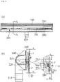
Figures 4A and 4B are views illustrating all of the components of the backwash suction device according to Embodiment 1 of the present invention in whichFigure 4A is a front view andFigure 4B is a cross-sectional view taken along line A-A inFigure 4A ; -
Figure 5 is an exploded perspective view illustrating all of the components of the backwash suction device of the fibrous filter according to Embodiment 1 of the present invention; -
Figure 6 is a perspective view illustrating components of a suction plate according to Embodiment 1 of the present invention which is shown by cutting a middle part in a longitudinal direction; -
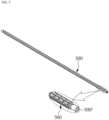
Figure 7 is a perspective view illustrating components of a pattern roller according to Embodiment 1 of the present invention; -
Figures 8A to 8C are perspective views of a modified example illustrating a part of the pattern roller according to Embodiment 1 of the present invention; -
Figure 9 is a cross-sectional view illustrating a backwash suction device according toEmbodiment 2 of the present invention; and -
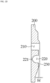
Figure 10 is a cross-sectional view illustrating components of a suction plate according toEmbodiment 2 of the present invention. - Hereinafter, an exemplary embodiment of the present invention will be described in detail with reference to the attached drawings. Before this, the terms used in the specification and the claims should not be limited to general or lexical meanings and should be interpreted as meanings and concepts coinciding with the technical concept of the present invention on the basis of a principle in which the inventor can appropriately define the concept of the terms to describe the invention in the best manner.
- Accordingly, since the embodiment disclosed in the specification and components shown in the drawings are merely one of most exemplary embodiments of the present invention and do not represent an entirety of the technical concept of the present invention, it should be understood that a variety of equivalents and modifications capable of substituting the embodiments and the components may be present at the time of filing of the present application.
- A backwash suction device of a fibrous filter according to Embodiment 1 of the present invention includes a
suction body 100 and asuction plate 200 in which aslit 210 is formed as shown inFigures 2 to 8C . - Particularly, the
suction plate 200 includes an incisedsurface 230 formed by cutting one surface of outer surfaces to a predetermined thickness W on the basis of theslit 210 so that a space between a disc-type filter D and thesuction plate 200 which increases by the thickness W may be secured in which fleeces F which have been backwashed in theslit 210 forms patterns on a fleece surface. - Here, a
room 220 is formed by cutting a part of a thickness of theslit 210 in the incisedsurface 230 and apattern roller 300 rotating in place is mounted in theroom 220 so that certain patterns are formed on the surface of the fleeces F between the suction plate and the disc-type filter D using an outer circumferential surface of thepattern roller 300 to increase a filtration area of the fleeces F accordingly. - Also, the
pattern roller 300 is formed to partially protrude outward from the incisedsurface 230 so as to easily and precisely form the patterns with respect to the surface of the fleeces F between the incisedsurface 230 and the disc-type filter D. - Meanwhile, a variety of shapes of patterns may be formed on the surface of the fleeces F on an outer circumference of the
pattern roller 300. Basically, spline-shaped uneven parts are formed lengthwise to form a spline cut with a predetermined length. In addition, as examples of patterns of thepattern roller 300, there are patterns in which annular protrusions are formed at predetermined intervals on the outer circumference of thepattern roller 300, patterns in which several strands of uneven parts are repeatedly formed like forming a spline in a longitudinal direction on the outer circumference of thepattern roller 300, and patterns in which lattice-shaped uneven parts are repeatedly formed. However, one type of patterns or a combination of two or more patterns may be formed. - Hereinafter, the above components will be described in detail with reference to the attached drawings. Here, reference symbol D refers to a disc-type filter used in a fibrous filter and reference symbol F refers to fleeces formed on the disc-type filter D to substantially filter out foreign matter stuck thereto.
- As shown in
Figures 3 to 5 , thesuction body 100 may be formed to have a container shape so as to discharge foreign matter suctioned in through thesuction plate 200 which will be described below and separated from the fleeces F outward from a septic tank. Accordingly, thesuction body 100 includes adrain hole 110 configured to discharge the foreign matter separated from the fleeces F outward from thesuction body 100. A pump or the like (not shown) is connected to thedrain hole 110 so as to drain a fluid with the foreign matter in thesuction body 100 outward from the septic tank. - The
suction body 100 is formed to have a length that is approximately a radius of the disc-type filter D so as to install thesuction body 100 according to the present invention in a radial direction of the disc-type filter D rotating in place in the septic tank. Accordingly, thesuction plate 200 mounted on thesuction body 100, which will be described below, is pressed against a surface of the disc-type filter D rotating in place so as to perform backwashing. - As shown in
Figures 3 to 6 , thesuction plate 200 closes an open inlet portion of thesuction body 100. Also, thesuction plate 200 is pressed against the surface of the disc-type filter D so as to allow the fleeces F forming the surface of the disc-type filter D to be suctioned in thesuction body 100 to be backwashed. Also, since thepattern roller 300 which will be described below is mounted on thesuction plate 200 so as to form predetermined patterns on the surface of the fleeces F which have been backwashed through theslit 210, a filtration area of the fibrous filter is increased and thus filtration efficiency is further increased. - As shown in
Figures 3 to 6 , thesuction plate 200 includes theslit 210, theroom 220, and the incisedsurface 230. - As shown in
Figures 3 to 6 , theslit 210 is formed lengthwise in one surface of thesuction plate 200 along a longitudinal direction. Here, since theslit 210 is formed with a length of approximately a radius of the disc-type filter D, theslits 210 are disposed to face each other in a radial direction so as to allow the fleeces F formed on the surface of the disc-type filter D to be suctioned in theslit 210 according to rotation of the disc-type filter D to perform a backwash of removing foreign matter stuck to the fleeces F. - In an exemplary embodiment of the present invention, although one
slit 210 is shown as being formed on thesuction plate 200, as an example, inFigures 3 to 6 , it should be easily seen by those skilled in the art that two or more slits may be formed. - As shown in
Figures 4A and 4B , the incisedsurface 230 is formed on an outer surface of thesuction plate 200, that is, a surface exposed outward when thesuction plate 200 is mounted on thesuction body 100. Here, the incisedsurface 230 is formed by cutting any one of both surfaces on the basis of theslit 210, and most preferably, a surface surpassed by the fleeces F which have been backwashed in theslit 210 with the predetermined thickness W. That is, since thesuction plate 200 is installed to be almost pressed against the disc-type filter D, the fleeces F before being backwashed in theslit 210 are laid flat due to a narrower pre-gap a between thesuction 200 and the disc-type filter D. Accordingly, in the present invention, since the incisedsurface 230 is formed to have the certain thickness W as described above, a post-gap b between the incisedsurface 230 and the disc-type filter D is wider than the pre-gap by as much as the thickness W of the incisedsurface 230. The post-gap b provides an adequate space for easily forming patterns when thepattern roller 300 which will be described below forms the patterns on the surface of the fleeces F. - As shown in
Figures 3 to 6 , theroom 220 is formed by cutting a part of the thickness of theslit 210 in which the incisedsurface 230 is formed. Here, thepattern roller 300 which will be described below is mounted in theroom 220 and is formed to have a size so as to naturally rotate in place without interference between thepattern roller 300 and other components while thepattern roller 300 rotates in place and forms the patterns on the surface of the fleeces F. - In an exemplary embodiment of the present invention, as shown in
Figures 4A to 6 , theroom 220 is formed to be parallel to theslit 210 so that the patterns may be formed with respect to the fleeces F withdrawn from theslit 210 after being backwashed. - As shown in
Figures 3 to 5 , thepattern roller 300 is mounted in theroom 220 to rotate in place on the basis of a shaft 300'. Here, since thepattern roller 300 includes predetermined patterns on the outer circumference thereof, the patterns are formed on the surface of the fleeces F of the disc-type filter D rotating while being pressed against thepattern roller 300 and a surface area of the surface of the fleeces F, that is, the filtration area, is increased accordingly so that filtration efficiency of the disc-type filter D may be increased. Here, the surface of the fleeces F refers to a surface formed of the fleeces F which are backwashed while being laid aside between thesuction plate 200 and the disc-type filter D and passing through theslit 210 and then collapsing as one flat surface while moving into a space between thesuction plate 200 and the disc-type filter D. - The outer circumference of the
pattern roller 300 is configured to form a variety of shapes of patterns on the surface of the fleeces F as shown inFigures 7 to 8 . For example, the patterns include spline-shaped uneven parts as shown inFigure 7 while the patterns may be formed so that splines are cut with a predetermined length or the patterns may be formed as a vertically lengthwise groove using annular protrusions formed on the outer circumference of thepattern roller 300 at predetermined intervals as shown inFigure 8A . Also, several strands of uneven parts may be repeatedly formed like forming splines on the outer circumference of thepattern roller 300 in a longitudinal direction as shown inFigure 8B or lattice-shaped uneven parts may be repeatedly formed as shown inFigure 8C . However, it may be easily seen by those skilled in the art that one of these patterns may be used or a combination of two or more of the patterns may be used. Also, a variety of additional patterns may be formed on the outer circumference of thepattern roller 300. - Meanwhile, in an exemplary embodiment of the present invention, as shown in
Figure 4A , thepattern roller 300 may be mounted in theroom 220 to partially protrude outward further than the incisedsurface 230. This is to further increase the filtration area by forming the predetermined patterns to be deep in the surface of the fleeces F which are backwashed in theslit 210 and then surpassing the incisedsurface 230 using thepattern roller 300 protruding further than the incisedsurface 230. - In the present invention, since the pattern roller rotating in place is mounted on the incised surface formed in the surface of the suction plate surpassing the slit, the fleeces which are backwashed in the slit surpasses the pattern roller, and the predetermined patterns are formed thereon between the incised surface and the disc-type filter so that the filtration area of the fibrous filter is increased accordingly using the patterns formed on the fleece surface as the fleeces pass the suction plate and thus a filtration effect is increased.
- Also, since the filtration area is increased, suspended matter may be further removed accordingly. In another aspect, in comparison to related arts, a volume of a filter is reduced and a site necessary for installation is made smaller.
- As shown in
Figures 9 and10 , a backwash suction device of a fibrous filter according toEmbodiment 2 of the present invention has the same components as in Embodiment 1 but has a slight difference in components of theroom 220. Hereupon, a detailed description on the same components as those of Embodiment 1 will be omitted and only differences will be described herein. - In
Embodiment 2, as shown inFigures 9 and10 , like Embodiment 1, theroom 220 in which thepattern roller 300 is mounted is formed in the incisedsurface 230 formed in any one side of thesuction plate 200 exposed outward on the basis of theslit 210. Here, theroom 220 is formed to be spaced at a predetermined interval apart from theslit 210 and anauxiliary slit 221 is formed in theroom 220 to pass therethrough to communicate with an inside of thesuction body 100. - Like Embodiment 1, the room configured as described above also allows the patterns to be formed on the fleece surface backwashed in the slit and hung across a part of the incised surface between the slit and the room using the pattern roller mounted in the room so as to increase the filtration area of the disc-type filter.
- A backwash suction device of a fibrous filter according to the present invention provides the following effects. (1) Since an incised surface is formed by cutting one side of an outer surface of a suction plate on the basis of a slit to a predetermined thickness and a pattern roller is installed in a room, which is provided at a thickness part of the slit in which the incised surface is formed, to rotate in place, patterns are formed on a surface of fleeces which are backwashed while passing through the slit and then pushed between the suction plate and a disc-type filter using the pattern roller so that a filtration area of a fleece surface may be increased and consequentially filtration efficiency of a fibrous filter may be increased.
- Also, since the filtration area is increased, floating matter may be further removed accordingly. In another aspect, in comparison to related arts, a volume of a filter is reduced and a site necessary for installation is reduced.
- (2) Here, since the room is formed at a location spaced at a predetermined distance apart from the slit in the incised surface and an auxiliary slit is formed to pass through a bottom of the room, backwash may be performed using the room, and the patterns may be formed on the fleece surface of the disc-type filter using the pattern roller mounted in the room so that the filtration area may be increased and thus filtration efficiency of the fibrous filter may be further increased.
- (3) Here, since the incised surface provides an adequate space between the suction plate and the disc-type filter so as not to allow the patterns formed on the fleece surface pressed against the disc-type filter to be pushed again, the patterns formed on the fleece surface using the pattern roller may remain in shape so as to increase a filtration area.
- (4) Accordingly, since the pattern roller mounted in the room is mounted to protrude outward by a certain thickness further than the incised surface, desired patterns may be easily formed on the fleece surface using a protruding part of the pattern roller so as to increase filtration efficiency of the fibrous filter.
- (5) Meanwhile, anything capable of increasing a filtration area by forming certain patterns on the fleece surface of the disc-type filter may be used on an outer surface of the pattern roller. As the patterns, for example, there are patterns including splines formed to be lengthwise in a longitudinal direction thereof while each spline is cut to a certain length, patterns including several annular protrusions formed at predetermined intervals on an outer circumference of the pattern roller, spline-shaped patterns formed to be lengthwise in a longitudinal direction on an outer circumferential surface, and lattice-shaped patterns including repeated uneven parts. Also, one type of patterns may be used or a combination of two or more types of patterns may be used as the patterns.
Claims (3)
- A backwash suction device of a fibrous filter, comprising:- a suction body (100) having a container shape and including a drain hole (110) to discharge content from inside the suction body (100) outward; and- a suction plate (200) mounted in the suction body (100) to close an inlet part thereof and including a slit (210) formed to perform backwash,wherein an incised surface (230) is formed in the suction plate (200) by cutting one side of a surface exposed outward on the basis of the slit (210) to a predetermined thickness (W), a room (220) is provided by cutting a part of a thickness of the slit (210) in which the incised surface (230) is formed, and a pattern roller (300) is mounted in the room (220) to rotate in place while being partially exposed and protruding outward from the incised surface (230) so as to form patterns on a surface of fleeces F which have passed through the slit (210).
- A backwash suction device of a fibrous filter, comprising:- a suction body (100) having a container shape and including a drain hole (110) to discharge content from inside the suction body (100) outward; and- a suction plate (200) mounted in the suction body (100) to close an inlet part thereof and including a slit (210) formed to perform backwash,wherein an incised surface (230) is formed in the suction plate (200) by cutting one side of a surface exposed outward on the basis of the slit (210) to a predetermined thickness (W), a room (220) is provided in the incised surface (230) while being spaced at a predetermined distance apart from the slit (210), an auxiliary slit (221) is formed in the room (220) to pass therethrough to communicate with the suction body (100), and a pattern roller (300) is mounted in the room (220) to rotate in place while being partially exposed and protruding outward from the incised surface (230) so as to form patterns on a surface of fleeces F which have passed through the slit (210).
- The backwash suction device of a fibrous filter according to any one of claims 1 and 2, wherein an outer surface of the pattern roller (300) comprises at least one of:- patterns including splines formed to be lengthwise in a longitudinal direction of the pattern roller (300) while each spline is cut to a certain length;- patterns including several annular protrusions formed at predetermined intervals on an outer circumference of the pattern roller (300);- spline-shaped patterns formed to be lengthwise in the longitudinal direction of the pattern roller (300); and- lattice-shaped patterns including repeated uneven parts.
Applications Claiming Priority (1)
| Application Number | Priority Date | Filing Date | Title |
|---|---|---|---|
| KR1020210098846A KR102404899B1 (en) | 2021-07-27 | 2021-07-27 | Back wash device for fabric filtration apparatus |
Publications (3)
| Publication Number | Publication Date |
|---|---|
| EP4124373A1 true EP4124373A1 (en) | 2023-02-01 |
| EP4124373B1 EP4124373B1 (en) | 2025-01-01 |
| EP4124373C0 EP4124373C0 (en) | 2025-01-01 |
Family
ID=80080123
Family Applications (1)
| Application Number | Title | Priority Date | Filing Date |
|---|---|---|---|
| EP22159712.3A Active EP4124373B1 (en) | 2021-07-27 | 2022-03-02 | Backwash suction device of fibrous filter |
Country Status (10)
| Country | Link |
|---|---|
| US (1) | US11724218B2 (en) |
| EP (1) | EP4124373B1 (en) |
| JP (1) | JP7318991B2 (en) |
| KR (1) | KR102404899B1 (en) |
| CN (1) | CN118019569A (en) |
| AU (1) | AU2021286408B2 (en) |
| CA (1) | CA3144186C (en) |
| ES (1) | ES3014541T3 (en) |
| GB (1) | GB2609272B (en) |
| WO (1) | WO2023008613A1 (en) |
Families Citing this family (5)
| Publication number | Priority date | Publication date | Assignee | Title |
|---|---|---|---|---|
| KR102264455B1 (en) * | 2020-08-03 | 2021-06-11 | 문연우 | Fiber Discfilter comprising groove forming means on the surface of filter cloths |
| US12377372B2 (en) * | 2021-06-08 | 2025-08-05 | Greatpyr Resources Llc | Apparatus, systems, and processes employing wet/dry suction filter with chicaned suction head |
| KR102404899B1 (en) * | 2021-07-27 | 2022-06-07 | 주식회사 그레넥스 | Back wash device for fabric filtration apparatus |
| DE102022118497A1 (en) * | 2022-07-25 | 2024-01-25 | Mecana Umwelttechnik Gmbh | Device for cleaning and/or suctioning pile fibers for pile filtration |
| KR102746375B1 (en) | 2023-08-28 | 2024-12-24 | 주식회사 그레넥스 | Back wash device for a fabric filtration apparatus and the fabric filtration apparatus itself |
Citations (7)
| Publication number | Priority date | Publication date | Assignee | Title |
|---|---|---|---|---|
| US20090178976A1 (en) * | 2006-10-20 | 2009-07-16 | Jay Stevens | Filtering device for liquid filtration |
| US20130048553A1 (en) * | 2011-08-31 | 2013-02-28 | Younglong KUK | Suction apparatus for fabric filter and filtering device for liquid filtration using the same |
| US20130105415A1 (en) * | 2011-10-28 | 2013-05-02 | Yongming Xia | Methods and apparatus for treating water and wastewater employing a cloth disk filter |
| KR101791863B1 (en) | 2017-04-25 | 2017-11-01 | 주식회사 그레넥스 | Back-washing suction apparatus for fabric filtration apparatus |
| KR20180020500A (en) | 2016-08-18 | 2018-02-28 | 주식회사 그레넥스 | Suction box for back-washing apparatus of fabric filtration apparatus |
| US10195549B1 (en) * | 2017-11-21 | 2019-02-05 | Aqua-Aerobic Systems, Inc. | Backwash shoe method and apparatus that increases effective surface area of cloth filter media |
| KR102183820B1 (en) | 2020-03-10 | 2020-11-30 | 주식회사 그레넥스 | Back wash device for fabric filtration apparatus |
Family Cites Families (22)
| Publication number | Priority date | Publication date | Assignee | Title |
|---|---|---|---|---|
| US2932402A (en) * | 1954-11-15 | 1960-04-12 | Denver Equip Co | Disc type filter |
| US3945924A (en) * | 1971-02-24 | 1976-03-23 | Peterson Filters & Engineering Company | Apparatus for impact discharge of filter cake from a moving filter medium and for compacting filter cake thereon |
| US4166034A (en) * | 1978-05-08 | 1979-08-28 | Bodine Albert G | Method and apparatus for sonically dehydrating precipitate |
| FI76705C (en) * | 1987-04-16 | 1988-12-12 | Valmet Paper Machinery Inc | FOERFARANDE FOER RENGOERING AV FILTERPLATTOR FOER SUGTORKANORDNING. |
| DE19828171A1 (en) * | 1998-06-24 | 1999-12-30 | Mecana Umwelttechnik Ag Reiche | Carpet-like filter unit for waste water, in which flow is directed towards deep pile to trap particles |
| JP3431067B2 (en) * | 1999-02-25 | 2003-07-28 | 株式会社ベリタス | Suspended matter filtration processing equipment |
| JP2002345699A (en) * | 2001-05-28 | 2002-12-03 | Matsushita Electric Ind Co Ltd | Vacuum cleaner suction tool and vacuum cleaner using the same |
| KR20020040550A (en) * | 2001-10-26 | 2002-05-30 | 정석표 | Cylindrical cartridge filter with improved filtering capacity |
| JP4009514B2 (en) * | 2002-09-27 | 2007-11-14 | 倉敷繊維加工株式会社 | Biodegradable air cleaning filter |
| US7754041B2 (en) * | 2006-07-31 | 2010-07-13 | 3M Innovative Properties Company | Pleated filter with bimodal monolayer monocomponent media |
| CN101674872B (en) * | 2007-05-28 | 2013-01-09 | 花王株式会社 | Anti-fouling filters for ventilation fans or range hoods |
| JP2010131580A (en) * | 2008-10-30 | 2010-06-17 | Duskin Co Ltd | Filter, exhauster using the same, manufacturing method of filter and filter manufacturing device |
| CN102470296B (en) * | 2009-07-31 | 2014-10-29 | 金君守 | Zigzag-type fiber filter and filtering apparatus using same |
| MY183762A (en) * | 2010-10-14 | 2021-03-11 | Fairtech Investment Ltd | Nonwoven fabric, manufacturing method thereof and filters formed by it |
| KR101299150B1 (en) * | 2013-02-28 | 2013-08-26 | (주)한강이엔지 | Method for helical tubular depth filter element |
| CN103316540B (en) * | 2013-06-21 | 2016-01-20 | 北京市神力达环保科技有限公司 | A kind of fibrous filter and preparation method thereof and use the filter of this fibrous filter |
| US9314718B2 (en) * | 2013-11-10 | 2016-04-19 | Yamit Filtration & Water Treatment Ltd | Backwash arrangement for cleaning a cylindrical filter screen |
| CN106550595B (en) * | 2014-08-31 | 2020-03-31 | 过滤艺术有限公司 | Filter with stacked filter discs |
| WO2017092777A1 (en) * | 2015-12-03 | 2017-06-08 | Kronos International, Inc. | Method and device for improved solid-liquid filtration of filter cakes |
| CN105854386B (en) * | 2016-05-23 | 2017-11-10 | 三明市缘福生物质科技有限公司 | A kind of sewage-treatment plant |
| KR102264455B1 (en) * | 2020-08-03 | 2021-06-11 | 문연우 | Fiber Discfilter comprising groove forming means on the surface of filter cloths |
| KR102404899B1 (en) * | 2021-07-27 | 2022-06-07 | 주식회사 그레넥스 | Back wash device for fabric filtration apparatus |
-
2021
- 2021-07-27 KR KR1020210098846A patent/KR102404899B1/en active Active
- 2021-07-29 WO PCT/KR2021/009869 patent/WO2023008613A1/en not_active Ceased
- 2021-07-29 CN CN202180102201.0A patent/CN118019569A/en active Pending
- 2021-12-15 GB GB2118193.8A patent/GB2609272B/en active Active
- 2021-12-17 AU AU2021286408A patent/AU2021286408B2/en active Active
- 2021-12-29 CA CA3144186A patent/CA3144186C/en active Active
-
2022
- 2022-01-05 JP JP2022000504A patent/JP7318991B2/en active Active
- 2022-01-14 US US17/575,692 patent/US11724218B2/en active Active
- 2022-03-02 ES ES22159712T patent/ES3014541T3/en active Active
- 2022-03-02 EP EP22159712.3A patent/EP4124373B1/en active Active
Patent Citations (7)
| Publication number | Priority date | Publication date | Assignee | Title |
|---|---|---|---|---|
| US20090178976A1 (en) * | 2006-10-20 | 2009-07-16 | Jay Stevens | Filtering device for liquid filtration |
| US20130048553A1 (en) * | 2011-08-31 | 2013-02-28 | Younglong KUK | Suction apparatus for fabric filter and filtering device for liquid filtration using the same |
| US20130105415A1 (en) * | 2011-10-28 | 2013-05-02 | Yongming Xia | Methods and apparatus for treating water and wastewater employing a cloth disk filter |
| KR20180020500A (en) | 2016-08-18 | 2018-02-28 | 주식회사 그레넥스 | Suction box for back-washing apparatus of fabric filtration apparatus |
| KR101791863B1 (en) | 2017-04-25 | 2017-11-01 | 주식회사 그레넥스 | Back-washing suction apparatus for fabric filtration apparatus |
| US10195549B1 (en) * | 2017-11-21 | 2019-02-05 | Aqua-Aerobic Systems, Inc. | Backwash shoe method and apparatus that increases effective surface area of cloth filter media |
| KR102183820B1 (en) | 2020-03-10 | 2020-11-30 | 주식회사 그레넥스 | Back wash device for fabric filtration apparatus |
Also Published As
| Publication number | Publication date |
|---|---|
| EP4124373B1 (en) | 2025-01-01 |
| KR102404899B1 (en) | 2022-06-07 |
| CN118019569A (en) | 2024-05-10 |
| GB202118193D0 (en) | 2022-01-26 |
| US11724218B2 (en) | 2023-08-15 |
| WO2023008613A1 (en) | 2023-02-02 |
| ES3014541T3 (en) | 2025-04-23 |
| JP2023018627A (en) | 2023-02-08 |
| US20230032256A1 (en) | 2023-02-02 |
| AU2021286408B2 (en) | 2023-11-23 |
| CA3144186A1 (en) | 2023-01-27 |
| GB2609272B (en) | 2026-03-11 |
| GB2609272A (en) | 2023-02-01 |
| EP4124373C0 (en) | 2025-01-01 |
| CA3144186C (en) | 2023-08-29 |
| AU2021286408A1 (en) | 2023-02-16 |
| JP7318991B2 (en) | 2023-08-01 |
Similar Documents
| Publication | Publication Date | Title |
|---|---|---|
| EP4124373A1 (en) | Backwash suction device of fibrous filter | |
| KR102476876B1 (en) | Fiber Discfilter comprising groove forming means on the surface of filter cloths | |
| US6294098B1 (en) | High efficiency backwash shoe | |
| CN102430339B (en) | Self-cleaning filtering membrane device | |
| KR102183820B1 (en) | Back wash device for fabric filtration apparatus | |
| CA2787795C (en) | Suction apparatus for fabric filter and filtering device for liquid filtration using the same | |
| KR101829378B1 (en) | Filter disk filter-type filtration device with uniform suction cleaning function | |
| CN114245849B (en) | Scraping elements for the impeller inlet edge of sewage pumps | |
| US5389256A (en) | Filter apparatus for machine tool coolant | |
| EP0938359B1 (en) | Filter sector for a rotating filter disc | |
| CN107126741B (en) | Filtering equipment | |
| CN109789348B (en) | Filter element | |
| KR102048894B1 (en) | Apparatus for filtering waste water | |
| KR20210106646A (en) | Cloth media disc filtration apparatus | |
| KR20030004964A (en) | Cylindrical screen | |
| KR100828314B1 (en) | Foreign Material Filter | |
| KR20210106652A (en) | Cloth media disc filtration apparatus | |
| KR20210106649A (en) | Cloth media disc filtration apparatus | |
| JP2022044258A (en) | Water pouring well and ground water recharge device | |
| CN202410520U (en) | Filtering membrane self-cleaning device | |
| CN119075428A (en) | Vertical filter device | |
| KR0117797Y1 (en) | Fuel Purifier of Oil Combustor | |
| US20170007947A1 (en) | Micronic automatic filter | |
| KR19990020603U (en) | Niche retention zone for foreign matter sorting device of Haitai Woncho | |
| KR20150070452A (en) | Filtering Apparatus for Engine |
Legal Events
| Date | Code | Title | Description |
|---|---|---|---|
| PUAI | Public reference made under article 153(3) epc to a published international application that has entered the european phase |
Free format text: ORIGINAL CODE: 0009012 |
|
| STAA | Information on the status of an ep patent application or granted ep patent |
Free format text: STATUS: THE APPLICATION HAS BEEN PUBLISHED |
|
| AK | Designated contracting states |
Kind code of ref document: A1 Designated state(s): AL AT BE BG CH CY CZ DE DK EE ES FI FR GB GR HR HU IE IS IT LI LT LU LV MC MK MT NL NO PL PT RO RS SE SI SK SM TR |
|
| STAA | Information on the status of an ep patent application or granted ep patent |
Free format text: STATUS: REQUEST FOR EXAMINATION WAS MADE |
|
| 17P | Request for examination filed |
Effective date: 20230724 |
|
| RBV | Designated contracting states (corrected) |
Designated state(s): AL AT BE BG CH CY CZ DE DK EE ES FI FR GB GR HR HU IE IS IT LI LT LU LV MC MK MT NL NO PL PT RO RS SE SI SK SM TR |
|
| GRAP | Despatch of communication of intention to grant a patent |
Free format text: ORIGINAL CODE: EPIDOSNIGR1 |
|
| STAA | Information on the status of an ep patent application or granted ep patent |
Free format text: STATUS: GRANT OF PATENT IS INTENDED |
|
| INTG | Intention to grant announced |
Effective date: 20240516 |
|
| GRAS | Grant fee paid |
Free format text: ORIGINAL CODE: EPIDOSNIGR3 |
|
| GRAJ | Information related to disapproval of communication of intention to grant by the applicant or resumption of examination proceedings by the epo deleted |
Free format text: ORIGINAL CODE: EPIDOSDIGR1 |
|
| GRAL | Information related to payment of fee for publishing/printing deleted |
Free format text: ORIGINAL CODE: EPIDOSDIGR3 |
|
| STAA | Information on the status of an ep patent application or granted ep patent |
Free format text: STATUS: REQUEST FOR EXAMINATION WAS MADE |
|
| GRAP | Despatch of communication of intention to grant a patent |
Free format text: ORIGINAL CODE: EPIDOSNIGR1 |
|
| STAA | Information on the status of an ep patent application or granted ep patent |
Free format text: STATUS: GRANT OF PATENT IS INTENDED |
|
| INTC | Intention to grant announced (deleted) | ||
| INTG | Intention to grant announced |
Effective date: 20240904 |
|
| GRAA | (expected) grant |
Free format text: ORIGINAL CODE: 0009210 |
|
| STAA | Information on the status of an ep patent application or granted ep patent |
Free format text: STATUS: THE PATENT HAS BEEN GRANTED |
|
| AK | Designated contracting states |
Kind code of ref document: B1 Designated state(s): AL AT BE BG CH CY CZ DE DK EE ES FI FR GB GR HR HU IE IS IT LI LT LU LV MC MK MT NL NO PL PT RO RS SE SI SK SM TR |
|
| REG | Reference to a national code |
Ref country code: GB Ref legal event code: FG4D |
|
| REG | Reference to a national code |
Ref country code: CH Ref legal event code: EP |
|
| REG | Reference to a national code |
Ref country code: DE Ref legal event code: R096 Ref document number: 602022009214 Country of ref document: DE |
|
| REG | Reference to a national code |
Ref country code: IE Ref legal event code: FG4D |
|
| U01 | Request for unitary effect filed |
Effective date: 20250122 |
|
| U07 | Unitary effect registered |
Designated state(s): AT BE BG DE DK EE FI FR IT LT LU LV MT NL PT RO SE SI Effective date: 20250128 |
|
| REG | Reference to a national code |
Ref country code: ES Ref legal event code: FG2A Ref document number: 3014541 Country of ref document: ES Kind code of ref document: T3 Effective date: 20250423 |
|
| U20 | Renewal fee for the european patent with unitary effect paid |
Year of fee payment: 4 Effective date: 20250331 |
|
| PG25 | Lapsed in a contracting state [announced via postgrant information from national office to epo] |
Ref country code: PL Free format text: LAPSE BECAUSE OF FAILURE TO SUBMIT A TRANSLATION OF THE DESCRIPTION OR TO PAY THE FEE WITHIN THE PRESCRIBED TIME-LIMIT Effective date: 20250101 |
|
| PGFP | Annual fee paid to national office [announced via postgrant information from national office to epo] |
Ref country code: ES Payment date: 20250401 Year of fee payment: 4 |
|
| PG25 | Lapsed in a contracting state [announced via postgrant information from national office to epo] |
Ref country code: NO Free format text: LAPSE BECAUSE OF FAILURE TO SUBMIT A TRANSLATION OF THE DESCRIPTION OR TO PAY THE FEE WITHIN THE PRESCRIBED TIME-LIMIT Effective date: 20250401 Ref country code: IS Free format text: LAPSE BECAUSE OF FAILURE TO SUBMIT A TRANSLATION OF THE DESCRIPTION OR TO PAY THE FEE WITHIN THE PRESCRIBED TIME-LIMIT Effective date: 20250501 |
|
| PG25 | Lapsed in a contracting state [announced via postgrant information from national office to epo] |
Ref country code: HR Free format text: LAPSE BECAUSE OF FAILURE TO SUBMIT A TRANSLATION OF THE DESCRIPTION OR TO PAY THE FEE WITHIN THE PRESCRIBED TIME-LIMIT Effective date: 20250101 |
|
| PG25 | Lapsed in a contracting state [announced via postgrant information from national office to epo] |
Ref country code: GR Free format text: LAPSE BECAUSE OF FAILURE TO SUBMIT A TRANSLATION OF THE DESCRIPTION OR TO PAY THE FEE WITHIN THE PRESCRIBED TIME-LIMIT Effective date: 20250402 |
|
| PGFP | Annual fee paid to national office [announced via postgrant information from national office to epo] |
Ref country code: CH Payment date: 20250401 Year of fee payment: 4 |
|
| PG25 | Lapsed in a contracting state [announced via postgrant information from national office to epo] |
Ref country code: SM Free format text: LAPSE BECAUSE OF FAILURE TO SUBMIT A TRANSLATION OF THE DESCRIPTION OR TO PAY THE FEE WITHIN THE PRESCRIBED TIME-LIMIT Effective date: 20250101 |
|
| PG25 | Lapsed in a contracting state [announced via postgrant information from national office to epo] |
Ref country code: MC Free format text: LAPSE BECAUSE OF FAILURE TO SUBMIT A TRANSLATION OF THE DESCRIPTION OR TO PAY THE FEE WITHIN THE PRESCRIBED TIME-LIMIT Effective date: 20250101 |
|
| PG25 | Lapsed in a contracting state [announced via postgrant information from national office to epo] |
Ref country code: SK Free format text: LAPSE BECAUSE OF FAILURE TO SUBMIT A TRANSLATION OF THE DESCRIPTION OR TO PAY THE FEE WITHIN THE PRESCRIBED TIME-LIMIT Effective date: 20250101 |
|
| PLBE | No opposition filed within time limit |
Free format text: ORIGINAL CODE: 0009261 |
|
| STAA | Information on the status of an ep patent application or granted ep patent |
Free format text: STATUS: NO OPPOSITION FILED WITHIN TIME LIMIT |
|
| REG | Reference to a national code |
Ref country code: CH Ref legal event code: L10 Free format text: ST27 STATUS EVENT CODE: U-0-0-L10-L00 (AS PROVIDED BY THE NATIONAL OFFICE) Effective date: 20251112 |
|
| 26N | No opposition filed |
Effective date: 20251002 |
|
| REG | Reference to a national code |
Ref country code: CH Ref legal event code: U11 Free format text: ST27 STATUS EVENT CODE: U-0-0-U10-U11 (AS PROVIDED BY THE NATIONAL OFFICE) Effective date: 20260401 |
|
| PGFP | Annual fee paid to national office [announced via postgrant information from national office to epo] |
Ref country code: IE Payment date: 20260327 Year of fee payment: 5 |
|
| PGFP | Annual fee paid to national office [announced via postgrant information from national office to epo] |
Ref country code: TR Payment date: 20260309 Year of fee payment: 5 |
|
| PGFP | Annual fee paid to national office [announced via postgrant information from national office to epo] |
Ref country code: CZ Payment date: 20260303 Year of fee payment: 5 |
|
| U20 | Renewal fee for the european patent with unitary effect paid |
Year of fee payment: 5 Effective date: 20260324 |