EP4124067A1 - Sound output device, sound image adjustment method and volume adjustment method - Google Patents
Sound output device, sound image adjustment method and volume adjustment method Download PDFInfo
- Publication number
- EP4124067A1 EP4124067A1 EP20933329.3A EP20933329A EP4124067A1 EP 4124067 A1 EP4124067 A1 EP 4124067A1 EP 20933329 A EP20933329 A EP 20933329A EP 4124067 A1 EP4124067 A1 EP 4124067A1
- Authority
- EP
- European Patent Office
- Prior art keywords
- speaker
- sound
- sound wave
- volume
- mechanical structure
- Prior art date
- Legal status (The legal status is an assumption and is not a legal conclusion. Google has not performed a legal analysis and makes no representation as to the accuracy of the status listed.)
- Granted
Links
Images


Classifications
-
- H—ELECTRICITY
- H04—ELECTRIC COMMUNICATION TECHNIQUE
- H04R—LOUDSPEAKERS, MICROPHONES, GRAMOPHONE PICK-UPS OR LIKE ACOUSTIC ELECTROMECHANICAL TRANSDUCERS; ELECTRIC HEARING AIDS; PUBLIC ADDRESS SYSTEMS
- H04R5/00—Stereophonic arrangements
- H04R5/033—Headphones for stereophonic communication
-
- H—ELECTRICITY
- H04—ELECTRIC COMMUNICATION TECHNIQUE
- H04R—LOUDSPEAKERS, MICROPHONES, GRAMOPHONE PICK-UPS OR LIKE ACOUSTIC ELECTROMECHANICAL TRANSDUCERS; ELECTRIC HEARING AIDS; PUBLIC ADDRESS SYSTEMS
- H04R3/00—Circuits for transducers
- H04R3/12—Circuits for transducers for distributing signals to two or more loudspeakers
-
- H—ELECTRICITY
- H04—ELECTRIC COMMUNICATION TECHNIQUE
- H04R—LOUDSPEAKERS, MICROPHONES, GRAMOPHONE PICK-UPS OR LIKE ACOUSTIC ELECTROMECHANICAL TRANSDUCERS; ELECTRIC HEARING AIDS; PUBLIC ADDRESS SYSTEMS
- H04R1/00—Details of transducers, loudspeakers or microphones
- H04R1/10—Earpieces; Attachments therefor ; Earphones; Monophonic headphones
- H04R1/1058—Manufacture or assembly
-
- H—ELECTRICITY
- H04—ELECTRIC COMMUNICATION TECHNIQUE
- H04R—LOUDSPEAKERS, MICROPHONES, GRAMOPHONE PICK-UPS OR LIKE ACOUSTIC ELECTROMECHANICAL TRANSDUCERS; ELECTRIC HEARING AIDS; PUBLIC ADDRESS SYSTEMS
- H04R25/00—Electric hearing aids
- H04R25/60—Mounting or interconnection of hearing aid parts, e.g. inside tips, housings or to ossicles
- H04R25/604—Mounting or interconnection of hearing aid parts, e.g. inside tips, housings or to ossicles of acoustic or vibrational transducers
- H04R25/606—Mounting or interconnection of hearing aid parts, e.g. inside tips, housings or to ossicles of acoustic or vibrational transducers acting directly on the eardrum, the ossicles or the skull, e.g. mastoid, tooth, maxillary or mandibular bone, or mechanically stimulating the cochlea, e.g. at the oval window
-
- H—ELECTRICITY
- H04—ELECTRIC COMMUNICATION TECHNIQUE
- H04R—LOUDSPEAKERS, MICROPHONES, GRAMOPHONE PICK-UPS OR LIKE ACOUSTIC ELECTROMECHANICAL TRANSDUCERS; ELECTRIC HEARING AIDS; PUBLIC ADDRESS SYSTEMS
- H04R3/00—Circuits for transducers
- H04R3/04—Circuits for transducers for correcting frequency response
-
- H—ELECTRICITY
- H04—ELECTRIC COMMUNICATION TECHNIQUE
- H04R—LOUDSPEAKERS, MICROPHONES, GRAMOPHONE PICK-UPS OR LIKE ACOUSTIC ELECTROMECHANICAL TRANSDUCERS; ELECTRIC HEARING AIDS; PUBLIC ADDRESS SYSTEMS
- H04R5/00—Stereophonic arrangements
- H04R5/04—Circuit arrangements, e.g. for selective connection of amplifier inputs/outputs to loudspeakers, for loudspeaker detection, or for adaptation of settings to personal preferences or hearing impairments
-
- H—ELECTRICITY
- H04—ELECTRIC COMMUNICATION TECHNIQUE
- H04R—LOUDSPEAKERS, MICROPHONES, GRAMOPHONE PICK-UPS OR LIKE ACOUSTIC ELECTROMECHANICAL TRANSDUCERS; ELECTRIC HEARING AIDS; PUBLIC ADDRESS SYSTEMS
- H04R9/00—Transducers of moving-coil, moving-strip, or moving-wire type
- H04R9/02—Details
- H04R9/04—Construction, mounting, or centering of coil
- H04R9/046—Construction
-
- H—ELECTRICITY
- H04—ELECTRIC COMMUNICATION TECHNIQUE
- H04R—LOUDSPEAKERS, MICROPHONES, GRAMOPHONE PICK-UPS OR LIKE ACOUSTIC ELECTROMECHANICAL TRANSDUCERS; ELECTRIC HEARING AIDS; PUBLIC ADDRESS SYSTEMS
- H04R1/00—Details of transducers, loudspeakers or microphones
- H04R1/20—Arrangements for obtaining desired frequency or directional characteristics
- H04R1/32—Arrangements for obtaining desired frequency or directional characteristics for obtaining desired directional characteristic only
- H04R1/40—Arrangements for obtaining desired frequency or directional characteristics for obtaining desired directional characteristic only by combining a number of identical transducers
- H04R1/403—Arrangements for obtaining desired frequency or directional characteristics for obtaining desired directional characteristic only by combining a number of identical transducers loud-speakers
-
- H—ELECTRICITY
- H04—ELECTRIC COMMUNICATION TECHNIQUE
- H04R—LOUDSPEAKERS, MICROPHONES, GRAMOPHONE PICK-UPS OR LIKE ACOUSTIC ELECTROMECHANICAL TRANSDUCERS; ELECTRIC HEARING AIDS; PUBLIC ADDRESS SYSTEMS
- H04R2460/00—Details of hearing devices, i.e. of ear- or headphones covered by H04R1/10 or H04R5/033 but not provided for in any of their subgroups, or of hearing aids covered by H04R25/00 but not provided for in any of its subgroups
- H04R2460/13—Hearing devices using bone conduction transducers
-
- H—ELECTRICITY
- H04—ELECTRIC COMMUNICATION TECHNIQUE
- H04S—STEREOPHONIC SYSTEMS
- H04S2400/00—Details of stereophonic systems covered by H04S but not provided for in its groups
- H04S2400/13—Aspects of volume control, not necessarily automatic, in stereophonic sound systems
Definitions
- the present disclosure relates to the acoustic field, and in particular, to a sound output device, a sensory sound source adjustment method, and a volume adjustment method.
- an amplitude of a bone-conduction speaker is in positive correlation with sound volume generated by the bone-conduction speaker.
- Mass of a housing of the bone-conduction speaker has an obvious impact on the amplitude of the bone-conduction speaker, and further affects the sound volume generated by the speaker.
- additional functional modules such as a headset microphone (for example, a microphone with an extension rod) and buttons sometimes need to be arranged on only one side of a bone-conduction speaker and not on the other side. The arrangement of the buttons on the bone-conduction speaker changes mass distribution of the bone-conduction speaker, and therefore affects sound volume generated by the speaker.
- the functional modules such as the headset microphone or buttons only need to be arranged on one side and are not arranged on the other side, thereby causing volume difference between speakers on the two sides (a speaker volume in one ear is high but a speaker volume in the other ear is low), resulting in a sensory sound source shift. If there is a great difference in volume between a speaker on the left side and a speaker on the right side, long-term use of the earphone may cause hearing impairments. Therefore, a sensory sound source needs to be adjusted, so that the sensory sound source is centered, or volume of the speakers of the earphone on both sides needs to be adjusted, so that the volume of the speakers on both sides is identical.
- this application discloses a sound output device, including: a signal processing circuit to generate, during operation, a first electrical signal and a second electrical signal based on target sound information; a first speaker, electrically connected to the signal processing circuit to receive, during operation, the first electrical signal from the signal processing circuit and convert the first electrical signal into a first sound wave; and a second speaker, electrically connected to the signal processing circuit to receive, during operation, the second electrical signal from the signal processing circuit and convert the second electrical signal into a second sound wave, where the sound output device converts the target sound information into the first sound wave in a first duration and further converts the target sound information into the second sound wave in a second duration, and the first duration is shorter than the second duration by a time difference.
- volume of a sound wave output by the first speaker is lower than volume of a sound wave output by the second speaker.
- a difference between the volume of the first sound wave and the volume of the second sound wave is not greater than 3 dB.
- the first speaker generates the first sound wave by exciting a first mechanical structure; and the second speaker generates the second sound wave by exciting a second mechanical structure, where mass of the first mechanical structure is greater than mass of the second mechanical structure, so that when given the input electrical signals with the same amplitude and frequency, the volume of the sound wave output by the first speaker is lower than the volume of the sound wave output by the second speaker.
- the first speaker includes at least one of a first bone-conduction speaker or a first air-conduction speaker; and the second speaker includes at least one of a second bone-conduction speaker or a second air-conduction speaker.
- the time difference occurs in a process in which the sound output device converts the target sound information into the first electrical signal and the second electrical signal.
- the time difference occurs in a process in which the first speaker converts the first electrical signal into the first sound wave and the second speaker converts the second electrical signal into the second sound wave.
- the time difference is not greater than 3 ms.
- This application further discloses a sound output device, including: a signal processing circuit to generate, during operation, a first electrical signal and a second electrical signal based on target sound information; a first speaker, electrically connected to the signal processing circuit to receive, during operation, the first electrical signal from the signal processing circuit and convert the first electrical signal into a first excitation to excite a first mechanical structure to generate a first sound wave; and a second speaker, electrically connected to the signal processing circuit to receive, during operation, the second electrical signal from the signal processing circuit and convert the second electrical signal into a second excitation to excite a second mechanical structure to generate a second sound wave, where volume of the first sound wave is the same as volume of the second sound wave, and given a same excitation, sound volume generated by the first mechanical structure is lower than sound volume generated by the second mechanical structure.
- mass of the first mechanical structure is greater than mass of the second mechanical structure, so that when given a same excitation, the sound volume generated by the first mechanical structure is lower than the sound volume generated by the second mechanical structure.
- the first speaker includes at least one of a first bone-conduction speaker or a first air-conduction speaker; and the second speaker includes at least one of a second bone-conduction speaker or a second air-conduction speaker.
- the first speaker further includes a first electromagnetic excitation device to generate the first excitation to excite the first mechanical structure to vibrate and generate the first sound wave; and the second speaker further includes a second electromagnetic excitation device to generate the second excitation to excite the second mechanical structure to vibrate and generate the second sound wave.
- the first electromagnetic excitation device includes a first coil; and the second electromagnetic excitation device includes a second coil, where a winding diameter of the first coil is greater than a winding diameter of the second coil.
- the first electromagnetic excitation device includes a first coil; and the second electromagnetic excitation device includes a second coil, where a resistivity of the first coil is less than a resistivity of the second coil.
- the first excitation generated by the first electromagnetic excitation device is greater than the second excitation generated by the second electromagnetic excitation device.
- the first speaker includes a first resistance; and the second speaker includes a second resistance, where the first resistance is less than the second resistance.
- the sound output device further includes a power amplification circuit connected to the first speaker and the signal processing circuit, where the power amplification circuit amplifies the first electrical signal, and the first speaker receives an amplified first electrical signal.
- the sound output device further includes a power attenuation circuit connected to the second speaker and the signal processing circuit, where the power attenuation circuit attenuates the second electrical signal, and the second speaker receives an attenuated second electrical signal.
- This application further discloses a sensory sound source adjustment method, configured to adjust sensory sound sources of the first speaker and the second speaker of the sound output device as described above, and including: obtaining a volume difference between the first sound wave and the second sound wave; and adjusting the time difference.
- the volume difference between the first sound wave and the second sound wave is not greater than 3 dB.
- the adjusting of the time difference between the first sound wave and the second sound wave includes: adjusting a phase difference between the first sound wave and the second sound wave.
- This application further discloses a volume adjustment method, configured to adjust volume of the first speaker and the second speaker of the sound output apparatus as described above, and including: obtaining a volume difference between the first sound wave and the second sound wave; and adjusting an amplitude difference between the first excitation and the second excitation.
- This application further discloses a sound output device, including:
- This application further discloses a sensory sound source adjustment method.
- the sensory sound source adjustment method is configured to adjust sensory sound sources of a first speaker and a second speaker of a sound output device and includes:
- this application provides a sound output device and a sensory sound source adjustment method. Through setting a time difference between a first sound wave and a second sound wave, a shift of a sensory sound source perceived by a user resulting from a mass difference between a first mechanical structure and a second mechanical structure is corrected.
- This application further provides a sound output device and a volume adjustment method. Therefore, a volume difference between a left speaker and a right speaker, which is caused by a mass difference between a mechanical structure of the left speaker and a mechanical structure of the right speaker, is corrected by setting different coil resistivities, coil winding diameters, magnetic field strengths, and/or resistances.
- a bone-conducted sound wave is a sound wave conducted from a mechanical vibration to an ear through bones (also referred to as bone-conducted sound)
- an air-conducted sound wave is a sound wave conducted from a mechanical vibration to an ear through air (also referred to as air-conducted sound).
- the volume adjustment method may be used to adjust volume of a sound wave output by a sound output device.
- the sound wave may include a bone-conducted sound wave and an air-conducted sound wave.
- the sound output device may include but is not limited to an earphone, a hearing aid, a helmet, or the like.
- the earphone may include but is not limited to a wired earphone, a wireless earphone, a Bluetooth earphone, or the like.
- the earphone may include but is not limited to a bone-conduction speaker or an air-conduction speaker.
- FIG. 1 shows a schematic exterior diagram of a sound output device 300 according to some embodiments of this application.
- FIG. 2 shows a schematic structural diagram of a sound output device 300 according to some embodiments of this application.
- the sound output device 300 may include a first speaker 310, a second speaker 320, and a signal processing circuit 330.
- the signal processing circuit 330 may receive target sound information 10, process the target sound information 10, and generate a first electrical signal 11 and a second electrical signal 12.
- the target sound information 10 may include a video or audio file having a specific data format, or data or a file that may be converted into sound by specific means.
- the target sound information 10 may come from a storage component of the sound output device 300, or may come from an information generation, storage, or transfer system other than the sound output device 300.
- the target sound information 10 may include at least one of: an electrical signal, an optical signal, a magnetic signal, a mechanical signal, or the like.
- the target sound information 10 may come from a signal source or a plurality of signal sources. The plurality of signal sources may be correlated or may be uncorrelated.
- the signal processing circuit 330 may obtain the target sound information 10 in a plurality of different manners.
- the target sound information 10 may be obtained through a wired or wireless manner, and may be obtained in real time or after a delay.
- the sound output device 300 may receive the target sound information 10 through a wired or wireless manner, or may directly obtain data from a storage medium and generate the target sound information 10.
- the sound output device 300 may include a component having a sound capture function, pick an ambient sound and convert a mechanical vibration of the ambient sound into an electrical signal, and obtain, by using an amplification processor, an electrical signal satisfying a specific requirement.
- the wired connection may include a metal cable, an optical cable, or a metal-optical composite cable
- the wired connection may be at least one of: a coaxial cable, a telecommunications cable, a flexible cable, a spiral cable, a nonmetallic sheathed cable, a metallic sheathed cable, a multi-core cable, a twisted-pair cable, a ribbon cable, a shielded cable, a simplex cable, a duplex cable, a parallel double-core conducting wire, a twisted pair, or the like.
- a medium in the wired connection may also be of another type, for example, another carrier for transmitting an electrical signal or an optical signal.
- the wireless connection may include at least one of: radio communication, free space optics communication, sound communication, electromagnetic induction, or the like.
- Radio communication may include IEEE 802.11 series standards, IEEE 802.15 series standards (for example, a Bluetooth technology and a cellular technology), a first generation mobile communications technology, a second generation mobile communications technology (for example, FDMA, TDMA, SDMA, CDMA, and SSMA), a general packet radio service technology, a third generation mobile communications technology (for example, CDMA2000, WCDMA, TD-SCDMA, and WiMAX), a fourth generation mobile communications technology (for example, TD-LTE and FDD-LTE), satellite communications (for example, a GPS technology), near field communications (NFC), and other technologies running on an ISM frequency band (for example, 2.4 GHz).
- IEEE 802.11 series standards for example, IEEE 802.15 series standards (for example, a Bluetooth technology and a cellular technology)
- a first generation mobile communications technology for example, FDMA, TDMA, SD
- Free space optics communication may include visible light, an infrared signal, and the like. Sound communication may include a sound wave, an ultrasonic signal, and the like. Electromagnetic induction may include a near field communications technology and the like. The foregoing examples are used only for ease of description.
- a medium in the wireless connection may also be of another type, for example, a Z-wave technology, or other charging civil radio frequency bands and military radio frequency bands.
- the sound output device 300 may obtain the target sound information 10 from another device by using the Bluetooth technology.
- the signal processing circuit 330 may process the target sound information 10, so that the first electrical signal 11 and the second electrical signal 12 output by the signal processing circuit 330 respectively include specific frequency components.
- multiple filters or filter banks 331 may be disposed in the signal processing circuit 330.
- the multiple filters or filter banks 331 may process received electrical signals and output electrical signals with various frequencies.
- the filters or filter banks 331 include but are not limited to analog filters, digital filters, passive filters, active filters, and the like.
- a dynamic range controller 332 may be disposed in the signal processing circuit 330.
- the dynamic range controller 332 may be configured to compress and amplify an input signal, so that sound sounds gentler or louder.
- an active sound leakage reduction circuit 333 may be disposed in the signal processing circuit 330 to reduce sound leakage of the sound output device 300.
- a feedback circuit 334 may be disposed in the signal processing circuit 330.
- the feedback circuit 334 may return sound field information to the signal processing circuit 330.
- a power adjustment circuit 335 may be disposed in the signal processing circuit 330 to adjust an amplitude of a received electrical signal.
- the power adjustment circuit 335 may include a power amplification circuit to amplify signals such as the first electrical signal 11 and/or the second electrical signal 12.
- the power adjustment circuit 335 may further include a power attenuation circuit to attenuate signal amplitudes of the first electrical signal 11 and/or the second electrical signal 12.
- a balancer 338 may be disposed in the signal processing circuit 330.
- the balancer 338 may be configured to perform gain or attenuation on received signals independently based on a specific frequency band.
- the signal processing circuit 330 may include a frequency dividing circuit 339. The frequency dividing circuit may decompose a received electrical signal into a high-frequency signal component and a low-frequency signal component.
- the first speaker 310 is electrically connected to the signal processing circuit 330.
- the first speaker 310 may receive the first electrical signal 11 from the signal processing circuit 330 and convert the first electrical signal 11 into the first sound wave 21.
- the first speaker 310 may be an energy conversion device.
- the first speaker 310 may convert the received first electrical signal 11 into a mechanical vibration.
- the first sound wave 21 is generated by the mechanical vibration.
- the first speaker 310 may include a first mechanical structure 311 and a first excitation device 312.
- the first speaker 310 may be a bone-conduction speaker; or the first speaker 310 may include an air-conduction speaker, or a combination of a bone-conduction speaker and an air-conduction speaker.
- the first excitation device 312 may be an input end of the energy conversion device.
- the first excitation device 312 receives the first electrical signal 11 from the signal processing circuit 330 and converts the first electrical signal 11 into a first excitation.
- the first excitation excites the first mechanical structure 311 to vibrate.
- the first speaker 310 converts electric energy of the received first electrical signal 11 into mechanical energy of the vibration of the first mechanical structure 311.
- a first excitation device 312 generates the first excitation to excite a first mechanical structure 311 to vibrate.
- the first excitation device 312 may be an electromagnetic excitation device.
- the first excitation may be a magnetic force, an electromagnetic force, and/or an Ampere force generated by the electromagnetic excitation device.
- the first excitation device 312 may also be other types of excitation devices, and is not specifically limited in this application.
- the excitation device receives a first electrical signal 11 from a signal processing circuit 330 and generates a first excitation.
- a manner of generating the first excitation by the excitation apparatus may include but is not limited to a moving coil manner, an electrostatic manner, a piezoelectric manner, a moving-iron manner, a pneumatic manner, an electromagnetic manner, or the like.
- FIG. 3 shows a schematic structural diagram of a first excitation device 412 according to some embodiments of this application.
- the first excitation device 412 shown in FIG. 3 may be an electromagnetic excitation device.
- the first excitation apparatus 412 may include a magnetic member 610 and a coil 620.
- the magnetic member 610 may generate a magnetic field.
- the magnetic member 610 may have magnetism.
- the magnetism may be constant.
- the magnetic member 610 may include a permanent magnet or may be made of a permanent magnet.
- the permanent magnet may be a natural magnet or may be an artificial magnet.
- the permanent magnet may include but is not limited to an NdFeB magnet, an SmCo magnet, an AINiCo magnet, or the like.
- the permanent magnet may have a coercive force as high as possible, remanence, and a maximum magnetic energy product, to ensure that the permanent magnet has stable magnetism and can store maximum magnetic energy.
- the coil 620 may be a winding including a wire winding in a direction.
- the coil 620 may be disposed in the magnetic field generated by the magnetic member 610.
- the coil 620 may include a first end 621 and a second end 622.
- An electrical signal may enter the coil 620 in a form of a current from the first end 621, pass through the coil 620, and flow out of the coil 620 from the second end 622.
- the energized coil 620 experience an Ampere force in the magnetic field.
- F indicates the value of the Ampere force experienced by the coil 620; and a direction of F may be determined based on the Ampere's rule.
- F drives the coil 620 to vibrate.
- the coil 620 may be connected to a mechanical structure 630. Further, the coil 620 drives the mechanical structure 630 to generate a vibration.
- the mechanical structure 630 may be a first mechanical structure 311 generating a first sound wave 21.
- F may be used as an external excitation signal to excite the first mechanical structure 311 to generate a vibration.
- a value of the magnetic field strength of the magnetic field generated by the magnetic member 610 is related to a material of the magnetic member 610. In some embodiments, the value of the magnetic field strength B generated by the magnetic member 610 is in positive correlation with the coercive force, remanence, and the maximum magnetic energy product of the magnetic member 610.
- I is a value of the current passing through the coil 620.
- I is related to the electrical signal received by the first excitation device 412.
- the electrical signal is input in a form of an impulse voltage to the coil 620.
- U t indicates a value of an impulse voltage between the first end 621 and the second end 622 of the coil 620 (that is, an electrical signal input to an electromagnetic excitation device 600).
- R indicates a value of a resistance between the first end 621 and the second end 622.
- ⁇ indicates a winding resistivity of the coil 620
- L indicates a length of the coil 620
- S indicates a winding diameter of the coil 620.
- the first mechanical structure 311 may be an output end of the energy conversion device.
- the first mechanical structure 311 vibrates to generate the first sound wave 21.
- the first mechanical structure 311 may generate a mechanical vibration when excited by the first excitation; and further, the first sound wave 21 is generated based on the mechanical vibration.
- the first mechanical structure 311 may be a component that generates sound directly by vibrating after being excited.
- the first speaker is a bone-conduction speaker
- the first mechanical structure 311 may be a housing of the bone-conduction speaker.
- the first mechanical structure 311 may include a woolen cone or a paper cone of the moving coil air-conduction speaker.
- the vibration process of the first mechanical structure 311 is analyzed in this application by using an example in which the first speaker 310 is a bone-conduction speaker.
- FIG. 4 shows a schematic structural diagram of a bone-conduction speaker 100 according to some embodiments of this application.
- the bone-conduction speaker 100 may include a housing 120 and a magnetic circuit 130.
- the magnetic circuit 130 may be used as an excitation device for generating an excitation f.
- the magnetic circuit 130 and the housing 120 are connected by a vibrating piece 140.
- the housing 120 may be connected to an ear mount 110.
- a top point P of the ear mount 110 fits onto a head of a user well. Therefore, the top point P may be considered as a fixing point.
- the housing 120 may vibrate under action of the excitation f, and generate a sound wave.
- the magnetic circuit 130 may also experience an acting force in which value is the same as that of f and a direction is opposite to that of f (that is, "-f" shown in the figure).
- the housing 120 and the magnetic circuit 130 may be simplified as a vibrating system with two degrees of freedom.
- FIG. 5 shows a model of a vibrating system with two degrees of freedom according to embodiments of this application.
- a mass m 1 may represent a housing 120; a mass m 2 may represent a magnetic circuit 130; an elastic connection member k 1 may represent a vibrating piece 140; and an elastic connection member k 2 may represent an ear mount 110. Damping of the elastic connection member k 1 is c 1 and that of k 2 is c 2 .
- the housing 120 and the magnetic circuit 130 generate vibrations under action of the force f and the force -f. f is a value of a system excitation, and a direction of f is shown in FIG. 5 .
- a composite vibrating system composed of the housing 120, the magnetic circuit 130, the vibrating piece 140, and the ear mount 110 is fixed at the top point P of the ear mount 110.
- Z ⁇ ⁇ ⁇ 2 m 1 0 0 m 2 + ⁇ c 1 + c 2 ⁇ c 2 ⁇ c 2 c 2 + k 1 + k 2 ⁇ k 2 ⁇ k 2 k 2
- the mechanical impedance matrix Z( ⁇ ) is substituted into the formula (3), to solve the formula and obtain a response amplitude of the vibrating system:
- X 1 X 2 Z ⁇ ⁇ 1 ⁇ F 0 F 0
- the housing 120 vibrates to generate a sound wave. Therefore, the housing 120 (that is, the mass m 1 ) is analyzed.
- the mechanical impedance matrix Z ( ⁇ ) is substituted into the formula (4), to obtain a response amplitude of the housing 120:
- X 1 ⁇ ⁇ m 2 ⁇ 2 c 2 ⁇ 3 + k 2 ⁇ 2 m 1 ⁇ c 1 c 2 + 2 c 2 2 ⁇ 2 ⁇ k 1 c 2 + 4 k 2 c 2 + c 1 k 2 ⁇ ⁇ k 1 k 2 ⁇ 2 k 2 2 F 0
- an amplitude X 1 of the housing 120 is affected by the following parameters: a frequency of the excitation f (the value is equal to 1/ ⁇ ), an amplitude F 0 of the excitation f, the mass m 1 of the housing 120, the mass m 2 of the magnetic circuit 130, rigidity k 1 and damping c 1 of the vibrating piece 140, and rigidity k 2 and damping c 2 of the ear mount 110.
- a frequency of the excitation f the value is equal to 1/ ⁇
- an amplitude F 0 of the excitation f the mass m 1 of the housing 120
- the mass m 2 of the magnetic circuit 130 the mass m 2 of the magnetic circuit 130
- rigidity k 1 and damping c 1 of the vibrating piece 140 rigidity k 2 and damping c 2 of the ear mount 110.
- the amplitude F 0 of the excitation f is positively proportional to the amplitude X 1 of the housing 120.
- the amplitude X 1 of the housing 120 When the amplitude F 0 of the excitation f increases, the amplitude X 1 of the housing 120 also increases. For another example, when other parameters remain unchanged, when the mass m 1 of the housing 120 of the bone-conduction speaker 100 increases, the amplitude X 1 of the housing 120 decreases; and when the mass m 2 of the magnetic circuit 130 increases, the amplitude X 1 of the housing 120 increases. Therefore, when the foregoing parameters change, the amplitude X 1 of the housing 120 also changes accordingly. Assuming there is no difference in transmission media and transmission distances, the amplitude X 1 of the housing 120 is positively proportional to volume of the sound wave generated by the vibration of the housing 120. When the amplitude X 1 increases, the volume of the sound wave increases; or when the amplitude X 1 decreases, the volume of the sound wave decreases.
- FIG. 6 shows a vibration test result of a housing 120 when a bone-conduction speaker 100 is in use according to some embodiments of this application.
- physical quantities used for evaluating a value of a vibration or volume may include but are not limited to a speed, a displacement, a sound pressure level, and the like of a vibration source.
- an acceleration level (unit: dB) of the vibration source is used as a physical quantity for evaluating a vibration.
- a solid line shows a vibration acceleration level of the bone-conduction speaker 100 changes with respect to a frequency of an excitation f when mass of the housing 120 is m 1 ; and a dashed line shows the vibration acceleration level of the bone-conduction speaker 100 changes with respect to the frequency of the excitation f after the mass m 1 of the housing 120 is increased by 50%.
- the vibration acceleration level of the housing 120 is related to the frequency and mass. Comparing with the initial mass m 1 of the housing, a vibration acceleration level of the housing when the mass m 1 of the housing 120 changes to 1.5 m 1 is not reduced significantly only in a low frequency band below 160 Hz, and is reduced by about 3-4 dB in both an intermediate frequency band and a high frequency band. In other words, in the intermediate frequency band and the high frequency band, when the mass of the housing 120 is increased by 50%, the amplitude of the housing 120 is reduced by 3-4 dB.
- a low frequency band may be a frequency band ranging from about 20 Hz to about 150 Hz; an intermediate frequency band may be a frequency band ranging from about 150 Hz to about 5 kHz; a high frequency band may be a frequency band ranging from about 5 kHz to about 20 kHz; an intermediate-low frequency may be a frequency band ranging from about 150 Hz to about 500 Hz; and an intermediate-high frequency band is a frequency band ranging from about 500 Hz to about 5 kHz.
- a person of ordinary skill in the art may understand that distinguishing of the foregoing frequency bands is used only as an example for providing approximate intervals.
- a low frequency band is a frequency band ranging from about 20 Hz to about 80 Hz; an intermediate-low frequency band may be a frequency band ranging from about 80 Hz to about 160 Hz; an intermediate frequency band may be a frequency band ranging from about 160 Hz to about 1280 Hz; an intermediate-high frequency band may be a frequency band ranging from about 1280 Hz to about 2560 Hz; and a high frequency band may be a frequency band ranging from about 2560 Hz to about 20 kHz.
- the first speaker 310 in this application is not limited to the bone-conduction speaker.
- performance of the first speaker 310 still satisfies the foregoing analysis.
- FIG. 7 shows a schematic structural diagram of a moving coil speaker 500 according to embodiments of this application.
- the moving coil speaker shown in FIG. 7 may be an air-conduction speaker.
- the moving coil speaker 500 may include a magnetic circuit component 520, a vibration component 530, and a support auxiliary component 510.
- the support auxiliary component 510 may provide support for the vibration component 530 and the magnetic circuit component 520.
- the support auxiliary component 510 may include an elastic member 511.
- the vibration component 530 may be fixed on the support auxiliary component 510 by using the elastic member 511.
- the magnetic circuit component 520 may convert an electrical signal into an excitation F.
- the excitation F may excite the vibration component 530.
- the vibration component 530 may vibrate when excited by the excitation F and generate a sound wave.
- an amplitude of the vibration component 530 in the moving coil speaker 500 when excited by the excitation F is related to equivalent mass m, the excitation F, damping c, and rigidity k of the vibration component 530.
- the equivalent mass of the vibration component 530 increases, the amplitude decreases.
- the excitation F increases, the amplitude increases.
- a volume of the first sound wave 21 generated by the vibration of the first mechanical structure 311 is related to a frequency of the first electrical signal 11 and mass of the first mechanical structure 311.
- the mass of the first mechanical structure 311 increases, the volume of the first sound wave 21 decreases.
- the second speaker 320 is electrically connected to the signal processing circuit 330.
- the second speaker 320 may receive the second electrical signal 12 from the signal processing circuit 330 and convert the second electrical signal 12 into the second sound wave 22.
- the second speaker 320 may be an energy conversion device.
- the second speaker 320 may convert the received electrical signal into a mechanical vibration.
- the second sound wave 22 is generated by the mechanical vibration.
- the second speaker 320 may include a second mechanical structure 321 and a second excitation device 322.
- a structure and function of the second mechanical structure 321 may be the same as or similar to those of the first mechanical structure 311.
- a structure and function of the second excitation device 322 may be the same as or similar to those of the first excitation device 312.
- the structures and functions of the second mechanical structure 321 and the second excitation device 322 are not described herein again.
- a volume of the second sound wave 22 generated by the vibration of the second mechanical structure 321 in the second speaker 320 is related to a frequency of the second electrical signal 21 and mass of the second mechanical structure 321.
- the mass of the second mechanical structure 321 increases, the volume of the second sound wave 22 decreases.
- an additional device 940 is disposed at one end of the first speaker 310.
- the additional device 940 may include function buttons disposed on a housing on one side of the bone-conduction earphone.
- the additional device 940 may include a headset microphone disposed on a housing on one side of the bone-conduction earphone.
- the headset microphone may include but is not limited to components such as a base, a microphone rod, and a microphone. The disposition of the headset microphone may enhance call quality of the bone-conduction earphone. Compared with the mass of the sound output device 300, mass of the additional device 940 should not be ignored.
- the additional device 940 is disposed only on one side of the sound output device 300 (that is, the side of the first speaker 310), this causes the mass of the first mechanical structure 311 in the first speaker 310 to be greater than mass of the second mechanical structure 321 in the second speaker 320.
- mass of a housing of a bone-conduction speaker on one side with a headset microphone is greater than mass of a housing of a bone-conduction speaker on the other side without a headset microphone.
- the mass of the first mechanical structure 311 is greater than the mass of the second mechanical structure 321, causing an amplitude of the first mechanical structure 311 to be less than an amplitude of the second mechanical structure 321. If differences in transmission media and transmission distances are not considered, volume of the first sound wave generated by the first speaker 310 and heard by a user is lower than volume of the second sound wave generated by the second speaker 320.
- the user may experience hearing impairments (for example, when a difference between sound volume heard by two ears of the user is greater than 3 dB for a long time, hearing of the user are impaired).
- the volume difference between the first sound wave and the second sound wave heard by the user also causes a shift of a sensory sound source perceived by the user comparing to an actual sensory sound source. Therefore, the volume of the first sound wave and the second sound wave needs to be adjusted, so that the volume of the first sound wave is consistent with the volume of the second sound wave as much as possible, to avoid hearing impairments and a sensory sound source shift caused by the volume difference.
- FIG. 8 shows a flowchart of a volume adjustment method S200 according to embodiments of this application.
- the procedure S200 may be used to adjust sound volume output by the first speaker 310 and the second speaker 320 of the sound output device 300.
- the procedure S200 may also be used to adjust a sensory sound source of the sound output device 300 perceived by the user.
- the procedure S200 may include: S210, obtaining a volume difference between the first sound wave and the second sound wave; and S220, adjusting an amplitude difference between the first excitation and the second excitation.
- the volume difference is greater than 3 dB.
- S220 adjusting an amplitude difference between the first excitation and the second excitation.
- mass of the first mechanical structure is greater than mass of the second mechanical structure, causing the amplitude of the first mechanical structure to be less than the amplitude of the second mechanical structure, and further causing the volume of the first sound wave to be lower than the volume of the second sound wave. Therefore, the amplitude of the first mechanical structure may be adjusted by adjusting the amplitude of the first excitation; the amplitude of the second mechanical structure may be adjusted by adjusting the amplitude of the second excitation; and further, the volume difference caused by a mass difference between the first mechanical structure and the second mechanical structure is corrected.
- F 1 indicates a value of the first excitation
- F 2 indicates a value of the second excitation
- M 1 indicates mass of the first mechanical structure
- M 2 indicates mass of the second mechanical structure
- S 1 indicates a winding cross-sectional area of a first coil
- S 2 indicates a winding cross-sectional area of a second coil
- ⁇ 1 indicates a winding resistivity of the first coil
- ⁇ 2 indicates a winding resistivity of the second coil
- B 1 indicates a magnetic field strength of a first magnetic member
- B 2 indicates a magnetic field strength of a second magnetic member
- R 1 indicates a winding resistance of the first coil (hereinafter referred to as a first resistance);
- R 2 indicates a winding resistance of the second coil (hereinafter referred to as a second resistance).
- values of the first excitation F 1 and/or the second excitation F 2 may be adjusted, so that the amplitude X 1 of the first mechanical structure 311 is consistent with the amplitude X 2 of the second mechanical structure 321, and further keeps the volume of the first sound wave 21 consistent with the volume of the second sound wave 22.
- the first excitation F 1 and the second excitation F 2 of different values may be obtained by adjusting a winding diameter of the first coil and/or a winding diameter of the second coil, so that the volume of the first sound wave 21 is consistent with the volume of the second sound wave 22. Because M 1 > M 2 , the winding diameter of the first coil may be increased and/or the winding diameter of the second coil may be reduced, so that S 1 is greater than S 2 . Based on the formula (1), the first excitation F 1 generated by the first excitation device 312 is greater than the second excitation F 2 generated by the second excitation device 322.
- the first excitation F 1 is greater than the second excitation F 2 , so that X 1 may be consistent with X 2 .
- power of the first sound wave 21 is the same as power of the second sound wave 22
- the volume of the first sound wave 21 heard by the user is the same as the volume of the second sound wave 22.
- the volume difference caused by the mass difference (M 1 > M 2 ) between the first mechanical structure 311 and the second mechanical structure 321 is corrected. Further, the sensory sound source shift caused by the volume difference may also be avoided.
- a total size of the coil remains unchanged while consistency of output volume is achieved. Therefore, structures and sizes of all components in the sound output device may remain unchanged.
- the earphone when the earphone requires relatively high maximum volume, the earphone may include a bone-conduction speaker side with an additional device and a speaker side without the additional device, and a speaker side with the additional device may include a coil with a conducting wire diameter greater than that of the speaker side without the additional device.
- a ratio of the thicker conducting wire diameter of the coil of the speaker side with the additional device to the conducting wire diameter of the coil of the speaker side without the additional device is not less than any one of the following values or a range between any two values: 1.01, 1.02, 1.03, 1.04, 1.05, 1.06, 1.07, 1.08, 1.09, and 2.0.
- the speaker side without the additional device may include a coil with a conducting wire diameter less than that of the bone-conduction speaker side with the additional device.
- a ratio of the thinner conducting wire diameter of the coil of the speaker side without the additional device to the conducting wire diameter of the coil of the speaker side with the additional device is not less than any one of the following values or a range between any two values: 0.90, 0.91, 0.92, 0.93, 0.94, 0.95, 0.96, 0.97, 0.98, and 0.99.
- the first excitation F 1 and the second excitation F 2 of different values may be obtained by adjusting the resistivity of the first coil and/or the resistivity of the second coil, so that the volume of the first sound wave 21 is consistent with the volume of the second sound wave 22. Because M 1 > M 2 , the resistivity ⁇ 1 of the first coil may be reduced and/or the resistivity ⁇ 2 of the second coil may be increased, so that ⁇ 1 is less than ⁇ 2 . For example, a specific winding material may be selected to enable ⁇ 1 to be less than ⁇ 2 . When other independent variables are held constant, based on the formula (1), the first excitation F 1 generated by the first excitation device 312 is greater than the second excitation F 2 generated by the second excitation device 322.
- the first excitation F 1 is greater than the second excitation F 2 , so that X 1 may be consistent with X 2 .
- power of the first sound wave 21 is the same as power of the second sound wave 22
- the volume of the first sound wave 21 heard by the user is the same as the volume of the second sound wave 22.
- the volume difference caused by the mass difference (M 1 > M 2 ) between the first mechanical structure 311 and the second mechanical structure 321 is corrected.
- the sensory sound source shift caused by the volume difference is also corrected.
- the first excitation F 1 and the second excitation F 2 of different values may be obtained by adjusting the magnetic field strength B 1 of the first magnetic member and/or the magnetic field strength B 2 of the second magnetic member, so that the volume of the first sound wave 21 is consistent with the volume of the second sound wave 22. Because M 1 > M 2 , the magnetic field strength B 1 of the first magnetic member may be increased and/or the magnetic field strength B 2 of the second magnetic member may be reduced, so that B 1 is greater than B 2 .
- the first excitation F 1 generated by the first excitation device 312 is greater than the second excitation F 2 generated by the second excitation device 322.
- the first excitation F 1 is greater than the second excitation F 2 , so that X 1 may be consistent with X 2 .
- power of the first sound wave 21 is the same as power of the second sound wave 22
- the volume of the first sound wave 21 heard by the user is the same as the volume of the second sound wave 22.
- the volume difference caused by the mass difference (M 1 > M 2 ) between the first mechanical structure 311 and the second mechanical structure 321 is corrected.
- the sensory sound source offset caused by the volume difference is also corrected.
- a size of the first magnetic member may be increased and/or a size of the second magnetic member may be reduced, so that B 1 is greater than B 2 .
- magnetic members made of materials of different magnetism may be selected, so that B 1 is greater than B 2 .
- a material of stronger magnetism is selected for the first magnetic member, and a material of weaker magnetism is selected for the second magnetic member.
- remanence of the first magnetic member is greater than remanence of the second magnetic member, so that the magnetic field strength B 1 generated by the first electromagnetic excitation device is greater than the magnetic field strength B 2 generated by the second electromagnetic excitation device.
- a coercive force of the first magnetic member is greater than a coercive force of the second magnetic member, so that the magnetic field strength B 1 generated by the first electromagnetic excitation device is greater than the magnetic field strength B 2 generated by the second electromagnetic excitation device.
- a magnetic energy product of the first magnetic member is greater than a magnetic energy product of the second magnetic member, so that the magnetic field strength B 1 generated by the first electromagnetic excitation device is greater than the magnetic field strength B 2 generated by the second electromagnetic excitation device.
- the first excitation F 1 and the second excitation F 2 may be adjusted by adjusting a value of the first resistance R 1 and/or a value of the second resistance R 2 , so that the volume of the first sound wave 21 is consistent with the volume of the second sound wave 22.
- the first resistance R 1 is a total resistance of the first speaker, including an internal resistance of the first speaker and a possible additional resistance
- the second resistance R 2 is a total resistance of the second speaker, including an internal resistance of the second speaker and a possible additional resistance. Because M 1 > M 2 , the first resistance R 1 may be reduced and/or the second resistance R 2 may be increased, so that R 1 is less than R 2 .
- the first excitation F 1 generated by the first excitation device 312 is greater than the second excitation F 2 generated by the second excitation device 322.
- the first excitation F 1 is greater than the second excitation F 2 , so that X 1 may be consistent with X 2 .
- power of the first sound wave 21 may be the same as power of the second sound wave 22, and the volume of the first sound wave 21 heard by the user is the same as the volume of the second sound wave 22. In this way, the volume difference caused by the mass difference (M 1 > M 2 ) between the first mechanical structure 311 and the second mechanical structure 321 is corrected.
- a bone-conduction speaker on one side without an additional device is connected to one resistor in series.
- a resistance value of the resistor connected in series to the bone-conduction speaker on the side without an additional device is not less than 1 ⁇ .
- the resistor connected in series may be a separate resistor, or a same effect may also be achieved by controlling a resistance of a wire (such as a rear-hung conducting wire) used in a circuit.
- a resistor may be connected in series outside the second coil, so that the first resistance R 1 is less than the second resistance R 2 (that is, R 1 ⁇ R 2 ), to further correct the volume difference caused by the mass difference between the first mechanical structure 311 and the second mechanical structure 321. Further, by externally connecting a resistor in series, no changes need to be incorporated into manufacturing and design processes, and there is little impact on the manufacturing and design.
- the resistance R 1 of the first coil may be directly reduced and/or the resistance R 2 of the second coil may be directly increased, so that the first resistance R 1 is less than the second resistance R 2 (that is, R 1 ⁇ R 2 ), to further correct the volume difference caused by the mass difference between the first mechanical structure 311 and the second mechanical structure 321.
- the resistivity of the first coil may be reduced and/or the resistivity of the second coil may be increased, so that the resistivity of the first coil is less than the resistivity of the second coil.
- a winding length of the first coil may be increased and/or a winding length of the second coil may be reduced, so that the resistance of the first coil is less than the resistance of the second coil.
- the winding diameter of the first coil may be reduced and/or the winding diameter of the second coil may be increased, so that the resistance of the first coil is less than the resistance of the second coil.
- different amplitudes of the first excitation F 1 and the second excitation F 2 may also be obtained by adjusting the amplitude of the first electrical signal 11 and/or the amplitude of the second electrical signal 12, so that the volume of the first sound wave 21 is consistent with the volume of the second sound wave 22.
- a power amplification circuit may be disposed in the signal processing circuit 330.
- the power adjustment circuit 335 may be the power amplification circuit.
- the power amplification circuit may amplify the first electrical signal 11, so that power of the first electrical signal 11 is higher than power of the second electrical signal 12. Therefore, assuming that amplitudes of the first electrical signal 11 and the second electrical signal 12 not passing through the power adjustment circuit 335 are the same, the amplitude of the first electrical signal 11 passing through the power adjustment circuit 335 is greater than the amplitude of the second electrical signal 12.
- the first speaker 310 receives the amplified first electrical signal. Therefore, the first excitation F 1 generated by the first speaker 310 is greater than the second excitation F 2 generated by the second speaker 320 (that is, F 1 > F 2 ).
- a power attenuation circuit may be disposed in the signal processing circuit 330.
- the power adjustment circuit 335 may be the power attenuation circuit.
- the power attenuation circuit may attenuate the second electrical signal 12. Therefore, the amplitude of the first electrical signal 11 is greater than the amplitude of the second electrical signal 12.
- the second speaker 320 receives the attenuated second electrical signal 12.
- the second excitation F 2 generated by the second speaker 320 based on the attenuated second electrical signal 12 passing through the power adjustment circuit 335 is less than the first excitation F 1 (that is, F 1 > F 2 ).
- the first excitation F 1 is greater than the second excitation F 2 , so that X 1 can be consistent with X 2 .
- power of the first sound wave 21 is the same as power of the second sound wave 22, and the volume of the first sound wave 21 heard by the user is the same as the volume of the second sound wave 22.
- chip control software in the bone-conduction earphone may also be used to adjust gains of audio signals of bone-conduction speakers on two sides of the bone-conduction earphone, so that volume on the two sides of the bone-conduction earphone is consistent.
- mass of the first mechanical structure 311 and/or the second mechanical structure 321 may be directly adjusted, so that the mass of the first mechanical structure 311 is consistent with the mass of the second mechanical structure 321, to correct a volume difference between the first sound wave 21 and the second sound wave 22 caused by a mass difference.
- a headset microphone, function buttons, and the like are disposed on one side of the first speaker 310, so that the mass of the first mechanical structure 311 is greater than the mass of the second mechanical structure 321.
- a bobweight may be added to the side of the second speaker 320, so that the mass of the second mechanical structure 321 is increased to be the same as the mass of the first mechanical structure 311. Therefore, the mass of the first mechanical structure 311 is the same as the mass of the second mechanical structure 321.
- the volume of the first sound wave 21 is the same as the volume of the second sound wave 22.
- volume and power mentioned in the foregoing volume adjustment solutions and/or embodiments are for volume and power of sound generated by the speakers in the earphone, rather than power consumed by the earphone.
- the foregoing volume adjustment solutions and/or embodiments are not isolated.
- the foregoing volume adjustment solutions and/or embodiments may be used separately to adjust volume of two ends of the sound output device 300.
- the foregoing volume adjustment solutions and/or embodiments may also be used in combination and cooperation to adjust volume of two ends of the sound output device 300. For example, a mass adjustment and an excitation adjustment may be performed simultaneously.
- Sample 1 a bone-conduction speaker on one side with low volume includes a coil with a larger conducting wire diameter, and a bone-conduction speaker on the other side includes a normal coil.
- Sample 2 a bone-conduction speaker on one side with high volume includes a coil with a smaller conducting wire diameter, and a bone-conduction speaker on the other side includes a normal coil.
- Sample 3 a bone-conduction speaker on one side with high volume is connected in series to a resistor having a predetermined resistance value.
- the total currents at the battery ends of the three earphone samples (sample 1, sample 2, and sample 3) having additional functional modules are increased in comparison with the normal earphone.
- a total current of the sample 2 (the speaker on one side with high volume uses a coil with a smaller conducting wire diameter, and the speaker on the other side uses a normal coil) is the smallest; and a total current of the sample 1 (the speaker on one side with low volume uses a coil with a larger conducting wire diameter, and the speaker on the other side uses a normal coil) is the largest.
- the bone-conduction speaker on one side with high volume is connected in series to a resistor having a predetermined resistance value
- a resistor needs to be connected in series to a circuit board or another manner may be used to achieve an effect of connecting a resistor in series. No material needs to be added in manufacturing and design processes, and there is little impact on the manufacturing and design.
- adjusting an earphone structural design may compensate for a volume difference between two earpieces.
- a sensory sound source formed by an earpiece may also be adjusted.
- the sensory sound source is a sound generation location point in a sound field, that is, the sensory sound source is a location of sound.
- the brain of the user determines that a sound generation location (that is, a sensory sound source perceived by the user) of target sound information leans to a side of the second sound wave 22 with higher volume, that is, a side of the second speaker 320.
- a distance between the first speaker 310 and the user and a distance between the second speaker 320 and the user may be considered to be the same.
- an actual sensory sound source of the target sound information 10 is in the center (that is, coming from a directly front direction or directly rear direction of the user). In other words, an shift occurs between the sensory sound source perceived by the user and an actual sensory sound source.
- This application provides a sensory sound source adjustment method, which may enable the sensory sound source perceived by the user to be as close as possible to the actual sensory sound source, so that the shift between the sensory sound source perceived by the user and the actual sensory sound source is reduced.
- the sensory sound source adjustment method may be independently applied to the earphone described in this application, and may also be combined with the foregoing volume compensation solution and/or embodiment.
- FIG. 9 shows a flowchart of a sensory sound source adjustment method S100 according to embodiments of this application.
- the procedure S100 may be used to adjust sensory sound sources output by the first speaker 310 and the second speaker 320 of the sound output device 300.
- the procedure S100 may include: S110, obtaining a volume difference between the first sound wave and the second sound wave; and S120, adjusting a time difference between generation of the first sound wave and the second sound wave.
- a "binaural effect” is an effect in which people determine a location of sound depending on a volume difference, a time difference, a phase difference, and a tone difference between two ears. Because there is a distance between a left ear and a right ear, same sound coming from other directions than a directly front direction and a directly rear direction arrives at the two ears at different times with different volume, phases, and tones, resulting in a volume difference, a time difference, a phase difference, and a tone difference. For example, if a sound source leans to the right, the sound will arrive at the right ear first and then arrives at the left ear later. If the sound leans more to one side, a time difference will increase correspondingly.
- a distance from the sound source to the right ear is shorter than a distance from the sound source to the left ear, and the sound volume arriving at the right ear is higher than the sound volume arriving at the left ear.
- a volume difference will increase accordingly.
- the sound is propagated in a form of a wave, but phases of the sound wave in different spatial positions are different. Due to a spatial distance between the two ears, phases of the sound wave arriving at the two ears may be different.
- a myringa in an eardrum vibrates with the sound wave. A phase difference of the vibration becomes a factor for determining the location of the sound source by the brain.
- Human brain may determine locations of sound sources (that is, sensory sound sources) depending on the "binaural effect”.
- a left ear hears sound first, the brain of a listener perceives that the sound comes from the left (a side first hearing the sound), that is, a sensory sound source perceived by the brain of the listener leans to a left side, or vice versa.
- the phenomenon is referred to as a "time difference effect" between left and right ears.
- volume difference effect between left and right ears.
- the foregoing sensory sound source shift caused by the mass difference between the first mechanical structure and the second mechanical structure may also be understood as a "volume difference effect” essentially.
- the shift of the sensory sound source perceived by the user which is caused by the "volume difference” may be adjusted by using the "time difference” and/or "phase difference".
- obtaining a volume difference between the first sound wave and the second sound wave is obtained.
- the volume difference between the first sound wave 21 and the second sound wave 22 is obtained.
- a value of the sensory sound source shift caused by the volume difference may be obtained based on the volume difference. For example, if the volume of the first sound wave 21 is lower than that of the second sound wave 22 by ⁇ , the sensory sound source perceived by the user may shift from a center position to a direction of the second speaker 320 by ⁇ .
- the shift of the sensory sound source perceived by the user which is caused by the mass difference between the first mechanical structure 311 and the second mechanical structure, may be adjusted by adjusting the sound generation time difference between the first sound wave 21 and the second sound wave 22.
- the volume of the first sound wave 21 is lower than that of the second sound wave 22.
- a first duration t 1 is required for the sound output device 300 to convert the target sound information 10 into the first sound wave 21 and a second duration t 2 is required for the sound output device 300 to convert the target sound information 10 into the second sound wave 22; and the first duration t 1 is shorter than the second duration t 2 . Therefore, a moment when the first speaker 310 generates a sound is earlier than a moment when the second speaker 320 generates a sound.
- the time of sound generation by the first speaker 310 is earlier than the time of sound generation by the second speaker 320 by one time difference. In some embodiments, the time difference is not greater than 3 ms.
- the time difference may be any one of the following values or any value between any two of the following values: 0.1 ms, 0.2 ms, 0.3 ms, 0.4 ms, 0.5 ms, 0.6 ms, 0.7 ms, 0.8 ms, 0.9 ms, 1.0 ms, 1.1 ms, 1.2 ms, 1.3 ms, 1.4 ms, 1.5 ms, 1.6 ms, 1.7 ms, 1.8 ms, 1.9 ms, 2.0 ms, 2.1 ms, 2.2 ms, 2.3 ms, 2.4 ms, 2.5 ms, 2.6 ms, 2.7 ms, 2.8 ms, 2.9 ms, and 3.0 ms.
- the brain of the user determines that a source location of the target sound information 10 leans to one side of the first sound wave 21 whose sound is generated earlier, that is, a left side of the user.
- the source location that is, the sensory sound source perceived by the user
- the source location that is, the sensory sound source perceived by the user
- the mass of the first mechanical structure 311 is greater than the mass of the second mechanical structure 321.
- a sensory sound source location of the earphone may be adjusted by controlling a time difference between audio signals (that is, a time difference between the audio signals on a left sound channel and a right sound channel) of the speakers on the two sides.
- the sensory sound source location of the earphone may be adjusted by controlling a time difference between sound waves output by the speakers on the two sides.
- the first sound wave output by the first speaker is generated earlier than the second sound wave output generated by the second speaker.
- the first sound wave is earlier than the second sound wave by one time difference.
- the time difference is not greater than 3 ms.
- the time difference may be any one of the following values or any value between any two of the following values: 0.1 ms, 0.2 ms, 0.3 ms, 0.4 ms, 0.5 ms, 0.6 ms, 0.7 ms, 0.8 ms, 0.9 ms, 1.0 ms, 1.1 ms, 1.2 ms, 1.3 ms, 1.4 ms, 1.5 ms, 1.6 ms, 1.7 ms, 1.8 ms, 1.9 ms, 2.0 ms, 2.1 ms, 2.2 ms, 2.3 ms, 2.4 ms, 2.5 ms, 2.6 ms, 2.7 ms, 2.8 ms, 2.9 ms, and 3.0 ms.
- the time difference may be 1.0 ms, or a value slightly greater than 1.0 ms.
- a sensory sound source location of the earphone may be adjusted by controlling a time difference between audio signals (that is, a time difference between the first electrical signal and the second electrical signal) input to the speakers on the two sides. For example, by using the signal processing circuit, the first electrical signal input to the first speaker is earlier than the second electrical signal input to the second speaker. In some embodiments, the first electrical signal is earlier than the second electrical signal by one time difference. In some embodiments, the time difference is not greater than 3 ms.
- the time difference may be any one of the following values or any value between any two of the following values: 0.1 ms, 0.2 ms, 0.3 ms, 0.4 ms, 0.5 ms, 0.6 ms, 0.7 ms, 0.8 ms, 0.9 ms, 1.0 ms, 1.1 ms, 1.2 ms, 1.3 ms, 1.4 ms, 1.5 ms, 1.6 ms, 1.7 ms, 1.8 ms, 1.9 ms, 2.0 ms, 2.1 ms, 2.2 ms, 2.3 ms, 2.4 ms, 2.5 ms, 2.6 ms, 2.7 ms, 2.8 ms, 2.9 ms, and 3.0 ms.
- the time difference may be 1.0 ms, or a value slightly greater than 1.0 ms.
- the sensory sound source perceived by the user may be further adjusted by adjusting the phase difference between the first sound wave 21 and the second sound wave 22, so as to center the sensory sound source perceived by the user. For example, assuming that the sensory sound source is shifted to a direction of the first sound wave 21 by ⁇ only when a phase of the first sound wave 21 is greater than a phase of the second sound wave 22 by ⁇ w2 .
- a phase delay circuit may be disposed in the signal processing circuit 330 and/or the first speaker 310 and/or the second speaker 320.
- a phase delay circuit may be disposed in the second speaker 320, so that the phase of the first sound wave 21 is greater than the phase of the second sound wave 22 by ⁇ w2 .
- the signal processing circuit 330 processes the target sound information 10, so that a phase of the generated first electrical signal 11 is the same as a phase of the second electrical signal 12.
- a phase delay circuit may be disposed in the second speaker 320.
- the second speaker 320 may delay the phase of the second electrical signal 12 by ⁇ w2 , and generate the second sound wave 22 with a phase also delayed by ⁇ w2 . That is, the phase of the final first sound wave 21 is greater than the phase of the final second sound wave 22 by ⁇ w2 .
- the sensory sound source perceived by the user is shifted to the direction of the first sound wave 21 with a larger phase. This may offset the sensory sound source shift to the direction of the second sound wave 22 due to the mass m 1 of the first mechanical structure 311 being greater than the mass m 2 of the second mechanical structure 321. Finally, the sensory sound source perceived by the user is centered.
- a phase delay circuit may be disposed in the signal processing circuit 330, so that the phase of the first sound wave 21 is greater than the phase of the second sound wave 22 by ⁇ w2 .
- the signal processing circuit 330 may process the target sound information 10 to obtain the first electrical signal 11 and the second electrical signal 12.
- the phase of the first electrical signal 11 is greater than the phase of the second electrical signal 12 by ⁇ w1 .
- ⁇ w1 ⁇ w2 .
- the first speaker 310 and the second speaker 320 perform same phase processing on the phases of the first electrical signal 11 and the second electrical signal 12 respectively (for example, the first speaker 310 does not perform processing on the phase of the first electrical signal 11, and the second speaker 320 does not perform processing on the phase of the second electrical signal 12). Therefore, the phase of the final first sound wave 21 generated by the first speaker 310 is greater than the phase of the final second sound wave 22 generated by the second speaker 320 by ⁇ w2 . Based on the binaural effect, the sensory sound source perceived by the user is shifted to the direction of the first sound wave 21 with a larger phase. This may offset the sensory sound source shift to the direction of the second sound wave 22 due to the mass m 1 of the first mechanical structure 311 being greater than the mass m 2 of the second mechanical structure 321. Finally, the sensory sound source perceived by the user is centered.
- the volume difference between the first sound wave and the second sound wave is not greater than 3 dB. Therefore, the shift of the sensory sound source perceived by the user, which is caused by the "volume difference", is adjusted by using the "time difference” and/or the "phase difference". On one hand, the sensory sound source perceived by the user is adjusted, and on the other hand, the user may experience no hearing impairments. This is because only the sensory sound source perceived by the user is adjusted by adjusting the phase difference or the time difference to center the sensory sound source, but volume of the first sound wave and the second sound wave actually heard by the left ear and the right ear is not changed. If there is a great volume difference between sound waves heard by the left ear and right ear, long-term use of the earphone may cause an impairment to hearing of the listener.
- this application provides a sensory sound source adjustment method S100 and a volume adjustment method S200.
- the sensory sound source adjustment method S100 in this application includes: S110, obtaining a volume difference between the first sound wave and the second sound wave; and S120, adjusting a sound generation time difference between the first sound wave and the second sound wave.
- the volume adjustment method S200 in this application includes: S210, obtaining a volume difference between the first sound wave and the second sound wave; and S220, adjusting an amplitude difference between the first excitation and the second excitation.
- the shift of the sensory sound source perceived by the user which is caused by the mass difference between the first mechanical structure and the second mechanical structure, is corrected by setting the time difference between the first sound wave and the second sound wave.
- the volume difference between the first speaker and the second speaker which is caused by the mass difference between the first mechanical structure and the second mechanical structure, is corrected by setting different coil resistivities, coil winding diameters, magnetic field strengths, and/or resistances.
- volume of a sound wave generated by a speaker is in positive correlation with an amplitude of a mechanical structure in the speaker. If the amplitude of the mechanical structure increases, volume of the sound wave also increases. The amplitude of the mechanical structure is in positive correlation with an excitation received by the mechanical structure. For a same mechanical structure, if an excitation received by the mechanical structure increases, an amplitude of the mechanical structure also increases.
- volume of the first sound wave generated by the first mechanical structure in the sound output device is different from volume of the second sound wave generated by the second mechanical structure.
- disposition of the additional device 940 causes the mass of the first mechanical structure 311 to be greater than the mass of the second mechanical structure 321 (that is, M 1 > M 2 ).
- the amplitude of the first mechanical structure is less than the amplitude of the second mechanical structure.
- a mass difference between the two ends of the earphones may be caused by various reasons such as water in one end of the earphone, thereby resulting in a volume difference between sound generated at the two ends of the earphone.
- a bone-conduction speaker is used as an example for description in the following description.
- volume of a sound wave generated by a speaker in the sound output device is related to an excitation generated based on an electrical signal, mass M of a mechanical structure generating a vibration, damping C of a vibrating system, rigidity K, and the like.
- volume of a sound wave generated by the bone-conduction speaker 100 is affected by all the following parameters: a frequency of the excitation f (its value is equal to 1/ ⁇ ), an amplitude F 0 of the excitation f, the mass m 1 of the housing 120, the mass m 2 of the magnetic circuit 130, rigidity k 1 and damping c 1 of the vibrating piece 140, and rigidity k 2 and damping c 2 of the ear mount 110.
- the amplitude F 0 of the excitation f is proportional to the amplitude X 1 of the housing 120.
- the amplitude X 1 of the housing 120 When the amplitude F 0 of the excitation f increases, the amplitude X 1 of the housing 120 also increases. For another example, when other parameters remain unchanged, when the mass m 1 of the housing 120 of the bone-conduction speaker 100 increases, the amplitude X 1 of the housing 120 decreases. Therefore, when the foregoing parameters change, the amplitude X 1 of the housing 120 also changes accordingly. Without considering differences of transmission media and transmission distances, the amplitude X 1 of the housing 120 is proportional to volume of the sound wave generated by the vibration of the housing 120. When the amplitude X 1 increases, the volume of the sound wave also increases; or if the amplitude X 1 decreases, the volume of the sound wave also decreases.
- the sound output device may include but is not limited to an earphone, a hearing aid, a helmet, or the like.
- the earphone may include but is not limited to a wired earphone, a wireless earphone, a Bluetooth earphone, or the like.
- the sound output device may include a first speaker, a second speaker, and a signal processing circuit.
- the signal processing circuit may receive target sound information, process the target sound information, and generate a first electrical signal and a second electrical signal.
- the first speaker is electrically connected to the signal processing circuit.
- the first speaker may receive the first electrical signal from the signal processing circuit and convert the first electrical signal into a first sound wave.
- the first speaker includes a first bone-conduction speaker, and the first sound wave includes a first bone-conducted sound wave.
- the first speaker may convert the received first electrical signal into a mechanical vibration. Further, the first sound wave is generated by the mechanical vibration.
- the first speaker may include a first mechanical structure and a first excitation device.
- the first excitation device generates a first excitation based on the first electrical signal.
- the first excitation excites the first mechanical structure to vibrate. Further, the first mechanical structure vibrates to generate the first sound wave.
- the second speaker is electrically connected to the signal processing circuit.
- the second speaker may receive the second electrical signal from the signal processing circuit and convert the second electrical signal into a second sound wave.
- the second speaker includes a second bone-conduction speaker, and the second sound wave includes a second bone-conducted sound wave.
- the second speaker may convert the received second electrical signal into a mechanical vibration. Further, the second sound wave is generated by the mechanical vibration.
- the second speaker may include a second mechanical structure and a second excitation device.
- the second excitation device generates a second excitation based on the second electrical signal.
- the second excitation excites the second mechanical structure to vibrate. Further, the second mechanical structure vibrates to generate the second sound wave.
- the first excitation device and the second excitation device may be electromagnetic excitation devices.
- a value of the first excitation and a value of the second excitation may be obtained through calculation based on the formula (1).
- a vibration process of the first mechanical structure and the second mechanical structure may be expressed by the formula (6).
- F 1 indicates the value of the first excitation
- F 2 indicates the value of the second excitation
- M 1 indicates mass of the first mechanical structure
- M 2 indicates mass of the second mechanical structure
- S 1 indicates a winding cross-sectional area of a first coil
- S 2 indicates a winding cross-sectional area of a second coil
- ⁇ 1 indicates a winding resistivity of the first coil
- ⁇ 2 indicates a winding resistivity of the second coil
- B 1 indicates a magnetic field strength of a first magnetic member
- B 2 indicates a magnetic field strength of a second magnetic member
- R 1 indicates a winding resistance of the first coil (hereinafter referred to as a first resistance)
- R 2 indicates a winding resistance of the second coil (hereinafter referred to as a second resistance)
- X 1 indicates an amplitude of the first mechanical structure
- X 2 indicates an amplitude of the second mechanical structure.
- sound volume generated by the first mechanical structure is lower than sound volume generated by the second mechanical structure.
- mass M 1 of the first mechanical structure is greater than mass M 2 of the second mechanical structure, and consequently, given a same excitation, volume of the first sound wave generated by the first mechanical structure is lower than volume of the second sound wave generated by the second mechanical structure.
- the amplitude of the first mechanical structure is less than the amplitude of the second mechanical structure.
- volume of the sound wave generated by the first speaker and heard by a user is lower than volume of the sound wave generated by the second speaker.
- Volume of the first sound wave is the same as volume of the second sound wave.
- a left ear of the user hears the first sound wave
- a right ear of the user hears the second sound wave.
- the volume of the first sound wave heard by the left ear of the user should be the same as the volume of the second sound wave heard by the right ear of the user, to avoid an hearing impairment caused by a volume difference to both ears.
- transmission distances and transmission media are the same, it is expected that the amplitude of the first mechanical structure to be as consistent as possible with the amplitude of the second mechanical structure.
- a winding diameter of the first coil is greater than a winding diameter of the second coil, that is, S 1 > S 2 .
- the first excitation F 1 generated by the first excitation device is greater than the second excitation F 2 generated by the second excitation device, so that X 1 may be consistent with X 2 .
- power of the first sound wave is the same as power of the second sound wave
- the volume of the first sound wave heard by the user is the same as the volume of the second sound wave. In this way, the volume difference caused by a mass difference between the first mechanical structure and the second mechanical structure is corrected.
- the resistivity of the first coil is less than the resistivity of the second coil, that is, ⁇ 1 ⁇ ⁇ 2 .
- the first excitation F 1 generated by the first excitation device is greater than the second excitation F 2 generated by the second excitation device, so that X 1 may be consistent with X 2 .
- power of the first sound wave is the same as power of the second sound wave
- the volume of the first sound wave heard by the user is the same as the volume of the second sound wave. In this way, the volume difference caused by the mass difference between the first mechanical structure and the second mechanical structure is corrected.
- the magnetic field strength B 1 generated by the first electromagnetic excitation device is greater than the magnetic field strength B 2 generated by the second electromagnetic excitation device.
- the first excitation F 1 generated by the first excitation device is greater than the second excitation F 2 generated by the second excitation device, so that X 1 may be consistent with X 2 .
- power of the first sound wave is the same as power of the second sound wave
- the volume of the first sound wave heard by the user is the same as the volume of the second sound wave. In this way, the volume difference caused by the mass difference between the first mechanical structure and the second mechanical structure is corrected.
- remanence of the first magnetic member is greater than remanence of the second magnetic member, so that the magnetic field strength B 1 generated by the first electromagnetic excitation device is greater than the magnetic field strength B 2 generated by the second electromagnetic excitation device.
- a coercive force of the first magnetic member is greater than a coercive force of the second magnetic member, so that the magnetic field strength B 1 generated by the first electromagnetic excitation device is greater than the magnetic field strength B 2 generated by the second electromagnetic excitation device.
- a magnetic energy product of the first magnetic member is greater than a magnetic energy product of the second magnetic member, so that the magnetic field strength B 1 generated by the first electromagnetic excitation device is greater than the magnetic field strength B 2 generated by the second electromagnetic excitation device.
- the first resistance R 1 is less than the second resistance R 2 .
- the first excitation F 1 generated by the first excitation device is greater than the second excitation F 2 generated by the second excitation device, so that X 1 may be consistent with X 2 .
- power of the first sound wave is the same as power of the second sound wave
- the volume of the first sound wave heard by the user is the same as the volume of the second sound wave. In this way, the volume difference caused by the mass difference between the first mechanical structure and the second mechanical structure is corrected.
- a resistor may be connected in series outside the second coil, so that the first resistance R 1 is less than the second resistance R2, to further correct the volume difference caused by the mass difference between the first mechanical structure and the second mechanical structure.
- the resistance R 1 of the first coil may be reduced and/or the resistance R 2 of the second coil may be increased, so that the first resistance R 1 is less than the second resistance R 2 , to further correct the volume difference caused by the mass difference between the first mechanical structure and the second mechanical structure.
- the resistivity of the first coil may be increased and/or the resistivity of the second coil may be reduced, so that the resistivity of the first coil is less than the resistivity of the second coil.
- a winding length of the first coil may be increased and/or a winding length of the second coil may be reduced, so that the resistance of the first coil is less than the resistance of the second coil.
- the winding diameter of the first coil may be reduced and/or the winding diameter of the second coil may be increased, so that the resistance of the first coil is less than the resistance of the second coil.
- a power amplification circuit may be disposed in the sound output device.
- the power amplification circuit may be disposed between the first speaker and the signal processing circuit.
- the first electrical signal output by the signal processing circuit passes through the power amplification circuit.
- the power amplification circuit amplifies the first electrical signal and outputs the first electrical signal to the first speaker.
- the first speaker receives the amplified first electrical signal. Therefore, the first excitation F 1 generated by the first speaker is greater than the second excitation F 2 generated by the second speaker (that is, F 1 > F 2 ).
- the first excitation F 1 is greater than the second excitation F 2 , so that X 1 may be consistent with X 2 .
- power of the first sound wave is the same as power of the second sound wave
- volume of the first sound wave heard by the user is the same as the volume of the second sound wave.
- a power attenuation circuit may be disposed in the sound output device.
- the power attenuation circuit may be disposed between the second speaker and the signal processing circuit.
- the second electrical signal output by the signal processing circuit passes through the power attenuation circuit.
- the power attenuation circuit attenuates the second electrical signal and outputs the second electrical signal to the second speaker.
- the second speaker receives the attenuated second electrical signal. Therefore, the second excitation F 2 generated by the second speaker is less than the first excitation F 1 generated by the first speaker (that is, F 1 > F 2 ).
- the first excitation F 1 is greater than the second excitation F 2 , so that X 1 may be consistent with X 2 .
- the sound output device needs to be designed properly to reduce the shift of the sensory sound source output by the sound output device as much as possible.
- the sound output device may include but is not limited to an earphone, a hearing aid, a helmet, or the like.
- the earphone may include but is not limited to a wired earphone, a wireless earphone, a Bluetooth earphone, or the like.
- the sound output device may include a first speaker, a second speaker, and a signal processing circuit.
- the signal processing circuit may receive target sound information, process the target sound information, and generate a first electrical signal and a second electrical signal.
- the first speaker is electrically connected to the signal processing circuit.
- the first speaker may receive the first electrical signal from the signal processing circuit and convert the first electrical signal into a first sound wave.
- the first speaker includes a first bone-conduction speaker, and the first sound wave includes a first bone-conducted sound wave.
- the first speaker may convert the received first electrical signal into a mechanical vibration. Further, the first sound wave is generated by the mechanical vibration.
- the first speaker may include a first mechanical structure and a first excitation device.
- the first excitation device generates a first excitation based on the first electrical signal.
- the first excitation excites the first mechanical structure to vibrate. Further, the first mechanical structure vibrates to generate the first sound wave.
- the second speaker is electrically connected to the signal processing circuit.
- the second speaker may receive the second electrical signal from the signal processing circuit and convert the second electrical signal into a second sound wave.
- the second speaker includes a second bone-conduction speaker, and the second sound wave includes a second bone-conducted sound wave.
- the second speaker may convert the received second electrical signal into a mechanical vibration. Further, the second sound wave is generated by the mechanical vibration.
- the second speaker may include a second mechanical structure and a second excitation device.
- the second excitation device generates a second excitation based on the second electrical signal.
- the second excitation excites the second mechanical structure to vibrate. Further, the second mechanical structure vibrates to generate the second sound wave.
- the first excitation device and the second excitation device may be electromagnetic excitation devices.
- a value of the first excitation and a value of the second excitation may be obtained through calculation based on the formula (1).
- a vibration process of the first mechanical structure and the second mechanical structure may be expressed by the formula (6).
- F 1 indicates the value of the first excitation
- F 2 indicates the value of the second excitation
- M 1 indicates mass of the first mechanical structure
- M 2 indicates mass of the second mechanical structure
- S 1 indicates a winding cross-sectional area of a first coil
- S 2 indicates a winding cross-sectional area of a second coil
- ⁇ 1 indicates a winding resistivity of the first coil
- ⁇ 2 indicates a winding resistivity of the second coil
- B 1 indicates a magnetic field strength of a first magnetic member
- B 2 indicates a magnetic field strength of a second magnetic member
- R 1 indicates a winding resistance of the first coil (hereinafter referred to as a first resistance)
- R 2 indicates a winding resistance of the second coil (hereinafter referred to as a second resistance)
- X 1 indicates an amplitude of the first mechanical structure
- X 2 indicates an amplitude of the second mechanical structure.
- volume of a sound wave output by the first speaker is lower than volume of a sound wave output by the second speaker.
- mass M 1 of the first mechanical structure is greater than mass M 2 of the second mechanical structure, and consequently, given the input electrical signals with the same amplitude and frequency, volume of the sound wave output by the first speaker is lower than volume of the sound wave output by the second speaker.
- the amplitude of the first mechanical structure is less than the amplitude of the second mechanical structure.
- volume of the sound wave generated by the first speaker and heard by a user is lower than volume of the sound wave generated by the second speaker.
- a volume difference between the first sound wave and the second sound wave is not greater than 3 dB.
- the brain of the user determines that a sound generation location (that is, a sensory sound source perceived by the user) of the target sound information leans to a right side, that is, one side of the second sound wave with higher volume.
- a "phase difference” and/or a “time difference” may be used to resolve a sensory sound source shift caused by the "volume difference".
- a first duration t 1 is required for the sound output device 300 to convert the target sound information 10 into the first sound wave 21 and a second duration t 2 is required for the sound output device 300 to convert the target sound information 10 into the second sound wave 22; and the first duration t 1 is shorter than the second duration t 2 by one time difference ⁇ t . Therefore, a moment when the first speaker 310 generates a sound is earlier than a moment when the first speaker 310 generates a sound by the time difference ⁇ t . In some embodiments, the time difference ⁇ t is not greater than 3 ms.
- the time difference ⁇ t may be any one of the following values or any value between any two of the following values: 0.1 ms, 0.2 ms, 0.3 ms, 0.4 ms, 0.5 ms, 0.6 ms, 0.7 ms, 0.8 ms, 0.9 ms, 1.0 ms, 1.1 ms, 1.2 ms, 1.3 ms, 1.4 ms, 1.5 ms, 1.6 ms, 1.7 ms, 1.8 ms, 1.9 ms, 2.0 ms, 2.1 ms, 2.2 ms, 2.3 ms, 2.4 ms, 2.5 ms, 2.6 ms, 2.7 ms, 2.8 ms, 2.9 ms, and 3.0 ms.
- the time difference ⁇ t may be 1.0 ms, or a value slightly greater than 1.0 ms. Assuming that all other information than the time of sound generation are held constant for the first sound wave 21 and the second sound wave 22. When transmission media and transmission distances are the same, a moment when hearing the first sound wave 21 by the left ear of the user is earlier than a moment when hearing the second sound wave 22. Based on the binaural effect, a source location (that is, a sensory sound source perceived by the user) of the target sound information 10 heard by the user is corrected.
- the time difference occurs in a process in which the first speaker converts the first electrical signal into the first sound wave and the second speaker converts the second electrical signal into the second sound wave.
- a time advancement circuit may be disposed in the first speaker and/or a time delay circuit may be disposed in the second speaker, so that the first sound wave output by the first speaker is earlier than the second sound wave output by the second speaker.
- the first sound wave is earlier than the second sound wave by one time difference ⁇ t .
- the time difference occurs in a process in which the sound output device converts the target sound information into the first electrical signal and the second electrical signal.
- a time processing circuit may be disposed in the signal processing circuit, so that the first electrical signal input to the first speaker is earlier than the second electrical signal input to the second speaker.
- the first electrical signal is earlier than the second electrical signal by one time difference ⁇ t .
- a phase of the first sound wave is greater than a phase of the second sound wave by ⁇ w1 .
- the brain of the user determines that a source location (that is, a sensory sound source perceived by the user) of the target sound information leans to one side of the first sound wave with a larger phase, that is, a left side of the user.
- the source location of the target sound information heard by the user is adjusted to a center position. This may offset the sensory sound source shift due to the mass of the first mechanical structure being greater than the mass of the second mechanical structure.
- a phase of the second electrical signal is the same as a phase of the first electrical signal.
- the signal processing circuit may process the target sound information, so that the phase of the generated first electrical signal is the same as the phase of the second electrical signal.
- a phase delay circuit may be disposed in the second speaker. The phase delay circuit may delay the second electrical signal by ⁇ w1 , and generate the second sound wave in which the phase is also delayed by ⁇ w1 . Therefore, the phase of the first sound wave may be greater than the phase of the second sound wave by ⁇ w1 . This may offset the sensory sound source shift due to the mass of the first mechanical structure being greater than the mass of the second mechanical structure.
- a phase difference ⁇ w2 between the second electrical signal and the first electrical signal; and the second phase difference ⁇ w2 is the same as the first phase difference ⁇ w1 .
- a phase delay circuit may be disposed in the signal processing circuit. The signal processing circuit may process the target sound information to obtain the first electrical signal and the second electrical signal.
- the second phase difference ⁇ w2 between the first electrical signal and the second electrical signal. For example, a phase of the first electrical signal is greater than a phase of the second electrical signal by ⁇ w2 . The first speaker and the second speaker do not change the phase of the first electrical signal and the phase of the second electrical signal.
- the phase of the first sound wave generated by the first speaker is greater than the phase of the second sound wave generated by the second speaker by ⁇ w2 .
- ⁇ w2 is the same as ⁇ w1 , that is, the final phase of the first sound wave is greater than the final phase of the second sound wave by ⁇ w1 . This may also offset the sensory sound source shift due to the mass of the first mechanical structure being greater than the mass of the second mechanical structure.
- the moment when the first speaker generates the sound is earlier than the moment when the second speaker generates the sound. Assuming that all other information except the time of sound generation stays the same for the first sound wave and the second sound wave.
- the moment when hearing the first sound wave by the left ear of the user is earlier than the moment when hearing the second sound wave by the right ear of the user.
- the brain of the user perceive that a source location of the target sound information leans to a side of the first sound wave in which the sound is generated earlier, that is, the left side of the user.
- the source location that is, the sensory sound source perceived by the user
- the source location that is, the sensory sound source perceived by the user
- This may offset the right shift of the sensory sound source due to the mass of the first mechanical structure being greater than the mass of the second mechanical structure.
- this application provides a sensory sound source adjustment method S100, a volume adjustment method S200, and two sound output devices.
- the sensory sound source adjustment method S100 in this application includes: S110, obtaining a volume difference between the first sound wave and the second sound wave; and S120, adjusting a sound generation time difference between the first sound wave and the second sound wave.
- the volume adjustment method S200 in this application includes: S210, obtaining a volume difference between the first sound wave and the second sound wave; and S220, adjusting an amplitude difference between the first excitation and the second excitation.
- the shift of the sensory sound source perceived by the user which is caused by the mass difference between the first mechanical structure and the second mechanical structure, is corrected by setting the time difference between the first sound wave and the second sound wave.
- the volume difference between the first speaker and the second speaker which is caused by the mass difference between the first mechanical structure and the second mechanical structure, is corrected by setting different coil resistivities, coil winding diameters, magnetic field strengths, and/or resistances.
- the scope of this application is not limited by the transmission media of the first sound wave and/or the second sound wave in this application.
- the first sound wave and/or the second sound wave in the present disclosure may be transmitted through a solid substance (for example, bones), and the first sound wave and/or the second sound wave may be transmitted by gas (for example, air).
- the transmission media may include one or a combination of air and bones.
- the volume adjustment method, the sensory sound source adjustment method, and the sound output device in this application may be used in combination, to achieve a desired adjustment.
- the sensory sound source adjustment method S100 may be separately used to adjust the sensory sound source output by the sound output device.
- the volume adjustment method S200 and the sensory sound source adjustment method S100 may be used simultaneously to adjust the sensory sound source and the sound volume output by the sound output device.
- a mass adjustment and an excitation adjustment may be performed simultaneously.
- methods such as “increasing the mass of the second mechanical structure 311", “increasing the first excitation”, and “increasing the diameter of the first coil” may be used simultaneously, so that the volume of the first speaker 310 is consistent with the volume of the second speaker 320.
- volume of the first speaker and the volume of the second speaker remain “consistent” or “the same”, only for the ease of analysis, and should not constitute a limitation on the protection scope of this application.
- the volume of the first speaker remains consistent with or the same as the volume of the second speaker may be that the volume difference between the first speaker and the second speaker is maintained within the target volume difference range.
- the sensory sound source of the sound output device is “centered" in this application, is only for the ease of analysis, and should not constitute a limitation on the protection scope of the present disclosure.
- the sensory sound source is centered may be that the sensory sound source is maintained in a target location range.
- the term "A is above B” may mean that A is directly adjacent to B (above or below B), or may mean that A is indirectly adjacent to B (that is, A and B are separated by some substances); and the term “A is in B” may mean that A is completely in B, or may mean that A is partially in B.
- numbers expressing quantities or properties used to describe and seek to protect some implementation solutions of this application should be understood as modified by the term “about”, “approximately”, or “basically” in some cases.
- the term “about”, “approximately”, or “basically” may mean a ⁇ 20% variation of a value described by the term. Therefore, in some implementation solutions, numerical parameters listed in the written description and appended claims are approximate values, which may vary according to desired properties that a particular implementation solution is trying to achieve. In some implementation solutions, numerical parameters should be interpreted based on a quantity of significant figures reported and by applying common rounding techniques. Although some implementation solutions described in this application list a wide range of numerical values and the parameters, such range of numerical values and the parameters are only approximations, in the present disclosure, precise numerical values are provided when possible.
Landscapes
- Engineering & Computer Science (AREA)
- Signal Processing (AREA)
- Physics & Mathematics (AREA)
- Acoustics & Sound (AREA)
- Otolaryngology (AREA)
- Health & Medical Sciences (AREA)
- General Health & Medical Sciences (AREA)
- Neurosurgery (AREA)
- Manufacturing & Machinery (AREA)
- Details Of Audible-Bandwidth Transducers (AREA)
- Stereophonic System (AREA)
- Headphones And Earphones (AREA)
- Circuit For Audible Band Transducer (AREA)
- Audible-Bandwidth Dynamoelectric Transducers Other Than Pickups (AREA)
- Obtaining Desirable Characteristics In Audible-Bandwidth Transducers (AREA)
Abstract
Description
- The present disclosure relates to the acoustic field, and in particular, to a sound output device, a sensory sound source adjustment method, and a volume adjustment method.
- When a bone-conduction earphone is in use, an amplitude of a bone-conduction speaker is in positive correlation with sound volume generated by the bone-conduction speaker. Mass of a housing of the bone-conduction speaker has an obvious impact on the amplitude of the bone-conduction speaker, and further affects the sound volume generated by the speaker. When designing a bone-conduction earphone, additional functional modules such as a headset microphone (for example, a microphone with an extension rod) and buttons sometimes need to be arranged on only one side of a bone-conduction speaker and not on the other side. The arrangement of the buttons on the bone-conduction speaker changes mass distribution of the bone-conduction speaker, and therefore affects sound volume generated by the speaker. In addition, the functional modules such as the headset microphone or buttons only need to be arranged on one side and are not arranged on the other side, thereby causing volume difference between speakers on the two sides (a speaker volume in one ear is high but a speaker volume in the other ear is low), resulting in a sensory sound source shift. If there is a great difference in volume between a speaker on the left side and a speaker on the right side, long-term use of the earphone may cause hearing impairments. Therefore, a sensory sound source needs to be adjusted, so that the sensory sound source is centered, or volume of the speakers of the earphone on both sides needs to be adjusted, so that the volume of the speakers on both sides is identical.
- The following presents a brief summary of this application to provide a basic understanding about some aspects of this application. It should be understood that the summary is neither intended to identify key or critical parts of this application nor intended to limit the scope of this application. Its sole purpose is to present some concepts in this application in a simplified form as a prelude to the more detailed description that is discussed later in this application.
- As described above, for the bone-conduction earphone, functional modules added to the bone-conduction speaker on one side may increase mass of a housing of the bone-conduction speaker. Consequently, volume of the speaker on the side with increased mass is reduced, and volume of a left bone-conduction earpiece is different from that of a right bone-conduction earpiece. When there is a great difference between the volume of the left earpiece and that of the right earpiece, an obvious sensory sound source shift is caused to the earphone, and long-term use of the earphone may even cause hearing impairments.
- To resolve technical problems of a volume difference and sensory sound source shift caused by uneven mass distribution of speakers of a bone-conduction earphone on two sides, this application discloses a sound output device, including: a signal processing circuit to generate, during operation, a first electrical signal and a second electrical signal based on target sound information; a first speaker, electrically connected to the signal processing circuit to receive, during operation, the first electrical signal from the signal processing circuit and convert the first electrical signal into a first sound wave; and a second speaker, electrically connected to the signal processing circuit to receive, during operation, the second electrical signal from the signal processing circuit and convert the second electrical signal into a second sound wave, where the sound output device converts the target sound information into the first sound wave in a first duration and further converts the target sound information into the second sound wave in a second duration, and the first duration is shorter than the second duration by a time difference.
- In some embodiments, when given input electrical signals with a same amplitude and frequency, volume of a sound wave output by the first speaker is lower than volume of a sound wave output by the second speaker.
- In some embodiments, when given the input electrical signals with a same amplitude and frequency, a difference between the volume of the first sound wave and the volume of the second sound wave is not greater than 3 dB.
- In some embodiments, the first speaker generates the first sound wave by exciting a first mechanical structure; and the second speaker generates the second sound wave by exciting a second mechanical structure, where mass of the first mechanical structure is greater than mass of the second mechanical structure, so that when given the input electrical signals with the same amplitude and frequency, the volume of the sound wave output by the first speaker is lower than the volume of the sound wave output by the second speaker.
- In some embodiments, the first speaker includes at least one of a first bone-conduction speaker or a first air-conduction speaker; and the second speaker includes at least one of a second bone-conduction speaker or a second air-conduction speaker.
- In some embodiments, the time difference occurs in a process in which the sound output device converts the target sound information into the first electrical signal and the second electrical signal.
- In some embodiments, the time difference occurs in a process in which the first speaker converts the first electrical signal into the first sound wave and the second speaker converts the second electrical signal into the second sound wave.
- In some embodiments, the time difference is not greater than 3 ms.
- This application further discloses a sound output device, including: a signal processing circuit to generate, during operation, a first electrical signal and a second electrical signal based on target sound information; a first speaker, electrically connected to the signal processing circuit to receive, during operation, the first electrical signal from the signal processing circuit and convert the first electrical signal into a first excitation to excite a first mechanical structure to generate a first sound wave; and a second speaker, electrically connected to the signal processing circuit to receive, during operation, the second electrical signal from the signal processing circuit and convert the second electrical signal into a second excitation to excite a second mechanical structure to generate a second sound wave, where volume of the first sound wave is the same as volume of the second sound wave, and given a same excitation, sound volume generated by the first mechanical structure is lower than sound volume generated by the second mechanical structure.
- In some embodiments, mass of the first mechanical structure is greater than mass of the second mechanical structure, so that when given a same excitation, the sound volume generated by the first mechanical structure is lower than the sound volume generated by the second mechanical structure.
- In some embodiments, the first speaker includes at least one of a first bone-conduction speaker or a first air-conduction speaker; and the second speaker includes at least one of a second bone-conduction speaker or a second air-conduction speaker.
- In some embodiments, the first speaker further includes a first electromagnetic excitation device to generate the first excitation to excite the first mechanical structure to vibrate and generate the first sound wave; and the second speaker further includes a second electromagnetic excitation device to generate the second excitation to excite the second mechanical structure to vibrate and generate the second sound wave.
- In some embodiments, the first electromagnetic excitation device includes a first coil; and the second electromagnetic excitation device includes a second coil, where a winding diameter of the first coil is greater than a winding diameter of the second coil.
- In some embodiments, the first electromagnetic excitation device includes a first coil; and the second electromagnetic excitation device includes a second coil, where a resistivity of the first coil is less than a resistivity of the second coil.
- In some embodiments, given a same input current, the first excitation generated by the first electromagnetic excitation device is greater than the second excitation generated by the second electromagnetic excitation device.
- In some embodiments, the first speaker includes a first resistance; and the second speaker includes a second resistance, where the first resistance is less than the second resistance.
- In some embodiments, the sound output device further includes a power amplification circuit connected to the first speaker and the signal processing circuit, where the power amplification circuit amplifies the first electrical signal, and the first speaker receives an amplified first electrical signal.
- In some embodiments, the sound output device further includes a power attenuation circuit connected to the second speaker and the signal processing circuit, where the power attenuation circuit attenuates the second electrical signal, and the second speaker receives an attenuated second electrical signal.
- This application further discloses a sensory sound source adjustment method, configured to adjust sensory sound sources of the first speaker and the second speaker of the sound output device as described above, and including: obtaining a volume difference between the first sound wave and the second sound wave; and adjusting the time difference.
- In some embodiments, the volume difference between the first sound wave and the second sound wave is not greater than 3 dB.
- In some embodiments, the adjusting of the time difference between the first sound wave and the second sound wave includes: adjusting a phase difference between the first sound wave and the second sound wave.
- This application further discloses a volume adjustment method, configured to adjust volume of the first speaker and the second speaker of the sound output apparatus as described above, and including: obtaining a volume difference between the first sound wave and the second sound wave; and adjusting an amplitude difference between the first excitation and the second excitation.
- This application further discloses a sound output device, including:
This application further discloses a sensory sound source adjustment method. The sensory sound source adjustment method is configured to adjust sensory sound sources of a first speaker and a second speaker of a sound output device and includes:
As described above, in view of the technical problems of a volume difference and sensory sound source shift caused by uneven mass distribution of speakers of a bone-conduction earphone on two sides, this application provides a sound output device and a sensory sound source adjustment method. Through setting a time difference between a first sound wave and a second sound wave, a shift of a sensory sound source perceived by a user resulting from a mass difference between a first mechanical structure and a second mechanical structure is corrected. - This application further provides a sound output device and a volume adjustment method. Therefore, a volume difference between a left speaker and a right speaker, which is caused by a mass difference between a mechanical structure of the left speaker and a mechanical structure of the right speaker, is corrected by setting different coil resistivities, coil winding diameters, magnetic field strengths, and/or resistances.
- The following drawings describe in detail exemplary embodiments disclosed in this application. Same reference numerals represent similar structures in several views of the drawings. A person of ordinary skill in the art understands that these embodiments are non-restrictive and exemplary embodiments. The drawings are only for illustration and description purposes, and are not intended to limit the scope of the present disclosure. Embodiments in other ways may also achieve the intention of the present invention in this application. It should be understood that the drawings are not drawn to scale.
-
FIG. 1 shows a schematic exterior diagram of a sound output device according to some embodiments of this application; -
FIG. 2 shows a schematic structural diagram of a sound output device according to some embodiments of this application; -
FIG. 3 shows a schematic structural diagram of an electromagnetic excitation device according to some embodiments of this application; -
FIG. 4 shows a schematic structural diagram of a bone-conduction speaker according to some embodiments of this application; -
FIG. 5 shows a schematic diagram of a vibration model of a bone-conduction speaker according to some embodiments of this application; -
FIG. 6 shows a vibration test result of a housing while in use according to some embodiments of this application; -
FIG. 7 shows a schematic structural diagram of a moving coil speaker according to some embodiments of this application; -
FIG. 8 shows a flowchart of a volume adjustment method according to embodiments of this application; and -
FIG. 9 shows a flowchart of a sensory sound source adjustment method according to embodiments of this application. - The following description provides some application scenarios and requirements of the present disclosure, to enable a person skilled in the art to manufacture and use content of the present disclosure. In view of the following description, these features and other features of the present disclosure, operations and functions of related elements of structures, and combinations of components and economics of manufacturing thereof may be significantly improved. With references to the drawings, all of these form a part of the present disclosure. However, it should be clearly understood that the drawings are only for illustration and description purposes and are not intended to limit the scope of the present disclosure. For a person skilled in the art, various partial modifications to the disclosed exemplary embodiments are obvious, and general principles defined herein can be applied to other exemplary embodiments and applications without departing from the spirit and scope of the present disclosure. Therefore, the present disclosure is not limited to the illustrated exemplary embodiments, but is to be accorded the widest scope consistent with the claims.
- In this application, a bone-conducted sound wave is a sound wave conducted from a mechanical vibration to an ear through bones (also referred to as bone-conducted sound), and an air-conducted sound wave is a sound wave conducted from a mechanical vibration to an ear through air (also referred to as air-conducted sound).
- This application provides a volume adjustment method. The volume adjustment method may be used to adjust volume of a sound wave output by a sound output device. The sound wave may include a bone-conducted sound wave and an air-conducted sound wave. The sound output device may include but is not limited to an earphone, a hearing aid, a helmet, or the like. The earphone may include but is not limited to a wired earphone, a wireless earphone, a Bluetooth earphone, or the like. The earphone may include but is not limited to a bone-conduction speaker or an air-conduction speaker.
-
FIG. 1 shows a schematic exterior diagram of asound output device 300 according to some embodiments of this application.FIG. 2 shows a schematic structural diagram of asound output device 300 according to some embodiments of this application. Referring toFIG. 2 , thesound output device 300 may include afirst speaker 310, asecond speaker 320, and asignal processing circuit 330. - The
signal processing circuit 330 may receive targetsound information 10, process the targetsound information 10, and generate a firstelectrical signal 11 and a secondelectrical signal 12. - The target
sound information 10 may include a video or audio file having a specific data format, or data or a file that may be converted into sound by specific means. The targetsound information 10 may come from a storage component of thesound output device 300, or may come from an information generation, storage, or transfer system other than thesound output device 300. The targetsound information 10 may include at least one of: an electrical signal, an optical signal, a magnetic signal, a mechanical signal, or the like. The targetsound information 10 may come from a signal source or a plurality of signal sources. The plurality of signal sources may be correlated or may be uncorrelated. In some embodiments, thesignal processing circuit 330 may obtain the targetsound information 10 in a plurality of different manners. The targetsound information 10 may be obtained through a wired or wireless manner, and may be obtained in real time or after a delay. For example, thesound output device 300 may receive the targetsound information 10 through a wired or wireless manner, or may directly obtain data from a storage medium and generate the targetsound information 10. For another example, thesound output device 300 may include a component having a sound capture function, pick an ambient sound and convert a mechanical vibration of the ambient sound into an electrical signal, and obtain, by using an amplification processor, an electrical signal satisfying a specific requirement. In some embodiments, the wired connection may include a metal cable, an optical cable, or a metal-optical composite cable, for example, the wired connection may be at least one of: a coaxial cable, a telecommunications cable, a flexible cable, a spiral cable, a nonmetallic sheathed cable, a metallic sheathed cable, a multi-core cable, a twisted-pair cable, a ribbon cable, a shielded cable, a simplex cable, a duplex cable, a parallel double-core conducting wire, a twisted pair, or the like. The foregoing examples are used only for ease of description. A medium in the wired connection may also be of another type, for example, another carrier for transmitting an electrical signal or an optical signal. The wireless connection may include at least one of: radio communication, free space optics communication, sound communication, electromagnetic induction, or the like. Radio communication may include IEEE 802.11 series standards, IEEE 802.15 series standards (for example, a Bluetooth technology and a cellular technology), a first generation mobile communications technology, a second generation mobile communications technology (for example, FDMA, TDMA, SDMA, CDMA, and SSMA), a general packet radio service technology, a third generation mobile communications technology (for example, CDMA2000, WCDMA, TD-SCDMA, and WiMAX), a fourth generation mobile communications technology (for example, TD-LTE and FDD-LTE), satellite communications (for example, a GPS technology), near field communications (NFC), and other technologies running on an ISM frequency band (for example, 2.4 GHz). Free space optics communication may include visible light, an infrared signal, and the like. Sound communication may include a sound wave, an ultrasonic signal, and the like. Electromagnetic induction may include a near field communications technology and the like. The foregoing examples are used only for ease of description. A medium in the wireless connection may also be of another type, for example, a Z-wave technology, or other charging civil radio frequency bands and military radio frequency bands. For example, in some application scenarios of this application, thesound output device 300 may obtain the targetsound information 10 from another device by using the Bluetooth technology. - In some embodiments, to enable a
first sound wave 21 and asecond sound wave 22 to have a specific output feature (for example, a frequency, a phase, and an amplitude, et cetera), thesignal processing circuit 330 may process the targetsound information 10, so that the firstelectrical signal 11 and the secondelectrical signal 12 output by thesignal processing circuit 330 respectively include specific frequency components. - In some embodiments, multiple filters or filter
banks 331 may be disposed in thesignal processing circuit 330. The multiple filters or filterbanks 331 may process received electrical signals and output electrical signals with various frequencies. The filters or filterbanks 331 include but are not limited to analog filters, digital filters, passive filters, active filters, and the like. In some embodiments, adynamic range controller 332 may be disposed in thesignal processing circuit 330. Thedynamic range controller 332 may be configured to compress and amplify an input signal, so that sound sounds gentler or louder. In some embodiments, an active sound leakage reduction circuit 333 may be disposed in thesignal processing circuit 330 to reduce sound leakage of thesound output device 300. In some embodiments, afeedback circuit 334 may be disposed in thesignal processing circuit 330. Thefeedback circuit 334 may return sound field information to thesignal processing circuit 330. In some embodiments, apower adjustment circuit 335 may be disposed in thesignal processing circuit 330 to adjust an amplitude of a received electrical signal. Thepower adjustment circuit 335 may include a power amplification circuit to amplify signals such as the firstelectrical signal 11 and/or the secondelectrical signal 12. Thepower adjustment circuit 335 may further include a power attenuation circuit to attenuate signal amplitudes of the firstelectrical signal 11 and/or the secondelectrical signal 12. In some embodiments, abalancer 338 may be disposed in thesignal processing circuit 330. Thebalancer 338 may be configured to perform gain or attenuation on received signals independently based on a specific frequency band. In some embodiments, thesignal processing circuit 330 may include afrequency dividing circuit 339. The frequency dividing circuit may decompose a received electrical signal into a high-frequency signal component and a low-frequency signal component. - The
first speaker 310 is electrically connected to thesignal processing circuit 330. Thefirst speaker 310 may receive the firstelectrical signal 11 from thesignal processing circuit 330 and convert the firstelectrical signal 11 into thefirst sound wave 21. Thefirst speaker 310 may be an energy conversion device. In some embodiments, thefirst speaker 310 may convert the received firstelectrical signal 11 into a mechanical vibration. Further, thefirst sound wave 21 is generated by the mechanical vibration. For example, thefirst speaker 310 may include a firstmechanical structure 311 and afirst excitation device 312. In some embodiments, thefirst speaker 310 may be a bone-conduction speaker; or thefirst speaker 310 may include an air-conduction speaker, or a combination of a bone-conduction speaker and an air-conduction speaker. - The
first excitation device 312 may be an input end of the energy conversion device. Thefirst excitation device 312 receives the firstelectrical signal 11 from thesignal processing circuit 330 and converts the firstelectrical signal 11 into a first excitation. The first excitation excites the firstmechanical structure 311 to vibrate. In other words, by using thefirst excitation device 312 and the firstmechanical structure 311, thefirst speaker 310 converts electric energy of the received firstelectrical signal 11 into mechanical energy of the vibration of the firstmechanical structure 311. - A
first excitation device 312 generates the first excitation to excite a firstmechanical structure 311 to vibrate. In some embodiments, thefirst excitation device 312 may be an electromagnetic excitation device. The first excitation may be a magnetic force, an electromagnetic force, and/or an Ampere force generated by the electromagnetic excitation device. Certainly, thefirst excitation device 312 may also be other types of excitation devices, and is not specifically limited in this application. The excitation device receives a firstelectrical signal 11 from asignal processing circuit 330 and generates a first excitation. A manner of generating the first excitation by the excitation apparatus may include but is not limited to a moving coil manner, an electrostatic manner, a piezoelectric manner, a moving-iron manner, a pneumatic manner, an electromagnetic manner, or the like. - For example,
FIG. 3 shows a schematic structural diagram of afirst excitation device 412 according to some embodiments of this application. Thefirst excitation device 412 shown inFIG. 3 may be an electromagnetic excitation device. Specifically, thefirst excitation apparatus 412 may include amagnetic member 610 and acoil 620. - The
magnetic member 610 may generate a magnetic field. For example, themagnetic member 610 may have magnetism. In some embodiments, the magnetism may be constant. Themagnetic member 610 may include a permanent magnet or may be made of a permanent magnet. The permanent magnet may be a natural magnet or may be an artificial magnet. For example, the permanent magnet may include but is not limited to an NdFeB magnet, an SmCo magnet, an AINiCo magnet, or the like. The permanent magnet may have a coercive force as high as possible, remanence, and a maximum magnetic energy product, to ensure that the permanent magnet has stable magnetism and can store maximum magnetic energy. - The
coil 620 may be a winding including a wire winding in a direction. Thecoil 620 may be disposed in the magnetic field generated by themagnetic member 610. Thecoil 620 may include afirst end 621 and asecond end 622. An electrical signal may enter thecoil 620 in a form of a current from thefirst end 621, pass through thecoil 620, and flow out of thecoil 620 from thesecond end 622. - As can be known from electromagnetism knowledge, the energized
coil 620 experience an Ampere force in the magnetic field. In addition, a value of the Ampere force may be determined by F = B·I·L. F indicates the value of the Ampere force experienced by thecoil 620; and a direction of F may be determined based on the Ampere's rule. F drives thecoil 620 to vibrate. Thecoil 620 may be connected to amechanical structure 630. Further, thecoil 620 drives themechanical structure 630 to generate a vibration. For example, themechanical structure 630 may be a firstmechanical structure 311 generating afirst sound wave 21. In other words, F may be used as an external excitation signal to excite the firstmechanical structure 311 to generate a vibration. - B is a magnetic field strength of the magnetic field generated by the
magnetic member 610. A value of the magnetic field strength of the magnetic field generated by themagnetic member 610 is related to a material of themagnetic member 610. In some embodiments, the value of the magnetic field strength B generated by themagnetic member 610 is in positive correlation with the coercive force, remanence, and the maximum magnetic energy product of themagnetic member 610. - I is a value of the current passing through the
coil 620. I is related to the electrical signal received by thefirst excitation device 412. Generally, the electrical signal is input in a form of an impulse voltage to thecoil 620. Ut indicates a value of an impulse voltage between thefirst end 621 and thesecond end 622 of the coil 620 (that is, an electrical signal input to an electromagnetic excitation device 600). The current I passing through thecoil 620 may be expressed as
first end 621 and thesecond end 622. According to physics knowledge, the value of the resistance between thefirst end 621 and thesecond end 622 may be obtained through calculation based on
coil 620; L indicates a length of thecoil 620; and S indicates a winding diameter of thecoil 620. - As described above, a value of an excitation F (that is, the Ampere force received by the coil) generated in the
first excitation device 412 is:
- Still referring to
FIG. 2 , the firstmechanical structure 311 may be an output end of the energy conversion device. The firstmechanical structure 311 vibrates to generate thefirst sound wave 21. The firstmechanical structure 311 may generate a mechanical vibration when excited by the first excitation; and further, thefirst sound wave 21 is generated based on the mechanical vibration. In some embodiments, the firstmechanical structure 311 may be a component that generates sound directly by vibrating after being excited. For example, when the first speaker is a bone-conduction speaker, the firstmechanical structure 311 may be a housing of the bone-conduction speaker. When the first speaker is a moving coil air-conduction speaker, the firstmechanical structure 311 may include a woolen cone or a paper cone of the moving coil air-conduction speaker. - Because the
first sound wave 21 is generated by the vibration of the firstmechanical structure 311, to analyze features of thefirst sound wave 21, it is necessary to analyze a vibration process of the firstmechanical structure 311. Next, the vibration process of the firstmechanical structure 311 is analyzed in this application by using an example in which thefirst speaker 310 is a bone-conduction speaker. -
FIG. 4 shows a schematic structural diagram of a bone-conduction speaker 100 according to some embodiments of this application. The bone-conduction speaker 100 may include ahousing 120 and amagnetic circuit 130. - The
magnetic circuit 130 may be used as an excitation device for generating an excitation f. Themagnetic circuit 130 and thehousing 120 are connected by a vibratingpiece 140. - The
housing 120 may be connected to anear mount 110. A top point P of theear mount 110 fits onto a head of a user well. Therefore, the top point P may be considered as a fixing point. When the bone-conduction speaker 100 is in use, thehousing 120 may vibrate under action of the excitation f, and generate a sound wave. Based on interaction of forces, in a vibration process of thehousing 120, themagnetic circuit 130 may also experience an acting force in which value is the same as that of f and a direction is opposite to that of f (that is, "-f" shown in the figure). For ease of analyzing a relationship between the sound wave generated by the bone-conduction speaker 100 and thehousing 120 and themagnetic circuit 130, thehousing 120 and themagnetic circuit 130 may be simplified as a vibrating system with two degrees of freedom. -
FIG. 5 shows a model of a vibrating system with two degrees of freedom according to embodiments of this application. In the model shown inFIG. 5 , a mass m1 may represent ahousing 120; a mass m2 may represent amagnetic circuit 130; an elastic connection member k1 may represent a vibratingpiece 140; and an elastic connection member k2 may represent anear mount 110. Damping of the elastic connection member k1 is c1 and that of k2 is c2. Thehousing 120 and themagnetic circuit 130 generate vibrations under action of the force f and the force -f. f is a value of a system excitation, and a direction of f is shown inFIG. 5 . A composite vibrating system composed of thehousing 120, themagnetic circuit 130, the vibratingpiece 140, and theear mount 110 is fixed at the top point P of theear mount 110. - The
housing 120 and themagnetic circuit 130 are respectively used as objects for dynamics analysis, and a dynamics equation of the model of the vibrating system with two degrees of freedom shown inFIG. 5 may be obtained:
- As may be known from Fourier transform, any excitation f may be expressed as a sum of a series of simple harmonic vibrations in a frequency domain. Therefore, assuming


- F and X are substituted into the formula (2) to obtain a formula (3).

- A mechanical impedance matrix Z(ω) is introduced:

- The mechanical impedance matrix Z(ω) is substituted into the formula (3), to solve the formula and obtain a response amplitude of the vibrating system:


- Therefore, the response amplitude of the vibrating system may be obtained:


- The
housing 120 vibrates to generate a sound wave. Therefore, the housing 120 (that is, the mass m1) is analyzed. The mechanical impedance matrix Z(ω) is substituted into the formula (4), to obtain a response amplitude of the housing 120:
- As may be seen from the formula (6), under a forced vibration, an amplitude X 1 of the
housing 120 is affected by the following parameters: a frequency of the excitation f (the value is equal to 1/ω), an amplitude F0 of the excitation f, the mass m1 of thehousing 120, the mass m2 of themagnetic circuit 130, rigidity k1 and damping c1 of the vibratingpiece 140, and rigidity k2 and damping c2 of theear mount 110. For example, when other parameters remain unchanged, the amplitude F0 of the excitation f is positively proportional to the amplitude X1 of thehousing 120. When the amplitude F0 of the excitation f increases, the amplitude X 1 of thehousing 120 also increases. For another example, when other parameters remain unchanged, when the mass m1 of thehousing 120 of the bone-conduction speaker 100 increases, the amplitude X 1 of thehousing 120 decreases; and when the mass m2 of themagnetic circuit 130 increases, the amplitude X 1 of thehousing 120 increases. Therefore, when the foregoing parameters change, the amplitude X1 of thehousing 120 also changes accordingly. Assuming there is no difference in transmission media and transmission distances, the amplitude X1 of thehousing 120 is positively proportional to volume of the sound wave generated by the vibration of thehousing 120. When the amplitude X1 increases, the volume of the sound wave increases; or when the amplitude X1 decreases, the volume of the sound wave decreases. -
FIG. 6 shows a vibration test result of ahousing 120 when a bone-conduction speaker 100 is in use according to some embodiments of this application. In a vibration test, physical quantities used for evaluating a value of a vibration or volume may include but are not limited to a speed, a displacement, a sound pressure level, and the like of a vibration source. For example, in the vibration test shown inFIG. 6 , an acceleration level (unit: dB) of the vibration source is used as a physical quantity for evaluating a vibration. InFIG. 6 , a solid line shows a vibration acceleration level of the bone-conduction speaker 100 changes with respect to a frequency of an excitation f when mass of thehousing 120 is m1; and a dashed line shows the vibration acceleration level of the bone-conduction speaker 100 changes with respect to the frequency of the excitation f after the mass m1 of thehousing 120 is increased by 50%. - As may be seen from
FIG. 6 , the vibration acceleration level of thehousing 120 is related to the frequency and mass. Comparing with the initial mass m1 of the housing, a vibration acceleration level of the housing when the mass m1 of thehousing 120 changes to 1.5 m1 is not reduced significantly only in a low frequency band below 160 Hz, and is reduced by about 3-4 dB in both an intermediate frequency band and a high frequency band. In other words, in the intermediate frequency band and the high frequency band, when the mass of thehousing 120 is increased by 50%, the amplitude of thehousing 120 is reduced by 3-4 dB. - The foregoing conclusion is a result obtained based on modeling of the speaker. Within an audibility range of a human ear, a low frequency band may be a frequency band ranging from about 20 Hz to about 150 Hz; an intermediate frequency band may be a frequency band ranging from about 150 Hz to about 5 kHz; a high frequency band may be a frequency band ranging from about 5 kHz to about 20 kHz; an intermediate-low frequency may be a frequency band ranging from about 150 Hz to about 500 Hz; and an intermediate-high frequency band is a frequency band ranging from about 500 Hz to about 5 kHz. A person of ordinary skill in the art may understand that distinguishing of the foregoing frequency bands is used only as an example for providing approximate intervals. Definitions of the foregoing frequency bands may change with different industries, different application scenarios, and different classification standards. For example, in other application scenarios, a low frequency band is a frequency band ranging from about 20 Hz to about 80 Hz; an intermediate-low frequency band may be a frequency band ranging from about 80 Hz to about 160 Hz; an intermediate frequency band may be a frequency band ranging from about 160 Hz to about 1280 Hz; an intermediate-high frequency band may be a frequency band ranging from about 1280 Hz to about 2560 Hz; and a high frequency band may be a frequency band ranging from about 2560 Hz to about 20 kHz.
- It should be noted that although only the relationship between the sound volume generated by the bone-conduction speaker and the mass of the housing is described in the foregoing description, the
first speaker 310 in this application is not limited to the bone-conduction speaker. For example, in a case of an air-conduction speaker, performance of thefirst speaker 310 still satisfies the foregoing analysis. - For example,
FIG. 7 shows a schematic structural diagram of a movingcoil speaker 500 according to embodiments of this application. The moving coil speaker shown inFIG. 7 may be an air-conduction speaker. Specifically, the movingcoil speaker 500 may include amagnetic circuit component 520, avibration component 530, and a supportauxiliary component 510. - The support
auxiliary component 510 may provide support for thevibration component 530 and themagnetic circuit component 520. The supportauxiliary component 510 may include anelastic member 511. Thevibration component 530 may be fixed on the supportauxiliary component 510 by using theelastic member 511. - The
magnetic circuit component 520 may convert an electrical signal into an excitation F. The excitation F may excite thevibration component 530. - The
vibration component 530 may vibrate when excited by the excitation F and generate a sound wave. - Through dynamics analysis, the following may be obtained: Similar to the bone-
conduction speaker 100, an amplitude of thevibration component 530 in the movingcoil speaker 500 when excited by the excitation F is related to equivalent mass m, the excitation F, damping c, and rigidity k of thevibration component 530. When other parameters remain unchanged, when the equivalent mass of thevibration component 530 increases, the amplitude decreases. When other parameters remain unchanged, when the excitation F increases, the amplitude increases. For brevity, a process of the dynamics analysis is not described again. - As may be known from above, a volume of the
first sound wave 21 generated by the vibration of the firstmechanical structure 311 is related to a frequency of the firstelectrical signal 11 and mass of the firstmechanical structure 311. When the mass of the firstmechanical structure 311 increases, the volume of thefirst sound wave 21 decreases. - Still referring to
FIG. 2 , thesecond speaker 320 is electrically connected to thesignal processing circuit 330. Thesecond speaker 320 may receive the secondelectrical signal 12 from thesignal processing circuit 330 and convert the secondelectrical signal 12 into thesecond sound wave 22. Thesecond speaker 320 may be an energy conversion device. In some embodiments, thesecond speaker 320 may convert the received electrical signal into a mechanical vibration. Further, thesecond sound wave 22 is generated by the mechanical vibration. In some embodiments, thesecond speaker 320 may include a secondmechanical structure 321 and asecond excitation device 322. A structure and function of the secondmechanical structure 321 may be the same as or similar to those of the firstmechanical structure 311. A structure and function of thesecond excitation device 322 may be the same as or similar to those of thefirst excitation device 312. For brevity, the structures and functions of the secondmechanical structure 321 and thesecond excitation device 322 are not described herein again. - Same as the
first speaker 310, a volume of thesecond sound wave 22 generated by the vibration of the secondmechanical structure 321 in thesecond speaker 320 is related to a frequency of the secondelectrical signal 21 and mass of the secondmechanical structure 321. When the mass of the secondmechanical structure 321 increases, the volume of thesecond sound wave 22 decreases. - Still referring to
FIG. 1 , in some embodiments, anadditional device 940 is disposed at one end of thefirst speaker 310. For example, theadditional device 940 may include function buttons disposed on a housing on one side of the bone-conduction earphone. For example, theadditional device 940 may include a headset microphone disposed on a housing on one side of the bone-conduction earphone. The headset microphone may include but is not limited to components such as a base, a microphone rod, and a microphone. The disposition of the headset microphone may enhance call quality of the bone-conduction earphone. Compared with the mass of thesound output device 300, mass of theadditional device 940 should not be ignored. Because theadditional device 940 is disposed only on one side of the sound output device 300 (that is, the side of the first speaker 310), this causes the mass of the firstmechanical structure 311 in thefirst speaker 310 to be greater than mass of the secondmechanical structure 321 in thesecond speaker 320. For example, mass of a housing of a bone-conduction speaker on one side with a headset microphone is greater than mass of a housing of a bone-conduction speaker on the other side without a headset microphone. - As may be known from the foregoing description, if differences in damping, rigidity, and the like are not considered, given a same input electrical signal, the mass of the first
mechanical structure 311 is greater than the mass of the secondmechanical structure 321, causing an amplitude of the firstmechanical structure 311 to be less than an amplitude of the secondmechanical structure 321. If differences in transmission media and transmission distances are not considered, volume of the first sound wave generated by thefirst speaker 310 and heard by a user is lower than volume of the second sound wave generated by thesecond speaker 320. - If a user consistently hears a difference between the volume of the first sound wave and the volume of the second sound wave, the user may experience hearing impairments (for example, when a difference between sound volume heard by two ears of the user is greater than 3 dB for a long time, hearing of the user are impaired). In addition, the volume difference between the first sound wave and the second sound wave heard by the user also causes a shift of a sensory sound source perceived by the user comparing to an actual sensory sound source. Therefore, the volume of the first sound wave and the second sound wave needs to be adjusted, so that the volume of the first sound wave is consistent with the volume of the second sound wave as much as possible, to avoid hearing impairments and a sensory sound source shift caused by the volume difference.
-
FIG. 8 shows a flowchart of a volume adjustment method S200 according to embodiments of this application. The procedure S200 may be used to adjust sound volume output by thefirst speaker 310 and thesecond speaker 320 of thesound output device 300. The procedure S200 may also be used to adjust a sensory sound source of thesound output device 300 perceived by the user. Specifically, the procedure S200 may include: S210, obtaining a volume difference between the first sound wave and the second sound wave; and S220, adjusting an amplitude difference between the first excitation and the second excitation. - S210, obtaining a volume difference between the first sound wave and the second sound wave. In some embodiments, the volume difference is greater than 3 dB.
- S220, adjusting an amplitude difference between the first excitation and the second excitation. As can be known from the foregoing description, mass of the first mechanical structure is greater than mass of the second mechanical structure, causing the amplitude of the first mechanical structure to be less than the amplitude of the second mechanical structure, and further causing the volume of the first sound wave to be lower than the volume of the second sound wave. Therefore, the amplitude of the first mechanical structure may be adjusted by adjusting the amplitude of the first excitation; the amplitude of the second mechanical structure may be adjusted by adjusting the amplitude of the second excitation; and further, the volume difference caused by a mass difference between the first mechanical structure and the second mechanical structure is corrected.
- For ease of understanding, in the following description of this application, F1 indicates a value of the first excitation; F2 indicates a value of the second excitation; M1 indicates mass of the first mechanical structure; M2 indicates mass of the second mechanical structure; S1 indicates a winding cross-sectional area of a first coil; S2 indicates a winding cross-sectional area of a second coil; ρ1 indicates a winding resistivity of the first coil; ρ2 indicates a winding resistivity of the second coil; B1 indicates a magnetic field strength of a first magnetic member; B2 indicates a magnetic field strength of a second magnetic member; R1 indicates a winding resistance of the first coil (hereinafter referred to as a first resistance); and R2 indicates a winding resistance of the second coil (hereinafter referred to as a second resistance).
- Referring to the formula (1) and the formula (6), values of the first excitation F1 and/or the second excitation F2 may be adjusted, so that the amplitude X1 of the first
mechanical structure 311 is consistent with the amplitude X2 of the secondmechanical structure 321, and further keeps the volume of thefirst sound wave 21 consistent with the volume of thesecond sound wave 22. - In some embodiments, the first excitation F1 and the second excitation F2 of different values may be obtained by adjusting a winding diameter of the first coil and/or a winding diameter of the second coil, so that the volume of the
first sound wave 21 is consistent with the volume of thesecond sound wave 22. Because M1 > M2, the winding diameter of the first coil may be increased and/or the winding diameter of the second coil may be reduced, so that S1 is greater than S2. Based on the formula (1), the first excitation F1 generated by thefirst excitation device 312 is greater than the second excitation F2 generated by thesecond excitation device 322. With reference to the formula (6), the first excitation F1 is greater than the second excitation F2, so that X1 may be consistent with X2. In this case, power of thefirst sound wave 21 is the same as power of thesecond sound wave 22, and the volume of thefirst sound wave 21 heard by the user is the same as the volume of thesecond sound wave 22. In this way, the volume difference caused by the mass difference (M1 > M2) between the firstmechanical structure 311 and the secondmechanical structure 321 is corrected. Further, the sensory sound source shift caused by the volume difference may also be avoided. - Further, in the method of adjusting volume by adjusting a diameter of a coil, a total size of the coil remains unchanged while consistency of output volume is achieved. Therefore, structures and sizes of all components in the sound output device may remain unchanged.
- For example, when the earphone requires relatively high maximum volume, the earphone may include a bone-conduction speaker side with an additional device and a speaker side without the additional device, and a speaker side with the additional device may include a coil with a conducting wire diameter greater than that of the speaker side without the additional device.. For example, a ratio of the thicker conducting wire diameter of the coil of the speaker side with the additional device to the conducting wire diameter of the coil of the speaker side without the additional device is not less than any one of the following values or a range between any two values: 1.01, 1.02, 1.03, 1.04, 1.05, 1.06, 1.07, 1.08, 1.09, and 2.0.
- For example, when the earphone requires relatively low power consumption, the speaker side without the additional device may include a coil with a conducting wire diameter less than that of the bone-conduction speaker side with the additional device. For example, a ratio of the thinner conducting wire diameter of the coil of the speaker side without the additional device to the conducting wire diameter of the coil of the speaker side with the additional device is not less than any one of the following values or a range between any two values: 0.90, 0.91, 0.92, 0.93, 0.94, 0.95, 0.96, 0.97, 0.98, and 0.99.
- In addition, the first excitation F1 and the second excitation F2 of different values may be obtained by adjusting the resistivity of the first coil and/or the resistivity of the second coil, so that the volume of the
first sound wave 21 is consistent with the volume of thesecond sound wave 22. Because M1 > M2, the resistivity ρ1 of the first coil may be reduced and/or the resistivity ρ2 of the second coil may be increased, so that ρ1 is less than ρ2. For example, a specific winding material may be selected to enable ρ1 to be less than ρ2. When other independent variables are held constant, based on the formula (1), the first excitation F1 generated by thefirst excitation device 312 is greater than the second excitation F2 generated by thesecond excitation device 322. With reference to the formula (6), the first excitation F1 is greater than the second excitation F2, so that X1 may be consistent with X2. In this case, power of thefirst sound wave 21 is the same as power of thesecond sound wave 22, and the volume of thefirst sound wave 21 heard by the user is the same as the volume of thesecond sound wave 22. In this way, the volume difference caused by the mass difference (M1 > M2) between the firstmechanical structure 311 and the secondmechanical structure 321 is corrected. Further, the sensory sound source shift caused by the volume difference is also corrected. - In addition, the first excitation F1 and the second excitation F2 of different values may be obtained by adjusting the magnetic field strength B1 of the first magnetic member and/or the magnetic field strength B2 of the second magnetic member, so that the volume of the
first sound wave 21 is consistent with the volume of thesecond sound wave 22. Because M1 > M2, the magnetic field strength B1 of the first magnetic member may be increased and/or the magnetic field strength B2 of the second magnetic member may be reduced, so that B1 is greater than B2. When other independent variables are held constant, based on the formula (1), the first excitation F1 generated by thefirst excitation device 312 is greater than the second excitation F2 generated by thesecond excitation device 322. With reference to the formula (6), the first excitation F1 is greater than the second excitation F2, so that X1 may be consistent with X2. In this case, power of thefirst sound wave 21 is the same as power of thesecond sound wave 22, and the volume of thefirst sound wave 21 heard by the user is the same as the volume of thesecond sound wave 22. In this way, the volume difference caused by the mass difference (M1 > M2) between the firstmechanical structure 311 and the secondmechanical structure 321 is corrected. Further, the sensory sound source offset caused by the volume difference is also corrected. - In addition, a size of the first magnetic member may be increased and/or a size of the second magnetic member may be reduced, so that B1 is greater than B2.
- For example, magnetic members made of materials of different magnetism may be selected, so that B1 is greater than B2. For example, a material of stronger magnetism is selected for the first magnetic member, and a material of weaker magnetism is selected for the second magnetic member. In some embodiments, remanence of the first magnetic member is greater than remanence of the second magnetic member, so that the magnetic field strength B1 generated by the first electromagnetic excitation device is greater than the magnetic field strength B2 generated by the second electromagnetic excitation device. In some embodiments, a coercive force of the first magnetic member is greater than a coercive force of the second magnetic member, so that the magnetic field strength B1 generated by the first electromagnetic excitation device is greater than the magnetic field strength B2 generated by the second electromagnetic excitation device. In some embodiments, a magnetic energy product of the first magnetic member is greater than a magnetic energy product of the second magnetic member, so that the magnetic field strength B1 generated by the first electromagnetic excitation device is greater than the magnetic field strength B2 generated by the second electromagnetic excitation device.
- In some embodiments, the first excitation F1 and the second excitation F2 may be adjusted by adjusting a value of the first resistance R1 and/or a value of the second resistance R2, so that the volume of the
first sound wave 21 is consistent with the volume of thesecond sound wave 22. In this application, the first resistance R1 is a total resistance of the first speaker, including an internal resistance of the first speaker and a possible additional resistance; and the second resistance R2 is a total resistance of the second speaker, including an internal resistance of the second speaker and a possible additional resistance. Because M1 > M2, the first resistance R1 may be reduced and/or the second resistance R2 may be increased, so that R1 is less than R2. When other independent variables are held constant, based on the formula (1), the first excitation F1 generated by thefirst excitation device 312 is greater than the second excitation F2 generated by thesecond excitation device 322. With reference to the formula (6), the first excitation F1 is greater than the second excitation F2, so that X1 may be consistent with X2. In this case, power of thefirst sound wave 21 may be the same as power of thesecond sound wave 22, and the volume of thefirst sound wave 21 heard by the user is the same as the volume of thesecond sound wave 22. In this way, the volume difference caused by the mass difference (M1 > M2) between the firstmechanical structure 311 and the secondmechanical structure 321 is corrected. For example, when the earphone has no special requirement on maximum volume and power consumption, a bone-conduction speaker on one side without an additional device (for example, a headset microphone) is connected to one resistor in series. For example, a resistance value of the resistor connected in series to the bone-conduction speaker on the side without an additional device is not less than 1 Ω. It should be noted that the resistor connected in series may be a separate resistor, or a same effect may also be achieved by controlling a resistance of a wire (such as a rear-hung conducting wire) used in a circuit. - In addition, a resistor may be connected in series outside the second coil, so that the first resistance R1 is less than the second resistance R2 (that is, R1 < R2), to further correct the volume difference caused by the mass difference between the first
mechanical structure 311 and the secondmechanical structure 321. Further, by externally connecting a resistor in series, no changes need to be incorporated into manufacturing and design processes, and there is little impact on the manufacturing and design. - In addition, the resistance R1 of the first coil may be directly reduced and/or the resistance R2 of the second coil may be directly increased, so that the first resistance R1 is less than the second resistance R2 (that is, R1 < R2), to further correct the volume difference caused by the mass difference between the first
mechanical structure 311 and the secondmechanical structure 321. Based on a formula
mechanical structure 311 is consistent with the amplitude of the secondmechanical structure 321. - Referring to the formula (6), in some embodiments, different amplitudes of the first excitation F1 and the second excitation F2 may also be obtained by adjusting the amplitude of the first
electrical signal 11 and/or the amplitude of the secondelectrical signal 12, so that the volume of thefirst sound wave 21 is consistent with the volume of thesecond sound wave 22. - For example, because M1 > M2, a power amplification circuit may be disposed in the
signal processing circuit 330. For example, thepower adjustment circuit 335 may be the power amplification circuit. The power amplification circuit may amplify the firstelectrical signal 11, so that power of the firstelectrical signal 11 is higher than power of the secondelectrical signal 12. Therefore, assuming that amplitudes of the firstelectrical signal 11 and the secondelectrical signal 12 not passing through thepower adjustment circuit 335 are the same, the amplitude of the firstelectrical signal 11 passing through thepower adjustment circuit 335 is greater than the amplitude of the secondelectrical signal 12. Thefirst speaker 310 receives the amplified first electrical signal. Therefore, the first excitation F1 generated by thefirst speaker 310 is greater than the second excitation F2 generated by the second speaker 320 (that is, F1 > F2). - For example, because M1 > M2, a power attenuation circuit may be disposed in the
signal processing circuit 330. For example, thepower adjustment circuit 335 may be the power attenuation circuit. The power attenuation circuit may attenuate the secondelectrical signal 12. Therefore, the amplitude of the firstelectrical signal 11 is greater than the amplitude of the secondelectrical signal 12. Thesecond speaker 320 receives the attenuated secondelectrical signal 12. Therefore, assuming that amplitudes of the firstelectrical signal 11 and the secondelectrical signal 12 not passing through thepower adjustment circuit 335 are the same, the second excitation F2 generated by thesecond speaker 320 based on the attenuated secondelectrical signal 12 passing through thepower adjustment circuit 335 is less than the first excitation F1 (that is, F1 > F2). When other independent variables are held constant, with reference to the formula (6), the first excitation F1 is greater than the second excitation F2, so that X1 can be consistent with X2. In this case, power of thefirst sound wave 21 is the same as power of thesecond sound wave 22, and the volume of thefirst sound wave 21 heard by the user is the same as the volume of thesecond sound wave 22. In this way, the volume difference caused by the mass difference (M1 > M2) between the firstmechanical structure 311 and the secondmechanical structure 321 is corrected. For example, chip control software in the bone-conduction earphone may also be used to adjust gains of audio signals of bone-conduction speakers on two sides of the bone-conduction earphone, so that volume on the two sides of the bone-conduction earphone is consistent. - In addition, in some embodiments, mass of the first
mechanical structure 311 and/or the secondmechanical structure 321 may be directly adjusted, so that the mass of the firstmechanical structure 311 is consistent with the mass of the secondmechanical structure 321, to correct a volume difference between thefirst sound wave 21 and thesecond sound wave 22 caused by a mass difference. For example, a headset microphone, function buttons, and the like are disposed on one side of thefirst speaker 310, so that the mass of the firstmechanical structure 311 is greater than the mass of the secondmechanical structure 321. A bobweight may be added to the side of thesecond speaker 320, so that the mass of the secondmechanical structure 321 is increased to be the same as the mass of the firstmechanical structure 311. Therefore, the mass of the firstmechanical structure 311 is the same as the mass of the secondmechanical structure 321. Thus, the volume of thefirst sound wave 21 is the same as the volume of thesecond sound wave 22. - It should be noted that the volume and power mentioned in the foregoing volume adjustment solutions and/or embodiments are for volume and power of sound generated by the speakers in the earphone, rather than power consumed by the earphone. The foregoing volume adjustment solutions and/or embodiments are not isolated. The foregoing volume adjustment solutions and/or embodiments may be used separately to adjust volume of two ends of the
sound output device 300. The foregoing volume adjustment solutions and/or embodiments may also be used in combination and cooperation to adjust volume of two ends of thesound output device 300. For example, a mass adjustment and an excitation adjustment may be performed simultaneously. For example, when M1 > M2, a method combining solutions such as "increasing the mass of the secondmechanical structure 311", "increasing the first excitation", and "increasing the diameter of the first coil" may be used, so that the volume of thefirst speaker 310 is consistent with the volume of thesecond speaker 320. - The manufactured products of the foregoing solutions and/or exemplary embodiments have beneficial technical effects. For example, the following table lists test results of three earphone samples. Sample 1: a bone-conduction speaker on one side with low volume includes a coil with a larger conducting wire diameter, and a bone-conduction speaker on the other side includes a normal coil. Sample 2: a bone-conduction speaker on one side with high volume includes a coil with a smaller conducting wire diameter, and a bone-conduction speaker on the other side includes a normal coil. Sample 3: a bone-conduction speaker on one side with high volume is connected in series to a resistor having a predetermined resistance value. For all three samples, a same functional module is added to the bone-conduction speaker on one side, and no functional module is disposed on the other side. A mobile phone is used to play a white noise signal, and an earphone sample to be tested is connected by Bluetooth. A total current at a battery end of each earphone with same volume is tested. The test results are shown in Table 1. In a test process, an output voltage of the battery end basically does not change (4.0-4.2 V).

- As may be seen from the test results in Table 1, with the same volume, the total currents at the battery ends of the three earphone samples (sample 1, sample 2, and sample 3) having additional functional modules are increased in comparison with the normal earphone. In the three samples, a total current of the sample 2 (the speaker on one side with high volume uses a coil with a smaller conducting wire diameter, and the speaker on the other side uses a normal coil) is the smallest; and a total current of the sample 1 (the speaker on one side with low volume uses a coil with a larger conducting wire diameter, and the speaker on the other side uses a normal coil) is the largest. In the sample 3 (the bone-conduction speaker on one side with high volume is connected in series to a resistor having a predetermined resistance value), only a resistor needs to be connected in series to a circuit board or another manner may be used to achieve an effect of connecting a resistor in series. No material needs to be added in manufacturing and design processes, and there is little impact on the manufacturing and design.
- In addition, battery lives of different samples are tested. In a test with same hearing volume (85 dB), a mobile phone is used to play a white noise signal, and an earphone sample to be tested is connected by Bluetooth. Different earphone samples use batteries of a same capacity, and all the batteries are in a fully charged state when the test starts. Actual usage time of different samples is shown in Table 2.
Table 2 Battery life of earphone samples Start Time End time Duration Sample 1 9:58 12:02 2:04 Sample 2 13:47 16:05 2:18 Sample 3 17:47 20:10 2:23 Normal earphone 16:14 19:07 2:53 - As may be seen from the test results in Table 2, with same hearing volume, battery lives of all the three samples are clearly reduced in comparison with the normal sample. Battery life of the sample 1 is the shortest, and battery life of the sample 3 is slightly shorter than that of the sample 2, but a difference is not significant. The foregoing results match the foregoing battery current test results.
- As may be known from the foregoing description, if volume of the
first sound wave 21 heard by the user is lower than volume of thesecond sound wave 22 heard by the user, adjusting an earphone structural design may compensate for a volume difference between two earpieces. In addition, for the volume difference between the earpieces, a sensory sound source formed by an earpiece may also be adjusted. - The sensory sound source is a sound generation location point in a sound field, that is, the sensory sound source is a location of sound. The brain of the user determines that a sound generation location (that is, a sensory sound source perceived by the user) of target sound information leans to a side of the
second sound wave 22 with higher volume, that is, a side of thesecond speaker 320. However, a distance between thefirst speaker 310 and the user and a distance between thesecond speaker 320 and the user may be considered to be the same. In other words, an actual sensory sound source of the targetsound information 10 is in the center (that is, coming from a directly front direction or directly rear direction of the user). In other words, an shift occurs between the sensory sound source perceived by the user and an actual sensory sound source. This application provides a sensory sound source adjustment method, which may enable the sensory sound source perceived by the user to be as close as possible to the actual sensory sound source, so that the shift between the sensory sound source perceived by the user and the actual sensory sound source is reduced. The sensory sound source adjustment method may be independently applied to the earphone described in this application, and may also be combined with the foregoing volume compensation solution and/or embodiment. -
FIG. 9 shows a flowchart of a sensory sound source adjustment method S100 according to embodiments of this application. The procedure S100 may be used to adjust sensory sound sources output by thefirst speaker 310 and thesecond speaker 320 of thesound output device 300. Specifically, the procedure S100 may include: S110, obtaining a volume difference between the first sound wave and the second sound wave; and S120, adjusting a time difference between generation of the first sound wave and the second sound wave. - A "binaural effect" is an effect in which people determine a location of sound depending on a volume difference, a time difference, a phase difference, and a tone difference between two ears. Because there is a distance between a left ear and a right ear, same sound coming from other directions than a directly front direction and a directly rear direction arrives at the two ears at different times with different volume, phases, and tones, resulting in a volume difference, a time difference, a phase difference, and a tone difference. For example, if a sound source leans to the right, the sound will arrive at the right ear first and then arrives at the left ear later. If the sound leans more to one side, a time difference will increase correspondingly. For example, if the sound source leans to the right, a distance from the sound source to the right ear is shorter than a distance from the sound source to the left ear, and the sound volume arriving at the right ear is higher than the sound volume arriving at the left ear. If the sound leans to one side more, a volume difference will increase accordingly. For example, the sound is propagated in a form of a wave, but phases of the sound wave in different spatial positions are different. Due to a spatial distance between the two ears, phases of the sound wave arriving at the two ears may be different. A myringa in an eardrum vibrates with the sound wave. A phase difference of the vibration becomes a factor for determining the location of the sound source by the brain.
- Human brain may determine locations of sound sources (that is, sensory sound sources) depending on the "binaural effect".
- If a left ear hears sound first, the brain of a listener perceives that the sound comes from the left (a side first hearing the sound), that is, a sensory sound source perceived by the brain of the listener leans to a left side, or vice versa. The phenomenon is referred to as a "time difference effect" between left and right ears.
- If the sound volume heard by the left ear is higher than the sound volume heard by the right ear, the brain of the listener considers that the sound comes from a left direction, or vice versa. The phenomenon is referred to as a "volume difference effect" between left and right ears. The foregoing sensory sound source shift caused by the mass difference between the first mechanical structure and the second mechanical structure may also be understood as a "volume difference effect" essentially.
- Therefore, the shift of the sensory sound source perceived by the user, which is caused by the "volume difference", may be adjusted by using the "time difference" and/or "phase difference".
- S110, obtaining a volume difference between the first sound wave and the second sound wave. First, the volume difference between the
first sound wave 21 and thesecond sound wave 22 is obtained. A value of the sensory sound source shift caused by the volume difference may be obtained based on the volume difference. For example, if the volume of thefirst sound wave 21 is lower than that of thesecond sound wave 22 by β, the sensory sound source perceived by the user may shift from a center position to a direction of thesecond speaker 320 by δ. - S120, adjusting a sound generation time difference between the first sound wave and the second sound wave.
- In some embodiments, the shift of the sensory sound source perceived by the user, which is caused by the mass difference between the first
mechanical structure 311 and the second mechanical structure, may be adjusted by adjusting the sound generation time difference between thefirst sound wave 21 and thesecond sound wave 22. - For example, the volume of the
first sound wave 21 is lower than that of thesecond sound wave 22. A first duration t1 is required for thesound output device 300 to convert the targetsound information 10 into thefirst sound wave 21 and a second duration t2 is required for thesound output device 300 to convert the targetsound information 10 into thesecond sound wave 22; and the first duration t1 is shorter than the second duration t2. Therefore, a moment when thefirst speaker 310 generates a sound is earlier than a moment when thesecond speaker 320 generates a sound. In some embodiments, the time of sound generation by thefirst speaker 310 is earlier than the time of sound generation by thesecond speaker 320 by one time difference. In some embodiments, the time difference is not greater than 3 ms. Specifically, the time difference may be any one of the following values or any value between any two of the following values: 0.1 ms, 0.2 ms, 0.3 ms, 0.4 ms, 0.5 ms, 0.6 ms, 0.7 ms, 0.8 ms, 0.9 ms, 1.0 ms, 1.1 ms, 1.2 ms, 1.3 ms, 1.4 ms, 1.5 ms, 1.6 ms, 1.7 ms, 1.8 ms, 1.9 ms, 2.0 ms, 2.1 ms, 2.2 ms, 2.3 ms, 2.4 ms, 2.5 ms, 2.6 ms, 2.7 ms, 2.8 ms, 2.9 ms, and 3.0 ms. Assuming that all other information than the time of sound generation is the same for thefirst sound wave 21 and thesecond sound wave 22. When transmission media and transmission distances are the same, a moment of hearing thefirst sound wave 21 by the left ear of the user is earlier than a moment of hearing thesecond sound wave 22 by the right ear of the user. Based on the binaural effect, the brain of the user determines that a source location of the targetsound information 10 leans to one side of thefirst sound wave 21 whose sound is generated earlier, that is, a left side of the user. Therefore, considering a right shift of the sensory sound source because the volume of thefirst sound wave 21 is lower than the volume of thesecond sound wave 22, finally, the source location (that is, the sensory sound source perceived by the user) of the targetsound information 10 heard by the user is also adjusted to the center position. This resolves the right shift of the sensory sound source because the mass of the firstmechanical structure 311 is greater than the mass of the secondmechanical structure 321. - In some embodiments, a sensory sound source location of the earphone may be adjusted by controlling a time difference between audio signals (that is, a time difference between the audio signals on a left sound channel and a right sound channel) of the speakers on the two sides. For example, the sensory sound source location of the earphone may be adjusted by controlling a time difference between sound waves output by the speakers on the two sides. For example, the first sound wave output by the first speaker is generated earlier than the second sound wave output generated by the second speaker. In some embodiments, the first sound wave is earlier than the second sound wave by one time difference. In some embodiments, the time difference is not greater than 3 ms. Specifically, the time difference may be any one of the following values or any value between any two of the following values: 0.1 ms, 0.2 ms, 0.3 ms, 0.4 ms, 0.5 ms, 0.6 ms, 0.7 ms, 0.8 ms, 0.9 ms, 1.0 ms, 1.1 ms, 1.2 ms, 1.3 ms, 1.4 ms, 1.5 ms, 1.6 ms, 1.7 ms, 1.8 ms, 1.9 ms, 2.0 ms, 2.1 ms, 2.2 ms, 2.3 ms, 2.4 ms, 2.5 ms, 2.6 ms, 2.7 ms, 2.8 ms, 2.9 ms, and 3.0 ms. For example, the time difference may be 1.0 ms, or a value slightly greater than 1.0 ms.
- In some embodiments, a sensory sound source location of the earphone may be adjusted by controlling a time difference between audio signals (that is, a time difference between the first electrical signal and the second electrical signal) input to the speakers on the two sides. For example, by using the signal processing circuit, the first electrical signal input to the first speaker is earlier than the second electrical signal input to the second speaker. In some embodiments, the first electrical signal is earlier than the second electrical signal by one time difference. In some embodiments, the time difference is not greater than 3 ms. Specifically, the time difference may be any one of the following values or any value between any two of the following values: 0.1 ms, 0.2 ms, 0.3 ms, 0.4 ms, 0.5 ms, 0.6 ms, 0.7 ms, 0.8 ms, 0.9 ms, 1.0 ms, 1.1 ms, 1.2 ms, 1.3 ms, 1.4 ms, 1.5 ms, 1.6 ms, 1.7 ms, 1.8 ms, 1.9 ms, 2.0 ms, 2.1 ms, 2.2 ms, 2.3 ms, 2.4 ms, 2.5 ms, 2.6 ms, 2.7 ms, 2.8 ms, 2.9 ms, and 3.0 ms. For example, the time difference may be 1.0 ms, or a value slightly greater than 1.0 ms.
- In addition, after obtaining an shift value δ of the sensory sound source perceived by the user. The sensory sound source perceived by the user may be further adjusted by adjusting the phase difference between the
first sound wave 21 and thesecond sound wave 22, so as to center the sensory sound source perceived by the user. For example, assuming that the sensory sound source is shifted to a direction of thefirst sound wave 21 by δ only when a phase of thefirst sound wave 21 is greater than a phase of thesecond sound wave 22 by δw2. - To make the phase of the
first sound wave 21 greater than the phase of thesecond sound wave 22 by δw2, a phase delay circuit may be disposed in thesignal processing circuit 330 and/or thefirst speaker 310 and/or thesecond speaker 320. - For example, a phase delay circuit may be disposed in the
second speaker 320, so that the phase of thefirst sound wave 21 is greater than the phase of thesecond sound wave 22 by δw2. For example, thesignal processing circuit 330 processes the targetsound information 10, so that a phase of the generated firstelectrical signal 11 is the same as a phase of the secondelectrical signal 12. A phase delay circuit may be disposed in thesecond speaker 320. Thesecond speaker 320 may delay the phase of the secondelectrical signal 12 by δw2, and generate thesecond sound wave 22 with a phase also delayed by δw2. That is, the phase of the finalfirst sound wave 21 is greater than the phase of the finalsecond sound wave 22 by δw2. Based on the binaural effect, the sensory sound source perceived by the user is shifted to the direction of thefirst sound wave 21 with a larger phase. This may offset the sensory sound source shift to the direction of thesecond sound wave 22 due to the mass m1 of the firstmechanical structure 311 being greater than the mass m2 of the secondmechanical structure 321. Finally, the sensory sound source perceived by the user is centered. - For example, a phase delay circuit may be disposed in the
signal processing circuit 330, so that the phase of thefirst sound wave 21 is greater than the phase of thesecond sound wave 22 by δw2. For example, thesignal processing circuit 330 may process the targetsound information 10 to obtain the firstelectrical signal 11 and the secondelectrical signal 12. The phase of the firstelectrical signal 11 is greater than the phase of the secondelectrical signal 12 by δw1. In addition, δw1 = δw2. Thefirst speaker 310 and thesecond speaker 320 perform same phase processing on the phases of the firstelectrical signal 11 and the secondelectrical signal 12 respectively (for example, thefirst speaker 310 does not perform processing on the phase of the firstelectrical signal 11, and thesecond speaker 320 does not perform processing on the phase of the second electrical signal 12). Therefore, the phase of the finalfirst sound wave 21 generated by thefirst speaker 310 is greater than the phase of the finalsecond sound wave 22 generated by thesecond speaker 320 by δw2. Based on the binaural effect, the sensory sound source perceived by the user is shifted to the direction of thefirst sound wave 21 with a larger phase. This may offset the sensory sound source shift to the direction of thesecond sound wave 22 due to the mass m1 of the firstmechanical structure 311 being greater than the mass m2 of the secondmechanical structure 321. Finally, the sensory sound source perceived by the user is centered. - In some embodiments, the volume difference between the first sound wave and the second sound wave is not greater than 3 dB. Therefore, the shift of the sensory sound source perceived by the user, which is caused by the "volume difference", is adjusted by using the "time difference" and/or the "phase difference". On one hand, the sensory sound source perceived by the user is adjusted, and on the other hand, the user may experience no hearing impairments. This is because only the sensory sound source perceived by the user is adjusted by adjusting the phase difference or the time difference to center the sensory sound source, but volume of the first sound wave and the second sound wave actually heard by the left ear and the right ear is not changed. If there is a great volume difference between sound waves heard by the left ear and right ear, long-term use of the earphone may cause an impairment to hearing of the listener.
- As described above, this application provides a sensory sound source adjustment method S100 and a volume adjustment method S200. The sensory sound source adjustment method S100 in this application includes: S110, obtaining a volume difference between the first sound wave and the second sound wave; and S120, adjusting a sound generation time difference between the first sound wave and the second sound wave. The volume adjustment method S200 in this application includes: S210, obtaining a volume difference between the first sound wave and the second sound wave; and S220, adjusting an amplitude difference between the first excitation and the second excitation. In the sensory sound source adjustment method S100 in this application, the shift of the sensory sound source perceived by the user, which is caused by the mass difference between the first mechanical structure and the second mechanical structure, is corrected by setting the time difference between the first sound wave and the second sound wave. In the volume adjustment method S200 in this application, the volume difference between the first speaker and the second speaker, which is caused by the mass difference between the first mechanical structure and the second mechanical structure, is corrected by setting different coil resistivities, coil winding diameters, magnetic field strengths, and/or resistances.
- As may be known from the foregoing description, when differences of transmission media and transmission distances are not considered, volume of a sound wave generated by a speaker is in positive correlation with an amplitude of a mechanical structure in the speaker. If the amplitude of the mechanical structure increases, volume of the sound wave also increases. The amplitude of the mechanical structure is in positive correlation with an excitation received by the mechanical structure. For a same mechanical structure, if an excitation received by the mechanical structure increases, an amplitude of the mechanical structure also increases.
- In some embodiments, given a same excitation, volume of the first sound wave generated by the first mechanical structure in the sound output device is different from volume of the second sound wave generated by the second mechanical structure. For example, in the
sound output device 300 shown inFIG. 1 , disposition of theadditional device 940 causes the mass of the firstmechanical structure 311 to be greater than the mass of the second mechanical structure 321 (that is, M1 > M2). Referring to the formula (6), given the same excitation f, the amplitude of the first mechanical structure is less than the amplitude of the second mechanical structure. Without considering differences of transmission media and transmission distances, the volume of the first sound wave perceived by the user is lower than the volume of the second sound wave. Certainly, in some embodiments, other reasons may also cause a volume difference between sound waves output at two ends of the sound output device. For example, without a headset microphone, a mass difference between the two ends of the earphones may be caused by various reasons such as water in one end of the earphone, thereby resulting in a volume difference between sound generated at the two ends of the earphone. For ease of understanding, a bone-conduction speaker is used as an example for description in the following description. - In real life, to not affect user experience, sound volume heard by the two ears of the user needs to be as consistent as possible. As may be known from the foregoing description, volume of a sound wave generated by a speaker in the sound output device is related to an excitation generated based on an electrical signal, mass M of a mechanical structure generating a vibration, damping C of a vibrating system, rigidity K, and the like.
- Using the bone-
conduction speaker 100 as an example, based on the formula (6), volume of a sound wave generated by the bone-conduction speaker 100 is affected by all the following parameters: a frequency of the excitation f (its value is equal to 1/ω), an amplitude F0 of the excitation f, the mass m1 of thehousing 120, the mass m2 of themagnetic circuit 130, rigidity k1 and damping c1 of the vibratingpiece 140, and rigidity k2 and damping c2 of theear mount 110. For example, when other parameters remain unchanged, the amplitude F 0 of the excitation f is proportional to the amplitude X1 of thehousing 120. When the amplitude F 0 of the excitation f increases, the amplitude X 1 of thehousing 120 also increases. For another example, when other parameters remain unchanged, when the mass m1 of thehousing 120 of the bone-conduction speaker 100 increases, the amplitude X 1 of thehousing 120 decreases. Therefore, when the foregoing parameters change, the amplitude X1 of thehousing 120 also changes accordingly. Without considering differences of transmission media and transmission distances, the amplitude X1 of thehousing 120 is proportional to volume of the sound wave generated by the vibration of thehousing 120. When the amplitude X1 increases, the volume of the sound wave also increases; or if the amplitude X1 decreases, the volume of the sound wave also decreases. - Therefore, when the excitation F and the mass M of the mechanical structure are balanced properly, a desired amplitude X may be obtained. Even if there is a mass difference between the mechanical structures at the two ends of the sound output device (for example, a headset microphone is disposed only on one side of a bone-conduction earphone), volume output from the two ends of the sound output device may be consistent.
- Therefore, this application further provides a sound output device. The sound output device may include but is not limited to an earphone, a hearing aid, a helmet, or the like. The earphone may include but is not limited to a wired earphone, a wireless earphone, a Bluetooth earphone, or the like. Specifically, the sound output device may include a first speaker, a second speaker, and a signal processing circuit.
- The signal processing circuit may receive target sound information, process the target sound information, and generate a first electrical signal and a second electrical signal.
- The first speaker is electrically connected to the signal processing circuit. The first speaker may receive the first electrical signal from the signal processing circuit and convert the first electrical signal into a first sound wave. In some embodiments, the first speaker includes a first bone-conduction speaker, and the first sound wave includes a first bone-conducted sound wave. In some embodiments, the first speaker may convert the received first electrical signal into a mechanical vibration. Further, the first sound wave is generated by the mechanical vibration. In some embodiments, the first speaker may include a first mechanical structure and a first excitation device. The first excitation device generates a first excitation based on the first electrical signal. The first excitation, as an external force, excites the first mechanical structure to vibrate. Further, the first mechanical structure vibrates to generate the first sound wave.
- The second speaker is electrically connected to the signal processing circuit. The second speaker may receive the second electrical signal from the signal processing circuit and convert the second electrical signal into a second sound wave. In some embodiments, the second speaker includes a second bone-conduction speaker, and the second sound wave includes a second bone-conducted sound wave. In some embodiments, the second speaker may convert the received second electrical signal into a mechanical vibration. Further, the second sound wave is generated by the mechanical vibration. In some embodiments, the second speaker may include a second mechanical structure and a second excitation device. The second excitation device generates a second excitation based on the second electrical signal. The second excitation, as an external force, excites the second mechanical structure to vibrate. Further, the second mechanical structure vibrates to generate the second sound wave.
- In some embodiments, the first excitation device and the second excitation device may be electromagnetic excitation devices. A value of the first excitation and a value of the second excitation may be obtained through calculation based on the formula (1). A vibration process of the first mechanical structure and the second mechanical structure may be expressed by the formula (6).
- For ease of description, in the following description of this application, F1 indicates the value of the first excitation, F2 indicates the value of the second excitation, M1 indicates mass of the first mechanical structure, M2 indicates mass of the second mechanical structure, S1 indicates a winding cross-sectional area of a first coil, S2 indicates a winding cross-sectional area of a second coil, ρ1 indicates a winding resistivity of the first coil, ρ2 indicates a winding resistivity of the second coil, B1 indicates a magnetic field strength of a first magnetic member, B2 indicates a magnetic field strength of a second magnetic member, R1 indicates a winding resistance of the first coil (hereinafter referred to as a first resistance), R2 indicates a winding resistance of the second coil (hereinafter referred to as a second resistance), X1 indicates an amplitude of the first mechanical structure, and X2 indicates an amplitude of the second mechanical structure.
- Given a same excitation, sound volume generated by the first mechanical structure is lower than sound volume generated by the second mechanical structure. For example, in some embodiments, mass M1 of the first mechanical structure is greater than mass M2 of the second mechanical structure, and consequently, given a same excitation, volume of the first sound wave generated by the first mechanical structure is lower than volume of the second sound wave generated by the second mechanical structure. Referring to the formula (1) and the formula (6), assuming that the first electrical signal and the second electrical signal are the same (U1 = U2), and that the first excitation device and the second excitation device are the same (that is, B1 = B2, S1 = S2, ρ1 = ρ2, and R1 = R2), without considering damping and rigidity differences (that is, C1 = C2, and K1 = K2), it may be concluded based on the formula (1) and the formula (6) that the first excitation F1 and the second excitation F2 are the same (F1 = F2). Based on the foregoing assumption, because M1 > M2, as may be known from a relationship between mass and an amplitude, the amplitude of the first mechanical structure is less than the amplitude of the second mechanical structure. When transmission media and transmission distances are the same, volume of the sound wave generated by the first speaker and heard by a user is lower than volume of the sound wave generated by the second speaker. Volume of the first sound wave is the same as volume of the second sound wave.
- For ease of description, for example, a left ear of the user hears the first sound wave, and a right ear of the user hears the second sound wave. In general, the volume of the first sound wave heard by the left ear of the user should be the same as the volume of the second sound wave heard by the right ear of the user, to avoid an hearing impairment caused by a volume difference to both ears. In other words, when transmission distances and transmission media are the same, it is expected that the amplitude of the first mechanical structure to be as consistent as possible with the amplitude of the second mechanical structure.
- In some embodiments, a winding diameter of the first coil is greater than a winding diameter of the second coil, that is, S1 > S2. Based on the formula (1) and the formula (6), the first excitation F1 generated by the first excitation device is greater than the second excitation F2 generated by the second excitation device, so that X1 may be consistent with X2. In this case, power of the first sound wave is the same as power of the second sound wave, and the volume of the first sound wave heard by the user is the same as the volume of the second sound wave. In this way, the volume difference caused by a mass difference between the first mechanical structure and the second mechanical structure is corrected.
- In some embodiments, the resistivity of the first coil is less than the resistivity of the second coil, that is, ρ1 < ρ2. Based on the formula (1) and the formula (6), the first excitation F1 generated by the first excitation device is greater than the second excitation F2 generated by the second excitation device, so that X1 may be consistent with X2. In this case, power of the first sound wave is the same as power of the second sound wave, and the volume of the first sound wave heard by the user is the same as the volume of the second sound wave. In this way, the volume difference caused by the mass difference between the first mechanical structure and the second mechanical structure is corrected.
- In some embodiments, given a same input current, the magnetic field strength B1 generated by the first electromagnetic excitation device is greater than the magnetic field strength B2 generated by the second electromagnetic excitation device. Based on the formula (1) and the formula (6), the first excitation F1 generated by the first excitation device is greater than the second excitation F2 generated by the second excitation device, so that X1 may be consistent with X2. In this case, power of the first sound wave is the same as power of the second sound wave, and the volume of the first sound wave heard by the user is the same as the volume of the second sound wave. In this way, the volume difference caused by the mass difference between the first mechanical structure and the second mechanical structure is corrected. In some embodiments, remanence of the first magnetic member is greater than remanence of the second magnetic member, so that the magnetic field strength B1 generated by the first electromagnetic excitation device is greater than the magnetic field strength B2 generated by the second electromagnetic excitation device. In some embodiments, a coercive force of the first magnetic member is greater than a coercive force of the second magnetic member, so that the magnetic field strength B1 generated by the first electromagnetic excitation device is greater than the magnetic field strength B2 generated by the second electromagnetic excitation device. In some embodiments, a magnetic energy product of the first magnetic member is greater than a magnetic energy product of the second magnetic member, so that the magnetic field strength B1 generated by the first electromagnetic excitation device is greater than the magnetic field strength B2 generated by the second electromagnetic excitation device.
- In some embodiments, the first resistance R1 is less than the second resistance R2. Based on the formula (1) and the formula (6), the first excitation F1 generated by the first excitation device is greater than the second excitation F2 generated by the second excitation device, so that X1 may be consistent with X2. In this case, power of the first sound wave is the same as power of the second sound wave, and the volume of the first sound wave heard by the user is the same as the volume of the second sound wave. In this way, the volume difference caused by the mass difference between the first mechanical structure and the second mechanical structure is corrected.
- In some embodiments, a resistor may be connected in series outside the second coil, so that the first resistance R1 is less than the second resistance R2, to further correct the volume difference caused by the mass difference between the first mechanical structure and the second mechanical structure.
- In some embodiments, the resistance R1 of the first coil may be reduced and/or the resistance R2 of the second coil may be increased, so that the first resistance R1 is less than the second resistance R2, to further correct the volume difference caused by the mass difference between the first mechanical structure and the second mechanical structure.
- Based on a formula

- Based on the formula
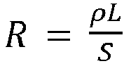
- Based on the formula

- It should be noted that when the resistivity, the winding length, and/or the winding diameter of the first coil and/or the second coil are/is increased and/or reduced, mass of the first coil and/or the second coil may also change. However, the mass of the coil also affects the vibration of the first mechanical structure. Therefore, when parameters such as the resistivity, the winding length, and/or the winding diameter are adjusted, impact of other parameters also needs to be considered, so that the amplitude of the first mechanical structure is consistent with the amplitude of the second mechanical structure.
- In some embodiments, a power amplification circuit may be disposed in the sound output device. The power amplification circuit may be disposed between the first speaker and the signal processing circuit. The first electrical signal output by the signal processing circuit passes through the power amplification circuit. The power amplification circuit amplifies the first electrical signal and outputs the first electrical signal to the first speaker. The first speaker receives the amplified first electrical signal. Therefore, the first excitation F1 generated by the first speaker is greater than the second excitation F2 generated by the second speaker (that is, F1 > F2). With reference to the formula (6), the first excitation F1 is greater than the second excitation F2, so that X1 may be consistent with X2. In this case, power of the first sound wave is the same as power of the second sound wave, and the volume of the first sound wave heard by the user is the same as the volume of the second sound wave. In this way, the volume difference caused by the mass difference between the first mechanical structure and the second mechanical structure is corrected.
- In some embodiments, a power attenuation circuit may be disposed in the sound output device. The power attenuation circuit may be disposed between the second speaker and the signal processing circuit. The second electrical signal output by the signal processing circuit passes through the power attenuation circuit. The power attenuation circuit attenuates the second electrical signal and outputs the second electrical signal to the second speaker. The second speaker receives the attenuated second electrical signal. Therefore, the second excitation F2 generated by the second speaker is less than the first excitation F1 generated by the first speaker (that is, F1 > F2). With reference to the formula (6), the first excitation F1 is greater than the second excitation F2, so that X1 may be consistent with X2. In this case, power of the first sound wave the same as power of the second sound wave, and the volume of the first sound wave heard by the user is the same as the volume of the second sound wave. In this way, the volume difference caused by the mass difference between the first mechanical structure and the second mechanical structure is corrected.
- Based on the foregoing description, when there is a volume difference between two ends of the earphone, a sensory sound source perceived by the user will shift. Therefore, the sound output device needs to be designed properly to reduce the shift of the sensory sound source output by the sound output device as much as possible.
- Therefore, this application further provides a sound output device. The sound output device may include but is not limited to an earphone, a hearing aid, a helmet, or the like. The earphone may include but is not limited to a wired earphone, a wireless earphone, a Bluetooth earphone, or the like. Specifically, the sound output device may include a first speaker, a second speaker, and a signal processing circuit.
- The signal processing circuit may receive target sound information, process the target sound information, and generate a first electrical signal and a second electrical signal.
- The first speaker is electrically connected to the signal processing circuit. The first speaker may receive the first electrical signal from the signal processing circuit and convert the first electrical signal into a first sound wave. In some embodiments, the first speaker includes a first bone-conduction speaker, and the first sound wave includes a first bone-conducted sound wave. In some embodiments, the first speaker may convert the received first electrical signal into a mechanical vibration. Further, the first sound wave is generated by the mechanical vibration. In some embodiments, the first speaker may include a first mechanical structure and a first excitation device. The first excitation device generates a first excitation based on the first electrical signal. The first excitation, as an external force, excites the first mechanical structure to vibrate. Further, the first mechanical structure vibrates to generate the first sound wave.
- The second speaker is electrically connected to the signal processing circuit. The second speaker may receive the second electrical signal from the signal processing circuit and convert the second electrical signal into a second sound wave. In some embodiments, the second speaker includes a second bone-conduction speaker, and the second sound wave includes a second bone-conducted sound wave. In some embodiments, the second speaker may convert the received second electrical signal into a mechanical vibration. Further, the second sound wave is generated by the mechanical vibration. In some embodiments, the second speaker may include a second mechanical structure and a second excitation device. The second excitation device generates a second excitation based on the second electrical signal. The second excitation, as an external force, excites the second mechanical structure to vibrate. Further, the second mechanical structure vibrates to generate the second sound wave.
- In some embodiments, the first excitation device and the second excitation device may be electromagnetic excitation devices. A value of the first excitation and a value of the second excitation may be obtained through calculation based on the formula (1). A vibration process of the first mechanical structure and the second mechanical structure may be expressed by the formula (6).
- For ease of description, in the following description of this application, F1 indicates the value of the first excitation, F2 indicates the value of the second excitation, M1 indicates mass of the first mechanical structure, M2 indicates mass of the second mechanical structure, S1 indicates a winding cross-sectional area of a first coil, S2 indicates a winding cross-sectional area of a second coil, ρ1 indicates a winding resistivity of the first coil, ρ2 indicates a winding resistivity of the second coil, B1 indicates a magnetic field strength of a first magnetic member, B2 indicates a magnetic field strength of a second magnetic member, R1 indicates a winding resistance of the first coil (hereinafter referred to as a first resistance), R2 indicates a winding resistance of the second coil (hereinafter referred to as a second resistance), X1 indicates an amplitude of the first mechanical structure, and X2 indicates an amplitude of the second mechanical structure.
- Given input electrical signals with a same amplitude and frequency, volume of a sound wave output by the first speaker is lower than volume of a sound wave output by the second speaker. For example, in some embodiments, mass M1 of the first mechanical structure is greater than mass M2 of the second mechanical structure, and consequently, given the input electrical signals with the same amplitude and frequency, volume of the sound wave output by the first speaker is lower than volume of the sound wave output by the second speaker. Referring to the formula (1) and the formula (6), assuming that both an amplitude and a frequency of the first electrical signal are the same as those of the second electrical signal (that is, U1 = U2), and that the first excitation device and the second excitation device are the same (that is, B1 = B2, S1 = S2, P1 = ρ2, and R1 = R2), without considering damping and rigidity differences (that is, C1 = C2, and K1 = K2), it may be concluded based on the formula (1) and the formula (6) that the first excitation F1 and the second excitation F2 are the same (F1 = F2). Based on the foregoing assumption, because M1 > M2, as may be known from a relationship between mass and an amplitude, the amplitude of the first mechanical structure is less than the amplitude of the second mechanical structure. When transmission media and transmission distances are the same, volume of the sound wave generated by the first speaker and heard by a user is lower than volume of the sound wave generated by the second speaker. For example, given input electrical signals with a same amplitude and frequency, a volume difference between the first sound wave and the second sound wave is not greater than 3 dB.
- For ease of description, in the following description of this application, perceiving the target sound information by the user is described by using an example in which the first sound wave is transmitted to a left ear of the user and the second sound wave is transmitted to a right ear of the user. Assuming that all information other than the volume are held constant for the first sound wave and the second sound wave, based on a binaural effect, when the volume of the first sound wave heard by the left ear of the user is lower than the volume of the second sound wave heard by the right ear of the user. In this case, the brain of the user determines that a sound generation location (that is, a sensory sound source perceived by the user) of the target sound information leans to a right side, that is, one side of the second sound wave with higher volume.
- Based on the binaural effect, a "phase difference" and/or a "time difference" may be used to resolve a sensory sound source shift caused by the "volume difference".
- In some embodiments, a first duration t1 is required for the
sound output device 300 to convert the targetsound information 10 into thefirst sound wave 21 and a second duration t2 is required for thesound output device 300 to convert the targetsound information 10 into thesecond sound wave 22; and the first duration t1 is shorter than the second duration t2 by one time difference δt. Therefore, a moment when thefirst speaker 310 generates a sound is earlier than a moment when thefirst speaker 310 generates a sound by the time difference δt. In some embodiments, the time difference δt is not greater than 3 ms. Specifically, the time difference δt may be any one of the following values or any value between any two of the following values: 0.1 ms, 0.2 ms, 0.3 ms, 0.4 ms, 0.5 ms, 0.6 ms, 0.7 ms, 0.8 ms, 0.9 ms, 1.0 ms, 1.1 ms, 1.2 ms, 1.3 ms, 1.4 ms, 1.5 ms, 1.6 ms, 1.7 ms, 1.8 ms, 1.9 ms, 2.0 ms, 2.1 ms, 2.2 ms, 2.3 ms, 2.4 ms, 2.5 ms, 2.6 ms, 2.7 ms, 2.8 ms, 2.9 ms, and 3.0 ms. For example, the time difference δt may be 1.0 ms, or a value slightly greater than 1.0 ms. Assuming that all other information than the time of sound generation are held constant for thefirst sound wave 21 and thesecond sound wave 22. When transmission media and transmission distances are the same, a moment when hearing thefirst sound wave 21 by the left ear of the user is earlier than a moment when hearing thesecond sound wave 22. Based on the binaural effect, a source location (that is, a sensory sound source perceived by the user) of the targetsound information 10 heard by the user is corrected. - In some embodiments, the time difference occurs in a process in which the first speaker converts the first electrical signal into the first sound wave and the second speaker converts the second electrical signal into the second sound wave. For example, a time advancement circuit may be disposed in the first speaker and/or a time delay circuit may be disposed in the second speaker, so that the first sound wave output by the first speaker is earlier than the second sound wave output by the second speaker. In some embodiments, the first sound wave is earlier than the second sound wave by one time difference δt.
- In some embodiments, the time difference occurs in a process in which the sound output device converts the target sound information into the first electrical signal and the second electrical signal. For example, a time processing circuit may be disposed in the signal processing circuit, so that the first electrical signal input to the first speaker is earlier than the second electrical signal input to the second speaker. In some embodiments, the first electrical signal is earlier than the second electrical signal by one time difference δt.
- In some embodiments, there is a first phase difference δw1 between the second sound wave and the first sound wave. In some embodiments, a phase of the first sound wave is greater than a phase of the second sound wave by δw1. Assuming that all other information than the phases stays constant for the first sound wave and the second sound wave, based on the binaural effect, the brain of the user determines that a source location (that is, a sensory sound source perceived by the user) of the target sound information leans to one side of the first sound wave with a larger phase, that is, a left side of the user. Therefore, considering a right shift of the sensory sound source due to the volume of the first sound wave is lower than the volume of the second sound wave, the source location of the target sound information heard by the user is adjusted to a center position. This may offset the sensory sound source shift due to the mass of the first mechanical structure being greater than the mass of the second mechanical structure.
- In some embodiments, a phase of the second electrical signal is the same as a phase of the first electrical signal. For example, the signal processing circuit may process the target sound information, so that the phase of the generated first electrical signal is the same as the phase of the second electrical signal. Further, a phase delay circuit may be disposed in the second speaker. The phase delay circuit may delay the second electrical signal by δw1, and generate the second sound wave in which the phase is also delayed by δw1. Therefore, the phase of the first sound wave may be greater than the phase of the second sound wave by δw1. This may offset the sensory sound source shift due to the mass of the first mechanical structure being greater than the mass of the second mechanical structure.
- In some embodiments, there is a second phase difference δw2 between the second electrical signal and the first electrical signal; and the second phase difference δw2 is the same as the first phase difference δw1. For example, a phase delay circuit may be disposed in the signal processing circuit. The signal processing circuit may process the target sound information to obtain the first electrical signal and the second electrical signal. In addition, there is the second phase difference δw2 between the first electrical signal and the second electrical signal. For example, a phase of the first electrical signal is greater than a phase of the second electrical signal by δw2. The first speaker and the second speaker do not change the phase of the first electrical signal and the phase of the second electrical signal. Therefore, the phase of the first sound wave generated by the first speaker is greater than the phase of the second sound wave generated by the second speaker by δw2. However, δw2 is the same as δw1, that is, the final phase of the first sound wave is greater than the final phase of the second sound wave by δw1. This may also offset the sensory sound source shift due to the mass of the first mechanical structure being greater than the mass of the second mechanical structure.
- Therefore, for the target sound information, the moment when the first speaker generates the sound is earlier than the moment when the second speaker generates the sound. Assuming that all other information except the time of sound generation stays the same for the first sound wave and the second sound wave. When transmission media and transmission distances are the same, the moment when hearing the first sound wave by the left ear of the user is earlier than the moment when hearing the second sound wave by the right ear of the user. Based on the binaural effect, the brain of the user perceive that a source location of the target sound information leans to a side of the first sound wave in which the sound is generated earlier, that is, the left side of the user. Therefore, considering the right shift of the sensory sound source due to the volume of the first sound wave being lower than the volume of the second sound wave, the source location (that is, the sensory sound source perceived by the user) of the target sound information heard by the user may be adjusted to the center position. This may offset the right shift of the sensory sound source due to the mass of the first mechanical structure being greater than the mass of the second mechanical structure.
- As described above, this application provides a sensory sound source adjustment method S100, a volume adjustment method S200, and two sound output devices. The sensory sound source adjustment method S100 in this application includes: S110, obtaining a volume difference between the first sound wave and the second sound wave; and S120, adjusting a sound generation time difference between the first sound wave and the second sound wave. The volume adjustment method S200 in this application includes: S210, obtaining a volume difference between the first sound wave and the second sound wave; and S220, adjusting an amplitude difference between the first excitation and the second excitation. In the sound output device and the sensory sound source adjustment method S100 in this application, the shift of the sensory sound source perceived by the user, which is caused by the mass difference between the first mechanical structure and the second mechanical structure, is corrected by setting the time difference between the first sound wave and the second sound wave. In the sound output device and the volume adjustment method in this application, the volume difference between the first speaker and the second speaker, which is caused by the mass difference between the first mechanical structure and the second mechanical structure, is corrected by setting different coil resistivities, coil winding diameters, magnetic field strengths, and/or resistances.
- It should be noted that the scope of this application is not limited by the transmission media of the first sound wave and/or the second sound wave in this application. The first sound wave and/or the second sound wave in the present disclosure may be transmitted through a solid substance (for example, bones), and the first sound wave and/or the second sound wave may be transmitted by gas (for example, air). In some embodiments, the transmission media may include one or a combination of air and bones.
- It should be noted that in actual design and manufacturing, the volume adjustment method, the sensory sound source adjustment method, and the sound output device in this application may be used in combination, to achieve a desired adjustment. For example, in some embodiments, the sensory sound source adjustment method S100 may be separately used to adjust the sensory sound source output by the sound output device. For example, in some embodiments, the volume adjustment method S200 and the sensory sound source adjustment method S100 may be used simultaneously to adjust the sensory sound source and the sound volume output by the sound output device.
- For example, a mass adjustment and an excitation adjustment may be performed simultaneously. For example, when M1 > M2, methods such as "increasing the mass of the second
mechanical structure 311", "increasing the first excitation", and "increasing the diameter of the first coil" may be used simultaneously, so that the volume of thefirst speaker 310 is consistent with the volume of thesecond speaker 320. - For example, when M1 > M2, methods such as "increasing the mass of the second
mechanical structure 311", "increasing the first excitation", and "reducing the diameter of the second coil" may be used simultaneously, so that the volume difference between thefirst speaker 310 and thesecond speaker 320 is maintained within a target volume difference range; and then a method for setting a phase difference may be used simultaneously to adjust the sensory sound source. - It should be noted that the volume of the first speaker and the volume of the second speaker remain "consistent" or "the same", only for the ease of analysis, and should not constitute a limitation on the protection scope of this application. The volume of the first speaker remains consistent with or the same as the volume of the second speaker may be that the volume difference between the first speaker and the second speaker is maintained within the target volume difference range.
- It should be noted that the requirement in which the sensory sound source of the sound output device is "centered" in this application, is only for the ease of analysis, and should not constitute a limitation on the protection scope of the present disclosure. The sensory sound source is centered may be that the sensory sound source is maintained in a target location range.
- In summary, after reading details of the present disclosure, a person skilled in the art may understand that details of the present disclosure may be presented by using examples only, and may not be limiting. A person skilled in the art may understand that this application is intended to cover various reasonable changes, improvements, and modifications to the embodiments, although this is not specified herein. These changes, improvements, and modifications are intended to be proposed in the present disclosure and are within the spirit and scope of the exemplary embodiments of the present disclosure.
- The terms used herein are only intended to describe specific exemplary embodiments and are not restrictive. For example, unless otherwise clearly indicated in a context, the terms "a", "an", "said", and "the" in singular forms may also include plural forms. When used in this specification, the terms "comprising", "including", and/or "containing" indicate presence of associated integers, steps, operations, elements, and/or components. However, this does not exclude presence of one or more other features, integers, steps, operations, elements, components, and/or groups or addition of other features, integers, steps, operations, elements, components, and/or groups to the system/method. When used in this specification, the term "A is above B" may mean that A is directly adjacent to B (above or below B), or may mean that A is indirectly adjacent to B (that is, A and B are separated by some substances); and the term "A is in B" may mean that A is completely in B, or may mean that A is partially in B.
- In addition, some terms in this application are used to describe the embodiments of the present disclosure. For example, "one embodiment", "an embodiment", and/or "some embodiments" mean/means that a specific feature, structure, or characteristic described with reference to the embodiment(s) may be included in at least one embodiment of the present disclosure. Therefore, it should be emphasized and should be understood that two or more references to "an embodiment" or "one embodiment" or "alternative embodiment" in various parts of this specification do not necessarily all refer to the same embodiment. In addition, specific features, structures, or characteristics may be appropriately combined in one or more embodiments of the present disclosure.
- It should be understood that in the foregoing description of the embodiments of the present disclosure, to facilitate understanding of one feature, for the purpose of simplifying the present disclosure, various features in this application are sometimes combined in a single embodiment, single drawing, or description thereof. Alternatively, various features in this application are distributed in a plurality of embodiments of the present invention. However, this does not mean that the combination of these features is necessary. It is entirely possible for a person skilled in the art to extract some of the features as a separate exemplary embodiment for understanding when reading the present disclosure. In other words, an embodiment in this application may also be understood as an integration of a plurality of subembodiments. It is also true when content of each sub-embodiment is less than all features of a single embodiment disclosed above.
- In some implementation solutions, numbers expressing quantities or properties used to describe and seek to protect some implementation solutions of this application should be understood as modified by the term "about", "approximately", or "basically" in some cases. For example, unless otherwise specified, the term "about", "approximately", or "basically" may mean a ±20% variation of a value described by the term. Therefore, in some implementation solutions, numerical parameters listed in the written description and appended claims are approximate values, which may vary according to desired properties that a particular implementation solution is trying to achieve. In some implementation solutions, numerical parameters should be interpreted based on a quantity of significant figures reported and by applying common rounding techniques. Although some implementation solutions described in this application list a wide range of numerical values and the parameters, such range of numerical values and the parameters are only approximations, in the present disclosure, precise numerical values are provided when possible.
- Each patent, patent application, patent application publication, and other materials cited herein, such as articles, books, specifications, publications, documents, and materials may be incorporated herein by reference. All content used for all purposes, except any prosecution document history related to the content, any identical prosecution document history that may be inconsistent or conflict with this document, or any identical prosecution document history that may have restrictive impact on the broadest scope of the claims, is associated with this document now or later. For example, if there is any inconsistency or conflict between descriptions, definitions, and/or use of terms associated with any material contained therein and descriptions, definitions, and/or use of terms related to this document, the terms in this document shall prevail.
- Finally, it should be understood that the implementation solutions of this application disclosed in this specification are descriptions of principles of the implementation solutions of this application. Other modified embodiments also fall within the scope of this application. Therefore, the embodiments disclosed in this application are merely exemplary and not restrictive. A person skilled in the art may use alternative configurations according to the embodiments of this application to implement the invention in this application. Therefore, the embodiments of this application are not limited to those precisely described in this application.
Claims (22)
- A sound output device, characterized by comprising:a signal processing circuit to generate, during operation, a first electrical signal and a second electrical signal based on target sound information;a first speaker, electrically connected to the signal processing circuit to receive, during operation, the first electrical signal from the signal processing circuit and convert the first electrical signal into a first sound wave; anda second speaker, electrically connected to the signal processing circuit to receive, during operation, the second electrical signal from the signal processing circuit and convert the second electrical signal into a second sound wave, whereinthe sound output device converts the target sound information into the first sound wave in a first duration and further converts the target sound information into the second sound wave in a second duration, andthe first duration is shorter than the second duration by a time difference.
- The sound output device according to claim 1, characterized in that, when given input electrical signals with a same amplitude and frequency, volume of a sound wave output by the first speaker is lower than volume of a sound wave output by the second speaker.
- The sound output device according to claim 2, characterized in that, when given the input electrical signals with a same amplitude and frequency, a difference between the volume of the first sound wave and the volume of the second sound wave is not greater than 3 dB.
- The sound output device according to claim 2, characterized in that, the first speaker generates the first sound wave by exciting a first mechanical structure; andthe second speaker generates the second sound wave by exciting a second mechanical structure, whereinmass of the first mechanical structure is greater than mass of the second mechanical structure, so that when given the input electrical signals with the same amplitude and frequency, the volume of the sound wave output by the first speaker is lower than the volume of the sound wave output by the second speaker.
- The sound output device according to claim 2, characterized in that, the first speaker includes at least one of a first bone-conduction speaker or a first air-conduction speaker; and
the second speaker includes at least one of a second bone-conduction speaker or a second air-conduction speaker. - The sound output device according to claim 1, characterized in that, the time difference occurs in a process in which the sound output device converts the target sound information into the first electrical signal and the second electrical signal.
- The sound output device according to claim 1, characterized in that, the time difference occurs in a process in which the first speaker converts the first electrical signal into the first sound wave and the second speaker converts the second electrical signal into the second sound wave.
- The sound output device according to claim 1, characterized in that, the time difference is not greater than 3 ms.
- A sound output device, characterized by comprising:a signal processing circuit to generate, during operation, a first electrical signal and a second electrical signal based on target sound information;a first speaker, electrically connected to the signal processing circuit to receive, during operation, the first electrical signal from the signal processing circuit and convert the first electrical signal into a first excitation to excite a first mechanical structure to generate a first sound wave; anda second speaker, electrically connected to the signal processing circuit to receive, during operation, the second electrical signal from the signal processing circuit and convert the second electrical signal into a second excitation to excite a second mechanical structure to generate a second sound wave, whereinvolume of the first sound wave is the same as volume of the second sound wave, andgiven a same excitation, sound volume generated by the first mechanical structure is lower than sound volume generated by the second mechanical structure.
- The sound output device according to claim 9, characterized in that, mass of the first mechanical structure is greater than mass of the second mechanical structure, so that when given a same excitation, the sound volume generated by the first mechanical structure is lower than the sound volume generated by the second mechanical structure.
- The sound output device according to claim 10, characterized in that, the first speaker includes at least one of a first bone-conduction speaker or a first air-conduction speaker; and
the second speaker includes at least one of a second bone-conduction speaker or a second air-conduction speaker. - The sound output device according to claim 10, characterized in that,the first speaker further includes a first electromagnetic excitation device to generate the first excitation to excite the first mechanical structure to vibrate and generate the first sound wave; andthe second speaker further includes a second electromagnetic excitation device to generate the second excitation to excite the second mechanical structure to vibrate and generate the second sound wave.
- The sound output device according to claim 12, characterized in that,the first electromagnetic excitation device includes a first coil; andthe second electromagnetic excitation device includes a second coil, whereina winding diameter of the first coil is greater than a winding diameter of the second coil.
- The sound output device according to claim 12, characterized in that,the first electromagnetic excitation device includes a first coil; andthe second electromagnetic excitation device includes a second coil, whereina resistivity of the first coil is less than a resistivity of the second coil.
- The sound output device according to claim 12, characterized in that, given a same input current, the first excitation generated by the first electromagnetic excitation device is greater than the second excitation generated by the second electromagnetic excitation device.
- The sound output device according to claim 12, characterized in that,the first speaker includes a first resistance; andthe second speaker includes a second resistance, whereinthe first resistance is less than the second resistance.
- The sound output device according to claim 12, characterized by further comprising:a power amplification circuit connected to the first speaker and the signal processing circuit, whereinthe power amplification circuit amplifies the first electrical signal, andthe first speaker receives an amplified first electrical signal.
- The sound output device according to claim 12, characterized by further comprising:a power attenuation circuit connected to the second speaker and the signal processing circuit, whereinthe power attenuation circuit attenuates the second electrical signal, andthe second speaker receives an attenuated second electrical signal.
- A sensory sound source adjustment method, configured to adjust sensory sound sources of the first speaker and the second speaker of the sound output device according to any one of claims 1 to 8 and characterized by comprising:obtaining a volume difference between the first sound wave and the second sound wave; andadjusting the time difference.
- The sensory sound source adjustment method according to claim 19, characterized in that, the volume difference between the first sound wave and the second sound wave is not greater than 3 dB.
- The sensory sound source adjustment method according to claim 19, characterized in that, the adjusting of the time difference between the first sound wave and the second sound wave includes:
adjusting a phase difference between the first sound wave and the second sound wave. - A volume adjustment method, configured to adjust volume of the first speaker and the second speaker of the sound output apparatus according to any one of claims 9 to 18 and characterized by comprising:obtaining a volume difference between the first sound wave and the second sound wave; andadjusting an amplitude difference between the first excitation and the second excitation.
Applications Claiming Priority (1)
| Application Number | Priority Date | Filing Date | Title |
|---|---|---|---|
| PCT/CN2020/088524 WO2021217670A1 (en) | 2020-04-30 | 2020-04-30 | Sound output device, sound image adjustment method and volume adjustment method |
Publications (4)
| Publication Number | Publication Date |
|---|---|
| EP4124067A1 true EP4124067A1 (en) | 2023-01-25 |
| EP4124067A4 EP4124067A4 (en) | 2024-04-10 |
| EP4124067C0 EP4124067C0 (en) | 2025-12-10 |
| EP4124067B1 EP4124067B1 (en) | 2025-12-10 |
Family
ID=78373162
Family Applications (1)
| Application Number | Title | Priority Date | Filing Date |
|---|---|---|---|
| EP20933329.3A Active EP4124067B1 (en) | 2020-04-30 | 2020-04-30 | Sound output device |
Country Status (6)
| Country | Link |
|---|---|
| US (2) | US12212942B2 (en) |
| EP (1) | EP4124067B1 (en) |
| JP (2) | JP7624456B2 (en) |
| KR (1) | KR102696599B1 (en) |
| CN (1) | CN115280795A (en) |
| WO (1) | WO2021217670A1 (en) |
Family Cites Families (37)
| Publication number | Priority date | Publication date | Assignee | Title |
|---|---|---|---|---|
| JPH06121395A (en) * | 1992-10-01 | 1994-04-28 | Fujitsu Ten Ltd | Listening position automatic correction device |
| JPH11103495A (en) | 1997-09-29 | 1999-04-13 | Yoshiki Kogyo Kk | Phase compensation system for audio reproducer |
| JP3514639B2 (en) * | 1998-09-30 | 2004-03-31 | 株式会社アーニス・サウンド・テクノロジーズ | Method for out-of-head localization of sound image in listening to reproduced sound using headphones, and apparatus therefor |
| KR100416757B1 (en) | 1999-06-10 | 2004-01-31 | 삼성전자주식회사 | Multi-channel audio reproduction apparatus and method for loud-speaker reproduction |
| US7031474B1 (en) * | 1999-10-04 | 2006-04-18 | Srs Labs, Inc. | Acoustic correction apparatus |
| KR100390003B1 (en) * | 2002-10-02 | 2003-07-04 | Joo Bae Kim | Bone-conduction speaker using vibration plate and mobile telephone using the same |
| US7551749B2 (en) * | 2002-08-23 | 2009-06-23 | Bose Corporation | Baffle vibration reducing |
| JP2005223713A (en) * | 2004-02-06 | 2005-08-18 | Sony Corp | Sound reproducing apparatus and sound reproducing method |
| JP2006157106A (en) * | 2004-11-25 | 2006-06-15 | Victor Co Of Japan Ltd | Apparatus and system for reproducing sound |
| JP2006324898A (en) | 2005-05-18 | 2006-11-30 | Sony Corp | Audio playback device |
| WO2007017809A1 (en) * | 2005-08-05 | 2007-02-15 | Koninklijke Philips Electronics N.V. | A device for and a method of processing audio data |
| CN1805616A (en) | 2005-12-29 | 2006-07-19 | 颜怀伟 | Integrate three-voice coil loudspeaker and its power amplifier and control circuit |
| CN1812653B (en) | 2005-12-29 | 2011-12-07 | 颜怀伟 | Variable impedance and power loudspeaker and power amplification and control circuit thereof |
| CN1819717B (en) | 2005-12-29 | 2012-04-25 | 颜怀伟 | Three-level magnetic pole lound speaker and its playing and controlling circuit |
| KR100872762B1 (en) | 2008-03-04 | 2008-12-09 | 팜쉬주식회사 | Voice coil structure and bone conduction speaker for bone conduction speaker |
| FI20090218A0 (en) | 2009-05-29 | 2009-05-29 | Aura Audio Oy | Subwoofer structure |
| US9100766B2 (en) | 2009-10-05 | 2015-08-04 | Harman International Industries, Inc. | Multichannel audio system having audio channel compensation |
| CN101867852A (en) * | 2010-07-01 | 2010-10-20 | 深圳市特灵通数码通讯发展有限公司 | Bone conduction earphone based on dual-channel frequency difference and short sound stimulation double actions |
| US9020168B2 (en) | 2011-08-30 | 2015-04-28 | Nokia Corporation | Apparatus and method for audio delivery with different sound conduction transducers |
| WO2013114864A1 (en) * | 2012-01-30 | 2013-08-08 | パナソニック株式会社 | Earphone |
| JP5812926B2 (en) | 2012-04-12 | 2015-11-17 | 京セラ株式会社 | Electronics |
| US8965028B2 (en) * | 2012-08-23 | 2015-02-24 | Skullcandy, Inc. | Speakers, headphones, and kits related to vibrations in an audio system, and methods for forming same |
| WO2015029205A1 (en) | 2013-08-30 | 2015-03-05 | 共栄エンジニアリング株式会社 | Sound processing apparatus, sound processing method, and sound processing program |
| US20150170633A1 (en) * | 2013-12-17 | 2015-06-18 | Kabushiki Kaisha Toshiba | Bone-conduction noise cancelling headphones |
| JP6492331B2 (en) | 2014-03-19 | 2019-04-03 | ソニー株式会社 | Sound output device |
| CN107113525A (en) * | 2014-12-30 | 2017-08-29 | 高迪音频实验室公司 | For the method and apparatus for the binaural audio signal for handling generation additional stimulus |
| CN104936096B (en) * | 2015-05-29 | 2018-07-17 | 京东方科技集团股份有限公司 | Bone conduction sound propagation device and method |
| CN106714017B (en) * | 2015-07-17 | 2019-08-23 | 中兴通讯股份有限公司 | Method, device, terminal and earphone for adjusting sound field of earphone |
| KR102359696B1 (en) * | 2015-08-13 | 2022-02-09 | 션젼 복스테크 컴퍼니 리미티드 | bone conduction loudspeaker |
| KR20170062853A (en) * | 2015-11-30 | 2017-06-08 | 삼성전자주식회사 | Electronic device and operating method thereof |
| WO2017097337A1 (en) | 2015-12-08 | 2017-06-15 | Huawei Technologies Co., Ltd. | User device and method for driving a speaker in the user device |
| US9774979B1 (en) * | 2016-03-03 | 2017-09-26 | Google Inc. | Systems and methods for spatial audio adjustment |
| CN107888857A (en) * | 2017-11-17 | 2018-04-06 | 青岛海信电器股份有限公司 | For the method for adjustment of sound field, device and separate television in separate television |
| CN209120433U (en) | 2018-06-15 | 2019-07-16 | 深圳市韶音科技有限公司 | A bone conduction speaker |
| CN110611865B (en) | 2018-06-15 | 2024-12-17 | 深圳市韶音科技有限公司 | Bone conduction loudspeaker and earphone |
| CN109547906B (en) * | 2019-01-05 | 2023-12-08 | 深圳市韶音科技有限公司 | Bone conduction speaker device |
| CN110262768A (en) | 2019-06-15 | 2019-09-20 | 常德沁音科技有限公司 | A kind of adjusting method and bluetooth headset of left and right power of hearing amount relative equilibrium |
-
2020
- 2020-04-30 JP JP2022564494A patent/JP7624456B2/en active Active
- 2020-04-30 KR KR1020227037921A patent/KR102696599B1/en active Active
- 2020-04-30 EP EP20933329.3A patent/EP4124067B1/en active Active
- 2020-04-30 WO PCT/CN2020/088524 patent/WO2021217670A1/en not_active Ceased
- 2020-04-30 CN CN202080098386.8A patent/CN115280795A/en active Pending
-
2022
- 2022-09-01 US US17/901,813 patent/US12212942B2/en active Active
-
2024
- 2024-09-09 JP JP2024154710A patent/JP7809769B2/en active Active
- 2024-12-17 US US18/984,905 patent/US20250119689A1/en active Pending
Also Published As
| Publication number | Publication date |
|---|---|
| EP4124067C0 (en) | 2025-12-10 |
| EP4124067A4 (en) | 2024-04-10 |
| BR112022018744A2 (en) | 2022-11-08 |
| KR102696599B1 (en) | 2024-08-21 |
| US20230007399A1 (en) | 2023-01-05 |
| US12212942B2 (en) | 2025-01-28 |
| US20250119689A1 (en) | 2025-04-10 |
| JP7624456B2 (en) | 2025-01-30 |
| JP7809769B2 (en) | 2026-02-02 |
| JP2023523739A (en) | 2023-06-07 |
| JP2024170585A (en) | 2024-12-10 |
| CN115280795A (en) | 2022-11-01 |
| KR20220161447A (en) | 2022-12-06 |
| WO2021217670A1 (en) | 2021-11-04 |
| EP4124067B1 (en) | 2025-12-10 |
Similar Documents
| Publication | Publication Date | Title |
|---|---|---|
| US7499555B1 (en) | Personal communication method and apparatus with acoustic stray field cancellation | |
| US9538283B2 (en) | Ear microphone | |
| US5949896A (en) | Earphone | |
| CN115334435A (en) | Hearing assisting device | |
| US11095992B2 (en) | Hearing aid and method for use of same | |
| US12200447B2 (en) | Assistive listening devices | |
| KR20070038389A (en) | Enhanced phone handset | |
| CN113596647B (en) | Sound output device and method for adjusting sound and image | |
| TW202236866A (en) | Hearing aid device | |
| CN113596684B (en) | Sound output device and method for adjusting volume | |
| US12212942B2 (en) | Sound output device, sensory sound source adjustment method, and volume adjustment method | |
| KR20190110389A (en) | Earphone Assembled Aero Conduction Transducer and Bone Conduction Transducer | |
| HK40079195A (en) | Sound output device, sound image adjustment method and volume adjustment method | |
| EP4498363A1 (en) | Open-ear wearable acoustic device and active noise cancellation method thereof | |
| EP4498702A1 (en) | Open wearable acoustic device and active noise reduction method | |
| RU2804725C1 (en) | Sound output device, method for adjusting imaginary source and method for adjusting volume | |
| US20260046562A1 (en) | Sound output devices | |
| BR112022018744B1 (en) | SOUND OUTPUT DEVICE, SENSORY SOUND SOURCE ADJUSTMENT METHOD AND VOLUME ADJUSTMENT METHOD | |
| US20250006169A1 (en) | Open wearable acoustic device and active noise reduction method | |
| EP4498695A1 (en) | Open wearable acoustic device and active noise cancellation method | |
| RU2801638C1 (en) | Hearing aid devices | |
| RU2797339C1 (en) | Audio output device | |
| US20210306768A1 (en) | Hearing Aid and Method for Use of Same | |
| CN115004718A (en) | Hearing aids and how to use them |
Legal Events
| Date | Code | Title | Description |
|---|---|---|---|
| STAA | Information on the status of an ep patent application or granted ep patent |
Free format text: STATUS: THE INTERNATIONAL PUBLICATION HAS BEEN MADE |
|
| PUAI | Public reference made under article 153(3) epc to a published international application that has entered the european phase |
Free format text: ORIGINAL CODE: 0009012 |
|
| STAA | Information on the status of an ep patent application or granted ep patent |
Free format text: STATUS: REQUEST FOR EXAMINATION WAS MADE |
|
| 17P | Request for examination filed |
Effective date: 20221019 |
|
| AK | Designated contracting states |
Kind code of ref document: A1 Designated state(s): AL AT BE BG CH CY CZ DE DK EE ES FI FR GB GR HR HU IE IS IT LI LT LU LV MC MK MT NL NO PL PT RO RS SE SI SK SM TR |
|
| REG | Reference to a national code |
Ref country code: HK Ref legal event code: DE Ref document number: 40079195 Country of ref document: HK |
|
| DAV | Request for validation of the european patent (deleted) | ||
| DAX | Request for extension of the european patent (deleted) | ||
| RIC1 | Information provided on ipc code assigned before grant |
Ipc: H04R 1/10 20060101ALI20231211BHEP Ipc: H04R 5/033 20060101ALI20231211BHEP Ipc: H04R 9/02 20060101AFI20231211BHEP |
|
| A4 | Supplementary search report drawn up and despatched |
Effective date: 20240312 |
|
| RIC1 | Information provided on ipc code assigned before grant |
Ipc: H04R 25/00 20060101ALI20240305BHEP Ipc: H04R 3/12 20060101ALI20240305BHEP Ipc: H04R 1/40 20060101ALI20240305BHEP Ipc: H04R 1/10 20060101ALI20240305BHEP Ipc: H04R 5/033 20060101ALI20240305BHEP Ipc: H04R 9/02 20060101AFI20240305BHEP |
|
| GRAP | Despatch of communication of intention to grant a patent |
Free format text: ORIGINAL CODE: EPIDOSNIGR1 |
|
| STAA | Information on the status of an ep patent application or granted ep patent |
Free format text: STATUS: GRANT OF PATENT IS INTENDED |
|
| INTG | Intention to grant announced |
Effective date: 20250909 |
|
| GRAS | Grant fee paid |
Free format text: ORIGINAL CODE: EPIDOSNIGR3 |
|
| GRAA | (expected) grant |
Free format text: ORIGINAL CODE: 0009210 |
|
| STAA | Information on the status of an ep patent application or granted ep patent |
Free format text: STATUS: THE PATENT HAS BEEN GRANTED |
|
| AK | Designated contracting states |
Kind code of ref document: B1 Designated state(s): AL AT BE BG CH CY CZ DE DK EE ES FI FR GB GR HR HU IE IS IT LI LT LU LV MC MK MT NL NO PL PT RO RS SE SI SK SM TR |
|
| REG | Reference to a national code |
Ref country code: CH Ref legal event code: F10 Free format text: ST27 STATUS EVENT CODE: U-0-0-F10-F00 (AS PROVIDED BY THE NATIONAL OFFICE) Effective date: 20251210 Ref country code: GB Ref legal event code: FG4D |
|
| REG | Reference to a national code |
Ref country code: DE Ref legal event code: R096 Ref document number: 602020063867 Country of ref document: DE |
|
| REG | Reference to a national code |
Ref country code: IE Ref legal event code: FG4D |
|
| U01 | Request for unitary effect filed |
Effective date: 20251218 |
|
| U07 | Unitary effect registered |
Designated state(s): AT BE BG DE DK EE FI FR IT LT LU LV MT NL PT RO SE SI Effective date: 20260102 |
|
| PG25 | Lapsed in a contracting state [announced via postgrant information from national office to epo] |
Ref country code: ES Free format text: LAPSE BECAUSE OF FAILURE TO SUBMIT A TRANSLATION OF THE DESCRIPTION OR TO PAY THE FEE WITHIN THE PRESCRIBED TIME-LIMIT Effective date: 20251210 |
|
| PG25 | Lapsed in a contracting state [announced via postgrant information from national office to epo] |
Ref country code: NO Free format text: LAPSE BECAUSE OF FAILURE TO SUBMIT A TRANSLATION OF THE DESCRIPTION OR TO PAY THE FEE WITHIN THE PRESCRIBED TIME-LIMIT Effective date: 20260310 |
|
| PG25 | Lapsed in a contracting state [announced via postgrant information from national office to epo] |
Ref country code: HR Free format text: LAPSE BECAUSE OF FAILURE TO SUBMIT A TRANSLATION OF THE DESCRIPTION OR TO PAY THE FEE WITHIN THE PRESCRIBED TIME-LIMIT Effective date: 20251210 |
|
| PG25 | Lapsed in a contracting state [announced via postgrant information from national office to epo] |
Ref country code: RS Free format text: LAPSE BECAUSE OF FAILURE TO SUBMIT A TRANSLATION OF THE DESCRIPTION OR TO PAY THE FEE WITHIN THE PRESCRIBED TIME-LIMIT Effective date: 20260310 |