EP4123838A1 - Connection assembly, connector, and connector assembly - Google Patents
Connection assembly, connector, and connector assembly Download PDFInfo
- Publication number
- EP4123838A1 EP4123838A1 EP22185590.1A EP22185590A EP4123838A1 EP 4123838 A1 EP4123838 A1 EP 4123838A1 EP 22185590 A EP22185590 A EP 22185590A EP 4123838 A1 EP4123838 A1 EP 4123838A1
- Authority
- EP
- European Patent Office
- Prior art keywords
- conductive plug
- conductive
- connection assembly
- connecting member
- connector
- Prior art date
- Legal status (The legal status is an assumption and is not a legal conclusion. Google has not performed a legal analysis and makes no representation as to the accuracy of the status listed.)
- Granted
Links
Images



Classifications
-
- H—ELECTRICITY
- H01—ELECTRIC ELEMENTS
- H01R—ELECTRICALLY-CONDUCTIVE CONNECTIONS; STRUCTURAL ASSOCIATIONS OF A PLURALITY OF MUTUALLY-INSULATED ELECTRICAL CONNECTING ELEMENTS; COUPLING DEVICES; CURRENT COLLECTORS
- H01R13/00—Details of coupling devices of the kinds covered by groups H01R12/70 or H01R24/00 - H01R33/00
- H01R13/62—Means for facilitating engagement or disengagement of coupling parts or for holding them in engagement
- H01R13/621—Bolt, set screw or screw clamp
-
- H—ELECTRICITY
- H01—ELECTRIC ELEMENTS
- H01R—ELECTRICALLY-CONDUCTIVE CONNECTIONS; STRUCTURAL ASSOCIATIONS OF A PLURALITY OF MUTUALLY-INSULATED ELECTRICAL CONNECTING ELEMENTS; COUPLING DEVICES; CURRENT COLLECTORS
- H01R11/00—Individual connecting elements providing two or more spaced connecting locations for conductive members which are, or may be, thereby interconnected, e.g. end pieces for wires or cables supported by the wire or cable and having means for facilitating electrical connection to some other wire, terminal, or conductive member, blocks of binding posts
- H01R11/11—End pieces or tapping pieces for wires, supported by the wire and for facilitating electrical connection to some other wire, terminal or conductive member
- H01R11/12—End pieces terminating in an eye, hook, or fork
-
- H—ELECTRICITY
- H01—ELECTRIC ELEMENTS
- H01R—ELECTRICALLY-CONDUCTIVE CONNECTIONS; STRUCTURAL ASSOCIATIONS OF A PLURALITY OF MUTUALLY-INSULATED ELECTRICAL CONNECTING ELEMENTS; COUPLING DEVICES; CURRENT COLLECTORS
- H01R4/00—Electrically-conductive connections between two or more conductive members in direct contact, i.e. touching one another; Means for effecting or maintaining such contact; Electrically-conductive connections having two or more spaced connecting locations for conductors and using contact members penetrating insulation
- H01R4/28—Clamped connections, spring connections
- H01R4/30—Clamped connections, spring connections utilising a screw or nut clamping member
- H01R4/34—Conductive members located under head of screw
-
- H—ELECTRICITY
- H01—ELECTRIC ELEMENTS
- H01R—ELECTRICALLY-CONDUCTIVE CONNECTIONS; STRUCTURAL ASSOCIATIONS OF A PLURALITY OF MUTUALLY-INSULATED ELECTRICAL CONNECTING ELEMENTS; COUPLING DEVICES; CURRENT COLLECTORS
- H01R11/00—Individual connecting elements providing two or more spaced connecting locations for conductive members which are, or may be, thereby interconnected, e.g. end pieces for wires or cables supported by the wire or cable and having means for facilitating electrical connection to some other wire, terminal, or conductive member, blocks of binding posts
- H01R11/11—End pieces or tapping pieces for wires, supported by the wire and for facilitating electrical connection to some other wire, terminal or conductive member
- H01R11/28—End pieces consisting of a ferrule or sleeve
-
- H—ELECTRICITY
- H01—ELECTRIC ELEMENTS
- H01R—ELECTRICALLY-CONDUCTIVE CONNECTIONS; STRUCTURAL ASSOCIATIONS OF A PLURALITY OF MUTUALLY-INSULATED ELECTRICAL CONNECTING ELEMENTS; COUPLING DEVICES; CURRENT COLLECTORS
- H01R13/00—Details of coupling devices of the kinds covered by groups H01R12/70 or H01R24/00 - H01R33/00
- H01R13/46—Bases; Cases
- H01R13/52—Dustproof, splashproof, drip-proof, waterproof, or flameproof cases
- H01R13/5202—Sealing means between parts of housing or between housing part and a wall, e.g. sealing rings
-
- H—ELECTRICITY
- H01—ELECTRIC ELEMENTS
- H01R—ELECTRICALLY-CONDUCTIVE CONNECTIONS; STRUCTURAL ASSOCIATIONS OF A PLURALITY OF MUTUALLY-INSULATED ELECTRICAL CONNECTING ELEMENTS; COUPLING DEVICES; CURRENT COLLECTORS
- H01R13/00—Details of coupling devices of the kinds covered by groups H01R12/70 or H01R24/00 - H01R33/00
- H01R13/46—Bases; Cases
- H01R13/53—Bases or cases for heavy duty; Bases or cases for high voltage with means for preventing corona or arcing
-
- H—ELECTRICITY
- H01—ELECTRIC ELEMENTS
- H01R—ELECTRICALLY-CONDUCTIVE CONNECTIONS; STRUCTURAL ASSOCIATIONS OF A PLURALITY OF MUTUALLY-INSULATED ELECTRICAL CONNECTING ELEMENTS; COUPLING DEVICES; CURRENT COLLECTORS
- H01R4/00—Electrically-conductive connections between two or more conductive members in direct contact, i.e. touching one another; Means for effecting or maintaining such contact; Electrically-conductive connections having two or more spaced connecting locations for conductors and using contact members penetrating insulation
- H01R4/22—End caps, i.e. of insulating or conductive material for covering or maintaining connections between wires entering the cap from the same end
-
- H—ELECTRICITY
- H01—ELECTRIC ELEMENTS
- H01R—ELECTRICALLY-CONDUCTIVE CONNECTIONS; STRUCTURAL ASSOCIATIONS OF A PLURALITY OF MUTUALLY-INSULATED ELECTRICAL CONNECTING ELEMENTS; COUPLING DEVICES; CURRENT COLLECTORS
- H01R4/00—Electrically-conductive connections between two or more conductive members in direct contact, i.e. touching one another; Means for effecting or maintaining such contact; Electrically-conductive connections having two or more spaced connecting locations for conductors and using contact members penetrating insulation
- H01R4/28—Clamped connections, spring connections
- H01R4/30—Clamped connections, spring connections utilising a screw or nut clamping member
- H01R4/305—Clamped connections, spring connections utilising a screw or nut clamping member having means for facilitating engagement of conductive member or for holding it in position
-
- H—ELECTRICITY
- H01—ELECTRIC ELEMENTS
- H01R—ELECTRICALLY-CONDUCTIVE CONNECTIONS; STRUCTURAL ASSOCIATIONS OF A PLURALITY OF MUTUALLY-INSULATED ELECTRICAL CONNECTING ELEMENTS; COUPLING DEVICES; CURRENT COLLECTORS
- H01R4/00—Electrically-conductive connections between two or more conductive members in direct contact, i.e. touching one another; Means for effecting or maintaining such contact; Electrically-conductive connections having two or more spaced connecting locations for conductors and using contact members penetrating insulation
- H01R4/70—Insulation of connections
-
- H—ELECTRICITY
- H01—ELECTRIC ELEMENTS
- H01R—ELECTRICALLY-CONDUCTIVE CONNECTIONS; STRUCTURAL ASSOCIATIONS OF A PLURALITY OF MUTUALLY-INSULATED ELECTRICAL CONNECTING ELEMENTS; COUPLING DEVICES; CURRENT COLLECTORS
- H01R2201/00—Connectors or connections adapted for particular applications
- H01R2201/26—Connectors or connections adapted for particular applications for vehicles
Definitions
- the mounting hole is usually not blocked and is in an open state, resulting in the connector having no waterproof and electromagnetic shielding functions.
- this will lead to the complexity of the housing and increase the production cost and operation difficulty of the connector.
- the present invention has been made to overcome or alleviate at least one aspect of the above mentioned disadvantages.
- the threaded fastener comprises a conductive threaded connecting member; the insulation member is engaged between the conductive plug and the threaded connecting member and electrically isolating the conductive plug from the threaded connecting member.
- the insulation member is simultaneously formed on the threaded connecting member and the conductive plug; or the insulation member is formed separately from the threaded connecting member and the conductive plug and is sleeved on the threaded connecting member and the conductive plug; or the insulation member is formed on one of the threaded connecting member and the conductive plug and sleeved on the other of the threaded connecting member and the conductive plug.
- the threaded connecting member is a bolt, and the head of the bolt is engaged into the insulation member; or the threaded connecting member is a nut, and the nut is engaged into the insulation member.
- a blind slot hole is formed in the outer end of the conductive plug, and the blind slot hole is used to engage with an external tool for driving the conductive plug to rotate.
- connection assembly further comprises an elastic sealing sleeve sleeved on the conductive plug to seal a gap between the conductive plug and a conductive housing.
- the size of the gap between the conductive plug and the conductive housing is set to prevent electromagnetic waves from being leaked to the outside of the conductive housing through the gap.
- the elastic sealing sleeve is an elastic conductive seal made of an elastic conductive material, and the conductive plug is electrically connected to the conductive housing through the elastic sealing sleeve.
- a slot is formed on the terminal, and the mating threaded connecting member is positioned in the slot of the terminal to prevent the mating threaded connecting member from being rotated with respect to the terminal.
- the conductive plug comprises a columnar body part
- the elastic sealing sleeve comprises a cylindrical body part; the cylindrical body part is sleeved on the columnar body part and is radially compressed between the columnar body part of the conductive plug and the inner wall of the mounting hole to seal the gap between them.
- connection assembly for connecting a high-voltage cable
- the connection assembly comprises: a threaded fastener for fixedly connecting the high-voltage cable to the mating connection part, wherein the threaded fastener comprises an insulation member; and a conductive plug connected with the insulation member so that the threaded fastener can be tightened or loosened by rotating the conductive plug.
- a connector which comprises: a conductive housing with a mounting hole; an inner insulator installed in the conductive housing; a terminal arranged on the inner insulator; a mating thread connector arranged on the inner insulator; and the connection assembly, which enters the conductive housing through the mounting hole and is connected with the mating threaded connecting member for electrically connecting the terminal to the high-voltage cable.
- Fig. 1 shows an illustrative perspective view of a connector according to an exemplary embodiment of the present invention.
- Figure 2 shows a sectional view of the connector shown in Figure 1 .
- Fig. 3 shows an illustrative perspective view of a connector according to an exemplary embodiment of the present invention, wherein the conductive housing 100 is removed.
- Fig. 7 shows an exploded schematic diagram of a connector according to an exemplary embodiment of the present invention.
- the connector mainly includes: a conductive housing 100, an internal insulator 200, a terminal 20, a threaded connecting member 30, a mating threaded connecting member 40, a conductive plug 60, an elastic sealing sleeve 70 and an insulation member 50.
- the conductive housing 100 has a mounting hole 101.
- the inner insulator 200 is mounted in the conductive housing 100.
- the terminal 20 is provided on the inner insulator 200.
- the inner insulator 200 is used to hold the terminal 20 and electrically isolate the terminal 20 from the conductive housing 100.
- the connector also includes a shield connecting member installed in the conductive housing 100 for electrically connecting the shielding layer of the high voltage cable 1 to the conductive housing 100.
- the aforementioned shield connecting member may be a conductive ring sheathed on the shielding layer of the high-voltage cable 1, the conductive ring has a conductive spring, and the conductive spring is in contact with the inner wall surface of the conductive housing 100.
- the connector also includes a sealing ring arranged between the conductive housing 100 and the high-voltage cable to seal the mating interface between them.
- the conductive plug 60 is arranged in the mounting hole 101 to block the mounting hole 101 to realize the electromagnetic shielding function.
- the elastic sealing sleeve 70 is sleeved on the conductive plug 60 and seals the gap between the conductive plug 60 and the conductive housing 100 to achieve the waterproof function. Please note that if the installation environment has no waterproof requirements, the elastic sealing sleeve 70 can be omitted.
- the insulation member 50 is engaged between the conductive plug 60 and the threaded connecting member 30 and electrically isolates the conductive plug 60 from the threaded connecting member 30, so that the threaded connecting members 30, 40 can be tightened or loosened by rotating the conductive plug 60.
- the threaded connecting member 30 is conductive, and the insulation member 50 can prevent the operator from contacting the conductive threaded connecting member 30.
- the size of the gap between the conductive plug 60 and the conductive housing 100 is set to prevent electromagnetic waves from being leaked to the outside of the conductive housing 100 through the gap.
- the size of the gap between the conductive plug 60 and the conductive housing 100 includes two sizes, one is the width of the gap, and the other is the length of the gap. The two sizes can be reasonably set according to the wavelength of the electromagnetic wave.
- the elastic sealing sleeve 70 may be made of a common elastic material, such as rubber.
- the elastic sealing sleeve 70 usually only has a waterproof function and has no conductive function.
- the present invention is not limited to this.
- the elastic sealing sleeve 70 may be an elastic conductive seal made of an elastic conductive material, so that the conductive plug 60 can be electrically connected to the conductive housing 100 via the elastic sealing sleeve 70. In this way, the electromagnetic shielding effect of the connector can be further improved.
- the insulation member 50 is formed separately from the conductive plug 60 and sheathed on the conductive plug 60.
- An annular groove 61a is formed on one of the inner wall of the insulation member 50 and the outer wall of the conductive plug 60, and an annular protrusion suitable for engagement with the annular groove 61a is formed on the other.
- the annular groove 61a is engaged with the annular protrusion to prevent the conductive plug 60 from being axially separated from the insulation member 50.
- the insulation member 50 includes a circumferential insulation part 51 and an intermediate convex part 52.
- the intermediate convex part 52 is located in the circumferential insulation part 51 and connected to the circumferential insulation part 51.
- the conductive plug 60 is engaged between the circumferential insulation part 51 and the intermediate convex part 52 of the insulation member 50 so that the conductive plug 60 cannot be rotated with respect to the insulation member 50.
- the threaded connecting member 30 is engaged in the intermediate convex part 52 of the insulation member 50 so that the threaded connecting member 30 cannot be rotated with respect to the insulation member 50.
- the threaded connecting member 30 is a bolt
- the mating threaded connecting member 40 is a nut
- an external thread 33 connected with the nut thread is formed on the bolt.
- the head 31 of the bolt is engaged in the insulation member 50, and the nut is fixed to the terminal 20.
- the bolt passes through the cable terminal 10 and the connector terminal 20 and is threaded with the nut to connect the cable terminal 10 and the connector terminal 20 together.
- the bolt can be rotated by rotating the conductive plug 60 so that the bolt can be tightened or loosened.
- the threaded connecting member 30 is a nut and the mating threaded connecting member 40 is a bolt.
- the nut is engaged in the insulation member 50, and the head 31 of the bolt is fixed to the terminal 20.
- the bolt passes through the cable terminal 10 and the connector terminal 20 and is threaded with the nut to connect the cable terminal 10 and the connector terminal 20 together.
- a blind slot hole 63 is formed on the outer end of the conductive plug 60, which is used to engage with an external tool (not shown), so that the conductive plug 60 can be driven to rotate by the external tool. In this way, the threaded connecting member 30 can be tightened or loosened.
- the conductive plug 60 includes a columnar body part 61
- the elastic sealing sleeve 70 includes a cylindrical body part 71.
- the cylindrical main body 71 is sheathed on the columnar body part 61 and is radially compressed between the columnar body part 61 of the conductive plug 60 and the inner wall of the mounting hole 101 to seal the gap between them.
- the conductive plug 60 also includes an annular brim part 62 formed at the outer end of the columnar body part 61
- the elastic sealing sleeve 70 also includes an annular lip part 72 formed at one end of the cylindrical body portion 71 and extending radially.
- the annular lip part 72 of the elastic sealing sleeve 70 is axially compressed between the annular brim part 62 of the conductive plug 60 and the outer surface of the conductive housing 100 to seal the gap between them.
- Fig. 4 shows a three-dimensional schematic view of the connector shown in Fig. 3 when viewed from one direction, wherein the inner insulator 200 is removed.
- Fig. 5 shows a schematic stereoscopic view of the connector shown in Fig. 3 when viewed from another direction, wherein the inner insulator 200 is removed.
- Figure 6 shows a sectional view of the connector shown in Figures 4 and 5 .
- the terminal 20 of the connector is suitable for electrical connection with a bus bar (not shown).
- One end 11 of the cable terminal 10 is cylindrical and crimped to the high-voltage cable 1.
- the other end 12 of the cable terminal 10 is electrically connected with one end 22 of the connector terminal 20.
- the other end 21 of the terminal 20 of the connector is plate-shaped and suitable for connection to the bus bar.
- the other end 12 of the cable terminal 10 and one end 22 of the connector terminal 20 are stacked together and can be connected together through the threaded connecting member 30 and the mating threaded connecting member 40.
- a slot is formed at one end 22 of the terminal 20 of the connector, and the mating threaded connecting member 40 is positioned in the slot at one end 22 of the terminal 20 so that the mating threaded connecting member 40 cannot be rotated relative to the terminal 20.
- a connector assembly is also disclosed.
- the connector assembly mainly includes the above connector and cable assembly.
- the cable assembly includes a high-voltage cable 1 and a cable terminal 10 electrically connected to a conductor of the high-voltage cable 1.
- the terminal 20 of the connector is electrically connected with the cable terminal 10.
- connection assembly for connecting a high-voltage cable 1 is also disclosed.
- the connection assembly mainly includes: a threaded fastener 30, 50 and a conductive plug 60.
- the threaded fastener 30 and 50 is used to fixedly connect the high-voltage cable 1 to the mating connection part (for example, terminal 20 in the figure).
- the threaded fastener 30 and 50 includes an insulation member 50 and a conductive threaded connecting member 30.
- the conductive plug 60 is connected with the insulation member 50 so that the threaded fastener 30, 50 can be tightened or loosened by rotating the conductive plug 50.
- the insulation member 50 is engaged between the conductive plug 60 and the threaded connecting member 30 and electrically isolates the conductive plug 60 from the threaded connecting member 30.
- the insulation member 50 includes a cylindrical circumferential insulation part 51, which is arranged around the conductive plug 60 and is suitable to be sheathed on the conductive plug 60 to increase the creepage distance between the threaded connecting member 30 and the conductive plug 60.
- the circumferential insulation part 51 also axially limits the axial position of the elastic seal 70 to prevent the elastic seal 70 from being moved downward.
Landscapes
- Connector Housings Or Holding Contact Members (AREA)
- Connections By Means Of Piercing Elements, Nuts, Or Screws (AREA)
- Details Of Connecting Devices For Male And Female Coupling (AREA)
Abstract
Description
- This application claims the benefit of
Chinese Patent Application No. 2021108208718 filed on July 20, 2021 - The present invention relates to a connection assembly, a connector including the connection assembly, and a connector assembly including the connector.
- In the prior art, in order to realize the rapid electrical connection of the high-voltage electrical circuit in the automobile, a connector is required, which can quickly realize the electrical connection between the high-voltage cable and the bus bar. The connector is internally provided with a terminal electrically connected with the high-voltage cable and the bus bar. Generally, the terminal is connected to the high-voltage cable through a bolt. In order to operate the bolt, a mounting hole needs to be formed on the housing of the connector so that an external tool can enter into the housing through the mounting hole to operate the bolt.
- However, in the prior art, the mounting hole is usually not blocked and is in an open state, resulting in the connector having no waterproof and electromagnetic shielding functions. In order to realize waterproof and electromagnetic shielding, it is necessary to set a metal cover on the housing to close and seal the mounting hole. However, this will lead to the complexity of the housing and increase the production cost and operation difficulty of the connector.
- The present invention has been made to overcome or alleviate at least one aspect of the above mentioned disadvantages.
- According to an aspect of the present invention, there is provided a connection assembly for connecting a high-voltage cable. The connection assembly comprises: a threaded fastener for fixedly connecting the high-voltage cable to a mating connection part, the threaded fastener comprising an insulation member; and a conductive plug connected with the insulation member to allow the threaded fastener to be tightened or loosened by rotating the conductive plug.
- According to an exemplary embodiment of the present invention, the threaded fastener comprises a conductive threaded connecting member; the insulation member is engaged between the conductive plug and the threaded connecting member and electrically isolating the conductive plug from the threaded connecting member.
- According to another exemplary embodiment of the present invention, the insulation member comprises a circumferential insulation part, which is arranged around the conductive plug to increase a creepage distance between the threaded connecting member and the conductive plug.
- According to another exemplary embodiment of the present invention, the insulation member is simultaneously formed on the threaded connecting member and the conductive plug; or the insulation member is formed separately from the threaded connecting member and the conductive plug and is sleeved on the threaded connecting member and the conductive plug; or the insulation member is formed on one of the threaded connecting member and the conductive plug and sleeved on the other of the threaded connecting member and the conductive plug.
- According to another exemplary embodiment of the present invention, the insulation member and the conductive plug are separately molded and sleeved on the conductive plug; an annular groove is formed on one of the inner wall of the insulation member and the outer wall of the conductive plug, and an annular protrusion suitable for engagement with the annular groove is formed on the other.
- According to another exemplary embodiment of the present invention, the insulation member further comprises an intermediate convex part, and the circumferential insulation part surrounds the intermediate convex part and is connected to the intermediate convex part, the conductive plug is engaged between the circumferential insulation part and the intermediate convex part of the insulation member, so as to prevent the conductive plug from being rotated with respect to the insulation member, the threaded connecting member is engaged in the intermediate convex part of the insulation member, so as to prevent the threaded connecting member from being rotated with respect to the insulation member.
- According to another exemplary embodiment of the present invention, the threaded connecting member is a bolt, and the head of the bolt is engaged into the insulation member; or the threaded connecting member is a nut, and the nut is engaged into the insulation member.
- According to another exemplary embodiment of the present invention, the threaded connecting member is a bolt, and the head of the bolt is engaged into the insulation member; and the connection assembly further comprises an insulation cap which is sleeved on the end of the bolt opposite to the head to prevent the end of the bolt from being contacted by a finger.
- According to another exemplary embodiment of the present invention, a blind slot hole is formed in the outer end of the conductive plug, and the blind slot hole is used to engage with an external tool for driving the conductive plug to rotate.
- According to another exemplary embodiment of the present invention, the connection assembly further comprises an elastic sealing sleeve sleeved on the conductive plug to seal a gap between the conductive plug and a conductive housing.
- According to another aspect of the present invention, there is provided a connector comprising: a conductive housing having a mounting hole; an inner insulator mounted in the conductive housing; a terminal provided on the inner insulator; a mating threaded connecting member provided on the inner insulator; and the above connection assembly. The connection assembly enters the conductive housing through the mounting hole and is connected with the mating threaded connecting member for electrically connecting the terminal to a high-voltage cable.
- According to an exemplary embodiment of the present invention, the conductive plug of the connection assembly is arranged in the mounting hole for blocking the mounting hole; the elastic sealing sleeve of the connection assembly is sleeved on the conductive plug to seal a gap between the conductive plug and the conductive housing.
- According to another exemplary embodiment of the present invention, the size of the gap between the conductive plug and the conductive housing is set to prevent electromagnetic waves from being leaked to the outside of the conductive housing through the gap.
- According to another exemplary embodiment of the present invention, the elastic sealing sleeve is an elastic conductive seal made of an elastic conductive material, and the conductive plug is electrically connected to the conductive housing through the elastic sealing sleeve.
- According to another exemplary embodiment of the present invention, a slot is formed on the terminal, and the mating threaded connecting member is positioned in the slot of the terminal to prevent the mating threaded connecting member from being rotated with respect to the terminal.
- According to another exemplary embodiment of the present invention, the conductive plug comprises a columnar body part, and the elastic sealing sleeve comprises a cylindrical body part; the cylindrical body part is sleeved on the columnar body part and is radially compressed between the columnar body part of the conductive plug and the inner wall of the mounting hole to seal the gap between them.
- According to another exemplary embodiment of the present invention, the conductive plug further comprises an annular brim part formed at the outer end of the columnar body part, and the elastic sealing sleeve further comprises a radially extending annular lip part formed at one end of the cylindrical body part; the annular lip part is axially compressed between the annular brim part of the conductive plug and the outer surface of the conductive housing to seal the gap between them.
- According to another aspect of the present invention, there is provided a connector assembly comprising: the above connector; and a cable assembly comprising a cable and a cable terminal connected with the cable. The cable terminal is arranged in the conductive housing and is electrically connected with the terminal of the connector.
- In the above exemplary embodiments according to the present invention, the conductive plug arranged in the mounting hole can realize the electromagnetic shielding function, and the elastic sealing sleeve sleeved on the conductive plug can seal the gap between the conductive plug and the inner wall of the mounting hole, so as to realize the waterproof function.
- The above and other features of the present invention will become more apparent by describing in detail exemplary embodiments thereof with reference to the accompanying drawings, in which:
-
Fig. 1 shows an illustrative perspective view of a connector according to an exemplary embodiment of the present invention; -
Fig. 2 shows a sectional view of the connector shown inFig. 1 ; -
Fig. 3 shows an illustrative perspective view of a connector according to an exemplary embodiment of the present invention, wherein the conductive housing is removed; -
Fig. 4 shows an illustrative perspective view of the connector shown inFig. 3 when viewed from one direction, wherein the inner insulator is removed; -
Fig. 5 shows an illustrative perspective view of the connector shown inFig. 3 when viewed from another direction, wherein the inner insulator is removed; -
Fig. 6 shows a sectional view of the connector shown inFig. 4 andFig. 5 ; -
Fig. 7 shows an exploded schematic diagram of a connector according to an exemplary embodiment of the present invention; -
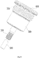
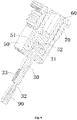
Fig. 8 shows the assembly diagram of the connection assembly in the connector shown inFig. 1 ; -
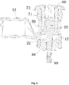
Fig. 9 shows a sectional view of the connection assembly shown inFig. 8 ; and -
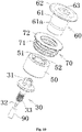
Fig. 10 shows an exploded schematic of the connection assembly shown inFig. 8 . - Exemplary embodiments of the present disclosure will be described hereinafter in detail with reference to the attached drawings, wherein the like reference numerals refer to the like elements. The present disclosure may, however, be embodied in many different forms and should not be construed as being limited to the embodiment set forth herein; rather, these embodiments are provided so that the present disclosure will be thorough and complete, and will fully convey the concept of the disclosure to those skilled in the art.
- In the following detailed description, for purposes of explanation, numerous specific details are set forth in order to provide a thorough understanding of the disclosed embodiments. It will be apparent, however, that one or more embodiments may be practiced without these specific details. In other instances, well-known structures and devices are schematically shown in order to simplify the drawing.
- According to a general concept of the present invention, there is provided a connection assembly for connecting a high-voltage cable, the connection assembly comprises: a threaded fastener for fixedly connecting the high-voltage cable to the mating connection part, wherein the threaded fastener comprises an insulation member; and a conductive plug connected with the insulation member so that the threaded fastener can be tightened or loosened by rotating the conductive plug.
- According to another general technical concept of the present invention, there is provided a connector, which comprises: a conductive housing with a mounting hole; an inner insulator installed in the conductive housing; a terminal arranged on the inner insulator; a mating thread connector arranged on the inner insulator; and the connection assembly, which enters the conductive housing through the mounting hole and is connected with the mating threaded connecting member for electrically connecting the terminal to the high-voltage cable.
-
Fig. 1 shows an illustrative perspective view of a connector according to an exemplary embodiment of the present invention.Figure 2 shows a sectional view of the connector shown inFigure 1 .Fig. 3 shows an illustrative perspective view of a connector according to an exemplary embodiment of the present invention, wherein theconductive housing 100 is removed.Fig. 7 shows an exploded schematic diagram of a connector according to an exemplary embodiment of the present invention. - As shown in
Figs. 1-3 andFig. 7 , in the illustrated embodiment, the connector mainly includes: aconductive housing 100, aninternal insulator 200, aterminal 20, a threaded connectingmember 30, a mating threaded connectingmember 40, aconductive plug 60, anelastic sealing sleeve 70 and aninsulation member 50. Theconductive housing 100 has amounting hole 101. Theinner insulator 200 is mounted in theconductive housing 100. Theterminal 20 is provided on theinner insulator 200. Theinner insulator 200 is used to hold theterminal 20 and electrically isolate theterminal 20 from theconductive housing 100. -
Fig. 8 shows the assembly diagram of the connection assembly in the connector shown inFig. 1 ;Fig. 9 shows a sectional view of the connection assembly shown inFig. 8 ;Fig. 10 shows an exploded schematic of the connection assembly shown inFig. 8 . - As shown in
Figs. 1-3 andFigs. 7-10 , in the illustrated embodiment, the threaded connectingmember 30, theconductive plug 60 and theinsulation member 50 form a connection assembly. The connection assembly enters theconductive housing 100 through the mountinghole 101 of theconductive housing 100. The threaded connectingmember 30 of the connection assembly is threaded with the mating threaded connectingmember 40 to connect the terminal 20 to thecable terminal 10. In the illustrated embodiment, oneend 11 of thecable terminal 10 is crimped to the conductor of thehigh voltage cable 1, and theother end 12 is connected to oneend 22 of the terminal 20 of the connector. In this way, theterminal 20 of the connector is connected to thehigh voltage cable 1. Although not shown, the connector also includes a shield connecting member installed in theconductive housing 100 for electrically connecting the shielding layer of thehigh voltage cable 1 to theconductive housing 100. For example, the aforementioned shield connecting member may be a conductive ring sheathed on the shielding layer of the high-voltage cable 1, the conductive ring has a conductive spring, and the conductive spring is in contact with the inner wall surface of theconductive housing 100. If there is a waterproof requirement, the connector also includes a sealing ring arranged between theconductive housing 100 and the high-voltage cable to seal the mating interface between them. - As shown in
Figs. 1-3 andFigs. 7-10 , in the illustrated embodiment, theconductive plug 60 is arranged in the mountinghole 101 to block the mountinghole 101 to realize the electromagnetic shielding function. Theelastic sealing sleeve 70 is sleeved on theconductive plug 60 and seals the gap between theconductive plug 60 and theconductive housing 100 to achieve the waterproof function. Please note that if the installation environment has no waterproof requirements, theelastic sealing sleeve 70 can be omitted. Theinsulation member 50 is engaged between theconductive plug 60 and the threaded connectingmember 30 and electrically isolates theconductive plug 60 from the threaded connectingmember 30, so that the threaded connectingmembers conductive plug 60. In the illustrated embodiment, the threaded connectingmember 30 is conductive, and theinsulation member 50 can prevent the operator from contacting the conductive threaded connectingmember 30. - As shown in
Figs. 1-3 and7 , in the illustrated embodiment, in order to realize the electromagnetic shielding function, the size of the gap between theconductive plug 60 and theconductive housing 100 is set to prevent electromagnetic waves from being leaked to the outside of theconductive housing 100 through the gap. The size of the gap between theconductive plug 60 and theconductive housing 100 includes two sizes, one is the width of the gap, and the other is the length of the gap. The two sizes can be reasonably set according to the wavelength of the electromagnetic wave. - As shown in
Figs. 1-3 and7 , in the illustrated embodiment, theelastic sealing sleeve 70 may be made of a common elastic material, such as rubber. Theelastic sealing sleeve 70 usually only has a waterproof function and has no conductive function. However, the present invention is not limited to this. For example, in an exemplary embodiment of the present invention, theelastic sealing sleeve 70 may be an elastic conductive seal made of an elastic conductive material, so that theconductive plug 60 can be electrically connected to theconductive housing 100 via theelastic sealing sleeve 70. In this way, the electromagnetic shielding effect of the connector can be further improved. - As shown in
Fig. 2 andFigs. 8-10 , in an exemplary embodiment of the present invention, theinsulation member 50 can be simultaneously molded on the threaded connectingmember 30 and theconductive plug 60 by injection molding. In this way, theinsulation member 50 can be engaged to the threaded connectingmember 30 and theconductive plug 60 at the same time. However, the present invention is not limited to this. For example, in another exemplary embodiment of the present invention, theinsulation member 50 may be formed separately from the threaded connectingmember 30 and theconductive plug 60 and sleeved on the threaded connectingmember 30 and theconductive plug 60. Alternatively, in another exemplary embodiment of the present invention, theinsulation member 50 may be formed on one of the threaded connectingmember 30 and theconductive plug 60 and sheathed on the other of the threaded connectingmember 30 and theconductive plug 60. - As shown in
Fig. 2 andFig. 8-10 , in the illustrated embodiment, theinsulation member 50 is formed separately from theconductive plug 60 and sheathed on theconductive plug 60. Anannular groove 61a is formed on one of the inner wall of theinsulation member 50 and the outer wall of theconductive plug 60, and an annular protrusion suitable for engagement with theannular groove 61a is formed on the other. When theinsulation member 50 is sleeved on theconductive plug 60, theannular groove 61a is engaged with the annular protrusion to prevent theconductive plug 60 from being axially separated from theinsulation member 50. - As shown in
Fig. 2 andFigs. 8-10 , in the illustrated embodiment, theinsulation member 50 includes acircumferential insulation part 51 and an intermediateconvex part 52. The intermediateconvex part 52 is located in thecircumferential insulation part 51 and connected to thecircumferential insulation part 51. Theconductive plug 60 is engaged between thecircumferential insulation part 51 and the intermediateconvex part 52 of theinsulation member 50 so that theconductive plug 60 cannot be rotated with respect to theinsulation member 50. The threaded connectingmember 30 is engaged in the intermediateconvex part 52 of theinsulation member 50 so that the threaded connectingmember 30 cannot be rotated with respect to theinsulation member 50. - As shown in
Fig. 2 andFigs. 8-10 , in the illustrated embodiment, theinsulation member 50 is molded on the threaded connectingmember 30. Theinsulation member 50 and the threaded connectingmember 30 together form a threaded fastener. - As shown in
Fig. 2 andFig. 8-10 , in the illustrated embodiment, the threaded connectingmember 30 is a bolt, the mating threaded connectingmember 40 is a nut, and anexternal thread 33 connected with the nut thread is formed on the bolt. Thehead 31 of the bolt is engaged in theinsulation member 50, and the nut is fixed to the terminal 20. The bolt passes through thecable terminal 10 and theconnector terminal 20 and is threaded with the nut to connect thecable terminal 10 and theconnector terminal 20 together. In the illustrated embodiment, the bolt can be rotated by rotating theconductive plug 60 so that the bolt can be tightened or loosened. - However, please note that the present invention is not limited to the illustrated embodiment. For example, in another exemplary embodiment of the present invention, the threaded connecting
member 30 is a nut and the mating threaded connectingmember 40 is a bolt. The nut is engaged in theinsulation member 50, and thehead 31 of the bolt is fixed to the terminal 20. The bolt passes through thecable terminal 10 and theconnector terminal 20 and is threaded with the nut to connect thecable terminal 10 and theconnector terminal 20 together. - As shown in
Figure 2 andfigures 8-10 , in the illustrated embodiment, the connector also includes aninsulation cap 90, which is sleeved on theend 32 of thebolt 30 opposite to thehead 31 to prevent the operator from contacting theend 32 of thebolt 30. In this way, electric shock accidents can be prevented. - As shown in
Fig. 2 andFigs. 8-10 , in the illustrated embodiment, ablind slot hole 63 is formed on the outer end of theconductive plug 60, which is used to engage with an external tool (not shown), so that theconductive plug 60 can be driven to rotate by the external tool. In this way, the threaded connectingmember 30 can be tightened or loosened. - As shown in
figures 1-3 and8-10 , in the illustrated embodiment, theconductive plug 60 includes acolumnar body part 61, and theelastic sealing sleeve 70 includes acylindrical body part 71. The cylindricalmain body 71 is sheathed on thecolumnar body part 61 and is radially compressed between thecolumnar body part 61 of theconductive plug 60 and the inner wall of the mountinghole 101 to seal the gap between them. - As shown in
Figs. 1-3 andFigs. 8-10 , in the illustrated embodiment, theconductive plug 60 also includes anannular brim part 62 formed at the outer end of thecolumnar body part 61, and theelastic sealing sleeve 70 also includes anannular lip part 72 formed at one end of thecylindrical body portion 71 and extending radially. Theannular lip part 72 of theelastic sealing sleeve 70 is axially compressed between theannular brim part 62 of theconductive plug 60 and the outer surface of theconductive housing 100 to seal the gap between them. - As shown in
Figs. 1-3 and8-10 , in the illustrated embodiment, the connector also includes anelastic sealing ring 80 arranged at the bottom of theconductive housing 100. When theconductive housing 100 of the connector is installed on a housing of an electrical equipment, theelastic sealing ring 80 is compressed between theconductive housing 100 of the connector and the housing of the electrical equipment to seal the mating interface between them. -
Fig. 4 shows a three-dimensional schematic view of the connector shown inFig. 3 when viewed from one direction, wherein theinner insulator 200 is removed.Fig. 5 shows a schematic stereoscopic view of the connector shown inFig. 3 when viewed from another direction, wherein theinner insulator 200 is removed.Figure 6 shows a sectional view of the connector shown inFigures 4 and5 . - As shown in
Figs. 4 to 6 , in the illustrated embodiment, theterminal 20 of the connector is suitable for electrical connection with a bus bar (not shown). Oneend 11 of thecable terminal 10 is cylindrical and crimped to the high-voltage cable 1. Theother end 12 of thecable terminal 10 is electrically connected with oneend 22 of theconnector terminal 20. Theother end 21 of the terminal 20 of the connector is plate-shaped and suitable for connection to the bus bar. In the illustrated embodiment, theother end 12 of thecable terminal 10 and oneend 22 of theconnector terminal 20 are stacked together and can be connected together through the threaded connectingmember 30 and the mating threaded connectingmember 40. - As shown in
Figs. 4 to 6 , in the illustrated embodiment, a slot is formed at oneend 22 of the terminal 20 of the connector, and the mating threaded connectingmember 40 is positioned in the slot at oneend 22 of the terminal 20 so that the mating threaded connectingmember 40 cannot be rotated relative to the terminal 20. - As shown in
Figs. 1 to 3 , in an exemplary embodiment of the present invention, a connector assembly is also disclosed. The connector assembly mainly includes the above connector and cable assembly. The cable assembly includes a high-voltage cable 1 and acable terminal 10 electrically connected to a conductor of the high-voltage cable 1. The terminal 20 of the connector is electrically connected with thecable terminal 10. - As shown in
Fig. 2 andFigs. 8-10 , in an exemplary embodiment of the present invention, a connection assembly for connecting a high-voltage cable 1 is also disclosed. The connection assembly mainly includes: a threadedfastener conductive plug 60. The threadedfastener voltage cable 1 to the mating connection part (for example, terminal 20 in the figure). The threadedfastener insulation member 50 and a conductive threaded connectingmember 30. Theconductive plug 60 is connected with theinsulation member 50 so that the threadedfastener conductive plug 50. In the illustrated embodiment, theinsulation member 50 is engaged between theconductive plug 60 and the threaded connectingmember 30 and electrically isolates theconductive plug 60 from the threaded connectingmember 30. - As shown in
Fig. 2 andFigs. 8-10 , in the illustrated embodiment, theinsulation member 50 includes a cylindricalcircumferential insulation part 51, which is arranged around theconductive plug 60 and is suitable to be sheathed on theconductive plug 60 to increase the creepage distance between the threaded connectingmember 30 and theconductive plug 60. In the illustrated embodiment, thecircumferential insulation part 51 also axially limits the axial position of theelastic seal 70 to prevent theelastic seal 70 from being moved downward. - It should be appreciated for those skilled in this art that the above embodiments are intended to be illustrated, and not restrictive. For example, many modifications may be made to the above embodiments by those skilled in this art, and various features described in different embodiments may be freely combined with each other without conflicting in configuration or principle.
- Although several exemplary embodiments have been shown and described, it would be appreciated by those skilled in the art that various changes or modifications may be made in these embodiments without departing from the principles and spirit of the disclosure, the scope of which is defined in the claims and their equivalents.
- As used herein, an element recited in the singular and proceeded with the word "a" or "an" should be understood as not excluding plural of said elements or steps, unless such exclusion is explicitly stated. Furthermore, references to "one embodiment" of the present invention are not intended to be interpreted as excluding the existence of additional embodiments that also incorporate the recited features. Moreover, unless explicitly stated to the contrary, embodiments "comprising" or "having" an element or a plurality of elements having a particular property may include additional such elements not having that property.
Claims (15)
- A connection assembly for connecting a high-voltage cable (1), characterized in that the connection assembly comprising:a threaded fastener (30, 50) for fixedly connecting the high-voltage cable (1) to a mating connection part, the threaded fastener comprising an insulation member (50); anda conductive plug (60) connected with the insulation member (50) to allow the threaded fastener (30, 50) to be tightened or loosened by rotating the conductive plug (60).
- The connection assembly according to claim 1, characterized in thatthe threaded fastener (30, 50) comprises a conductive threaded connecting member (30);the insulation member (50) is engaged between the conductive plug (60) and the threaded connecting member (30) and electrically isolating the conductive plug (60) from the threaded connecting member (30);the insulation member (50) comprises a circumferential insulation part (51), which is arranged around the conductive plug (60) to increase a creepage distance between the threaded connecting member (30) and the conductive plug (60).
- The connection assembly according to claim 2, characterized in thatthe insulation member (50) and the conductive plug (60) are separately molded and sleeved on the conductive plug (60);an annular groove (61a) is formed on one of the inner wall of the insulation member (50) and the outer wall of the conductive plug (60), and an annular protrusion suitable for engagement with the annular groove (61a) is formed on the other.
- The connection assembly according to claim 1, characterized in thatthe insulation member (50) further comprises an intermediate convex part (52), and the circumferential insulation part (51) surrounds the intermediate convex part (52) and is connected to the intermediate convex part (52),the conductive plug (60) is engaged between the circumferential insulation part (51) and the intermediate convex part (52) of the insulation member (50), so as to prevent the conductive plug (60) from being rotated with respect to the insulation member (50),the threaded connecting member (30) is engaged in the intermediate convex part (52) of the insulation member (50), so as to prevent the threaded connecting member (30) from being rotated with respect to the insulation member (50).
- The connection assembly according to claim 1, characterized in thatthe threaded connecting member (30) is a bolt, and the head (31) of the bolt is engaged into the insulation member (50); andthe connection assembly further comprises an insulation cap (90) which is sleeved on the end (32) of the bolt opposite to the head (31) to prevent the end (32) of the bolt from being contacted by a finger.
- The connection assembly according to claim 1, characterized in that
a blind slot hole (63) is formed in the outer end of the conductive plug (60), and the blind slot hole (63) is used to engage with an external tool for driving the conductive plug (60) to rotate. - The connection assembly according to any one of claims 1 to 6, characterized by further comprising:
an elastic sealing sleeve (70) sleeved on the conductive plug (60) to seal a gap between the conductive plug (60) and a conductive housing (100). - A connector, characterized by comprising:a conductive housing (100) having a mounting hole (101);an inner insulator (200) mounted in the conductive housing (100);a terminal (20) provided on the inner insulator (200);a mating threaded connecting member (40) provided on the inner insulator (200); andthe connection assembly according to any one of claims 1 to 7,wherein the connection assembly enters the conductive housing (100) through the mounting hole (101) and is connected with the mating threaded connecting member (40) for electrically connecting the terminal (20) to a high-voltage cable (1).
- The connector according to claim 8, characterized in thatthe conductive plug (60) of the connection assembly is arranged in the mounting hole (101) for blocking the mounting hole (101);the elastic sealing sleeve (70) of the connection assembly is sleeved on the conductive plug (60) to seal a gap between the conductive plug (60) and the conductive housing (100).
- The connector according to claim 9, characterized in that
the size of the gap between the conductive plug (60) and the conductive housing (100) is set to prevent electromagnetic waves from being leaked to the outside of the conductive housing (100) through the gap. - The connector according to claim 9, characterized in that
the elastic sealing sleeve (70) is an elastic conductive seal made of an elastic conductive material, and the conductive plug (60) is electrically connected to the conductive housing (100) through the elastic sealing sleeve (70). - The connector according to claim 8, characterized in that
a slot is formed on the terminal (20), and the mating threaded connecting member (40) is positioned in the slot of the terminal (20) to prevent the mating threaded connecting member (40) from being rotated with respect to the terminal (20). - The connector according to any one of claims 8-12, characterized in thatthe conductive plug (60) comprises a columnar body part (61), and the elastic sealing sleeve (70) comprises a cylindrical body part (71);the cylindrical body part (71) is sleeved on the columnar body part (61) and is radially compressed between the columnar body part (61) of the conductive plug (60) and the inner wall of the mounting hole (101) to seal the gap between them.
- The connector according to claim 13, characterized in thatthe conductive plug (60) further comprises an annular brim part (62) formed at the outer end of the columnar body part (61), and the elastic sealing sleeve (70) further comprises a radially extending annular lip part (72) formed at one end of the cylindrical body part (71);the annular lip part (72) is axially compressed between the annular brim part (62) of the conductive plug (60) and the outer surface of the conductive housing (100) to seal the gap between them.
- A connector assembly, characterized by comprising:the connector according to any one of claims 8 to 14; anda cable assembly comprising a cable (1) and a cable terminal (10) connected with the cable (1);wherein the cable terminal (10) is arranged in the conductive housing (100) and is electrically connected with the terminal (20) of the connector.
Applications Claiming Priority (1)
| Application Number | Priority Date | Filing Date | Title |
|---|---|---|---|
| CN202110820871.8A CN115642414A (en) | 2021-07-20 | 2021-07-20 | Connection components, connectors and connector components |
Publications (2)
| Publication Number | Publication Date |
|---|---|
| EP4123838A1 true EP4123838A1 (en) | 2023-01-25 |
| EP4123838B1 EP4123838B1 (en) | 2025-03-05 |
Family
ID=82655147
Family Applications (1)
| Application Number | Title | Priority Date | Filing Date |
|---|---|---|---|
| EP22185590.1A Active EP4123838B1 (en) | 2021-07-20 | 2022-07-19 | Connection assembly, connector, and connector assembly |
Country Status (5)
| Country | Link |
|---|---|
| US (1) | US12288953B2 (en) |
| EP (1) | EP4123838B1 (en) |
| JP (1) | JP2023016020A (en) |
| KR (1) | KR20230014071A (en) |
| CN (1) | CN115642414A (en) |
Cited By (2)
| Publication number | Priority date | Publication date | Assignee | Title |
|---|---|---|---|---|
| IT202300004809A1 (en) * | 2023-03-14 | 2024-09-14 | Te Connectivity Italia Distribution Srl | CONNECTOR GROUP FOR BATTERY MODULES OF AN ELECTRIC VEHICLE |
| CN118920159A (en) * | 2024-08-26 | 2024-11-08 | 苏州冠韵威电子技术有限公司 | Electrical connection assembly for semiconductor device |
Families Citing this family (3)
| Publication number | Priority date | Publication date | Assignee | Title |
|---|---|---|---|---|
| DE102021203915A1 (en) * | 2021-04-20 | 2022-10-20 | Robert Bosch Gesellschaft mit beschränkter Haftung | Connection arrangement, in particular for use in electric vehicles or hybrid vehicles |
| CN115642414A (en) * | 2021-07-20 | 2023-01-24 | 泰科电子(上海)有限公司 | Connection components, connectors and connector components |
| DE102021123635A1 (en) * | 2021-09-13 | 2023-03-16 | Te Connectivity Germany Gmbh | High current connection turnbuckle device and high current electrical connector and high current line connector |
Citations (3)
| Publication number | Priority date | Publication date | Assignee | Title |
|---|---|---|---|---|
| DE8520278U1 (en) * | 1985-07-13 | 1985-09-19 | Varta Batterie Ag, 3000 Hannover | Cable connector for connection to the end poles of electrical accumulators |
| EP0822614A1 (en) * | 1996-07-29 | 1998-02-04 | Techmo S.A. | Cable connector especially for pole connections and intercell connection cables |
| CN206650178U (en) * | 2017-03-16 | 2017-11-17 | 深圳市沃尔核材股份有限公司 | The connector construction of cable |
Family Cites Families (16)
| Publication number | Priority date | Publication date | Assignee | Title |
|---|---|---|---|---|
| US3836941A (en) * | 1973-07-05 | 1974-09-17 | Thomas & Betts Corp | Electrical connector with resilient pressure pad |
| US9040845B2 (en) * | 2010-12-27 | 2015-05-26 | Yazaki Corporation | Shielding structure for wire harness |
| US9929477B2 (en) * | 2015-04-30 | 2018-03-27 | Ilsco Corporation | Torque limited screw for electrical connector |
| CN105703113B (en) * | 2016-03-08 | 2018-01-16 | 浙江安美科技有限公司 | A kind of fast joint |
| CN106898887B (en) * | 2017-03-16 | 2024-11-29 | 深圳市沃尔新能源电气科技股份有限公司 | Connector structure of cable |
| CN206610923U (en) * | 2017-03-19 | 2017-11-03 | 温州市金城电子开关厂 | A kind of Wiring terminal |
| CN207994252U (en) * | 2018-03-30 | 2018-10-19 | 深圳市沃尔新能源电气科技股份有限公司 | Plug-assembly |
| CN208622996U (en) * | 2018-06-12 | 2019-03-19 | 宁德时代新能源科技股份有限公司 | Connector |
| CN208336661U (en) * | 2018-06-29 | 2019-01-04 | 宁德时代新能源科技股份有限公司 | Connector |
| JP7127507B2 (en) * | 2018-11-20 | 2022-08-30 | 住友電装株式会社 | connector |
| CN109524835A (en) * | 2018-12-05 | 2019-03-26 | 乐清市八达光电科技股份有限公司 | A kind of high current connector |
| CN209200253U (en) * | 2018-12-05 | 2019-08-02 | 乐清市八达光电科技股份有限公司 | A high current connector |
| CN211929807U (en) * | 2020-03-31 | 2020-11-13 | 世强先进(深圳)科技股份有限公司 | Communication equipment filter and communication equipment filter port electromagnetic shielding protection device |
| CN215732269U (en) * | 2021-07-20 | 2022-02-01 | 泰科电子(上海)有限公司 | Connecting assembly, connector and connector assembly |
| CN115642414A (en) * | 2021-07-20 | 2023-01-24 | 泰科电子(上海)有限公司 | Connection components, connectors and connector components |
| EP4243213A1 (en) * | 2022-03-09 | 2023-09-13 | Tyco Electronics (Shanghai) Co., Ltd. | Connector and connector assembly |
-
2021
- 2021-07-20 CN CN202110820871.8A patent/CN115642414A/en active Pending
-
2022
- 2022-07-11 US US17/861,292 patent/US12288953B2/en active Active
- 2022-07-15 JP JP2022113761A patent/JP2023016020A/en active Pending
- 2022-07-19 EP EP22185590.1A patent/EP4123838B1/en active Active
- 2022-07-19 KR KR1020220088659A patent/KR20230014071A/en active Pending
Patent Citations (3)
| Publication number | Priority date | Publication date | Assignee | Title |
|---|---|---|---|---|
| DE8520278U1 (en) * | 1985-07-13 | 1985-09-19 | Varta Batterie Ag, 3000 Hannover | Cable connector for connection to the end poles of electrical accumulators |
| EP0822614A1 (en) * | 1996-07-29 | 1998-02-04 | Techmo S.A. | Cable connector especially for pole connections and intercell connection cables |
| CN206650178U (en) * | 2017-03-16 | 2017-11-17 | 深圳市沃尔核材股份有限公司 | The connector construction of cable |
Cited By (3)
| Publication number | Priority date | Publication date | Assignee | Title |
|---|---|---|---|---|
| IT202300004809A1 (en) * | 2023-03-14 | 2024-09-14 | Te Connectivity Italia Distribution Srl | CONNECTOR GROUP FOR BATTERY MODULES OF AN ELECTRIC VEHICLE |
| EP4432476A1 (en) * | 2023-03-14 | 2024-09-18 | TE Connectivity Italia Distribution S.r.l. | Connector assembly for battery modules of an electric vehicle |
| CN118920159A (en) * | 2024-08-26 | 2024-11-08 | 苏州冠韵威电子技术有限公司 | Electrical connection assembly for semiconductor device |
Also Published As
| Publication number | Publication date |
|---|---|
| EP4123838B1 (en) | 2025-03-05 |
| US20230028765A1 (en) | 2023-01-26 |
| US12288953B2 (en) | 2025-04-29 |
| JP2023016020A (en) | 2023-02-01 |
| CN115642414A (en) | 2023-01-24 |
| KR20230014071A (en) | 2023-01-27 |
Similar Documents
| Publication | Publication Date | Title |
|---|---|---|
| US12288953B2 (en) | Connection assembly, connector, and connector assembly | |
| US8992249B2 (en) | Shielded connector | |
| CN102781189B (en) | For seal cover and the manufacture method of onboard electrical device | |
| US8408927B2 (en) | Floating connector with flexible conductive member | |
| US11804675B2 (en) | Plug connector, receptacle connector and connector assembly | |
| JP5799965B2 (en) | Floating connector | |
| US20110130048A1 (en) | Plug connector and plug connector set | |
| CN107453158B (en) | Wire harness connector and cable connection method | |
| US3275737A (en) | Coaxial cable terminating means | |
| EP2666673B1 (en) | Wire harness shield structure | |
| EP2937946A1 (en) | Connector, mating connector and connector combination | |
| EP3582333B1 (en) | Terminal | |
| US12374835B2 (en) | Connectors and connector assembly | |
| EP4207508A1 (en) | Connector housing assembly, connector and connector assembly | |
| CN118676694B (en) | Irradiation-resistant direct push-pull self-locking sealing connector | |
| CN215732269U (en) | Connecting assembly, connector and connector assembly | |
| US12224528B2 (en) | Connector and connector assembly | |
| KR20230117053A (en) | Connection assembly, connector, and connector assembly | |
| KR20230117050A (en) | Conductive terminal, terminal assembly, connector and connector assembly | |
| KR102769070B1 (en) | High voltage connector | |
| IT8953395U1 (en) | INHERENTLY SAFE ELECTRICAL CONNECTOR | |
| EP4343973A1 (en) | Connector assembly and electrical connection assembly | |
| KR101314843B1 (en) | SMA connector | |
| US20230039294A1 (en) | Connector connection structure | |
| CN113471761B (en) | Plug and socket connectors |
Legal Events
| Date | Code | Title | Description |
|---|---|---|---|
| PUAI | Public reference made under article 153(3) epc to a published international application that has entered the european phase |
Free format text: ORIGINAL CODE: 0009012 |
|
| STAA | Information on the status of an ep patent application or granted ep patent |
Free format text: STATUS: THE APPLICATION HAS BEEN PUBLISHED |
|
| AK | Designated contracting states |
Kind code of ref document: A1 Designated state(s): AL AT BE BG CH CY CZ DE DK EE ES FI FR GB GR HR HU IE IS IT LI LT LU LV MC MK MT NL NO PL PT RO RS SE SI SK SM TR |
|
| STAA | Information on the status of an ep patent application or granted ep patent |
Free format text: STATUS: REQUEST FOR EXAMINATION WAS MADE |
|
| 17P | Request for examination filed |
Effective date: 20230717 |
|
| RBV | Designated contracting states (corrected) |
Designated state(s): AL AT BE BG CH CY CZ DE DK EE ES FI FR GB GR HR HU IE IS IT LI LT LU LV MC MK MT NL NO PL PT RO RS SE SI SK SM TR |
|
| GRAP | Despatch of communication of intention to grant a patent |
Free format text: ORIGINAL CODE: EPIDOSNIGR1 |
|
| STAA | Information on the status of an ep patent application or granted ep patent |
Free format text: STATUS: GRANT OF PATENT IS INTENDED |
|
| INTG | Intention to grant announced |
Effective date: 20241121 |
|
| GRAS | Grant fee paid |
Free format text: ORIGINAL CODE: EPIDOSNIGR3 |
|
| GRAA | (expected) grant |
Free format text: ORIGINAL CODE: 0009210 |
|
| STAA | Information on the status of an ep patent application or granted ep patent |
Free format text: STATUS: THE PATENT HAS BEEN GRANTED |
|
| P01 | Opt-out of the competence of the unified patent court (upc) registered |
Free format text: CASE NUMBER: APP_673/2025 Effective date: 20250108 |
|
| AK | Designated contracting states |
Kind code of ref document: B1 Designated state(s): AL AT BE BG CH CY CZ DE DK EE ES FI FR GB GR HR HU IE IS IT LI LT LU LV MC MK MT NL NO PL PT RO RS SE SI SK SM TR |
|
| REG | Reference to a national code |
Ref country code: GB Ref legal event code: FG4D |
|
| REG | Reference to a national code |
Ref country code: CH Ref legal event code: EP |
|
| REG | Reference to a national code |
Ref country code: IE Ref legal event code: FG4D |
|
| REG | Reference to a national code |
Ref country code: DE Ref legal event code: R096 Ref document number: 602022011341 Country of ref document: DE |
|
| REG | Reference to a national code |
Ref country code: NL Ref legal event code: FP |
|
| REG | Reference to a national code |
Ref country code: SE Ref legal event code: TRGR |
|
| PG25 | Lapsed in a contracting state [announced via postgrant information from national office to epo] |
Ref country code: RS Free format text: LAPSE BECAUSE OF FAILURE TO SUBMIT A TRANSLATION OF THE DESCRIPTION OR TO PAY THE FEE WITHIN THE PRESCRIBED TIME-LIMIT Effective date: 20250605 |
|
| PG25 | Lapsed in a contracting state [announced via postgrant information from national office to epo] |
Ref country code: FI Free format text: LAPSE BECAUSE OF FAILURE TO SUBMIT A TRANSLATION OF THE DESCRIPTION OR TO PAY THE FEE WITHIN THE PRESCRIBED TIME-LIMIT Effective date: 20250305 |
|
| PG25 | Lapsed in a contracting state [announced via postgrant information from national office to epo] |
Ref country code: ES Free format text: LAPSE BECAUSE OF FAILURE TO SUBMIT A TRANSLATION OF THE DESCRIPTION OR TO PAY THE FEE WITHIN THE PRESCRIBED TIME-LIMIT Effective date: 20250305 |
|
| REG | Reference to a national code |
Ref country code: LT Ref legal event code: MG9D |
|
| PG25 | Lapsed in a contracting state [announced via postgrant information from national office to epo] |
Ref country code: NO Free format text: LAPSE BECAUSE OF FAILURE TO SUBMIT A TRANSLATION OF THE DESCRIPTION OR TO PAY THE FEE WITHIN THE PRESCRIBED TIME-LIMIT Effective date: 20250605 |
|
| PGFP | Annual fee paid to national office [announced via postgrant information from national office to epo] |
Ref country code: NL Payment date: 20250613 Year of fee payment: 4 |
|
| PG25 | Lapsed in a contracting state [announced via postgrant information from national office to epo] |
Ref country code: HR Free format text: LAPSE BECAUSE OF FAILURE TO SUBMIT A TRANSLATION OF THE DESCRIPTION OR TO PAY THE FEE WITHIN THE PRESCRIBED TIME-LIMIT Effective date: 20250305 |
|
| PG25 | Lapsed in a contracting state [announced via postgrant information from national office to epo] |
Ref country code: LV Free format text: LAPSE BECAUSE OF FAILURE TO SUBMIT A TRANSLATION OF THE DESCRIPTION OR TO PAY THE FEE WITHIN THE PRESCRIBED TIME-LIMIT Effective date: 20250305 |
|
| PGFP | Annual fee paid to national office [announced via postgrant information from national office to epo] |
Ref country code: FR Payment date: 20250610 Year of fee payment: 4 |
|
| PG25 | Lapsed in a contracting state [announced via postgrant information from national office to epo] |
Ref country code: GR Free format text: LAPSE BECAUSE OF FAILURE TO SUBMIT A TRANSLATION OF THE DESCRIPTION OR TO PAY THE FEE WITHIN THE PRESCRIBED TIME-LIMIT Effective date: 20250606 Ref country code: BG Free format text: LAPSE BECAUSE OF FAILURE TO SUBMIT A TRANSLATION OF THE DESCRIPTION OR TO PAY THE FEE WITHIN THE PRESCRIBED TIME-LIMIT Effective date: 20250305 |
|
| PGFP | Annual fee paid to national office [announced via postgrant information from national office to epo] |
Ref country code: SE Payment date: 20250610 Year of fee payment: 4 |
|
| PG25 | Lapsed in a contracting state [announced via postgrant information from national office to epo] |
Ref country code: SM Free format text: LAPSE BECAUSE OF FAILURE TO SUBMIT A TRANSLATION OF THE DESCRIPTION OR TO PAY THE FEE WITHIN THE PRESCRIBED TIME-LIMIT Effective date: 20250305 |
|
| PG25 | Lapsed in a contracting state [announced via postgrant information from national office to epo] |
Ref country code: PT Free format text: LAPSE BECAUSE OF FAILURE TO SUBMIT A TRANSLATION OF THE DESCRIPTION OR TO PAY THE FEE WITHIN THE PRESCRIBED TIME-LIMIT Effective date: 20250707 |
|
| PGFP | Annual fee paid to national office [announced via postgrant information from national office to epo] |
Ref country code: DE Payment date: 20250604 Year of fee payment: 4 |
|
| PG25 | Lapsed in a contracting state [announced via postgrant information from national office to epo] |
Ref country code: PL Free format text: LAPSE BECAUSE OF FAILURE TO SUBMIT A TRANSLATION OF THE DESCRIPTION OR TO PAY THE FEE WITHIN THE PRESCRIBED TIME-LIMIT Effective date: 20250305 |
|
| PGFP | Annual fee paid to national office [announced via postgrant information from national office to epo] |
Ref country code: IT Payment date: 20250731 Year of fee payment: 4 |
|
| PGFP | Annual fee paid to national office [announced via postgrant information from national office to epo] |
Ref country code: AT Payment date: 20251020 Year of fee payment: 4 |
|
| PG25 | Lapsed in a contracting state [announced via postgrant information from national office to epo] |
Ref country code: EE Free format text: LAPSE BECAUSE OF FAILURE TO SUBMIT A TRANSLATION OF THE DESCRIPTION OR TO PAY THE FEE WITHIN THE PRESCRIBED TIME-LIMIT Effective date: 20250305 |
|
| PGFP | Annual fee paid to national office [announced via postgrant information from national office to epo] |
Ref country code: CZ Payment date: 20250701 Year of fee payment: 4 |
|
| PG25 | Lapsed in a contracting state [announced via postgrant information from national office to epo] |
Ref country code: RO Free format text: LAPSE BECAUSE OF FAILURE TO SUBMIT A TRANSLATION OF THE DESCRIPTION OR TO PAY THE FEE WITHIN THE PRESCRIBED TIME-LIMIT Effective date: 20250305 |
|
| PG25 | Lapsed in a contracting state [announced via postgrant information from national office to epo] |
Ref country code: SK Free format text: LAPSE BECAUSE OF FAILURE TO SUBMIT A TRANSLATION OF THE DESCRIPTION OR TO PAY THE FEE WITHIN THE PRESCRIBED TIME-LIMIT Effective date: 20250305 |
|
| PG25 | Lapsed in a contracting state [announced via postgrant information from national office to epo] |
Ref country code: IS Free format text: LAPSE BECAUSE OF FAILURE TO SUBMIT A TRANSLATION OF THE DESCRIPTION OR TO PAY THE FEE WITHIN THE PRESCRIBED TIME-LIMIT Effective date: 20250705 |
|
| REG | Reference to a national code |
Ref country code: DE Ref legal event code: R097 Ref document number: 602022011341 Country of ref document: DE |
|
| PLBE | No opposition filed within time limit |
Free format text: ORIGINAL CODE: 0009261 |
|
| STAA | Information on the status of an ep patent application or granted ep patent |
Free format text: STATUS: NO OPPOSITION FILED WITHIN TIME LIMIT |
|
| PG25 | Lapsed in a contracting state [announced via postgrant information from national office to epo] |
Ref country code: DK Free format text: LAPSE BECAUSE OF FAILURE TO SUBMIT A TRANSLATION OF THE DESCRIPTION OR TO PAY THE FEE WITHIN THE PRESCRIBED TIME-LIMIT Effective date: 20250305 |
|
| REG | Reference to a national code |
Ref country code: CH Ref legal event code: L10 Free format text: ST27 STATUS EVENT CODE: U-0-0-L10-L00 (AS PROVIDED BY THE NATIONAL OFFICE) Effective date: 20260114 |
|
| 26N | No opposition filed |
Effective date: 20251208 |
|
| REG | Reference to a national code |
Ref country code: CH Ref legal event code: H13 Free format text: ST27 STATUS EVENT CODE: U-0-0-H10-H13 (AS PROVIDED BY THE NATIONAL OFFICE) Effective date: 20260224 |
|
| PG25 | Lapsed in a contracting state [announced via postgrant information from national office to epo] |
Ref country code: LU Free format text: LAPSE BECAUSE OF NON-PAYMENT OF DUE FEES Effective date: 20250719 |
|
| REG | Reference to a national code |
Ref country code: BE Ref legal event code: MM Effective date: 20250731 |
|
| PG25 | Lapsed in a contracting state [announced via postgrant information from national office to epo] |
Ref country code: BE Free format text: LAPSE BECAUSE OF NON-PAYMENT OF DUE FEES Effective date: 20250731 |
|
| PG25 | Lapsed in a contracting state [announced via postgrant information from national office to epo] |
Ref country code: CH Free format text: LAPSE BECAUSE OF NON-PAYMENT OF DUE FEES Effective date: 20250731 |