EP4123767A2 - Fuel cell temperature management device - Google Patents
Fuel cell temperature management device Download PDFInfo
- Publication number
- EP4123767A2 EP4123767A2 EP22178416.8A EP22178416A EP4123767A2 EP 4123767 A2 EP4123767 A2 EP 4123767A2 EP 22178416 A EP22178416 A EP 22178416A EP 4123767 A2 EP4123767 A2 EP 4123767A2
- Authority
- EP
- European Patent Office
- Prior art keywords
- cooling water
- fuel cell
- temperature
- cell stack
- heater
- Prior art date
- Legal status (The legal status is an assumption and is not a legal conclusion. Google has not performed a legal analysis and makes no representation as to the accuracy of the status listed.)
- Granted
Links
Images




Classifications
-
- H—ELECTRICITY
- H01—ELECTRIC ELEMENTS
- H01M—PROCESSES OR MEANS, e.g. BATTERIES, FOR THE DIRECT CONVERSION OF CHEMICAL ENERGY INTO ELECTRICAL ENERGY
- H01M8/00—Fuel cells; Manufacture thereof
- H01M8/04—Auxiliary arrangements, e.g. for control of pressure or for circulation of fluids
- H01M8/04298—Processes for controlling fuel cells or fuel cell systems
- H01M8/04694—Processes for controlling fuel cells or fuel cell systems characterised by variables to be controlled
- H01M8/04746—Pressure; Flow
- H01M8/04768—Pressure; Flow of the coolant
-
- H—ELECTRICITY
- H01—ELECTRIC ELEMENTS
- H01M—PROCESSES OR MEANS, e.g. BATTERIES, FOR THE DIRECT CONVERSION OF CHEMICAL ENERGY INTO ELECTRICAL ENERGY
- H01M8/00—Fuel cells; Manufacture thereof
- H01M8/04—Auxiliary arrangements, e.g. for control of pressure or for circulation of fluids
- H01M8/04007—Auxiliary arrangements, e.g. for control of pressure or for circulation of fluids related to heat exchange
- H01M8/04029—Heat exchange using liquids
-
- B—PERFORMING OPERATIONS; TRANSPORTING
- B60—VEHICLES IN GENERAL
- B60L—PROPULSION OF ELECTRICALLY-PROPELLED VEHICLES; SUPPLYING ELECTRIC POWER FOR AUXILIARY EQUIPMENT OF ELECTRICALLY-PROPELLED VEHICLES; ELECTRODYNAMIC BRAKE SYSTEMS FOR VEHICLES IN GENERAL; MAGNETIC SUSPENSION OR LEVITATION FOR VEHICLES; MONITORING OPERATING VARIABLES OF ELECTRICALLY-PROPELLED VEHICLES; ELECTRIC SAFETY DEVICES FOR ELECTRICALLY-PROPELLED VEHICLES
- B60L58/00—Methods or circuit arrangements for monitoring or controlling batteries or fuel cells, specially adapted for electric vehicles
- B60L58/30—Methods or circuit arrangements for monitoring or controlling batteries or fuel cells, specially adapted for electric vehicles for monitoring or controlling fuel cells
- B60L58/32—Methods or circuit arrangements for monitoring or controlling batteries or fuel cells, specially adapted for electric vehicles for monitoring or controlling fuel cells for controlling the temperature of fuel cells, e.g. by controlling the electric load
- B60L58/33—Methods or circuit arrangements for monitoring or controlling batteries or fuel cells, specially adapted for electric vehicles for monitoring or controlling fuel cells for controlling the temperature of fuel cells, e.g. by controlling the electric load by cooling
-
- B—PERFORMING OPERATIONS; TRANSPORTING
- B60—VEHICLES IN GENERAL
- B60L—PROPULSION OF ELECTRICALLY-PROPELLED VEHICLES; SUPPLYING ELECTRIC POWER FOR AUXILIARY EQUIPMENT OF ELECTRICALLY-PROPELLED VEHICLES; ELECTRODYNAMIC BRAKE SYSTEMS FOR VEHICLES IN GENERAL; MAGNETIC SUSPENSION OR LEVITATION FOR VEHICLES; MONITORING OPERATING VARIABLES OF ELECTRICALLY-PROPELLED VEHICLES; ELECTRIC SAFETY DEVICES FOR ELECTRICALLY-PROPELLED VEHICLES
- B60L58/00—Methods or circuit arrangements for monitoring or controlling batteries or fuel cells, specially adapted for electric vehicles
- B60L58/30—Methods or circuit arrangements for monitoring or controlling batteries or fuel cells, specially adapted for electric vehicles for monitoring or controlling fuel cells
- B60L58/32—Methods or circuit arrangements for monitoring or controlling batteries or fuel cells, specially adapted for electric vehicles for monitoring or controlling fuel cells for controlling the temperature of fuel cells, e.g. by controlling the electric load
- B60L58/34—Methods or circuit arrangements for monitoring or controlling batteries or fuel cells, specially adapted for electric vehicles for monitoring or controlling fuel cells for controlling the temperature of fuel cells, e.g. by controlling the electric load by heating
-
- H—ELECTRICITY
- H01—ELECTRIC ELEMENTS
- H01M—PROCESSES OR MEANS, e.g. BATTERIES, FOR THE DIRECT CONVERSION OF CHEMICAL ENERGY INTO ELECTRICAL ENERGY
- H01M8/00—Fuel cells; Manufacture thereof
- H01M8/04—Auxiliary arrangements, e.g. for control of pressure or for circulation of fluids
- H01M8/04007—Auxiliary arrangements, e.g. for control of pressure or for circulation of fluids related to heat exchange
- H01M8/04037—Electrical heating
-
- H—ELECTRICITY
- H01—ELECTRIC ELEMENTS
- H01M—PROCESSES OR MEANS, e.g. BATTERIES, FOR THE DIRECT CONVERSION OF CHEMICAL ENERGY INTO ELECTRICAL ENERGY
- H01M8/00—Fuel cells; Manufacture thereof
- H01M8/04—Auxiliary arrangements, e.g. for control of pressure or for circulation of fluids
- H01M8/04007—Auxiliary arrangements, e.g. for control of pressure or for circulation of fluids related to heat exchange
- H01M8/04067—Heat exchange or temperature measuring elements, thermal insulation, e.g. heat pipes, heat pumps, fins
- H01M8/04074—Heat exchange unit structures specially adapted for fuel cell
-
- H—ELECTRICITY
- H01—ELECTRIC ELEMENTS
- H01M—PROCESSES OR MEANS, e.g. BATTERIES, FOR THE DIRECT CONVERSION OF CHEMICAL ENERGY INTO ELECTRICAL ENERGY
- H01M8/00—Fuel cells; Manufacture thereof
- H01M8/04—Auxiliary arrangements, e.g. for control of pressure or for circulation of fluids
- H01M8/04082—Arrangements for control of reactant parameters, e.g. pressure or concentration
- H01M8/04201—Reactant storage and supply, e.g. means for feeding, pipes
- H01M8/04216—Reactant storage and supply, e.g. means for feeding, pipes characterised by the choice for a specific material, e.g. carbon, hydride, absorbent
-
- H—ELECTRICITY
- H01—ELECTRIC ELEMENTS
- H01M—PROCESSES OR MEANS, e.g. BATTERIES, FOR THE DIRECT CONVERSION OF CHEMICAL ENERGY INTO ELECTRICAL ENERGY
- H01M8/00—Fuel cells; Manufacture thereof
- H01M8/04—Auxiliary arrangements, e.g. for control of pressure or for circulation of fluids
- H01M8/04298—Processes for controlling fuel cells or fuel cell systems
-
- H—ELECTRICITY
- H01—ELECTRIC ELEMENTS
- H01M—PROCESSES OR MEANS, e.g. BATTERIES, FOR THE DIRECT CONVERSION OF CHEMICAL ENERGY INTO ELECTRICAL ENERGY
- H01M8/00—Fuel cells; Manufacture thereof
- H01M8/04—Auxiliary arrangements, e.g. for control of pressure or for circulation of fluids
- H01M8/04298—Processes for controlling fuel cells or fuel cell systems
- H01M8/04313—Processes for controlling fuel cells or fuel cell systems characterised by the detection or assessment of variables; characterised by the detection or assessment of failure or abnormal function
- H01M8/0432—Temperature; Ambient temperature
- H01M8/04358—Temperature; Ambient temperature of the coolant
-
- H—ELECTRICITY
- H01—ELECTRIC ELEMENTS
- H01M—PROCESSES OR MEANS, e.g. BATTERIES, FOR THE DIRECT CONVERSION OF CHEMICAL ENERGY INTO ELECTRICAL ENERGY
- H01M8/00—Fuel cells; Manufacture thereof
- H01M8/04—Auxiliary arrangements, e.g. for control of pressure or for circulation of fluids
- H01M8/04298—Processes for controlling fuel cells or fuel cell systems
- H01M8/04694—Processes for controlling fuel cells or fuel cell systems characterised by variables to be controlled
- H01M8/04701—Temperature
-
- H—ELECTRICITY
- H01—ELECTRIC ELEMENTS
- H01M—PROCESSES OR MEANS, e.g. BATTERIES, FOR THE DIRECT CONVERSION OF CHEMICAL ENERGY INTO ELECTRICAL ENERGY
- H01M8/00—Fuel cells; Manufacture thereof
- H01M8/04—Auxiliary arrangements, e.g. for control of pressure or for circulation of fluids
- H01M8/04298—Processes for controlling fuel cells or fuel cell systems
- H01M8/04694—Processes for controlling fuel cells or fuel cell systems characterised by variables to be controlled
- H01M8/04746—Pressure; Flow
- H01M8/04776—Pressure; Flow at auxiliary devices, e.g. reformer, compressor, burner
-
- H—ELECTRICITY
- H01—ELECTRIC ELEMENTS
- H01M—PROCESSES OR MEANS, e.g. BATTERIES, FOR THE DIRECT CONVERSION OF CHEMICAL ENERGY INTO ELECTRICAL ENERGY
- H01M8/00—Fuel cells; Manufacture thereof
- H01M8/04—Auxiliary arrangements, e.g. for control of pressure or for circulation of fluids
- H01M8/04298—Processes for controlling fuel cells or fuel cell systems
- H01M8/04694—Processes for controlling fuel cells or fuel cell systems characterised by variables to be controlled
- H01M8/04955—Shut-off or shut-down of fuel cells
-
- H—ELECTRICITY
- H01—ELECTRIC ELEMENTS
- H01M—PROCESSES OR MEANS, e.g. BATTERIES, FOR THE DIRECT CONVERSION OF CHEMICAL ENERGY INTO ELECTRICAL ENERGY
- H01M8/00—Fuel cells; Manufacture thereof
- H01M8/06—Combination of fuel cells with means for production of reactants or for treatment of residues
- H01M8/0606—Combination of fuel cells with means for production of reactants or for treatment of residues with means for production of gaseous reactants
- H01M8/065—Combination of fuel cells with means for production of reactants or for treatment of residues with means for production of gaseous reactants by dissolution of metals or alloys; by dehydriding metallic substances
-
- H—ELECTRICITY
- H01—ELECTRIC ELEMENTS
- H01M—PROCESSES OR MEANS, e.g. BATTERIES, FOR THE DIRECT CONVERSION OF CHEMICAL ENERGY INTO ELECTRICAL ENERGY
- H01M2250/00—Fuel cells for particular applications; Specific features of fuel cell system
- H01M2250/20—Fuel cells in motive systems, e.g. vehicle, ship, plane
-
- Y—GENERAL TAGGING OF NEW TECHNOLOGICAL DEVELOPMENTS; GENERAL TAGGING OF CROSS-SECTIONAL TECHNOLOGIES SPANNING OVER SEVERAL SECTIONS OF THE IPC; TECHNICAL SUBJECTS COVERED BY FORMER USPC CROSS-REFERENCE ART COLLECTIONS [XRACs] AND DIGESTS
- Y02—TECHNOLOGIES OR APPLICATIONS FOR MITIGATION OR ADAPTATION AGAINST CLIMATE CHANGE
- Y02E—REDUCTION OF GREENHOUSE GAS [GHG] EMISSIONS, RELATED TO ENERGY GENERATION, TRANSMISSION OR DISTRIBUTION
- Y02E60/00—Enabling technologies; Technologies with a potential or indirect contribution to GHG emissions mitigation
- Y02E60/30—Hydrogen technology
- Y02E60/50—Fuel cells
Definitions
- the present disclosure relates to a fuel cell temperature management device for managing a temperature of a vehicle fuel cell, and a fuel cell system using the same.
- Fuel cells are devices that generate electrical energy by an electrochemical reaction between oxygen and hydrogen that is fuel gas and are spotlighted as next-generation power generation devices because the fuel cells have relatively high efficiency and do not discharge pollutants as compared to a power generation method according to the related art.
- An aspect of the present disclosure provides a fuel cell temperature management device capable of efficiently controlling the temperature of a fuel cell or a solid hydrogen storage device, and a fuel cell system using the same.
- a fuel cell temperature management device including a temperature control valve that sets a circulation path of a cooling water passing through a fuel cell stack to a first path or a second path, and a controller that controls the temperature control valve based on a temperature of the cooling water.
- the first path may include a solid hydrogen storage device that supplies hydrogen to the fuel cell stack.
- the controller may control the temperature control valve to set the circulation path to the first path when the temperature of the cooling water is higher than an upper limit of a management temperature range.
- the controller may control the temperature control valve to set the circulation path to the second path when the temperature of the cooling water is within a management temperature range.
- an exothermic reaction in the fuel cell stack, an exothermic reaction may occur when electrical energy is generated, and in the solid hydrogen storage device, an endothermic reaction may occur when the hydrogen is supplied to the fuel cell stack.
- the fuel cell temperature management device may further include a bypass valve that directs the cooling water to a heater in the circulation path and blocks the cooling water from passing through the fuel cell stack when the temperature of the cooling water is lower than a lower limit of a management temperature range.
- the controller may further control the bypass valve to direct the cooling water to the heater in the circulation path and to block the cooling water from passing through the fuel cell stack when the temperature of the cooling water is lower than the lower limit of the management temperature range, and operate the heater.
- the controller may further control the bypass valve to block the cooling water from passing through the fuel cell stack and control the temperature control valve to set the circulation path to the first path when a solid hydrogen storage device stores hydrogen.
- a fuel cell system including a fuel cell stack that receives hydrogen from a solid hydrogen storage device to generate electrical energy, a bypass valve that transfers, to one of the fuel cell stack or a heater, cooling water transferred from a cooling water pump, a temperature control valve that allows the cooling water passing through the fuel cell stack or the heater to flow into the cooling water pump or to allow the cooling water passing through the fuel cell stack or the heater to flow into the cooling water pump through the solid hydrogen storage device and a radiator, and a controller that controls the bypass valve and the temperature control valve to determine a circulation path of the cooling water based on a temperature of the cooling water passing through the fuel cell stack or the heater, the hydrogen stored in the solid hydrogen storage device, and supply of the hydrogen from the solid hydrogen storage device to the fuel cell stack.
- the controller may further form a first circulation path of the cooling water, including the cooling water pump, the bypass valve, the fuel cell stack, and the temperature control valve, based on the temperature of the cooling water passing through the fuel cell stack or the heater, when the fuel cell stack generates the electrical energy or generate a second circulation path of the cooling water, including the cooling water pump, the bypass valve, the fuel cell stack, the solid hydrogen storage device, the radiator, and the temperature control valve.
- the controller may form the first circulation path when the temperature of the cooling water passing through the fuel cell stack or the heater is within a management temperature range when the fuel cell stack generates the electrical energy.
- the controller may form the second circulation path when the temperature of the cooling water is higher than an upper limit of a management temperature range when the fuel cell stack generates the electrical energy.
- the controller may further form a circulation path of the cooling water, including the cooling water pump, the bypass valve, the heater, the solid hydrogen storage device, the radiator, and the temperature control valve, when the solid hydrogen storage device stores the hydrogen.
- the controller may further form a circulation path of the cooling water, including the bypass valve, the heater, and the temperature control valve, when the temperature of the cooling water passing through the fuel cell stack or the heater is lower than a lower limit of a management temperature range, and operate the heater.
- FIG. 1 is a view illustrating a configuration of a fuel cell temperature management device according to an embodiment of the present disclosure.
- a fuel cell temperature management device 100 may be implemented inside a vehicle.
- the fuel cell temperature management device 100 may be formed integrally with internal controllers of the vehicle or may be implemented as a separate device and connected to the controllers of the vehicle through a separate connection part.
- the fuel cell temperature management device 100 may include a controller 10, a flow path control device 20, and a temperature control device 30.
- the controller 10 may be implemented as a processor, CPU (Central Processing Unit) or SoC (System on Chip).
- the controller 10 may drive an operating system or application to control a plurality of hardware components or software components connected to the controller 10.
- the controller 10 may receive the temperature (for example, a stack outlet temperature) of a cooling water passing through a fuel cell stack 2 (illustrated in FIG. 2 ).
- the controller 10 may receive a request that occurs when hydrogen in a solid hydrogen storage device 1 (illustrated in FIG. 2 ) is stored or when the hydrogen stored in the solid hydrogen storage device 1 (illustrated in FIG. 2 ) is supplied to the fuel cell stack 2 (illustrated in FIG. 2 ).
- the controller 10 may control the flow path control device 20 and the temperature control device 30 on the basis of the stack outlet temperature (the temperature of the cooling water passing through the fuel cell stack), a hydrogen supply request (a request generated when the hydrogen stored in the solid hydrogen storage device needs to be supplied to the fuel cell stack), and a hydrogen storage request (a request generated when the solid hydrogen storage device needs to store the hydrogen).
- the flow path control device 20 may determine a circulation path of the cooling water under the control of the controller 10.
- the first path may include the cooling water pump 6, the bypass valve 21, the fuel cell stack 2, and the temperature control valve 22.
- the second path may include the cooling water pump 6, the bypass valve 21, the fuel cell stack 2, the solid hydrogen storage device 1, the radiator 31, and the temperature control valve 22.
- the flow path control device 20 may include a bypass valve 21 and a temperature control valve 22.
- the temperature control device 30 may increase or decrease the temperature of the cooling water under the control of the controller 10.
- the temperature control device 30 may include a radiator 31, a cooling fan 32, and a heater 33.
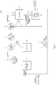
- FIG. 2 is a view illustrating a configuration of a fuel cell system using the fuel cell temperature management device according to an embodiment of the present disclosure.
- a fuel cell system 1000 may include the solid hydrogen storage device 1, the fuel cell stack 2, a solid hydrogen temperature sensor 3, a stack inlet temperature sensor 4, a stack outlet temperature sensor 5, a cooling water pump 6, the bypass valve 21, the temperature control valve 22, the radiator 31, the cooling fan 32, and the heater 33.
- the fuel cell system 1000 may further include, with respect to the cooling water pump 6, a pipe that allows the cooling water to circulate to the bypass valve 21, the stack inlet temperature sensor 4, the fuel cell stack 2, the stack outlet temperature sensor 5, the solid hydrogen storage device 1, the solid hydrogen temperature sensor 3, the radiator 31, and the temperature control valve 22, a pipe that allows the cooling water to flow to the stack outlet temperature sensor 5 through the heater 33 under control of the bypass valve 21, and a pipe that allows the cooling water passing through the stack outlet temperature sensor 5 to flow into the temperature control valve 22.
- the fuel cell system 1000 may further include a pipe for transferring the hydrogen from the solid hydrogen storage device 1 to the fuel cell stack 20.
- the solid hydrogen storage device 1 may be configured to store solid hydrogen and to supply the stored solid hydrogen to the fuel cell stack 2.
- the fuel cell stack 2 may be configured so that the hydrogen provided from the solid hydrogen storage device 1 reacts with oxygen to generate electrical energy.
- the fuel cell stack 2 may be configured to generate a high voltage as a plurality of unit cells are stacked and connected in series.
- the cooling water may prevent an increase in the temperature of the fuel cell stack 2 during power generation so that the fuel cell stack 2 is not degraded.
- the solid hydrogen temperature sensor 3 may be disposed in a pipe, through which the cooing water flows between the solid hydrogen storage device 1 and the radiator 31, to measure the temperature of the solid hydrogen storage device 1.
- the stack inlet temperature sensor 4 may be disposed in a pipe, through which the cooling water is supplied to the fuel cell stack 2, to detect the temperature of the cooling water supplied to the fuel cell stack 2.
- the stack outlet temperature sensor 5 may be disposed in a pipe, through which the cooling water passing through the fuel cell stack 2 flows, to detect the temperature of the cooling water passing through the fuel cell stack 2.
- the cooling water pump 6 may allow the cooling water to circulate through the pipe configured in the fuel cell system 1000.
- the cooling water pump 6 may allow the cooling water to circulate to the pipe connected to the bypass valve 21, the fuel cell stack 2, the solid hydrogen storage device 1, the radiator 31, and the temperature control valve 22.
- the bypass valve 21 may allow the cooling water provided from the cooling water pump 6 to flow to the stack inlet temperature sensor 4 or to the heater 33 under the control of the controller 10 (illustrated in FIG 1 ).
- the temperature control valve 22 may receive the cooling water introduced only through the stack outlet temperature sensor 5 and the cooling water further passing through the solid hydrogen storage device 1 and the radiator 31 and mix the received cooling water to provide the mixed cooling water to the cooling water pump 6.
- the temperature control valve 22 may control the amount of the cooling water introduced only through the stack outlet temperature sensor 5 and the amount of the cooling water further passing through the solid hydrogen storage device 1 and the radiator 31, to control the temperature of the cooling water provided to the cooling water pump 6, under the control of the controller 10 (illustrated in FIG. 1 ).
- controller 10 may control the bypass valve 21 so that the cooling water flows in the direction of flow path 1 or the direction of flow path 2.
- temperature control valve 22 that controls the amount of the cooling water introduced in flow path 3 and the amount of the cooling water introduced in flow path 4 to provide the cooling water to the cooling water pump 6 may be controlled by the controller 10.
- the radiator 31 may be configured to transfer heat of the cooling water to outside air (external air) to reduce the temperature of the cooling water.
- the cooling fan 32 may be configured to provide cool air to the radiator 31 so that air heated by the radiator 31 does not stagnate.
- the radiator 31 and the cooling fan 32 which are devices for reducing the temperature of the cooling water, may be configured to be operated under the control of the controller 10.
- the heater 33 may increase the temperature of the supplied cooling water.
- the cooling water having an increased temperature may flow to the pipe connected to the temperature control valve 22 and the solid hydrogen storage device 1.
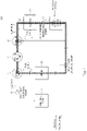
- FIG. 3 and FIG. 4 are views for describing an operation of the fuel cell system according to an embodiment of the present disclosure.
- FIG. 3 illustrates flow of the cooling water when the fuel cell stack 2 receives the hydrogen from the solid hydrogen storage device 1 to generate the electrical energy.
- the controller 10 may control the bypass valve 21 so that the cooling water provided from the cooling water pump 6 flows to the fuel cell stack 2 (to the flow path 1).
- the cooling water passing through the fuel cell stack 2 may be provided to the cooling water pump 6 again through the temperature control valve 22 (through the flow path 3).
- the controller 10 may control the bypass valve 21 so that the cooling water introduced into the bypass valve 21 flows to the flow path 1 and control the temperature control valve 22 so that the cooling water introduced from the flow path 3 is provided to the cooling water pump 6.
- the cooling water may circulate through the cooling water pump 6 to pass through the bypass valve 21, the fuel cell stack 2, and the temperature control valve 22 and to be introduced into the cooling water pump 6 again.
- the temperature of the fuel cell stack 2 that generates the electrical energy may be maintained within a management temperature range due to the circulation of the cooling water.
- the management temperature range may mean a temperature range in which the fuel cell stack 2 may normally generate the electrical energy.
- the temperature of the fuel cell stack 2 due to the heat generated by the fuel cell stack 2 cannot be maintained within the management temperature range only by the circulation of the cooling water.
- the controller 10 may control whether the flow path 4 of the temperature control valve 22 is opened and an opening amount of the temperature control valve 22 on the basis of the temperature of the cooling water detected by the stack outlet temperature sensor 5, that is, the temperature of the cooling water passing through the fuel cell stack 2.
- the controller 10 may open the flow path 4 of the temperature control valve 22 when the temperature of the cooling water detected by the stack outlet temperature sensor 5 is higher than a preset temperature and control an opening amount of the flow path 4 of the temperature control valve 22 according to an increase in the temperature of the cooling water to adjust the amount of the cooling water introduced from the flow path 4.
- the temperature control valve 22 may mix the cooling water introduced from the flow path 3 and the cooling water introduced from the flow path 4 with each other to transfer the mixed cooling water to the cooling water pump 6.
- the temperature control valve 22 may mix the cooling water introduced through the fuel cell stack 2 and the cooling water introduced through the fuel cell stack 2, the solid hydrogen storage device 1, and the radiator 31 with each other to transfer the mixed cooling water to the cooling water pump 6.
- the solid hydrogen storage device 1 has a characteristic that an endothermic reaction occurs when the stored hydrogen is supplied to the fuel cell stack 2.
- the temperature of the cooling water may be reduced.
- the radiator 31 may transfer the heat of the cooing water to the outside air to reduce the temperature of the cooling water.
- the cooling water heated by the fuel cell stack 2 when the electrical energy is generated passes through the solid hydrogen storage device 1 and the radiator 31 so that the temperature of the cooling water may be reduced.
- the temperature of the cooling water provided to the cooling water pump 6 may be lower than that when the flow path 4 is not opened.
- the temperature control valve 22 increases the opening amount of the flow path 4 under the control of the controller 10 as the temperature of the cooling water passing through the fuel cell stack 2 becomes greater, and thus may prevent the temperature of the cooling water transferred to the cooling water pump 6 from increasing.
- the temperature control valve 22 may increase the opening amount of the flow path 4 to the maximum.
- the temperature control valve 22 is controlled so that the amount of the cooing water passing through the solid hydrogen storage device 1 increases as the temperature of the cooling water passing through the fuel cell stack 2 increases, and thus even when the electrical energy is generated for a long time or an amount of the electrical energy greater than preset electrical energy is generated, the temperature of the circulating cooling water may be maintained within the management temperature range.
- FIG. 4 illustrates flow of the cooling water when the solid hydrogen storage device 1 receives and stores the hydrogen.
- Heat may be generated when the solid hydrogen storage device 1 receives the hydrogen from the outside and stores the hydrogen.
- the controller 10 may control the bypass valve 21 so that the cooling water provided from the cooling water pump 6 flows to the flow path 2 (the heater 33).
- controller 10 may open the flow path 4 of the temperature control valve 22 and may not operate the heater 33.
- the heat generated when the solid hydrogen storage device 1 stores the hydrogen may be removed by the circulating cooling water.
- the controller 10 may open the flow path 2 of the bypass valve 21, open the flow path 3 of the temperature control valve 22, and operate the heater 33.
- FIG. 5 and FIG. 6 are flowcharts for describing the operation of the fuel cell system according to the embodiment of the present disclosure.
- FIG. 5 is a flowchart for describing an operation of the fuel cell system according to an embodiment of the present disclosure when the fuel cell stack 2 receives the hydrogen from the solid hydrogen storage device 1 to generate the electrical energy.
- a cooling water temperature management method for the fuel cell system may include a first cooling water temperature comparison operation S1, a first cooling water temperature management operation S2, a second cooling water temperature comparison operation S3, a second cooling water temperature management operation S4, a third cooling water temperature management operation S5, and a fourth cooling water temperature management operation S6.
- the first cooling water temperature comparison operation S1 may include an operation of comparing the temperature (the stack outlet temperature) of the cooling water detected by the stack outlet temperature sensor 5 with the lower limit of the management temperature range.
- the first cooling water temperature management operation S2 may be performed.
- the second cooling water temperature comparison operation S3 may be performed.
- the first cooling water temperature management operation S2 may include an operation of opening the flow path 2 of the bypass valve 21, operating the heater 33, and opening the flow path 3 of the temperature control valve 22.
- the cooling water having a temperature lower than the lower limit of the management temperature range may be heated by the heater 33, and the heated cooling water may circulate in the heater 33, the temperature control valve 22, the cooling water pump 6, and the bypass valve 21. That is, the cooling water may circulate in a circulation path including the heater 33, the temperature control valve 22, the cooling water pump 6, and the bypass valve 21 at a temperature within the management temperature range.
- the second cooling water temperature comparison operation S3 may include an operation of comparing the temperature of the cooling water with the upper limit of the management temperature range.
- the second cooling water temperature management operation S4 may be performed.
- the third cooling water temperature management operation S5 may be performed.
- the second cooling water temperature management operation S4 may include an operation of opening the flow path 1 of the bypass valve 21 and opening the flow path 3 of the temperature control valve 22.
- the cooling water which has a temperature that is higher than the lower limit of the management temperature range and lower than the upper limit of the management temperature range, that is, within the management temperature range, may circulate in a circulation path including the cooling water pump 6, the bypass valve 21, the fuel cell stack 2, and the temperature control valve 22.
- a state in which the temperature of the cooing water is within the management temperature range may mean that the fuel cell stack 2 operates at a temperature at which the fuel cell stack 2 may normally generate the electrical energy.
- the third cooling water temperature management operation S5 may include an operation of opening the flow path 1 of the bypass valve 21 and opening the flow path 4 of the temperature control valve 22 to the maximum.
- the cooling water having a temperature higher than the upper limit of the management temperature range may circulate in a circulation path including the cooling water pump 6, the bypass valve 21, the fuel cell stack 2, the solid hydrogen storage device 1, the radiator 31, and the temperature control valve 22.
- the third cooling water temperature management operation S5 performed when the temperature of the cooling water is higher than the upper limit of the management temperature range may be an operation of controlling the cooling water to circulate through the solid hydrogen storage device 1 and the radiator 31 as compared to the second cooling water temperature management operation S4.
- a case in which the temperature of the cooling water is higher than the upper limit of the management temperature range may correspond to a case in which the fuel cell stack 2 generates the electrical energy for a long time or the amount of the generated electrical energy is greater than the preset amount of the electrical energy.
- the fuel cell stack 2 receives the stored hydrogen from the solid hydrogen storage device 1 to generate the electrical energy.
- the temperature of the cooling water is lowered due to the generated endothermic reaction of the solid hydrogen storage device, the heat of the cooling water is transferred to the outside air through the radiator 31, and thus the cooling water may be cooled so that the temperature of the cooling water is lower than the upper limit of the management temperature range.
- the fourth cooling water temperature management operation S6, which is performed after the third cooling water temperature management operation S5, may include an operation of operating the cooling fan 32, so that the radiator 31 may lower the temperature of the cooling water better than when the cooling fan 32 is not operated, by circulating the outside air to the radiator 31.
- FIG. 6 is a flowchart for describing an operation of the fuel cell system according to the embodiment of the present disclosure when the solid hydrogen storage device 1 receives and stores the hydrogen.
- a temperature management method for the fuel cell system when the solid hydrogen storage device stores the hydrogen may include a first path setting operation S11, a second path setting operation S12, and a cooling water cooling operation S13.
- the first path setting operation S11 may include an operation of opening the flow path 2 of the bypass valve 21.
- the first path setting operation S11 may further include an operation of detecting whether the heater 33 is operating and turning off the heater 33 so that the heater 33 is not operated.
- the second path setting operation S12 is an operation of opening the flow path 4 of the temperature control valve 22, and in the second path setting operation S12, the opening amount of the flow path 4 opened by the temperature control valve 22 may be set to the maximum.
- a path in which the cooling water circulates through the cooling water pump 6, the bypass valve 21, the heater 33 turned off, the solid hydrogen storage device 1, the radiator 31, and the temperature control valve 22 may be formed.
- the cooling water cooling operation S13 may include an operation of operating the cooling fan 32.
- the cooling fan 32 is operated to circulate the outside air to the radiator 31, and thus the cooling water absorbing the heat generated by the solid hydrogen storage device 1 may dissipate the heat through the radiator 31. Thus, an increase in the temperature of the cooling water may be prevented.
- the increase in the temperature of the cooling water may be prevented using the endothermic reaction of the solid hydrogen storage device, and the heat generated by the solid hydrogen storage device when the solid hydrogen storage device stores the hydrogen may be absorbed using the cooling water used to prevent the increase in the temperature of the fuel cell stack.
- heat generated when a fuel cell generates power may be controlled by lowering the temperature of cooling water through an endothermic reaction generated when a solid hydrogen storage device supplies hydrogen, heat generated when the solid hydrogen storage device stores the hydrogen may be lowered using the cooling water that manages the temperature of the fuel cell, and thus thermal management efficiency and power generation efficiency of a fuel cell system can be increased.
Landscapes
- Engineering & Computer Science (AREA)
- Sustainable Energy (AREA)
- Life Sciences & Earth Sciences (AREA)
- Sustainable Development (AREA)
- Chemical Kinetics & Catalysis (AREA)
- Chemical & Material Sciences (AREA)
- Manufacturing & Machinery (AREA)
- Electrochemistry (AREA)
- General Chemical & Material Sciences (AREA)
- Power Engineering (AREA)
- Transportation (AREA)
- Mechanical Engineering (AREA)
- Fuel Cell (AREA)
Abstract
Description
- This application claims the benefit of priority to
Korean Patent Application No. 10-2021-0083363, filed in the Korean Intellectual Property Office on June 25, 2021 - The present disclosure relates to a fuel cell temperature management device for managing a temperature of a vehicle fuel cell, and a fuel cell system using the same.
- Fuel cells are devices that generate electrical energy by an electrochemical reaction between oxygen and hydrogen that is fuel gas and are spotlighted as next-generation power generation devices because the fuel cells have relatively high efficiency and do not discharge pollutants as compared to a power generation method according to the related art.
- When the fuel cells generate the electrical energy, an exothermic reaction occurs due to the electrochemical reaction between hydrogen and oxygen, and the heat generation of the fuel cells causes degradation of the fuel cells.
- Thus, for the efficiency and stability of the fuel cells, a technology capable of controlling the temperature of the fuel cells during power generation is continuously developed.
- The present disclosure has been made to solve the above-mentioned problems occurring in the prior art while advantages achieved by the prior art are maintained intact.
- An aspect of the present disclosure provides a fuel cell temperature management device capable of efficiently controlling the temperature of a fuel cell or a solid hydrogen storage device, and a fuel cell system using the same.
- The technical aspects of the present disclosure are not limited to the aspects described above, and those skilled in the art will clearly understand other technical aspects not described from the following descriptions.
- According to an aspect of the present disclosure, there is provided a fuel cell temperature management device including a temperature control valve that sets a circulation path of a cooling water passing through a fuel cell stack to a first path or a second path, and a controller that controls the temperature control valve based on a temperature of the cooling water.
- In one embodiment, the first path may include a solid hydrogen storage device that supplies hydrogen to the fuel cell stack.
- In one embodiment, the controller may control the temperature control valve to set the circulation path to the first path when the temperature of the cooling water is higher than an upper limit of a management temperature range.
- In one embodiment, the controller may control the temperature control valve to set the circulation path to the second path when the temperature of the cooling water is within a management temperature range.
- In one embodiment, in the fuel cell stack, an exothermic reaction may occur when electrical energy is generated, and in the solid hydrogen storage device, an endothermic reaction may occur when the hydrogen is supplied to the fuel cell stack.
- In one embodiment, the fuel cell temperature management device may further include a bypass valve that directs the cooling water to a heater in the circulation path and blocks the cooling water from passing through the fuel cell stack when the temperature of the cooling water is lower than a lower limit of a management temperature range.
- In one embodiment, the controller may further control the bypass valve to direct the cooling water to the heater in the circulation path and to block the cooling water from passing through the fuel cell stack when the temperature of the cooling water is lower than the lower limit of the management temperature range, and operate the heater.
- In one embodiment, the controller may further control the bypass valve to block the cooling water from passing through the fuel cell stack and control the temperature control valve to set the circulation path to the first path when a solid hydrogen storage device stores hydrogen.
- According to another aspect of the present disclosure, there is provided a fuel cell system including a fuel cell stack that receives hydrogen from a solid hydrogen storage device to generate electrical energy, a bypass valve that transfers, to one of the fuel cell stack or a heater, cooling water transferred from a cooling water pump, a temperature control valve that allows the cooling water passing through the fuel cell stack or the heater to flow into the cooling water pump or to allow the cooling water passing through the fuel cell stack or the heater to flow into the cooling water pump through the solid hydrogen storage device and a radiator, and a controller that controls the bypass valve and the temperature control valve to determine a circulation path of the cooling water based on a temperature of the cooling water passing through the fuel cell stack or the heater, the hydrogen stored in the solid hydrogen storage device, and supply of the hydrogen from the solid hydrogen storage device to the fuel cell stack.
- In another embodiment, the controller may further form a first circulation path of the cooling water, including the cooling water pump, the bypass valve, the fuel cell stack, and the temperature control valve, based on the temperature of the cooling water passing through the fuel cell stack or the heater, when the fuel cell stack generates the electrical energy or generate a second circulation path of the cooling water, including the cooling water pump, the bypass valve, the fuel cell stack, the solid hydrogen storage device, the radiator, and the temperature control valve.
- In another embodiment, the controller may form the first circulation path when the temperature of the cooling water passing through the fuel cell stack or the heater is within a management temperature range when the fuel cell stack generates the electrical energy.
- In another embodiment, the controller may form the second circulation path when the temperature of the cooling water is higher than an upper limit of a management temperature range when the fuel cell stack generates the electrical energy.
- In another embodiment, the controller may further form a circulation path of the cooling water, including the cooling water pump, the bypass valve, the heater, the solid hydrogen storage device, the radiator, and the temperature control valve, when the solid hydrogen storage device stores the hydrogen.
- In another embodiment, the controller may further form a circulation path of the cooling water, including the bypass valve, the heater, and the temperature control valve, when the temperature of the cooling water passing through the fuel cell stack or the heater is lower than a lower limit of a management temperature range, and operate the heater.
- The above and other objects, features and advantages of the present disclosure will be more apparent from the following detailed description taken in conjunction with the accompanying drawings:
-
FIG. 1 is a view illustrating a configuration of a fuel cell temperature management device according to an embodiment of the present disclosure; -
FIG. 2 is a view illustrating a configuration of a fuel cell system using the fuel cell temperature management device according to an embodiment of the present disclosure; -
FIGS. 3 and4 are views for describing an operation of the fuel cell system according to an embodiment of the present disclosure; and -
FIGS. 5 and6 are flowcharts for describing the operation of the fuel cell system according to an embodiment of the present disclosure. - Hereinafter, some embodiments of the present disclosure will be described in detail with reference to the exemplary drawings. In adding the reference numerals to the components of each drawing, it should be noted that the identical or equivalent component is designated by the identical numeral even when they are displayed on other drawings. Further, in describing the embodiment of the present disclosure, a detailed description of the related known configuration or function will be omitted when it is determined that it interferes with the understanding of the embodiment of the present disclosure.
- In describing the components of the embodiment according to the present disclosure, terms such as first, second, A, B, (a), (b), and the like may be used. These terms are merely intended to distinguish the components from other components, and the terms do not limit the nature, order or sequence of the components. Unless otherwise defined, all terms including technical and scientific terms used herein have the same meaning as commonly understood by one of ordinary skill in the art to which this disclosure belongs. It will be further understood that terms, such as those defined in commonly used dictionaries, should be interpreted as having a meaning that is consistent with their meaning in the context of the relevant art and will not be interpreted in an idealized or overly formal sense unless expressly so defined herein.
- Hereinafter, embodiments of the present disclosure will be described in detail with reference to
FIGS. 1 to 6 . -
FIG. 1 is a view illustrating a configuration of a fuel cell temperature management device according to an embodiment of the present disclosure. - Referring to
FIG. 1 , a fuel celltemperature management device 100 according to an embodiment of the present disclosure may be implemented inside a vehicle. In this case, the fuel celltemperature management device 100 may be formed integrally with internal controllers of the vehicle or may be implemented as a separate device and connected to the controllers of the vehicle through a separate connection part. - Referring to
FIG. 1 , the fuel celltemperature management device 100 according to the embodiment of the present disclosure may include acontroller 10, a flowpath control device 20, and atemperature control device 30. - The
controller 10 may be implemented as a processor, CPU (Central Processing Unit) or SoC (System on Chip). Thecontroller 10 may drive an operating system or application to control a plurality of hardware components or software components connected to thecontroller 10. - The
controller 10 may receive the temperature (for example, a stack outlet temperature) of a cooling water passing through a fuel cell stack 2 (illustrated inFIG. 2 ). - The
controller 10 may receive a request that occurs when hydrogen in a solid hydrogen storage device 1 (illustrated inFIG. 2 ) is stored or when the hydrogen stored in the solid hydrogen storage device 1 (illustrated inFIG. 2 ) is supplied to the fuel cell stack 2 (illustrated inFIG. 2 ). - The
controller 10 may control the flowpath control device 20 and thetemperature control device 30 on the basis of the stack outlet temperature (the temperature of the cooling water passing through the fuel cell stack), a hydrogen supply request (a request generated when the hydrogen stored in the solid hydrogen storage device needs to be supplied to the fuel cell stack), and a hydrogen storage request (a request generated when the solid hydrogen storage device needs to store the hydrogen). - The flow
path control device 20 may determine a circulation path of the cooling water under the control of thecontroller 10. - For example, the first path may include the cooling water pump 6, the
bypass valve 21, thefuel cell stack 2, and thetemperature control valve 22. And the second path may include the cooling water pump 6, thebypass valve 21, thefuel cell stack 2, the solidhydrogen storage device 1, theradiator 31, and thetemperature control valve 22. - The flow
path control device 20 may include abypass valve 21 and atemperature control valve 22. - The
temperature control device 30 may increase or decrease the temperature of the cooling water under the control of thecontroller 10. - The
temperature control device 30 may include aradiator 31, acooling fan 32, and aheater 33. - Description of the
bypass valve 21, thetemperature control valve 22, theradiator 31, thecooling fan 32, and theheater 33 will be made inFIG. 2 . -
FIG. 2 is a view illustrating a configuration of a fuel cell system using the fuel cell temperature management device according to an embodiment of the present disclosure. - Referring to
FIG. 2 , afuel cell system 1000 may include the solidhydrogen storage device 1, thefuel cell stack 2, a solidhydrogen temperature sensor 3, a stackinlet temperature sensor 4, a stackoutlet temperature sensor 5, a cooling water pump 6, thebypass valve 21, thetemperature control valve 22, theradiator 31, thecooling fan 32, and theheater 33. - The
fuel cell system 1000 may further include, with respect to the cooling water pump 6, a pipe that allows the cooling water to circulate to thebypass valve 21, the stackinlet temperature sensor 4, thefuel cell stack 2, the stackoutlet temperature sensor 5, the solidhydrogen storage device 1, the solidhydrogen temperature sensor 3, theradiator 31, and thetemperature control valve 22, a pipe that allows the cooling water to flow to the stackoutlet temperature sensor 5 through theheater 33 under control of thebypass valve 21, and a pipe that allows the cooling water passing through the stackoutlet temperature sensor 5 to flow into thetemperature control valve 22. - Further, the
fuel cell system 1000 may further include a pipe for transferring the hydrogen from the solidhydrogen storage device 1 to thefuel cell stack 20. - The solid
hydrogen storage device 1 may be configured to store solid hydrogen and to supply the stored solid hydrogen to thefuel cell stack 2. - The
fuel cell stack 2 may be configured so that the hydrogen provided from the solidhydrogen storage device 1 reacts with oxygen to generate electrical energy. - In this case, the
fuel cell stack 2 may be configured to generate a high voltage as a plurality of unit cells are stacked and connected in series. - When the electrical energy is generated by the
fuel cell stack 2, heat may be generated in thefuel cell stack 2 due to an exothermic reaction. The cooling water may prevent an increase in the temperature of thefuel cell stack 2 during power generation so that thefuel cell stack 2 is not degraded. - The solid
hydrogen temperature sensor 3 may be disposed in a pipe, through which the cooing water flows between the solidhydrogen storage device 1 and theradiator 31, to measure the temperature of the solidhydrogen storage device 1. - The stack
inlet temperature sensor 4 may be disposed in a pipe, through which the cooling water is supplied to thefuel cell stack 2, to detect the temperature of the cooling water supplied to thefuel cell stack 2. - The stack
outlet temperature sensor 5 may be disposed in a pipe, through which the cooling water passing through thefuel cell stack 2 flows, to detect the temperature of the cooling water passing through thefuel cell stack 2. - The cooling water pump 6 may allow the cooling water to circulate through the pipe configured in the
fuel cell system 1000. - For example, the cooling water pump 6 may allow the cooling water to circulate to the pipe connected to the
bypass valve 21, thefuel cell stack 2, the solidhydrogen storage device 1, theradiator 31, and thetemperature control valve 22. - The
bypass valve 21 may allow the cooling water provided from the cooling water pump 6 to flow to the stackinlet temperature sensor 4 or to theheater 33 under the control of the controller 10 (illustrated inFIG 1 ). - Hereinafter, when the cooling water flows to the stack
inlet temperature sensor 4 by thebypass valve 21, it is described that the cooling water flows in a direction offlow path 1, and when the cooling water flows to theheater 33, it is described that the cooling water flows in a direction offlow path 2. - The
temperature control valve 22 may receive the cooling water introduced only through the stackoutlet temperature sensor 5 and the cooling water further passing through the solidhydrogen storage device 1 and theradiator 31 and mix the received cooling water to provide the mixed cooling water to the cooling water pump 6. - The
temperature control valve 22 may control the amount of the cooling water introduced only through the stackoutlet temperature sensor 5 and the amount of the cooling water further passing through the solidhydrogen storage device 1 and theradiator 31, to control the temperature of the cooling water provided to the cooling water pump 6, under the control of the controller 10 (illustrated inFIG. 1 ). - Hereinafter, it is described that the cooling water flowing to the
temperature control valve 22 only through the stackoutlet temperature sensor 5 flows in a direction offlow path 3, and it is described that the cooling water flowing to thetemperature control valve 22 further through the solidhydrogen storage device 1 and theradiator 31 flows in a direction offlow path 4. - In this case, the
controller 10 may control thebypass valve 21 so that the cooling water flows in the direction offlow path 1 or the direction offlow path 2. - Further, the
temperature control valve 22 that controls the amount of the cooling water introduced inflow path 3 and the amount of the cooling water introduced inflow path 4 to provide the cooling water to the cooling water pump 6 may be controlled by thecontroller 10. - The
radiator 31 may be configured to transfer heat of the cooling water to outside air (external air) to reduce the temperature of the cooling water. - The cooling
fan 32 may be configured to provide cool air to theradiator 31 so that air heated by theradiator 31 does not stagnate. - That is, the
radiator 31 and the coolingfan 32, which are devices for reducing the temperature of the cooling water, may be configured to be operated under the control of thecontroller 10. - When the cooling water is supplied from the
bypass valve 21, theheater 33 may increase the temperature of the supplied cooling water. - In this case, the cooling water having an increased temperature may flow to the pipe connected to the
temperature control valve 22 and the solidhydrogen storage device 1. -
FIG. 3 andFIG. 4 are views for describing an operation of the fuel cell system according to an embodiment of the present disclosure. -
FIG. 3 illustrates flow of the cooling water when thefuel cell stack 2 receives the hydrogen from the solidhydrogen storage device 1 to generate the electrical energy. - When the electrical energy is generated by the
fuel cell stack 2, that is, when a request (the hydrogen supply request) to supply the hydrogen from the solid hydrogen storage device to thefuel cell stack 2 occurs, thecontroller 10 may control thebypass valve 21 so that the cooling water provided from the cooling water pump 6 flows to the fuel cell stack 2 (to the flow path 1). - In this case, the cooling water passing through the
fuel cell stack 2 may be provided to the cooling water pump 6 again through the temperature control valve 22 (through the flow path 3). - That is, when the electrical energy is generated by the
fuel cell stack 2, thecontroller 10 may control thebypass valve 21 so that the cooling water introduced into thebypass valve 21 flows to theflow path 1 and control thetemperature control valve 22 so that the cooling water introduced from theflow path 3 is provided to the cooling water pump 6. - As a result, during power generation of the
fuel cell stack 2, the cooling water may circulate through the cooling water pump 6 to pass through thebypass valve 21, thefuel cell stack 2, and thetemperature control valve 22 and to be introduced into the cooling water pump 6 again. - The temperature of the
fuel cell stack 2 that generates the electrical energy may be maintained within a management temperature range due to the circulation of the cooling water. In this case, the management temperature range may mean a temperature range in which thefuel cell stack 2 may normally generate the electrical energy. - When the electrical energy is generated for a long time or the amount of the electrical energy greater than a preset amount is generated, the temperature of the
fuel cell stack 2 due to the heat generated by thefuel cell stack 2 cannot be maintained within the management temperature range only by the circulation of the cooling water. - The
controller 10 may control whether theflow path 4 of thetemperature control valve 22 is opened and an opening amount of thetemperature control valve 22 on the basis of the temperature of the cooling water detected by the stackoutlet temperature sensor 5, that is, the temperature of the cooling water passing through thefuel cell stack 2. - The
controller 10 may open theflow path 4 of thetemperature control valve 22 when the temperature of the cooling water detected by the stackoutlet temperature sensor 5 is higher than a preset temperature and control an opening amount of theflow path 4 of thetemperature control valve 22 according to an increase in the temperature of the cooling water to adjust the amount of the cooling water introduced from theflow path 4. - The
temperature control valve 22 may mix the cooling water introduced from theflow path 3 and the cooling water introduced from theflow path 4 with each other to transfer the mixed cooling water to the cooling water pump 6. - That is, when the temperature of the cooling water passing through the
fuel cell stack 2 is higher than the preset temperature, thetemperature control valve 22 may mix the cooling water introduced through thefuel cell stack 2 and the cooling water introduced through thefuel cell stack 2, the solidhydrogen storage device 1, and theradiator 31 with each other to transfer the mixed cooling water to the cooling water pump 6. - The solid
hydrogen storage device 1 has a characteristic that an endothermic reaction occurs when the stored hydrogen is supplied to thefuel cell stack 2. - Thus, when the cooling water having an increased temperature passes through the solid
hydrogen storage device 1, the temperature of the cooling water may be reduced. - The
radiator 31 may transfer the heat of the cooing water to the outside air to reduce the temperature of the cooling water. - As a result, the cooling water heated by the
fuel cell stack 2 when the electrical energy is generated passes through the solidhydrogen storage device 1 and theradiator 31 so that the temperature of the cooling water may be reduced. - When the
temperature control valve 22 opens theflow path 4, the temperature of the cooling water provided to the cooling water pump 6 may be lower than that when theflow path 4 is not opened. - Further, the
temperature control valve 22 increases the opening amount of theflow path 4 under the control of thecontroller 10 as the temperature of the cooling water passing through thefuel cell stack 2 becomes greater, and thus may prevent the temperature of the cooling water transferred to the cooling water pump 6 from increasing. - In this case, when the temperature of the cooling water passing through the
fuel cell stack 2 reaches an upper limit of the management temperature range, thetemperature control valve 22 may increase the opening amount of theflow path 4 to the maximum. - As a result, in the fuel cell temperature management device and the fuel cell system using the same according to an embodiment of the present disclosure, when the temperature of the cooling water passing through the
fuel cell stack 2 exceeds the preset temperature, a circulation path of the cooling water is changed such that the cooling water passing through thefuel cell stack 2 passes through the solidhydrogen storage device 1, and thus the temperature of the circulating cooling water may be maintained within the management temperature range. - Further, in the fuel cell temperature management device and the fuel cell system using the same according to an embodiment of the present disclosure, the
temperature control valve 22 is controlled so that the amount of the cooing water passing through the solidhydrogen storage device 1 increases as the temperature of the cooling water passing through thefuel cell stack 2 increases, and thus even when the electrical energy is generated for a long time or an amount of the electrical energy greater than preset electrical energy is generated, the temperature of the circulating cooling water may be maintained within the management temperature range. -
FIG. 4 illustrates flow of the cooling water when the solidhydrogen storage device 1 receives and stores the hydrogen. - Heat may be generated when the solid
hydrogen storage device 1 receives the hydrogen from the outside and stores the hydrogen. - In this case, the
controller 10 may control thebypass valve 21 so that the cooling water provided from the cooling water pump 6 flows to the flow path 2 (the heater 33). - Further, the
controller 10 may open theflow path 4 of thetemperature control valve 22 and may not operate theheater 33. - As a result, when the solid
hydrogen storage device 1 receives and stores the hydrogen, a path through which the cooling water flows from the cooling water pump 6 through thebypass valve 21, theheater 33, the solidhydrogen storage device 1, theradiator 31, and thetemperature control valve 22 back to the cooling water pump 6 may be formed. - Thus, the heat generated when the solid
hydrogen storage device 1 stores the hydrogen may be removed by the circulating cooling water. - Further, in the fuel cell temperature management device and the fuel cell system using the same according to an embodiment of the present disclosure, when the temperature of the cooling water is lower than a lower limit of the management temperature range due to surrounding environments such as an external temperature, the
controller 10 may open theflow path 2 of thebypass valve 21, open theflow path 3 of thetemperature control valve 22, and operate theheater 33. - In this case, a path through which the cooling water of which the temperature is increased by the
heater 33 flows from the cooling water pump 6 through thebypass valve 21, theheater 33, and thetemperature control valve 22 back to the cooling water pump 6 is formed, and thus the temperature of the cooling water may be maintained within the management temperature range. -
FIG. 5 andFIG. 6 are flowcharts for describing the operation of the fuel cell system according to the embodiment of the present disclosure. -
FIG. 5 is a flowchart for describing an operation of the fuel cell system according to an embodiment of the present disclosure when thefuel cell stack 2 receives the hydrogen from the solidhydrogen storage device 1 to generate the electrical energy. - Referring to
FIG. 5 , a cooling water temperature management method for the fuel cell system according to an embodiment of the present disclosure may include a first cooling water temperature comparison operation S1, a first cooling water temperature management operation S2, a second cooling water temperature comparison operation S3, a second cooling water temperature management operation S4, a third cooling water temperature management operation S5, and a fourth cooling water temperature management operation S6. - The first cooling water temperature comparison operation S1 may include an operation of comparing the temperature (the stack outlet temperature) of the cooling water detected by the stack
outlet temperature sensor 5 with the lower limit of the management temperature range. - When it is identified in the first cooling water temperature comparison operation S1 that the temperature of the cooling water is lower than the lower limit of the management temperature range (Yes), the first cooling water temperature management operation S2 may be performed.
- When it is identified in the first cooling water temperature comparison operation S1 that the temperature of the cooling water is higher than the lower limit of the management temperature range (No), the second cooling water temperature comparison operation S3 may be performed.
- The first cooling water temperature management operation S2 may include an operation of opening the
flow path 2 of thebypass valve 21, operating theheater 33, and opening theflow path 3 of thetemperature control valve 22. - In this case, the cooling water having a temperature lower than the lower limit of the management temperature range may be heated by the
heater 33, and the heated cooling water may circulate in theheater 33, thetemperature control valve 22, the cooling water pump 6, and thebypass valve 21. That is, the cooling water may circulate in a circulation path including theheater 33, thetemperature control valve 22, the cooling water pump 6, and thebypass valve 21 at a temperature within the management temperature range. - The second cooling water temperature comparison operation S3 may include an operation of comparing the temperature of the cooling water with the upper limit of the management temperature range.
- When it is identified in the second cooling water temperature comparison operation S3 that the temperature of the cooling water is lower than the upper limit of the management temperature range (Yes), the second cooling water temperature management operation S4 may be performed.
- When it is identified in the second cooling water temperature comparison operation S3 that the temperature of the cooling water is higher than the upper limit of the management temperature range (No), the third cooling water temperature management operation S5 may be performed.
- The second cooling water temperature management operation S4 may include an operation of opening the
flow path 1 of thebypass valve 21 and opening theflow path 3 of thetemperature control valve 22. - In this case, the cooling water, which has a temperature that is higher than the lower limit of the management temperature range and lower than the upper limit of the management temperature range, that is, within the management temperature range, may circulate in a circulation path including the cooling water pump 6, the
bypass valve 21, thefuel cell stack 2, and thetemperature control valve 22. - Since the cooling water absorbs the heat generated when the
fuel cell stack 2 generates the electrical energy, a state in which the temperature of the cooing water is within the management temperature range may mean that thefuel cell stack 2 operates at a temperature at which thefuel cell stack 2 may normally generate the electrical energy. - The third cooling water temperature management operation S5 may include an operation of opening the
flow path 1 of thebypass valve 21 and opening theflow path 4 of thetemperature control valve 22 to the maximum. - In this case, the cooling water having a temperature higher than the upper limit of the management temperature range may circulate in a circulation path including the cooling water pump 6, the
bypass valve 21, thefuel cell stack 2, the solidhydrogen storage device 1, theradiator 31, and thetemperature control valve 22. - The third cooling water temperature management operation S5 performed when the temperature of the cooling water is higher than the upper limit of the management temperature range may be an operation of controlling the cooling water to circulate through the solid
hydrogen storage device 1 and theradiator 31 as compared to the second cooling water temperature management operation S4. - A case in which the temperature of the cooling water is higher than the upper limit of the management temperature range may correspond to a case in which the
fuel cell stack 2 generates the electrical energy for a long time or the amount of the generated electrical energy is greater than the preset amount of the electrical energy. - The
fuel cell stack 2 receives the stored hydrogen from the solidhydrogen storage device 1 to generate the electrical energy. - In this case, when the solid
hydrogen storage device 1 provides the stored hydrogen to thefuel cell stack 2, the endothermic reaction is generated. - In the fuel cell temperature management device and the fuel cell system using the same according to an embodiment of the present disclosure, when the fuel cell stack generates the electrical energy, that is, when the solid hydrogen storage device provides the stored hydrogen to the fuel cell stack, the temperature of the cooling water is lowered due to the generated endothermic reaction of the solid hydrogen storage device, the heat of the cooling water is transferred to the outside air through the
radiator 31, and thus the cooling water may be cooled so that the temperature of the cooling water is lower than the upper limit of the management temperature range. - The fourth cooling water temperature management operation S6, which is performed after the third cooling water temperature management operation S5, may include an operation of operating the cooling
fan 32, so that theradiator 31 may lower the temperature of the cooling water better than when the coolingfan 32 is not operated, by circulating the outside air to theradiator 31. -
FIG. 6 is a flowchart for describing an operation of the fuel cell system according to the embodiment of the present disclosure when the solidhydrogen storage device 1 receives and stores the hydrogen. - Referring to
FIG. 6 , a temperature management method for the fuel cell system according to the embodiment of the present disclosure when the solid hydrogen storage device stores the hydrogen may include a first path setting operation S11, a second path setting operation S12, and a cooling water cooling operation S13. - The first path setting operation S11 may include an operation of opening the
flow path 2 of thebypass valve 21. - In this case, the first path setting operation S11 may further include an operation of detecting whether the
heater 33 is operating and turning off theheater 33 so that theheater 33 is not operated. - The second path setting operation S12 is an operation of opening the
flow path 4 of thetemperature control valve 22, and in the second path setting operation S12, the opening amount of theflow path 4 opened by thetemperature control valve 22 may be set to the maximum. - In this case, in the first and second path setting operations S11 and S12, a path in which the cooling water circulates through the cooling water pump 6, the
bypass valve 21, theheater 33 turned off, the solidhydrogen storage device 1, theradiator 31, and thetemperature control valve 22 may be formed. - The cooling water cooling operation S13 may include an operation of operating the cooling
fan 32. - In this case, the cooling
fan 32 is operated to circulate the outside air to theradiator 31, and thus the cooling water absorbing the heat generated by the solidhydrogen storage device 1 may dissipate the heat through theradiator 31. Thus, an increase in the temperature of the cooling water may be prevented. - In the fuel cell temperature management device and the fuel cell system using the same according to the embodiment of the present disclosure, when the fuel cell stack generates the electrical energy, the increase in the temperature of the cooling water may be prevented using the endothermic reaction of the solid hydrogen storage device, and the heat generated by the solid hydrogen storage device when the solid hydrogen storage device stores the hydrogen may be absorbed using the cooling water used to prevent the increase in the temperature of the fuel cell stack.
- According to the present technology, heat generated when a fuel cell generates power may be controlled by lowering the temperature of cooling water through an endothermic reaction generated when a solid hydrogen storage device supplies hydrogen, heat generated when the solid hydrogen storage device stores the hydrogen may be lowered using the cooling water that manages the temperature of the fuel cell, and thus thermal management efficiency and power generation efficiency of a fuel cell system can be increased.
- In addition, various effects directly or indirectly identified though the present specification may be provided.
- The above description is merely illustrative of the technical spirit of the present disclosure, and those skilled in the art to which the present disclosure belongs may make various modifications and changes without departing from the essential features of the present disclosure.
- Thus, the embodiments disclosed in the present disclosure are not intended to limit the technology spirit of the present disclosure, but are intended to describe the present disclosure, and the scope of the technical spirit of the present disclosure is not limited by these embodiments. The scope of protection of the present disclosure should be interpreted by the appended claims, and all technical spirits within the scope equivalent thereto should be interpreted as being included in the scope of the present disclosure.
Claims (14)
- A fuel cell temperature management device comprising:a temperature control valve to set a circulation path of a cooling water passing through a fuel cell stack to a first path or a second path; anda controller configured to control the temperature control valve based on a temperature of the cooling water.
- The fuel cell temperature management device of claim 1, wherein the first path includes a solid hydrogen storage device configured to supply hydrogen to the fuel cell stack.
- The fuel cell temperature management device of claim 1 or 2, wherein the controller controls the temperature control valve to set the circulation path to the first path when the temperature of the cooling water is higher than an upper limit of a management temperature range.
- The fuel cell temperature management device of any one of claims 1 to 3, wherein the controller controls the temperature control valve to set the circulation path to the second path when the temperature of the cooling water is within a management temperature range.
- The fuel cell temperature management device of any one of claims 2 to 4, wherein in the fuel cell stack, an exothermic reaction occurs when electrical energy is generated, and
wherein in the solid hydrogen storage device, an endothermic reaction occurs when the hydrogen is supplied to the fuel cell stack. - The fuel cell temperature management device of any one of claims 1 to 5, further comprising:
a bypass valve to direct the cooling water to a heater in the circulation path and block the cooling water from passing through the fuel cell stack when the temperature of the cooling water is lower than a lower limit of a management temperature range. - The fuel cell temperature management device of claim 6, wherein the controller is further configured to:control the bypass valve to direct the cooling water to the heater in the circulation path and to block the cooling water from passing through the fuel cell stack when the temperature of the cooling water is lower than the lower limit of the management temperature range, andoperate the heater.
- The fuel cell temperature management device of claim 6 or 7, wherein the controller is further configured to:control the bypass valve to block the cooling water from passing through the fuel cell stack andcontrol the temperature control valve to set the circulation path to the first path when a solid hydrogen storage device stores hydrogen.
- A fuel cell system comprising:a fuel cell stack to receive hydrogen from a solid hydrogen storage device to generate electrical energy;a bypass valve to transfer, to one of the fuel cell stack or a heater, cooling water transferred from a cooling water pump;a temperature control valve to allow the cooling water passing through the fuel cell stack or the heater to flow into the cooling water pump or to allow the cooling water passing through the fuel cell stack or the heater to flow into the cooling water pump through the solid hydrogen storage device and a radiator; anda controller configured to control:the bypass valve and the temperature control valve to determine a circulation path of the cooling water based on a temperature of the cooling water passing through the fuel cell stack or the heater,the hydrogen stored in the solid hydrogen storage device, andsupply of the hydrogen from the solid hydrogen storage device to the fuel cell stack.
- The fuel cell system of claim 9, wherein the controller is further configured to:form a first circulation path of the cooling water, including the cooling water pump, the bypass valve, the fuel cell stack, and the temperature control valve, based on the temperature of the cooling water passing through the fuel cell stack or the heater, when the fuel cell stack generates the electrical energy; orgenerate a second circulation path of the cooling water, including the cooling water pump, the bypass valve, the fuel cell stack, the solid hydrogen storage device, the radiator, and the temperature control valve.
- The fuel cell system of claim 10, wherein the controller is configured to form the first circulation path when the temperature of the cooling water passing through the fuel cell stack or the heater is within a management temperature range when the fuel cell stack generates the electrical energy.
- The fuel cell system of claim 10 or 11, wherein the controller is configured to form the second circulation path when the temperature of the cooling water is higher than an upper limit of a management temperature range when the fuel cell stack generates the electrical energy.
- The fuel cell system of any one of claims 9 to 12, wherein the controller is further configured to form a circulation path of the cooling water, including the cooling water pump, the bypass valve, the heater, the solid hydrogen storage device, the radiator, and the temperature control valve, when the solid hydrogen storage device stores the hydrogen.
- The fuel cell system of any one of claims 9 to 13, wherein the controller is further configured to:form a circulation path of the cooling water, including the bypass valve, the heater, and the temperature control valve, when the temperature of the cooling water passing through the fuel cell stack or the heater is lower than a lower limit of a management temperature range, andoperate the heater.
Applications Claiming Priority (1)
| Application Number | Priority Date | Filing Date | Title |
|---|---|---|---|
| KR1020210083363A KR20230000793A (en) | 2021-06-25 | 2021-06-25 | Fuel cell temperature management device and fuel cell system using the same |
Publications (3)
| Publication Number | Publication Date |
|---|---|
| EP4123767A2 true EP4123767A2 (en) | 2023-01-25 |
| EP4123767A3 EP4123767A3 (en) | 2023-02-22 |
| EP4123767B1 EP4123767B1 (en) | 2025-03-26 |
Family
ID=82019347
Family Applications (1)
| Application Number | Title | Priority Date | Filing Date |
|---|---|---|---|
| EP22178416.8A Active EP4123767B1 (en) | 2021-06-25 | 2022-06-10 | Fuel cell system |
Country Status (5)
| Country | Link |
|---|---|
| US (1) | US12136753B2 (en) |
| EP (1) | EP4123767B1 (en) |
| JP (1) | JP2023004931A (en) |
| KR (1) | KR20230000793A (en) |
| CN (1) | CN115528273A (en) |
Families Citing this family (3)
| Publication number | Priority date | Publication date | Assignee | Title |
|---|---|---|---|---|
| JP7522083B2 (en) * | 2021-07-07 | 2024-07-24 | トヨタ自動車株式会社 | Fuel Cell Cooling System |
| FR3149437A1 (en) * | 2023-05-30 | 2024-12-06 | Airbus Operations | AIRCRAFT COOLING SYSTEM |
| CN119812391B (en) * | 2025-01-21 | 2025-11-18 | 陕西凌顶众山科技有限公司 | Low-altitude airplane based on solid hydrogen pool and control method |
Family Cites Families (14)
| Publication number | Priority date | Publication date | Assignee | Title |
|---|---|---|---|---|
| US6195999B1 (en) * | 2000-01-06 | 2001-03-06 | General Motors Corporation | Electrochemical engine |
| US7179556B2 (en) * | 2001-08-10 | 2007-02-20 | Denso Corporation | Fuel cell system |
| JP3883125B2 (en) * | 2003-12-11 | 2007-02-21 | 本田技研工業株式会社 | Fuel cell system and method for stopping fuel cell system |
| JP2006179198A (en) * | 2004-12-20 | 2006-07-06 | Nissan Motor Co Ltd | Fuel cell system |
| EP1956671A1 (en) * | 2007-02-02 | 2008-08-13 | Electro Power Systems S.p.A. | Fuel cell electric generator having an integrated metal hydride storage system |
| JP4735642B2 (en) * | 2007-12-27 | 2011-07-27 | 日産自動車株式会社 | FUEL CELL SYSTEM AND CONTROL METHOD FOR FUEL CELL SYSTEM |
| KR20090095023A (en) * | 2008-03-04 | 2009-09-09 | 삼성전자주식회사 | Hydrogen charging device |
| US8790839B2 (en) * | 2011-08-02 | 2014-07-29 | Ardica Technologies, Inc. | High temperature fuel cell system |
| KR101534543B1 (en) * | 2013-10-14 | 2015-07-07 | 현대건설 주식회사 | System for stack stabilization and heat utilization of fuel cell |
| KR102274017B1 (en) * | 2017-02-15 | 2021-07-06 | 현대자동차 주식회사 | Heat management system for fuel cell vehicle |
| KR102335975B1 (en) * | 2017-03-31 | 2021-12-07 | 현대자동차주식회사 | Fuel cell system |
| US11031613B2 (en) * | 2017-07-03 | 2021-06-08 | The Boeing Company | Fuel cell power system for an unmanned surface vehicle |
| KR102518235B1 (en) * | 2017-12-07 | 2023-04-06 | 현대자동차주식회사 | Fuel cell thermal management system and control method of the same |
| JP7163897B2 (en) * | 2019-11-05 | 2022-11-01 | トヨタ自動車株式会社 | fuel cell system |
-
2021
- 2021-06-25 KR KR1020210083363A patent/KR20230000793A/en active Pending
-
2022
- 2022-06-10 EP EP22178416.8A patent/EP4123767B1/en active Active
- 2022-06-13 US US17/838,487 patent/US12136753B2/en active Active
- 2022-06-21 JP JP2022099811A patent/JP2023004931A/en active Pending
- 2022-06-23 CN CN202210718863.7A patent/CN115528273A/en active Pending
Also Published As
| Publication number | Publication date |
|---|---|
| KR20230000793A (en) | 2023-01-03 |
| US20220416277A1 (en) | 2022-12-29 |
| EP4123767A3 (en) | 2023-02-22 |
| JP2023004931A (en) | 2023-01-17 |
| US12136753B2 (en) | 2024-11-05 |
| CN115528273A (en) | 2022-12-27 |
| EP4123767B1 (en) | 2025-03-26 |
Similar Documents
| Publication | Publication Date | Title |
|---|---|---|
| EP4123767A2 (en) | Fuel cell temperature management device | |
| CN106941183B (en) | Fuel cell system and fuel cell vehicle | |
| US11469426B2 (en) | Thermal management system for fuel cell vehicle | |
| US11462757B2 (en) | Fuel cell system | |
| KR101882375B1 (en) | Cooling system for fuel cell using thermosiphon | |
| EP4117063B1 (en) | Method for dealing with fault in fuel cell system | |
| EP3352273B1 (en) | Fuel cell and control method, | |
| CN112631349B (en) | Control method, control device, computer equipment and storage medium | |
| US12394832B2 (en) | Thermal management method and thermal management system | |
| US20230155145A1 (en) | Fuel cell system and control method using same | |
| CN101789514B (en) | Fuel cell system and method for loading system components in stages | |
| CN116834576B (en) | Charging liquid cooling system | |
| US11664508B2 (en) | Fuel cell system and method of controlling fuel cell system | |
| US20240039019A1 (en) | Fuel cell system and method for start control therein | |
| KR20230020621A (en) | Thermal management system for fuel cell vehicle | |
| KR102335981B1 (en) | Radiator and thermal management system for fuel cell vehicle having the same | |
| KR101417463B1 (en) | Device and method for cooling fuel cell | |
| TWI385847B (en) | Stage fuel cell system for loading system components and methods thereof | |
| US20240014422A1 (en) | Fuel cell system and purging control method thereof | |
| CN121709660A (en) | Control method and waste heat recovery system of fuel cell waste heat recovery system | |
| EP4016679B1 (en) | Method for operating fuel cell system and fuel cell system | |
| JP7721979B2 (en) | Fuel cell power generation equipment | |
| JP2024178720A (en) | Fuel Cell Systems | |
| KR20240050929A (en) | Fuel cell cooling method and system | |
| CN119674123A (en) | Fuel cell system control method and fuel cell system |
Legal Events
| Date | Code | Title | Description |
|---|---|---|---|
| PUAI | Public reference made under article 153(3) epc to a published international application that has entered the european phase |
Free format text: ORIGINAL CODE: 0009012 |
|
| STAA | Information on the status of an ep patent application or granted ep patent |
Free format text: STATUS: REQUEST FOR EXAMINATION WAS MADE |
|
| PUAL | Search report despatched |
Free format text: ORIGINAL CODE: 0009013 |
|
| 17P | Request for examination filed |
Effective date: 20220610 |
|
| AK | Designated contracting states |
Kind code of ref document: A2 Designated state(s): AL AT BE BG CH CY CZ DE DK EE ES FI FR GB GR HR HU IE IS IT LI LT LU LV MC MK MT NL NO PL PT RO RS SE SI SK SM TR |
|
| AK | Designated contracting states |
Kind code of ref document: A3 Designated state(s): AL AT BE BG CH CY CZ DE DK EE ES FI FR GB GR HR HU IE IS IT LI LT LU LV MC MK MT NL NO PL PT RO RS SE SI SK SM TR |
|
| RIC1 | Information provided on ipc code assigned before grant |
Ipc: H01M 8/065 20160101ALI20230119BHEP Ipc: H01M 8/04007 20160101ALI20230119BHEP Ipc: H01M 8/04029 20160101AFI20230119BHEP |
|
| STAA | Information on the status of an ep patent application or granted ep patent |
Free format text: STATUS: EXAMINATION IS IN PROGRESS |
|
| 17Q | First examination report despatched |
Effective date: 20231004 |
|
| GRAP | Despatch of communication of intention to grant a patent |
Free format text: ORIGINAL CODE: EPIDOSNIGR1 |
|
| STAA | Information on the status of an ep patent application or granted ep patent |
Free format text: STATUS: GRANT OF PATENT IS INTENDED |
|
| RAP1 | Party data changed (applicant data changed or rights of an application transferred) |
Owner name: KIA CORPORATION Owner name: HYUNDAI MOTOR COMPANY |
|
| INTG | Intention to grant announced |
Effective date: 20241121 |
|
| RAP3 | Party data changed (applicant data changed or rights of an application transferred) |
Owner name: KIA CORPORATION Owner name: HYUNDAI MOTOR COMPANY |
|
| GRAS | Grant fee paid |
Free format text: ORIGINAL CODE: EPIDOSNIGR3 |
|
| RAP3 | Party data changed (applicant data changed or rights of an application transferred) |
Owner name: KIA CORPORATION Owner name: HYUNDAI MOTOR COMPANY |
|
| GRAA | (expected) grant |
Free format text: ORIGINAL CODE: 0009210 |
|
| STAA | Information on the status of an ep patent application or granted ep patent |
Free format text: STATUS: THE PATENT HAS BEEN GRANTED |
|
| P01 | Opt-out of the competence of the unified patent court (upc) registered |
Free format text: CASE NUMBER: APP_3823/2025 Effective date: 20250123 |
|
| AK | Designated contracting states |
Kind code of ref document: B1 Designated state(s): AL AT BE BG CH CY CZ DE DK EE ES FI FR GB GR HR HU IE IS IT LI LT LU LV MC MK MT NL NO PL PT RO RS SE SI SK SM TR |
|
| REG | Reference to a national code |
Ref country code: GB Ref legal event code: FG4D |
|
| REG | Reference to a national code |
Ref country code: CH Ref legal event code: EP |
|
| REG | Reference to a national code |
Ref country code: DE Ref legal event code: R096 Ref document number: 602022012147 Country of ref document: DE |
|
| REG | Reference to a national code |
Ref country code: IE Ref legal event code: FG4D |
|
| PG25 | Lapsed in a contracting state [announced via postgrant information from national office to epo] |
Ref country code: RS Free format text: LAPSE BECAUSE OF FAILURE TO SUBMIT A TRANSLATION OF THE DESCRIPTION OR TO PAY THE FEE WITHIN THE PRESCRIBED TIME-LIMIT Effective date: 20250626 |
|
| PG25 | Lapsed in a contracting state [announced via postgrant information from national office to epo] |
Ref country code: FI Free format text: LAPSE BECAUSE OF FAILURE TO SUBMIT A TRANSLATION OF THE DESCRIPTION OR TO PAY THE FEE WITHIN THE PRESCRIBED TIME-LIMIT Effective date: 20250326 |
|
| PGFP | Annual fee paid to national office [announced via postgrant information from national office to epo] |
Ref country code: DE Payment date: 20250523 Year of fee payment: 4 |
|
| REG | Reference to a national code |
Ref country code: LT Ref legal event code: MG9D |
|
| PG25 | Lapsed in a contracting state [announced via postgrant information from national office to epo] |
Ref country code: NO Free format text: LAPSE BECAUSE OF FAILURE TO SUBMIT A TRANSLATION OF THE DESCRIPTION OR TO PAY THE FEE WITHIN THE PRESCRIBED TIME-LIMIT Effective date: 20250626 |
|
| PG25 | Lapsed in a contracting state [announced via postgrant information from national office to epo] |
Ref country code: HR Free format text: LAPSE BECAUSE OF FAILURE TO SUBMIT A TRANSLATION OF THE DESCRIPTION OR TO PAY THE FEE WITHIN THE PRESCRIBED TIME-LIMIT Effective date: 20250326 |
|
| PG25 | Lapsed in a contracting state [announced via postgrant information from national office to epo] |
Ref country code: LV Free format text: LAPSE BECAUSE OF FAILURE TO SUBMIT A TRANSLATION OF THE DESCRIPTION OR TO PAY THE FEE WITHIN THE PRESCRIBED TIME-LIMIT Effective date: 20250326 |
|
| PGFP | Annual fee paid to national office [announced via postgrant information from national office to epo] |
Ref country code: FR Payment date: 20250626 Year of fee payment: 4 |
|
| PG25 | Lapsed in a contracting state [announced via postgrant information from national office to epo] |
Ref country code: GR Free format text: LAPSE BECAUSE OF FAILURE TO SUBMIT A TRANSLATION OF THE DESCRIPTION OR TO PAY THE FEE WITHIN THE PRESCRIBED TIME-LIMIT Effective date: 20250627 Ref country code: BG Free format text: LAPSE BECAUSE OF FAILURE TO SUBMIT A TRANSLATION OF THE DESCRIPTION OR TO PAY THE FEE WITHIN THE PRESCRIBED TIME-LIMIT Effective date: 20250326 |
|
| PGFP | Annual fee paid to national office [announced via postgrant information from national office to epo] |
Ref country code: AT Payment date: 20250721 Year of fee payment: 4 |
|
| REG | Reference to a national code |
Ref country code: NL Ref legal event code: MP Effective date: 20250326 |
|
| PG25 | Lapsed in a contracting state [announced via postgrant information from national office to epo] |
Ref country code: NL Free format text: LAPSE BECAUSE OF FAILURE TO SUBMIT A TRANSLATION OF THE DESCRIPTION OR TO PAY THE FEE WITHIN THE PRESCRIBED TIME-LIMIT Effective date: 20250326 |
|
| PG25 | Lapsed in a contracting state [announced via postgrant information from national office to epo] |
Ref country code: SE Free format text: LAPSE BECAUSE OF FAILURE TO SUBMIT A TRANSLATION OF THE DESCRIPTION OR TO PAY THE FEE WITHIN THE PRESCRIBED TIME-LIMIT Effective date: 20250326 |
|
| REG | Reference to a national code |
Ref country code: AT Ref legal event code: MK05 Ref document number: 1779866 Country of ref document: AT Kind code of ref document: T Effective date: 20250326 |
|
| PG25 | Lapsed in a contracting state [announced via postgrant information from national office to epo] |
Ref country code: SM Free format text: LAPSE BECAUSE OF FAILURE TO SUBMIT A TRANSLATION OF THE DESCRIPTION OR TO PAY THE FEE WITHIN THE PRESCRIBED TIME-LIMIT Effective date: 20250326 |
|
| PG25 | Lapsed in a contracting state [announced via postgrant information from national office to epo] |
Ref country code: PT Free format text: LAPSE BECAUSE OF FAILURE TO SUBMIT A TRANSLATION OF THE DESCRIPTION OR TO PAY THE FEE WITHIN THE PRESCRIBED TIME-LIMIT Effective date: 20250728 Ref country code: ES Free format text: LAPSE BECAUSE OF FAILURE TO SUBMIT A TRANSLATION OF THE DESCRIPTION OR TO PAY THE FEE WITHIN THE PRESCRIBED TIME-LIMIT Effective date: 20250326 |
|
| PG25 | Lapsed in a contracting state [announced via postgrant information from national office to epo] |
Ref country code: PL Free format text: LAPSE BECAUSE OF FAILURE TO SUBMIT A TRANSLATION OF THE DESCRIPTION OR TO PAY THE FEE WITHIN THE PRESCRIBED TIME-LIMIT Effective date: 20250326 Ref country code: IT Free format text: LAPSE BECAUSE OF FAILURE TO SUBMIT A TRANSLATION OF THE DESCRIPTION OR TO PAY THE FEE WITHIN THE PRESCRIBED TIME-LIMIT Effective date: 20250326 |
|
| PG25 | Lapsed in a contracting state [announced via postgrant information from national office to epo] |
Ref country code: AT Free format text: LAPSE BECAUSE OF FAILURE TO SUBMIT A TRANSLATION OF THE DESCRIPTION OR TO PAY THE FEE WITHIN THE PRESCRIBED TIME-LIMIT Effective date: 20250326 |
|
| PG25 | Lapsed in a contracting state [announced via postgrant information from national office to epo] |
Ref country code: EE Free format text: LAPSE BECAUSE OF FAILURE TO SUBMIT A TRANSLATION OF THE DESCRIPTION OR TO PAY THE FEE WITHIN THE PRESCRIBED TIME-LIMIT Effective date: 20250326 |
|
| PG25 | Lapsed in a contracting state [announced via postgrant information from national office to epo] |
Ref country code: RO Free format text: LAPSE BECAUSE OF FAILURE TO SUBMIT A TRANSLATION OF THE DESCRIPTION OR TO PAY THE FEE WITHIN THE PRESCRIBED TIME-LIMIT Effective date: 20250326 |
|
| PG25 | Lapsed in a contracting state [announced via postgrant information from national office to epo] |
Ref country code: SK Free format text: LAPSE BECAUSE OF FAILURE TO SUBMIT A TRANSLATION OF THE DESCRIPTION OR TO PAY THE FEE WITHIN THE PRESCRIBED TIME-LIMIT Effective date: 20250326 |
|
| PG25 | Lapsed in a contracting state [announced via postgrant information from national office to epo] |
Ref country code: IS Free format text: LAPSE BECAUSE OF FAILURE TO SUBMIT A TRANSLATION OF THE DESCRIPTION OR TO PAY THE FEE WITHIN THE PRESCRIBED TIME-LIMIT Effective date: 20250726 |
|
| REG | Reference to a national code |
Ref country code: DE Ref legal event code: R097 Ref document number: 602022012147 Country of ref document: DE |
|
| PG25 | Lapsed in a contracting state [announced via postgrant information from national office to epo] |
Ref country code: DK Free format text: LAPSE BECAUSE OF FAILURE TO SUBMIT A TRANSLATION OF THE DESCRIPTION OR TO PAY THE FEE WITHIN THE PRESCRIBED TIME-LIMIT Effective date: 20250326 |
|
| PG25 | Lapsed in a contracting state [announced via postgrant information from national office to epo] |
Ref country code: CZ Free format text: LAPSE BECAUSE OF FAILURE TO SUBMIT A TRANSLATION OF THE DESCRIPTION OR TO PAY THE FEE WITHIN THE PRESCRIBED TIME-LIMIT Effective date: 20250326 |
|
| REG | Reference to a national code |
Ref country code: CH Ref legal event code: H13 Free format text: ST27 STATUS EVENT CODE: U-0-0-H10-H13 (AS PROVIDED BY THE NATIONAL OFFICE) Effective date: 20260127 |
|
| PG25 | Lapsed in a contracting state [announced via postgrant information from national office to epo] |
Ref country code: MC Free format text: LAPSE BECAUSE OF FAILURE TO SUBMIT A TRANSLATION OF THE DESCRIPTION OR TO PAY THE FEE WITHIN THE PRESCRIBED TIME-LIMIT Effective date: 20250326 |
|
| PLBE | No opposition filed within time limit |
Free format text: ORIGINAL CODE: 0009261 |
|
| STAA | Information on the status of an ep patent application or granted ep patent |
Free format text: STATUS: NO OPPOSITION FILED WITHIN TIME LIMIT |
|
| REG | Reference to a national code |
Ref country code: CH Ref legal event code: L10 Free format text: ST27 STATUS EVENT CODE: U-0-0-L10-L00 (AS PROVIDED BY THE NATIONAL OFFICE) Effective date: 20260211 |
|
| PG25 | Lapsed in a contracting state [announced via postgrant information from national office to epo] |
Ref country code: LU Free format text: LAPSE BECAUSE OF NON-PAYMENT OF DUE FEES Effective date: 20250610 |
|
| REG | Reference to a national code |
Ref country code: BE Ref legal event code: MM Effective date: 20250630 |
|
| 26N | No opposition filed |
Effective date: 20260105 |
|
| PG25 | Lapsed in a contracting state [announced via postgrant information from national office to epo] |
Ref country code: IE Free format text: LAPSE BECAUSE OF NON-PAYMENT OF DUE FEES Effective date: 20250610 |
|
| PG25 | Lapsed in a contracting state [announced via postgrant information from national office to epo] |
Ref country code: BE Free format text: LAPSE BECAUSE OF NON-PAYMENT OF DUE FEES Effective date: 20250630 |
|
| PG25 | Lapsed in a contracting state [announced via postgrant information from national office to epo] |
Ref country code: CH Free format text: LAPSE BECAUSE OF NON-PAYMENT OF DUE FEES Effective date: 20250630 |