EP4123678A1 - Pressure switch with a piston - Google Patents
Pressure switch with a piston Download PDFInfo
- Publication number
- EP4123678A1 EP4123678A1 EP22186429.1A EP22186429A EP4123678A1 EP 4123678 A1 EP4123678 A1 EP 4123678A1 EP 22186429 A EP22186429 A EP 22186429A EP 4123678 A1 EP4123678 A1 EP 4123678A1
- Authority
- EP
- European Patent Office
- Prior art keywords
- pressure switch
- actuation unit
- arrangement
- insert
- limiter
- Prior art date
- Legal status (The legal status is an assumption and is not a legal conclusion. Google has not performed a legal analysis and makes no representation as to the accuracy of the status listed.)
- Granted
Links
Images


Classifications
-
- H—ELECTRICITY
- H01—ELECTRIC ELEMENTS
- H01H—ELECTRIC SWITCHES; RELAYS; SELECTORS; EMERGENCY PROTECTIVE DEVICES
- H01H35/00—Switches operated by change of a physical condition
- H01H35/24—Switches operated by change of fluid pressure, by fluid pressure waves, or by change of fluid flow
- H01H35/38—Switches operated by change of fluid pressure, by fluid pressure waves, or by change of fluid flow actuated by piston and cylinder
Definitions
- FIG. 1 illustrates a piston-type pressure switch 100 including an actuator 104 disposed between a switching component 102 and a piston 106.
- the actuator 104 is movable (e.g., translatable) along an axis A relative to the switching component 102 between an unpressurized position and a pressurized position.
- the switching component 102 is calibrated to transition states and output a switching signal when the actuator 104 travels a predetermined distance along the axis A.
- the switching component 102 may transition states when the actuator 104 travels sufficiently far to engage a trigger 108 (e.g., a microswitch actuation button) of the switching component 102.
- a trigger 108 e.g., a microswitch actuation button
- the actuator 104 is biased in a first direction D1 along the axis A by a spring arrangement 110 of one or more spring members.
- the piston 106 presses against the actuator 104 to counter the spring bias and to move the actuator 104 in a second direction D2 along the axis A towards the switching component 102.
- the piston 106 moves along the axis A towards the actuator 104 when fluid enters a switch body 112 through a fitting end 114 from a conduit.
- the piston 106 includes a limiter member 116 that travels within a pocket or cavity 118 to limit the travel of the piston 106 within the switch body 112.
- the spring arrangement 110 is configured to bias the actuator 104 in the first direction D1 throughout the travel of the actuator 104. Accordingly, the piston 106 typically entrains the actuator 104 as the piston 106 moves along the axis A throughout the entire range of travel of the actuator 104. In certain cases, however, the fluid entering the fitting end 114 can have a pressure rise rate that is sufficiently high to move the piston 106, and hence the actuator 104, with such velocity to launch the actuator 104 towards the switching component 102. In such cases, the limiter member 116 stops the piston 106 from advancing, but not the actuator 104, which separates from the piston 106 and continues to travel against the bias of the spring arrangement 110. Over travel of the actuator 104 can damage or break the switching component 102. Improvements are desired.
- Some aspects of the disclosure are directed to a pressure switch having a safeguard against over travel of the actuator.
- the actuator and the piston are formed as a single actuation unit (e.g., monolithically formed) so that the limiter member of the piston also limits travel of the actuator.
- the actuation unit has an intermediate region at which the limiter member extends outwardly. In certain examples, a transverse cross-dimension of the actuation unit is largest at the intermediate region.
- the actuation unit defines a hollow cavity having an open end facing the fitting end of the pressure switch body.
- the actuation unit carries a seal member that provides a fluid tight seal between the actuation unit and the pressure switch body.
- inventive aspects can relate to individual features and to combinations of features. It is to be understood that both the forgoing general description and the following detailed description are exemplary and explanatory only and are not restrictive of the broad inventive concepts upon which the embodiments disclosed herein are based.
- the present disclosure is directed to a pressure switch 150 having a safeguard against over engaging the switching component 102 with excessive displacement/force.
- the pressure switch 150 includes an actuation unit 120 that replaces the actuator 104 and piston 106 of the pressure switch 100 of FIG. 1 .
- the actuation unit 120 includes a main body 122 extending along a length L from a first end 124 to a second end 126.
- the first end 124 faces the fitting end 114 of the pressure switch housing 112.
- the second end 126 faces the trigger 108 of the switching component 102.
- the actuation unit 120 is movable within the pressure switch housing 112 between an unpressurized position and a pressurized position. In the unpressurized position, the second end 126 of the actuation unit 120 does not actuate the trigger 108 of the switching component 102 (e.g., is spaced from the trigger 108 or contacts the trigger 108 without depressing the trigger 108). In the pressurized position, the second end 126 of the actuation unit 120 actuates the trigger 108 (e.g., contacts and deflects the trigger 108).
- the main body 122 of the actuation unit 120 defines a hollow cavity 132 extending along the length L of the actuation unit 120 from the first end 124. In certain examples, the hollow cavity 132 extends along a majority of the length L. In certain examples, the first end 124 of the actuation unit 120 in conjunction with a surface 134 of the hollow cavity 132 is configured to receive the upward force applied by the fluid entering the switch body 112 through the fitting end 114. The hollow cavity 132 lightens the actuation unit body 122, thereby requiring less force to transition the actuation unit 120 between the unpressurized and pressurized positions.
- the actuation unit 120 has a sealing region 128 at which a seal arrangement 130 is disposed.
- the actuation unit 120 is mounted within the switch body 112 so that the seal arrangement 130 engages a sealing surface surrounding the actuation unit 120 as the actuation unit 120 slides along the axis A.
- the seal arrangement 130 inhibits fluid from the fitting end 114 from reaching the switching component 102.
- the seal arrangement 130 includes an O-ring and a washer. In other examples, the seal arrangement 130 may have other configurations (e.g., multiple O-rings).
- the actuation unit 120 includes a limiter 144 that extends radially outwardly from the actuation unit 120 at an intermediate location along the length L of the actuation unit 120.
- the limiter 144 includes a radial flange extending outwardly from the main body 122 of the actuation unit 120.
- the limiter 144 is monolithically formed with the main body 122 of the actuation unit 120. In other examples, the limiter 144 may be formed of a different material (e.g., a stronger material) from the main body 122.
- the limiter 144 and/or the main body 122 of the actuation unit 120 is formed from stainless steel (e.g., 300 series stainless steel, 15-5 PH stainless steel, 17-4 PH stainless steel, etc.). In other examples, the limiter 144 and/or the main body 122 may be formed from an Aluminum alloy.
- a first insert 140 is disposed within the switch body 112 and secured to be stationary relative to the switch body 112.
- the first insert 140 defines an aperture 141 through which the main body 122 of the actuation unit 120 extends.
- the first insert 140 cooperates with the switch body 112 to define the pocket or cavity 118 into which the limiter 144 extends.
- the pocket or cavity 118 is sized to enable travel of the limiter 144 within the pocket or cavity 118 over a distance along the axis A. The distance is sufficiently long to enable movement of the second end 126 of the actuation unit 120 from a position in which the switching component trigger 108 is not actuated to a position in which the switching component trigger 108 is actuated.
- the distance is sufficiently long to enable movement of the second end 126 from a position in which the second end 126 does not contact the trigger 108 to a position in which the second end 126 contacts and actuates the trigger 108.
- the second end 126 always contacts the trigger 108.
- the distance is sufficiently long to enable sufficient movement of the second end 126 to displace the trigger 108 from a non-actuation position to an actuation position.
- the limiter 144 engages the insert body 112 when the actuation unit 120 is disposed in the unpressurized position and the limiter 144 engages the first insert 140 when the actuation unit 120 is disposed in the pressurized position. Engagement between the limiter 144 and a shoulder of the first insert 140 inhibits further movement of the limiter 144, and hence the actuation unit 120, in the second direction D2. Accordingly, the actuation unit 120 cannot over travel and damage the switching component 102.
- the limiter 144 is sized and shaped to fit within the pocket of cavity 118 while retaining sufficient strength to avoid breaking (e.g., shearing) of the limiter 144.
- the limiter 144 has a thickness T (see FIG. 4 ) of less than 0.1 inches.
- the limiter 144 has a thickness T of between 0.03 inches and 0.1 inches.
- the limiter 144 has a thickness T of between 0.038 inches and 0.09 inches.
- the thickness T is about 0.038 inches to about 0.5 inches.
- the thickness T is about 0.04 inches to about 0.07 inches.
- the thickness T is about 0.06 inches to about 0.09 inches.
- the thickness T is about 0.07 inches to about 0.1 inches.
- a top of the limiter 144 has a fillet radius R (e.g., see FIG. 4 ) of less than 0.04 inches.
- the fillet radius R is between about 0.01 inches to about 0.03 inches. In certain examples, the fillet radius is about 0.01 inches. In certain examples, the fillet radius is about 0.02 inches. In certain examples, the fillet radius is about 0.03 inches. In certain examples, the fillet radius is about 0.015 inches to 0.025 inches.
- the actuation unit 120 has a spring stop region 136 at which a spring arrangement 110 is disposed.
- the spring stop region 136 defines a groove 138 in which a first end of a spring arrangement 110 may seat.
- the spring arrangement 110 includes a coil spring.
- the spring arrangement 110 includes a disc spring.
- the spring arrangement 110 includes multiple spring members (e.g., disc springs, coil springs, etc.) mounted at the spring stop region 136 to cooperatively produce spring force biasing the actuation unit 120 in the first direction D1.
- a second insert 142 is disposed within the switch body 112 and secured to be stationary relative to the switch body 112.
- the second insert 142 defines an aperture 143 through which the main body 122 of the actuation unit 120 extends so that the second end 126 can reach the switching component trigger 108.
- the second insert 142 defines a support surface 146 configured to receive the opposite end of the spring arrangement 110.
- the pressure switch 150 is assembled by inserting the actuation unit 120 into a chamber 155 of the switch body 112 through an open end 152.
- the actuation unit 120 is inserted so that the sealing region 128 extends into a conduit or cavity 125 leading from the chamber 155 to the fitting end 114.
- the actuation unit 120 carries the seal arrangement 130 to seal against the conduit or cavity 125 within the switch body 112.
- the seal arrangement 130 seals against fluid from the fitting end 114 reaching the chamber 155.
- the limiter 144 of the actuation unit 120 seats on a shoulder or support surface 115 of the switch body 112 surrounding the conduit or cavity 125.
- the first insert 140 is inserted into the chamber 155 of the switch body 112 through the open end 152.
- the first insert 140 is moved towards the support surface 115 so that the second end 126 of the actuation unit body 122 passes through the aperture 141 defined through the first insert 140.
- the first insert 140 attaches to the switch body 112 to be stationary relative to the switch body 112 during operation of the pressure switch 150.
- the first insert 140 is threadably attached to the switch body 112.
- fasteners may be added to secure the first insert 140 to the support surface 115.
- a radial outer wall of the first insert 140 may be welded, affixed, or otherwise attached to the interior of the switch body 112.
- the first insert 140 cooperates with the support surface 115 to trap the limiter 144 within the pocket 118, thereby restricting movement of the actuation unit 120 relative to the switch body 112.
- the body 122 of the actuation unit 120 has a largest cross-dimension CD1 adjacent the limiter 144 between the limiter 144 and the second end 126.
- the aperture 141 of the first insert 140 is sized accordingly.
- a cross-dimension of the body 122 progressively reduces as the body 122 extends from the limiter 144 to the second end 126.
- the body 122 does not define any undercuts between the limiter 144 and the second end 126.
- the spring arrangement 110 is inserted into the chamber 155 of the switch body 112 through the open end 152 and seated at the spring stop region 136 (e.g., in the groove 138).
- the second insert 142 is inserted into the chamber 155 of the switch body 112 through the open end 152 moved towards the first insert 140 until the second end 126 of the actuation unit 120 extends through the aperture 143.
- the second insert 142 is inserted into the switch body 112 after the spring arrangement 110.
- the second insert 142 is inserted into the switch body 112 with the spring arrangement 110 (e.g., the spring arrangement 110 is attached to the second insert 142).
- the second insert 142 is secured (e.g., threadably mounted) to the interior of the switch body 112.
- the second insert 142 includes a set screw 147 that seats on the first insert 140 to space the second insert 142 from the first insert 140.
- the switching component 102 is inserted into the chamber 155 of the switch body 112 through the open end 152.
- the switching component 102 is mounted to a support frame 148 that is secured (e.g., threadably mounted) to the interior of the switch body 102.
- the support frame 148 includes one or more set screws 149 that seat on the second insert 142 to space the support frame 148 from the second insert 142.
- a fastener may attach the support frame 148 to the second insert 142.
- the support frame 148 and the second insert 142 may be combined as single component.
- a wire 156 extends from the switching component 102 and through a sealed channel 158 through the switch body 112.
- a lid 154 is attached (e.g., bonded, affixed, welded, friction fit, etc.) to the switch body 112 to close the open end 152.
- the lid 154 environmentally seals the chamber 155.
Landscapes
- Physics & Mathematics (AREA)
- Fluid Mechanics (AREA)
- Switches Operated By Changes In Physical Conditions (AREA)
Abstract
Description
-
FIG. 1 illustrates a piston-type pressure switch 100 including anactuator 104 disposed between aswitching component 102 and apiston 106. Theactuator 104 is movable (e.g., translatable) along an axis A relative to theswitching component 102 between an unpressurized position and a pressurized position. Theswitching component 102 is calibrated to transition states and output a switching signal when theactuator 104 travels a predetermined distance along the axis A. For example, theswitching component 102 may transition states when theactuator 104 travels sufficiently far to engage a trigger 108 (e.g., a microswitch actuation button) of theswitching component 102. - The
actuator 104 is biased in a first direction D1 along the axis A by aspring arrangement 110 of one or more spring members. Thepiston 106 presses against theactuator 104 to counter the spring bias and to move theactuator 104 in a second direction D2 along the axis A towards theswitching component 102. Thepiston 106 moves along the axis A towards theactuator 104 when fluid enters aswitch body 112 through afitting end 114 from a conduit. Thepiston 106 includes alimiter member 116 that travels within a pocket orcavity 118 to limit the travel of thepiston 106 within theswitch body 112. - The
spring arrangement 110 is configured to bias theactuator 104 in the first direction D1 throughout the travel of theactuator 104. Accordingly, thepiston 106 typically entrains theactuator 104 as thepiston 106 moves along the axis A throughout the entire range of travel of theactuator 104. In certain cases, however, the fluid entering thefitting end 114 can have a pressure rise rate that is sufficiently high to move thepiston 106, and hence theactuator 104, with such velocity to launch theactuator 104 towards theswitching component 102. In such cases, thelimiter member 116 stops thepiston 106 from advancing, but not theactuator 104, which separates from thepiston 106 and continues to travel against the bias of thespring arrangement 110. Over travel of theactuator 104 can damage or break theswitching component 102. Improvements are desired. - Some aspects of the disclosure are directed to a pressure switch having a safeguard against over travel of the actuator.
- In certain implementations, the actuator and the piston are formed as a single actuation unit (e.g., monolithically formed) so that the limiter member of the piston also limits travel of the actuator.
- In certain implementations, the actuation unit has an intermediate region at which the limiter member extends outwardly. In certain examples, a transverse cross-dimension of the actuation unit is largest at the intermediate region.
- In certain examples, the actuation unit defines a hollow cavity having an open end facing the fitting end of the pressure switch body.
- In certain examples, the actuation unit carries a seal member that provides a fluid tight seal between the actuation unit and the pressure switch body.
- A variety of additional inventive aspects will be set forth in the description that follows. The inventive aspects can relate to individual features and to combinations of features. It is to be understood that both the forgoing general description and the following detailed description are exemplary and explanatory only and are not restrictive of the broad inventive concepts upon which the embodiments disclosed herein are based.
- The accompanying drawings, which are incorporated in and constitute a part of the description, illustrate several aspects of the present disclosure. A brief description of the drawings is as follows:
-
FIG. 1 is a cross-sectional view of an example pressure switch including an actuator and a separate piston; -
FIG. 2 is a cross-sectional view of an example actuation unit configured in accordance with the principles of the present disclosure; -
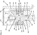
FIG. 3 is a cross-sectional view of the actuation unit ofFIG. 2 disposed within an example implementation of a pressure switch body; and -
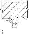
FIG. 4 is an enlarged view of a portion ofFIG. 2 . - Reference will now be made in detail to exemplary aspects of the present disclosure that are illustrated in the accompanying drawings. Wherever possible, the same reference numbers will be used throughout the drawings to refer to the same or like parts.
- The present disclosure is directed to a
pressure switch 150 having a safeguard against over engaging theswitching component 102 with excessive displacement/force. Thepressure switch 150 includes anactuation unit 120 that replaces theactuator 104 andpiston 106 of the pressure switch 100 ofFIG. 1 . Theactuation unit 120 includes amain body 122 extending along a length L from afirst end 124 to asecond end 126. Thefirst end 124 faces thefitting end 114 of thepressure switch housing 112. Thesecond end 126 faces thetrigger 108 of theswitching component 102. - The
actuation unit 120 is movable within the pressure switch housing 112 between an unpressurized position and a pressurized position. In the unpressurized position, thesecond end 126 of theactuation unit 120 does not actuate thetrigger 108 of the switching component 102 (e.g., is spaced from thetrigger 108 or contacts thetrigger 108 without depressing the trigger 108). In the pressurized position, thesecond end 126 of theactuation unit 120 actuates the trigger 108 (e.g., contacts and deflects the trigger 108). - In certain implementations, the
main body 122 of theactuation unit 120 defines ahollow cavity 132 extending along the length L of theactuation unit 120 from thefirst end 124. In certain examples, thehollow cavity 132 extends along a majority of the length L. In certain examples, thefirst end 124 of theactuation unit 120 in conjunction with asurface 134 of thehollow cavity 132 is configured to receive the upward force applied by the fluid entering theswitch body 112 through thefitting end 114. Thehollow cavity 132 lightens theactuation unit body 122, thereby requiring less force to transition theactuation unit 120 between the unpressurized and pressurized positions. - The
actuation unit 120 has asealing region 128 at which aseal arrangement 130 is disposed. Theactuation unit 120 is mounted within theswitch body 112 so that theseal arrangement 130 engages a sealing surface surrounding theactuation unit 120 as theactuation unit 120 slides along the axis A. Theseal arrangement 130 inhibits fluid from thefitting end 114 from reaching theswitching component 102. In the example shown, theseal arrangement 130 includes an O-ring and a washer. In other examples, theseal arrangement 130 may have other configurations (e.g., multiple O-rings). - The
actuation unit 120 includes alimiter 144 that extends radially outwardly from theactuation unit 120 at an intermediate location along the length L of theactuation unit 120. In certain examples, thelimiter 144 includes a radial flange extending outwardly from themain body 122 of theactuation unit 120. In some examples, thelimiter 144 is monolithically formed with themain body 122 of theactuation unit 120. In other examples, thelimiter 144 may be formed of a different material (e.g., a stronger material) from themain body 122. In some examples, thelimiter 144 and/or themain body 122 of theactuation unit 120 is formed from stainless steel (e.g., 300 series stainless steel, 15-5 PH stainless steel, 17-4 PH stainless steel, etc.). In other examples, thelimiter 144 and/or themain body 122 may be formed from an Aluminum alloy. - In certain implementations, a
first insert 140 is disposed within theswitch body 112 and secured to be stationary relative to theswitch body 112. Thefirst insert 140 defines anaperture 141 through which themain body 122 of theactuation unit 120 extends. Thefirst insert 140 cooperates with theswitch body 112 to define the pocket orcavity 118 into which thelimiter 144 extends. The pocket orcavity 118 is sized to enable travel of thelimiter 144 within the pocket orcavity 118 over a distance along the axis A. The distance is sufficiently long to enable movement of thesecond end 126 of theactuation unit 120 from a position in which theswitching component trigger 108 is not actuated to a position in which theswitching component trigger 108 is actuated. In certain examples, the distance is sufficiently long to enable movement of thesecond end 126 from a position in which thesecond end 126 does not contact thetrigger 108 to a position in which thesecond end 126 contacts and actuates thetrigger 108. In other examples, thesecond end 126 always contacts thetrigger 108. In such examples, the distance is sufficiently long to enable sufficient movement of thesecond end 126 to displace thetrigger 108 from a non-actuation position to an actuation position. - In certain implementations, the
limiter 144 engages theinsert body 112 when theactuation unit 120 is disposed in the unpressurized position and thelimiter 144 engages thefirst insert 140 when theactuation unit 120 is disposed in the pressurized position. Engagement between thelimiter 144 and a shoulder of thefirst insert 140 inhibits further movement of thelimiter 144, and hence theactuation unit 120, in the second direction D2. Accordingly, theactuation unit 120 cannot over travel and damage theswitching component 102. - In certain implementations, the
limiter 144 is sized and shaped to fit within the pocket ofcavity 118 while retaining sufficient strength to avoid breaking (e.g., shearing) of thelimiter 144. In certain examples, thelimiter 144 has a thickness T (seeFIG. 4 ) of less than 0.1 inches. In certain examples, thelimiter 144 has a thickness T of between 0.03 inches and 0.1 inches. In certain examples, thelimiter 144 has a thickness T of between 0.038 inches and 0.09 inches. In certain examples, the thickness T is about 0.038 inches to about 0.5 inches. In certain examples, the thickness T is about 0.04 inches to about 0.07 inches. In certain examples, the thickness T is about 0.06 inches to about 0.09 inches. In certain examples, the thickness T is about 0.07 inches to about 0.1 inches. - In certain implementations, a top of the
limiter 144 has a fillet radius R (e.g., seeFIG. 4 ) of less than 0.04 inches. In certain examples, the fillet radius R is between about 0.01 inches to about 0.03 inches. In certain examples, the fillet radius is about 0.01 inches. In certain examples, the fillet radius is about 0.02 inches. In certain examples, the fillet radius is about 0.03 inches. In certain examples, the fillet radius is about 0.015 inches to 0.025 inches. - The
actuation unit 120 has aspring stop region 136 at which aspring arrangement 110 is disposed. In certain examples, thespring stop region 136 defines agroove 138 in which a first end of aspring arrangement 110 may seat. In some implementations, thespring arrangement 110 includes a coil spring. In other implementations, thespring arrangement 110 includes a disc spring. In certain examples, thespring arrangement 110 includes multiple spring members (e.g., disc springs, coil springs, etc.) mounted at thespring stop region 136 to cooperatively produce spring force biasing theactuation unit 120 in the first direction D1. - In certain implementations, a
second insert 142 is disposed within theswitch body 112 and secured to be stationary relative to theswitch body 112. Thesecond insert 142 defines anaperture 143 through which themain body 122 of theactuation unit 120 extends so that thesecond end 126 can reach theswitching component trigger 108. Thesecond insert 142 defines asupport surface 146 configured to receive the opposite end of thespring arrangement 110. - In certain implementations, the
pressure switch 150 is assembled by inserting theactuation unit 120 into achamber 155 of theswitch body 112 through anopen end 152. Theactuation unit 120 is inserted so that the sealingregion 128 extends into a conduit orcavity 125 leading from thechamber 155 to thefitting end 114. Theactuation unit 120 carries theseal arrangement 130 to seal against the conduit orcavity 125 within theswitch body 112. Theseal arrangement 130 seals against fluid from thefitting end 114 reaching thechamber 155. Thelimiter 144 of theactuation unit 120 seats on a shoulder orsupport surface 115 of theswitch body 112 surrounding the conduit orcavity 125. - The
first insert 140 is inserted into thechamber 155 of theswitch body 112 through theopen end 152. Thefirst insert 140 is moved towards thesupport surface 115 so that thesecond end 126 of theactuation unit body 122 passes through theaperture 141 defined through thefirst insert 140. Thefirst insert 140 attaches to theswitch body 112 to be stationary relative to theswitch body 112 during operation of thepressure switch 150. In some examples, thefirst insert 140 is threadably attached to theswitch body 112. In certain examples, fasteners may be added to secure thefirst insert 140 to thesupport surface 115. In other examples, a radial outer wall of thefirst insert 140 may be welded, affixed, or otherwise attached to the interior of theswitch body 112. Thefirst insert 140 cooperates with thesupport surface 115 to trap thelimiter 144 within thepocket 118, thereby restricting movement of theactuation unit 120 relative to theswitch body 112. - In certain implementations, the
body 122 of theactuation unit 120 has a largest cross-dimension CD1 adjacent thelimiter 144 between thelimiter 144 and thesecond end 126. Theaperture 141 of thefirst insert 140 is sized accordingly. In certain examples, a cross-dimension of thebody 122 progressively reduces as thebody 122 extends from thelimiter 144 to thesecond end 126. In certain examples, thebody 122 does not define any undercuts between thelimiter 144 and thesecond end 126. - The
spring arrangement 110 is inserted into thechamber 155 of theswitch body 112 through theopen end 152 and seated at the spring stop region 136 (e.g., in the groove 138). Thesecond insert 142 is inserted into thechamber 155 of theswitch body 112 through theopen end 152 moved towards thefirst insert 140 until thesecond end 126 of theactuation unit 120 extends through theaperture 143. In some implementations, thesecond insert 142 is inserted into theswitch body 112 after thespring arrangement 110. In other implementations, thesecond insert 142 is inserted into theswitch body 112 with the spring arrangement 110 (e.g., thespring arrangement 110 is attached to the second insert 142). Thesecond insert 142 is secured (e.g., threadably mounted) to the interior of theswitch body 112. In the example shown, thesecond insert 142 includes aset screw 147 that seats on thefirst insert 140 to space thesecond insert 142 from thefirst insert 140. - The
switching component 102 is inserted into thechamber 155 of theswitch body 112 through theopen end 152. In certain implementations, theswitching component 102 is mounted to asupport frame 148 that is secured (e.g., threadably mounted) to the interior of theswitch body 102. In the example shown, thesupport frame 148 includes one ormore set screws 149 that seat on thesecond insert 142 to space thesupport frame 148 from thesecond insert 142. In some examples, a fastener may attach thesupport frame 148 to thesecond insert 142. In other examples, thesupport frame 148 and thesecond insert 142 may be combined as single component. Awire 156 extends from theswitching component 102 and through a sealedchannel 158 through theswitch body 112. - A
lid 154 is attached (e.g., bonded, affixed, welded, friction fit, etc.) to theswitch body 112 to close theopen end 152. In certain examples, thelid 154 environmentally seals thechamber 155. -
- 1. A pressure switch arrangement comprising:
- a pressure switch body defining a chamber, the pressure switch body also having a fitting end defining a conduit leading to the chamber;
- a switching component disposed within the chamber of the pressure switch body, the switching component including a trigger;
- an actuation unit disposed within the chamber and being movable relative to the switching component, the actuation unit extending along a length between a first end and a second end, the first end facing the fitting end and the second end facing the trigger, the actuation unit including a limiter disposed at an intermediate position between the first end and the second end, the actuation unit also defining a spring stop region disposed between the limiter and the second end;
- an insert disposed within the chamber of the pressure switch body, the insert defining an aperture through which the actuation unit extends so that at least a portion of the insert is disposed between the limiter and the spring stop region of the actuation unit, the insert cooperating with the pressure switch body to define a pocket into which the limiter radially extends, the limiter being movable within the pocket as the actuation unit moves within the chamber; and
- a spring arrangement engaging the spring stop region of the actuation unit, the spring arrangement biasing the actuation unit away from the trigger of the switching component.
- 2. The pressure switch arrangement of aspect 1, wherein the actuation unit defines a seal region aligned with the conduit.
- 3. The pressure switch arrangement of aspect 1 or aspect 2, wherein the actuation unit does not define any undercuts between the limiter and the second end of the actuation unit.
- 4. The pressure switch arrangement of any of aspects 1-3, wherein the actuation unit is configured to translate within the chamber along a path of travel, and wherein the pocket defines outer boundaries of the path of travel.
- 5. The pressure switch arrangement of any of aspects 1-4, wherein the spring arrangement includes a disc spring.
- 6. The pressure switch arrangement of claim 5, wherein the spring arrangement includes a plurality of disc springs.
- 7. The pressure switch arrangement of any of aspects 1-4, wherein the spring arrangement includes a coil spring.
- 8. The pressure switch arrangement of any of aspects 2-7, further comprising a seal arrangement disposed at the seal region, the seal arrangement including an O-ring.
- 9. The pressure switch arrangement of any of aspects 1-8, wherein the insert is a first insert; and wherein the first insert is threadably mounted to the switch body within the chamber.
- 10. The pressure switch arrangement of aspect 9, further comprising a second insert disposed within the chamber of the switch body, the second insert being configured to support the spring arrangement, the second insert defining an aperture through which the actuation unit extends.
- 11. The pressure switch arrangement of aspect 10, wherein the second insert includes a spacer that spaces the second insert from the first insert.
- 12. The pressure switch arrangement of any of aspects 1-11, wherein the spring stop region of the actuation unit defines a groove configured to receive a first end of the spring arrangement.
- 13. The pressure switch arrangement of any of aspects 1-12, wherein the limiter has a thickness of between 0.038 inches and 0.09 inches.
- 14. The pressure switch arrangement of any of aspects 1-13, wherein the limiter has a fillet radius of between 0.01 inches and 0.03 inches.
- 15. The pressure switch arrangement of any of aspects 1-14, wherein the limiter is formed of stainless steel.
- 16. The pressure switch arrangement of aspect 15, wherein the limiter has a thickness of less than 0.07 inches.
- 17. The pressure switch arrangement of any of aspects 1-14, wherein the limiter is formed of Aluminum alloy.
- 18. The pressure switch arrangement of aspect 17, wherein the limiter has a thickness of greater than 0.05 inches.
- Having described the preferred aspects and implementations of the present disclosure, modifications and equivalents of the disclosed concepts may readily occur to one skilled in the art. However, it is intended that such modifications and equivalents be included within the scope of the claims which are appended hereto.
Claims (15)
- A pressure switch arrangement comprising:a pressure switch body defining a chamber, the pressure switch body also having a fitting end defining a conduit leading to the chamber;a switching component disposed within the chamber of the pressure switch body, the switching component including a trigger;an actuation unit disposed within the chamber and being movable relative to the switching component, the actuation unit extending along a length between a first end and a second end, the first end facing the fitting end and the second end facing the trigger, the actuation unit including a limiter disposed at an intermediate position between the first end and the second end, the actuation unit also defining a spring stop region disposed between the limiter and the second end;an insert disposed within the chamber of the pressure switch body, the insert defining an aperture through which the actuation unit extends so that at least a portion of the insert is disposed between the limiter and the spring stop region of the actuation unit, the insert cooperating with the pressure switch body to define a pocket into which the limiter radially extends, the limiter being movable within the pocket as the actuation unit moves within the chamber; anda spring arrangement engaging the spring stop region of the actuation unit, the spring arrangement biasing the actuation unit away from the trigger of the switching component.
- The pressure switch arrangement of claim 1, wherein the actuation unit defines a seal region aligned with the conduit.
- The pressure switch arrangement of claim 1 or claim 2, wherein the actuation unit does not define any undercuts between the limiter and the second end of the actuation unit.
- The pressure switch arrangement of any of claims 1-3, wherein the actuation unit is configured to translate within the chamber along a path of travel, and wherein the pocket defines outer boundaries of the path of travel.
- The pressure switch arrangement of any of claims 1-4, wherein the spring arrangement includes a disc spring.
- The pressure switch arrangement of claim 5, wherein the spring arrangement includes a plurality of disc springs.
- The pressure switch arrangement of any of claims 1-4, wherein the spring arrangement includes a coil spring.
- The pressure switch arrangement of any of claims 2-7, further comprising a seal arrangement disposed at the seal region, the seal arrangement including an O-ring.
- The pressure switch arrangement of any of claims 1-8, wherein the insert is a first insert; and wherein the first insert is threadably mounted to the switch body within the chamber.
- The pressure switch arrangement of claim 9, further comprising a second insert disposed within the chamber of the switch body, the second insert being configured to support the spring arrangement, the second insert defining an aperture through which the actuation unit extends.
- The pressure switch arrangement of claim 10, wherein the second insert includes a spacer that spaces the second insert from the first insert.
- The pressure switch arrangement of any of claims 1-11, wherein the spring stop region of the actuation unit defines a groove configured to receive a first end of the spring arrangement.
- The pressure switch arrangement of any of claims 1-12, wherein the limiter has a thickness of between 0.038 inches and 0.09 inches.
- The pressure switch arrangement of any of claims 1-13, wherein the limiter has a fillet radius of between 0.01 inches and 0.03 inches.
- The pressure switch arrangement of any of claims 1-14, wherein the limiter is formed of stainless steel.
Applications Claiming Priority (1)
| Application Number | Priority Date | Filing Date | Title |
|---|---|---|---|
| IN202111032959 | 2021-07-22 |
Publications (2)
| Publication Number | Publication Date |
|---|---|
| EP4123678A1 true EP4123678A1 (en) | 2023-01-25 |
| EP4123678B1 EP4123678B1 (en) | 2024-05-15 |
Family
ID=82701925
Family Applications (1)
| Application Number | Title | Priority Date | Filing Date |
|---|---|---|---|
| EP22186429.1A Active EP4123678B1 (en) | 2021-07-22 | 2022-07-22 | Pressure switch with a piston |
Country Status (2)
| Country | Link |
|---|---|
| US (1) | US11915896B2 (en) |
| EP (1) | EP4123678B1 (en) |
Citations (5)
| Publication number | Priority date | Publication date | Assignee | Title |
|---|---|---|---|---|
| US2327054A (en) * | 1942-04-17 | 1943-08-17 | Wilburt W Mays | Fluid actuated circuit closer |
| US3043929A (en) * | 1960-02-25 | 1962-07-10 | George G Guthrie | Pressure actuated switch |
| GB2074253A (en) * | 1980-04-01 | 1981-10-28 | Maier Andreas | Pressure control apparatus |
| FR2618595A1 (en) * | 1987-07-21 | 1989-01-27 | Jaeger | LOW-SIZE HIGH PRESSURE CONTACTOR |
| EP3832281A1 (en) * | 2019-12-06 | 2021-06-09 | Eaton Intelligent Power Limited | Pressure switch diaphragm sensing element suitable for vacuum applications |
Family Cites Families (11)
| Publication number | Priority date | Publication date | Assignee | Title |
|---|---|---|---|---|
| US2759061A (en) | 1952-03-21 | 1956-08-14 | Philip E Edelman | Pressure switch actuator |
| US2800548A (en) | 1953-07-07 | 1957-07-23 | Walter E Stary | Pressure switch |
| US4229629A (en) | 1979-03-01 | 1980-10-21 | Pawlowski Eugene J | Miniature pneumatic switch actuator |
| JPS612221A (en) * | 1984-06-14 | 1986-01-08 | 本田技研工業株式会社 | pressure switch |
| DE3710645A1 (en) | 1987-03-31 | 1988-10-20 | Delaval Turbine Gmbh | PRESSURE SWITCH |
| US4980675A (en) * | 1990-01-09 | 1990-12-25 | Spectrum Associates | Temperature compensatible pressure monitor and sensor construction |
| JPH07220593A (en) | 1994-02-07 | 1995-08-18 | Taihei Syst Kogyo Kk | Pressure switch |
| JPH09282990A (en) | 1996-04-15 | 1997-10-31 | Yuhshin Co Ltd | Pressure switch device |
| US7605336B2 (en) | 2007-08-30 | 2009-10-20 | Honeywell International Inc. | Pressure switch with adjustable differental setting |
| TWI587345B (en) | 2015-12-14 | 2017-06-11 | National Chung-Shan Institute Of Science And Technology Armaments Bureau | A pressure switch structure |
| TWI627651B (en) * | 2018-01-18 | 2018-06-21 | Nat Chung Shan Inst Science & Tech | Ripple type pressure switch |
-
2022
- 2022-07-22 EP EP22186429.1A patent/EP4123678B1/en active Active
- 2022-07-22 US US17/871,570 patent/US11915896B2/en active Active
Patent Citations (5)
| Publication number | Priority date | Publication date | Assignee | Title |
|---|---|---|---|---|
| US2327054A (en) * | 1942-04-17 | 1943-08-17 | Wilburt W Mays | Fluid actuated circuit closer |
| US3043929A (en) * | 1960-02-25 | 1962-07-10 | George G Guthrie | Pressure actuated switch |
| GB2074253A (en) * | 1980-04-01 | 1981-10-28 | Maier Andreas | Pressure control apparatus |
| FR2618595A1 (en) * | 1987-07-21 | 1989-01-27 | Jaeger | LOW-SIZE HIGH PRESSURE CONTACTOR |
| EP3832281A1 (en) * | 2019-12-06 | 2021-06-09 | Eaton Intelligent Power Limited | Pressure switch diaphragm sensing element suitable for vacuum applications |
Also Published As
| Publication number | Publication date |
|---|---|
| US20230026683A1 (en) | 2023-01-26 |
| US11915896B2 (en) | 2024-02-27 |
| EP4123678B1 (en) | 2024-05-15 |
Similar Documents
| Publication | Publication Date | Title |
|---|---|---|
| US20070145318A1 (en) | Solenoid valve for fluid flow | |
| KR940703765A (en) | VACUUM POWER BRAKE | |
| KR100447347B1 (en) | Solenoid for electromagnetic valve | |
| EP3922888B1 (en) | Sprung gate valves movable by an actuator | |
| JP4474668B2 (en) | Switching valve with position detection mechanism | |
| JP6584829B2 (en) | valve | |
| KR101997107B1 (en) | Leak detectable isolation valve for vacuum process | |
| EP3614025B1 (en) | Two-way valve | |
| KR101595750B1 (en) | Actuating device | |
| US20130277190A1 (en) | Storage module for a hydraulic stored-energy spring mechanism | |
| CN111120667A (en) | Electromagnetic valve | |
| US11915896B2 (en) | Pressure switch piston | |
| MXPA02009193A (en) | Venting valve assembly for castings moulds. | |
| US20170030475A1 (en) | Electrically operated valve | |
| US8813787B2 (en) | Single acting directional control valve | |
| JP2013224737A (en) | Valve | |
| EP3633252A1 (en) | Electromagnetic fluid valve | |
| JP2007513295A (en) | Gas safety valve | |
| KR20170056908A (en) | Diaphragm type valve for cryogenic | |
| US9812274B2 (en) | Arrangement for an electrical switch element with a seal configuration | |
| CN212055852U (en) | Electromagnetic valve | |
| EP3832281A1 (en) | Pressure switch diaphragm sensing element suitable for vacuum applications | |
| US6250200B1 (en) | Brake booster | |
| US4238651A (en) | Snap action fluid pressure switch | |
| CN112833195A (en) | A high-end compact solenoid valve with zero leakage |
Legal Events
| Date | Code | Title | Description |
|---|---|---|---|
| PUAI | Public reference made under article 153(3) epc to a published international application that has entered the european phase |
Free format text: ORIGINAL CODE: 0009012 |
|
| STAA | Information on the status of an ep patent application or granted ep patent |
Free format text: STATUS: THE APPLICATION HAS BEEN PUBLISHED |
|
| AK | Designated contracting states |
Kind code of ref document: A1 Designated state(s): AL AT BE BG CH CY CZ DE DK EE ES FI FR GB GR HR HU IE IS IT LI LT LU LV MC MK MT NL NO PL PT RO RS SE SI SK SM TR |
|
| P01 | Opt-out of the competence of the unified patent court (upc) registered |
Effective date: 20230521 |
|
| STAA | Information on the status of an ep patent application or granted ep patent |
Free format text: STATUS: REQUEST FOR EXAMINATION WAS MADE |
|
| 17P | Request for examination filed |
Effective date: 20230720 |
|
| RBV | Designated contracting states (corrected) |
Designated state(s): AL AT BE BG CH CY CZ DE DK EE ES FI FR GB GR HR HU IE IS IT LI LT LU LV MC MK MT NL NO PL PT RO RS SE SI SK SM TR |
|
| GRAP | Despatch of communication of intention to grant a patent |
Free format text: ORIGINAL CODE: EPIDOSNIGR1 |
|
| STAA | Information on the status of an ep patent application or granted ep patent |
Free format text: STATUS: GRANT OF PATENT IS INTENDED |
|
| INTG | Intention to grant announced |
Effective date: 20240223 |
|
| GRAS | Grant fee paid |
Free format text: ORIGINAL CODE: EPIDOSNIGR3 |
|
| GRAA | (expected) grant |
Free format text: ORIGINAL CODE: 0009210 |
|
| STAA | Information on the status of an ep patent application or granted ep patent |
Free format text: STATUS: THE PATENT HAS BEEN GRANTED |
|
| AK | Designated contracting states |
Kind code of ref document: B1 Designated state(s): AL AT BE BG CH CY CZ DE DK EE ES FI FR GB GR HR HU IE IS IT LI LT LU LV MC MK MT NL NO PL PT RO RS SE SI SK SM TR |
|
| REG | Reference to a national code |
Ref country code: CH Ref legal event code: EP |
|
| REG | Reference to a national code |
Ref country code: IE Ref legal event code: FG4D |
|
| REG | Reference to a national code |
Ref country code: DE Ref legal event code: R096 Ref document number: 602022003457 Country of ref document: DE |
|
| REG | Reference to a national code |
Ref country code: LT Ref legal event code: MG9D |
|
| REG | Reference to a national code |
Ref country code: NL Ref legal event code: MP Effective date: 20240515 |
|
| PG25 | Lapsed in a contracting state [announced via postgrant information from national office to epo] |
Ref country code: IS Free format text: LAPSE BECAUSE OF FAILURE TO SUBMIT A TRANSLATION OF THE DESCRIPTION OR TO PAY THE FEE WITHIN THE PRESCRIBED TIME-LIMIT Effective date: 20240915 |
|
| PG25 | Lapsed in a contracting state [announced via postgrant information from national office to epo] |
Ref country code: BG Free format text: LAPSE BECAUSE OF FAILURE TO SUBMIT A TRANSLATION OF THE DESCRIPTION OR TO PAY THE FEE WITHIN THE PRESCRIBED TIME-LIMIT Effective date: 20240515 |
|
| PG25 | Lapsed in a contracting state [announced via postgrant information from national office to epo] |
Ref country code: HR Free format text: LAPSE BECAUSE OF FAILURE TO SUBMIT A TRANSLATION OF THE DESCRIPTION OR TO PAY THE FEE WITHIN THE PRESCRIBED TIME-LIMIT Effective date: 20240515 Ref country code: FI Free format text: LAPSE BECAUSE OF FAILURE TO SUBMIT A TRANSLATION OF THE DESCRIPTION OR TO PAY THE FEE WITHIN THE PRESCRIBED TIME-LIMIT Effective date: 20240515 |
|
| PG25 | Lapsed in a contracting state [announced via postgrant information from national office to epo] |
Ref country code: GR Free format text: LAPSE BECAUSE OF FAILURE TO SUBMIT A TRANSLATION OF THE DESCRIPTION OR TO PAY THE FEE WITHIN THE PRESCRIBED TIME-LIMIT Effective date: 20240816 |
|
| PG25 | Lapsed in a contracting state [announced via postgrant information from national office to epo] |
Ref country code: PT Free format text: LAPSE BECAUSE OF FAILURE TO SUBMIT A TRANSLATION OF THE DESCRIPTION OR TO PAY THE FEE WITHIN THE PRESCRIBED TIME-LIMIT Effective date: 20240916 |
|
| REG | Reference to a national code |
Ref country code: AT Ref legal event code: MK05 Ref document number: 1687609 Country of ref document: AT Kind code of ref document: T Effective date: 20240515 |
|
| PG25 | Lapsed in a contracting state [announced via postgrant information from national office to epo] |
Ref country code: NL Free format text: LAPSE BECAUSE OF FAILURE TO SUBMIT A TRANSLATION OF THE DESCRIPTION OR TO PAY THE FEE WITHIN THE PRESCRIBED TIME-LIMIT Effective date: 20240515 |
|
| PG25 | Lapsed in a contracting state [announced via postgrant information from national office to epo] |
Ref country code: ES Free format text: LAPSE BECAUSE OF FAILURE TO SUBMIT A TRANSLATION OF THE DESCRIPTION OR TO PAY THE FEE WITHIN THE PRESCRIBED TIME-LIMIT Effective date: 20240515 |
|
| PG25 | Lapsed in a contracting state [announced via postgrant information from national office to epo] |
Ref country code: AT Free format text: LAPSE BECAUSE OF FAILURE TO SUBMIT A TRANSLATION OF THE DESCRIPTION OR TO PAY THE FEE WITHIN THE PRESCRIBED TIME-LIMIT Effective date: 20240515 |
|
| PG25 | Lapsed in a contracting state [announced via postgrant information from national office to epo] |
Ref country code: PL Free format text: LAPSE BECAUSE OF FAILURE TO SUBMIT A TRANSLATION OF THE DESCRIPTION OR TO PAY THE FEE WITHIN THE PRESCRIBED TIME-LIMIT Effective date: 20240515 |
|
| PG25 | Lapsed in a contracting state [announced via postgrant information from national office to epo] |
Ref country code: LV Free format text: LAPSE BECAUSE OF FAILURE TO SUBMIT A TRANSLATION OF THE DESCRIPTION OR TO PAY THE FEE WITHIN THE PRESCRIBED TIME-LIMIT Effective date: 20240515 |
|
| PG25 | Lapsed in a contracting state [announced via postgrant information from national office to epo] |
Ref country code: PT Free format text: LAPSE BECAUSE OF FAILURE TO SUBMIT A TRANSLATION OF THE DESCRIPTION OR TO PAY THE FEE WITHIN THE PRESCRIBED TIME-LIMIT Effective date: 20240916 Ref country code: PL Free format text: LAPSE BECAUSE OF FAILURE TO SUBMIT A TRANSLATION OF THE DESCRIPTION OR TO PAY THE FEE WITHIN THE PRESCRIBED TIME-LIMIT Effective date: 20240515 Ref country code: NO Free format text: LAPSE BECAUSE OF FAILURE TO SUBMIT A TRANSLATION OF THE DESCRIPTION OR TO PAY THE FEE WITHIN THE PRESCRIBED TIME-LIMIT Effective date: 20240815 Ref country code: NL Free format text: LAPSE BECAUSE OF FAILURE TO SUBMIT A TRANSLATION OF THE DESCRIPTION OR TO PAY THE FEE WITHIN THE PRESCRIBED TIME-LIMIT Effective date: 20240515 Ref country code: LV Free format text: LAPSE BECAUSE OF FAILURE TO SUBMIT A TRANSLATION OF THE DESCRIPTION OR TO PAY THE FEE WITHIN THE PRESCRIBED TIME-LIMIT Effective date: 20240515 Ref country code: IS Free format text: LAPSE BECAUSE OF FAILURE TO SUBMIT A TRANSLATION OF THE DESCRIPTION OR TO PAY THE FEE WITHIN THE PRESCRIBED TIME-LIMIT Effective date: 20240915 Ref country code: HR Free format text: LAPSE BECAUSE OF FAILURE TO SUBMIT A TRANSLATION OF THE DESCRIPTION OR TO PAY THE FEE WITHIN THE PRESCRIBED TIME-LIMIT Effective date: 20240515 Ref country code: GR Free format text: LAPSE BECAUSE OF FAILURE TO SUBMIT A TRANSLATION OF THE DESCRIPTION OR TO PAY THE FEE WITHIN THE PRESCRIBED TIME-LIMIT Effective date: 20240816 Ref country code: FI Free format text: LAPSE BECAUSE OF FAILURE TO SUBMIT A TRANSLATION OF THE DESCRIPTION OR TO PAY THE FEE WITHIN THE PRESCRIBED TIME-LIMIT Effective date: 20240515 Ref country code: ES Free format text: LAPSE BECAUSE OF FAILURE TO SUBMIT A TRANSLATION OF THE DESCRIPTION OR TO PAY THE FEE WITHIN THE PRESCRIBED TIME-LIMIT Effective date: 20240515 Ref country code: BG Free format text: LAPSE BECAUSE OF FAILURE TO SUBMIT A TRANSLATION OF THE DESCRIPTION OR TO PAY THE FEE WITHIN THE PRESCRIBED TIME-LIMIT Effective date: 20240515 Ref country code: AT Free format text: LAPSE BECAUSE OF FAILURE TO SUBMIT A TRANSLATION OF THE DESCRIPTION OR TO PAY THE FEE WITHIN THE PRESCRIBED TIME-LIMIT Effective date: 20240515 Ref country code: RS Free format text: LAPSE BECAUSE OF FAILURE TO SUBMIT A TRANSLATION OF THE DESCRIPTION OR TO PAY THE FEE WITHIN THE PRESCRIBED TIME-LIMIT Effective date: 20240815 |
|
| PG25 | Lapsed in a contracting state [announced via postgrant information from national office to epo] |
Ref country code: DK Free format text: LAPSE BECAUSE OF FAILURE TO SUBMIT A TRANSLATION OF THE DESCRIPTION OR TO PAY THE FEE WITHIN THE PRESCRIBED TIME-LIMIT Effective date: 20240515 |
|
| PG25 | Lapsed in a contracting state [announced via postgrant information from national office to epo] |
Ref country code: EE Free format text: LAPSE BECAUSE OF FAILURE TO SUBMIT A TRANSLATION OF THE DESCRIPTION OR TO PAY THE FEE WITHIN THE PRESCRIBED TIME-LIMIT Effective date: 20240515 |
|
| PG25 | Lapsed in a contracting state [announced via postgrant information from national office to epo] |
Ref country code: CZ Free format text: LAPSE BECAUSE OF FAILURE TO SUBMIT A TRANSLATION OF THE DESCRIPTION OR TO PAY THE FEE WITHIN THE PRESCRIBED TIME-LIMIT Effective date: 20240515 |
|
| PG25 | Lapsed in a contracting state [announced via postgrant information from national office to epo] |
Ref country code: RO Free format text: LAPSE BECAUSE OF FAILURE TO SUBMIT A TRANSLATION OF THE DESCRIPTION OR TO PAY THE FEE WITHIN THE PRESCRIBED TIME-LIMIT Effective date: 20240515 Ref country code: SK Free format text: LAPSE BECAUSE OF FAILURE TO SUBMIT A TRANSLATION OF THE DESCRIPTION OR TO PAY THE FEE WITHIN THE PRESCRIBED TIME-LIMIT Effective date: 20240515 |
|
| PG25 | Lapsed in a contracting state [announced via postgrant information from national office to epo] |
Ref country code: SM Free format text: LAPSE BECAUSE OF FAILURE TO SUBMIT A TRANSLATION OF THE DESCRIPTION OR TO PAY THE FEE WITHIN THE PRESCRIBED TIME-LIMIT Effective date: 20240515 |
|
| PG25 | Lapsed in a contracting state [announced via postgrant information from national office to epo] |
Ref country code: SM Free format text: LAPSE BECAUSE OF FAILURE TO SUBMIT A TRANSLATION OF THE DESCRIPTION OR TO PAY THE FEE WITHIN THE PRESCRIBED TIME-LIMIT Effective date: 20240515 Ref country code: SK Free format text: LAPSE BECAUSE OF FAILURE TO SUBMIT A TRANSLATION OF THE DESCRIPTION OR TO PAY THE FEE WITHIN THE PRESCRIBED TIME-LIMIT Effective date: 20240515 Ref country code: RO Free format text: LAPSE BECAUSE OF FAILURE TO SUBMIT A TRANSLATION OF THE DESCRIPTION OR TO PAY THE FEE WITHIN THE PRESCRIBED TIME-LIMIT Effective date: 20240515 Ref country code: EE Free format text: LAPSE BECAUSE OF FAILURE TO SUBMIT A TRANSLATION OF THE DESCRIPTION OR TO PAY THE FEE WITHIN THE PRESCRIBED TIME-LIMIT Effective date: 20240515 Ref country code: DK Free format text: LAPSE BECAUSE OF FAILURE TO SUBMIT A TRANSLATION OF THE DESCRIPTION OR TO PAY THE FEE WITHIN THE PRESCRIBED TIME-LIMIT Effective date: 20240515 Ref country code: CZ Free format text: LAPSE BECAUSE OF FAILURE TO SUBMIT A TRANSLATION OF THE DESCRIPTION OR TO PAY THE FEE WITHIN THE PRESCRIBED TIME-LIMIT Effective date: 20240515 |
|
| PG25 | Lapsed in a contracting state [announced via postgrant information from national office to epo] |
Ref country code: MC Free format text: LAPSE BECAUSE OF FAILURE TO SUBMIT A TRANSLATION OF THE DESCRIPTION OR TO PAY THE FEE WITHIN THE PRESCRIBED TIME-LIMIT Effective date: 20240515 |
|
| REG | Reference to a national code |
Ref country code: DE Ref legal event code: R097 Ref document number: 602022003457 Country of ref document: DE |
|
| PG25 | Lapsed in a contracting state [announced via postgrant information from national office to epo] |
Ref country code: LU Free format text: LAPSE BECAUSE OF NON-PAYMENT OF DUE FEES Effective date: 20240722 |
|
| PLBE | No opposition filed within time limit |
Free format text: ORIGINAL CODE: 0009261 |
|
| STAA | Information on the status of an ep patent application or granted ep patent |
Free format text: STATUS: NO OPPOSITION FILED WITHIN TIME LIMIT |
|
| PG25 | Lapsed in a contracting state [announced via postgrant information from national office to epo] |
Ref country code: LU Free format text: LAPSE BECAUSE OF NON-PAYMENT OF DUE FEES Effective date: 20240722 |
|
| 26N | No opposition filed |
Effective date: 20250218 |
|
| PG25 | Lapsed in a contracting state [announced via postgrant information from national office to epo] |
Ref country code: SI Free format text: LAPSE BECAUSE OF FAILURE TO SUBMIT A TRANSLATION OF THE DESCRIPTION OR TO PAY THE FEE WITHIN THE PRESCRIBED TIME-LIMIT Effective date: 20240515 Ref country code: BE Free format text: LAPSE BECAUSE OF NON-PAYMENT OF DUE FEES Effective date: 20240731 |
|
| REG | Reference to a national code |
Ref country code: BE Ref legal event code: MM Effective date: 20240731 |
|
| PGFP | Annual fee paid to national office [announced via postgrant information from national office to epo] |
Ref country code: FR Payment date: 20250620 Year of fee payment: 4 |
|
| PG25 | Lapsed in a contracting state [announced via postgrant information from national office to epo] |
Ref country code: IE Free format text: LAPSE BECAUSE OF NON-PAYMENT OF DUE FEES Effective date: 20240722 |
|
| PG25 | Lapsed in a contracting state [announced via postgrant information from national office to epo] |
Ref country code: SE Free format text: LAPSE BECAUSE OF FAILURE TO SUBMIT A TRANSLATION OF THE DESCRIPTION OR TO PAY THE FEE WITHIN THE PRESCRIBED TIME-LIMIT Effective date: 20240515 |
|
| PGFP | Annual fee paid to national office [announced via postgrant information from national office to epo] |
Ref country code: DE Payment date: 20250620 Year of fee payment: 4 |
|
| PGFP | Annual fee paid to national office [announced via postgrant information from national office to epo] |
Ref country code: IT Payment date: 20250731 Year of fee payment: 4 |
|
| PG25 | Lapsed in a contracting state [announced via postgrant information from national office to epo] |
Ref country code: CY Free format text: LAPSE BECAUSE OF FAILURE TO SUBMIT A TRANSLATION OF THE DESCRIPTION OR TO PAY THE FEE WITHIN THE PRESCRIBED TIME-LIMIT; INVALID AB INITIO Effective date: 20220722 |
|
| REG | Reference to a national code |
Ref country code: CH Ref legal event code: H13 Free format text: ST27 STATUS EVENT CODE: U-0-0-H10-H13 (AS PROVIDED BY THE NATIONAL OFFICE) Effective date: 20260224 |
|
| PG25 | Lapsed in a contracting state [announced via postgrant information from national office to epo] |
Ref country code: HU Free format text: LAPSE BECAUSE OF FAILURE TO SUBMIT A TRANSLATION OF THE DESCRIPTION OR TO PAY THE FEE WITHIN THE PRESCRIBED TIME-LIMIT; INVALID AB INITIO Effective date: 20220722 |
|
| PG25 | Lapsed in a contracting state [announced via postgrant information from national office to epo] |
Ref country code: CH Free format text: LAPSE BECAUSE OF NON-PAYMENT OF DUE FEES Effective date: 20250731 |