EP4123624A1 - Display device - Google Patents
Display device Download PDFInfo
- Publication number
- EP4123624A1 EP4123624A1 EP20768244.4A EP20768244A EP4123624A1 EP 4123624 A1 EP4123624 A1 EP 4123624A1 EP 20768244 A EP20768244 A EP 20768244A EP 4123624 A1 EP4123624 A1 EP 4123624A1
- Authority
- EP
- European Patent Office
- Prior art keywords
- display device
- handheld device
- hole
- frame
- chute
- Prior art date
- Legal status (The legal status is an assumption and is not a legal conclusion. Google has not performed a legal analysis and makes no representation as to the accuracy of the status listed.)
- Pending
Links
Images



Classifications
-
- G—PHYSICS
- G09—EDUCATION; CRYPTOGRAPHY; DISPLAY; ADVERTISING; SEALS
- G09F—DISPLAYING; ADVERTISING; SIGNS; LABELS OR NAME-PLATES; SEALS
- G09F9/00—Indicating arrangements for variable information in which the information is built-up on a support by selection or combination of individual elements
-
- G—PHYSICS
- G06—COMPUTING OR CALCULATING; COUNTING
- G06F—ELECTRIC DIGITAL DATA PROCESSING
- G06F1/00—Details not covered by groups G06F3/00 - G06F13/00 and G06F21/00
- G06F1/16—Constructional details or arrangements
- G06F1/1601—Constructional details related to the housing of computer displays, e.g. of CRT monitors, of flat displays
- G06F1/1607—Arrangements to support accessories mechanically attached to the display housing
-
- G—PHYSICS
- G06—COMPUTING OR CALCULATING; COUNTING
- G06F—ELECTRIC DIGITAL DATA PROCESSING
- G06F1/00—Details not covered by groups G06F3/00 - G06F13/00 and G06F21/00
- G06F1/16—Constructional details or arrangements
- G06F1/1613—Constructional details or arrangements for portable computers
- G06F1/1626—Constructional details or arrangements for portable computers with a single-body enclosure integrating a flat display, e.g. Personal Digital Assistants [PDAs]
-
- G—PHYSICS
- G06—COMPUTING OR CALCULATING; COUNTING
- G06F—ELECTRIC DIGITAL DATA PROCESSING
- G06F1/00—Details not covered by groups G06F3/00 - G06F13/00 and G06F21/00
- G06F1/16—Constructional details or arrangements
- G06F1/1613—Constructional details or arrangements for portable computers
- G06F1/1633—Constructional details or arrangements of portable computers not specific to the type of enclosures covered by groups G06F1/1615 - G06F1/1626
- G06F1/1637—Details related to the display arrangement, including those related to the mounting of the display in the housing
-
- G—PHYSICS
- G06—COMPUTING OR CALCULATING; COUNTING
- G06F—ELECTRIC DIGITAL DATA PROCESSING
- G06F1/00—Details not covered by groups G06F3/00 - G06F13/00 and G06F21/00
- G06F1/16—Constructional details or arrangements
- G06F1/1613—Constructional details or arrangements for portable computers
- G06F1/1633—Constructional details or arrangements of portable computers not specific to the type of enclosures covered by groups G06F1/1615 - G06F1/1626
- G06F1/1656—Details related to functional adaptations of the enclosure, e.g. to provide protection against EMI, shock, water, or to host detachable peripherals like a mouse or removable expansions units like PCMCIA cards, or to provide access to internal components for maintenance or to removable storage supports like CDs or DVDs, or to mechanically mount accessories
-
- G—PHYSICS
- G06—COMPUTING OR CALCULATING; COUNTING
- G06F—ELECTRIC DIGITAL DATA PROCESSING
- G06F1/00—Details not covered by groups G06F3/00 - G06F13/00 and G06F21/00
- G06F1/16—Constructional details or arrangements
- G06F1/1613—Constructional details or arrangements for portable computers
- G06F1/1633—Constructional details or arrangements of portable computers not specific to the type of enclosures covered by groups G06F1/1615 - G06F1/1626
- G06F1/1675—Miscellaneous details related to the relative movement between the different enclosures or enclosure parts
- G06F1/1681—Details related solely to hinges
-
- H—ELECTRICITY
- H04—ELECTRIC COMMUNICATION TECHNIQUE
- H04M—TELEPHONIC COMMUNICATION
- H04M1/00—Substation equipment, e.g. for use by subscribers
- H04M1/02—Constructional features of telephone sets
- H04M1/0202—Portable telephone sets, e.g. cordless phones, mobile phones or bar type handsets
- H04M1/0279—Improving the user comfort or ergonomics
-
- H—ELECTRICITY
- H04—ELECTRIC COMMUNICATION TECHNIQUE
- H04M—TELEPHONIC COMMUNICATION
- H04M1/00—Substation equipment, e.g. for use by subscribers
- H04M1/02—Constructional features of telephone sets
- H04M1/0202—Portable telephone sets, e.g. cordless phones, mobile phones or bar type handsets
- H04M1/0206—Portable telephones comprising a plurality of mechanically joined movable body parts, e.g. hinged housings
- H04M1/0208—Portable telephones comprising a plurality of mechanically joined movable body parts, e.g. hinged housings characterized by the relative motions of the body parts
- H04M1/0214—Foldable telephones, i.e. with body parts pivoting to an open position around an axis parallel to the plane they define in closed position
-
- H—ELECTRICITY
- H04—ELECTRIC COMMUNICATION TECHNIQUE
- H04M—TELEPHONIC COMMUNICATION
- H04M1/00—Substation equipment, e.g. for use by subscribers
- H04M1/02—Constructional features of telephone sets
- H04M1/0202—Portable telephone sets, e.g. cordless phones, mobile phones or bar type handsets
- H04M1/0206—Portable telephones comprising a plurality of mechanically joined movable body parts, e.g. hinged housings
- H04M1/0208—Portable telephones comprising a plurality of mechanically joined movable body parts, e.g. hinged housings characterized by the relative motions of the body parts
- H04M1/0235—Slidable or telescopic telephones, i.e. with a relative translation movement of the body parts; Telephones using a combination of translation and other relative motions of the body parts
-
- H—ELECTRICITY
- H04—ELECTRIC COMMUNICATION TECHNIQUE
- H04M—TELEPHONIC COMMUNICATION
- H04M1/00—Substation equipment, e.g. for use by subscribers
- H04M1/02—Constructional features of telephone sets
- H04M1/04—Supports for telephone transmitters or receivers
Definitions
- the present invention relates to a field of display technology, in particular to a display device.
- a display device can transform the computer's data into various characters, numbers, symbols, or intuitive images for display, and an input tool such as a keyboard can be used to input commands or data into the computer, and system hardware and software are employed to add, delete, and change the display content whenever necessary.
- Display devices are classified into plasma, liquid crystal, light emitting diode, and cathode ray tube types according to display devices used.
- a screen-to-body ratio of a current mobile terminal is becoming larger and larger.
- a larger screen cannot only improve the appearance performance of the mobile terminal, but also improve the display performance.
- large-screen mobile terminals are increasingly favored by users.
- the current large-screen display device can greatly increase a display area of the screen, the larger size also causes problems such as poor portability, difficulty in gripping by the user, difficulty in operation, and so on. Therefore, there is a need to find a novel display device to solve the above problems.
- An object of the present invention is to provide a display device which can solve the problems of the existing large-screen display device, such as poor portability, difficulty in gripping by the user, difficulty in operation, and so on.
- the present invention provides a display device, which includes: a case, including at least one frame; a chute recessed in an outer surface of the frame; and a handheld device slidably inserted into the chute.
- the handheld device includes: a telescopic plate; and a through hole penetrating the telescopic plate.
- the handheld device further includes a substrate attached to an inner sidewall of the through hole.
- the substrate is a cotton layer and/or a nylon layer.
- an inner sidewall of the through hole is provided with an anti-skid stripe.
- the telescopic plate of the handheld device is a bendable structure.
- the bendable structure includes: a first plate; and a second plate hinged to the first plate.
- the display device further includes: a driving device disposed in the case and configured to control the handheld device to insert into the chute or extend out of the chute.
- the driving device includes a linear motor including a putter, and the putter is connected to the telescopic plate of the handheld device.
- the chute is located on a bottom or a side of the frame.
- the present invention relates to a display device.
- a handheld device on the frame of the case of the display device, when using the display device, the customer can extend his finger into the through hole of the handheld device to improve handheld stability and portability;
- a substrate is provided on the inner sidewall of the through hole to improve the comfort of the handheld device, and an anti-skid stripe is provided on the inner sidewall of the through hole to improve the anti-skid performance and stability of the handheld device.
- the components are formed in direct contact, and may also include embodiments in which additional features may be formed interposing the first and second features, such that the first and second features may not be in direct contact.
- a component is described as “installed to” or “connected to” another component, it can be understood that a component is “directly installed” or “directly connected” to another component, or a component is “ installed to” or “connected with” another component through an intermediate component.
- this embodiment provides a display device 100 including a case 1, a chute 2 and a handheld device 3.
- the display device 100 includes a display area 101, and the case 1 is provided around the display area 101.
- the case 1 is constituted by a first frame 11, a second frame 12, a third frame 13 and a fourth frame 14 connected end to end.
- the first frame 11 is disposed opposite to the third frame 13.
- the second frame 12 is disposed opposite to the fourth frame 14.
- the chute 2 is recessed in the outer surface of the frame.
- the chute 2 is recessed in a bottom surface of the third frame 13.
- the handheld device 3 can be slidably inserted into the chute 2.
- the handheld device 3 includes a telescopic plate 31 and a through hole 32.
- the through hole 32 penetrates the telescopic plate 31.
- a shape of the through hole 32 may be elliptical or circular.
- the through hole 32 is mainly configured to facilitate customers to extend their finger into the through hole 32 to better grasp and operate the display device 100, thereby improving the stability and portability of the display device 100.
- the handheld device 3 further includes a substrate 33 attached to the inner sidewall of the through hole 32.
- the substrate 33 includes a nylon layer 331 and a cotton layer 332.
- the nylon layer 331 is attached to the inner sidewall of the through hole 32; the cotton layer 332 is attached to an inner sidewall of the nylon layer 331.
- the substrate 33 is mainly configured to improve the comfort of the handheld device 3.
- the inner sidewall of the through hole 32 is further provided with an anti-skid stripe 34.
- the anti-skid stripe 34 is provided on an inner sidewall of the cotton layer 332.
- the anti-skid stripes 34 are mainly configured to improve the anti-skid performance of the handheld device 3 and prevent finger from slipping out of the through hole 32.
- the display device 100 further includes a driving device 4, which is provided in the case 1.
- the driving device 4 includes a linear motor 41.
- the linear motor 41 includes a putter 411 connected to the telescopic plate 31 of the handheld device 3.
- the driving device 4 is mainly configured to control the handheld device 3 to be inserted into the chute 2 or extend out of the chute 2.
- this embodiment includes most of the technical features of Embodiment 1, and the difference from Embodiment 1 is that: the chute 2 in this embodiment is recessed in a side surface of the third frame 13 instead of being recessed in the bottom surface of the third frame 13 as in Embodiment 1.
- the telescopic plate 31 in this embodiment has a bendable structure.
- the bendable structure includes a first plate 311 and a second plate 312.
- the second plate 312 is hinged to the first plate 311 by a hinge mechanism 313. That is, the second plate 312 can be flipped 90 degrees relative to the first plate 311 through the hinge mechanism 313, so that the finger can extend into the through hole 32 in a plane parallel to the display area 101, improving the user experience and comfort.
- a handheld device 3 By providing a handheld device 3 on the frame of the case 1 of the display device 100, when using the display device 100, the customer can extend his finger into the through hole 32 of the handheld device 3 to improve handheld stability and portability; further, a substrate 33 is provided on the inner sidewall of the through hole 32 to improve the comfort of the handheld device 3, and an anti-skid stripe 34 is provided on the inner sidewall of the through hole 32 to improve the anti-skid performance and stability of the handheld device 3.
- this embodiment includes most of the technical features of Embodiment 1, and the difference from Embodiment 1 is that: the display device 100 described in this embodiment is a foldable display device.
- the display device 100 of this embodiment includes a first panel 5 and a second panel 6.
- the second panel 6 is hinged on the first panel 5.
- the first panel 5 and the second panel 6 constitute a display area 101, and the case 1 is disposed around the display area 101.
- the display device 100 further includes a limit slot 7 and a limit block 8.
- the first panel 5 and the second panel 6 are folded to overlap each other, and the limit block 8 is embedded in the limit slot 7, so as to avoid misalignment and the like when the display device 100 is folded.
- a handheld device 3 By providing a handheld device 3 on the frame of the case 1 of the display device 100, when using the display device 100, the customer can extend his finger into the through hole 32 of the handheld device 3 to improve handheld stability and portability; further, a substrate 33 is provided on the inner sidewall of the through hole 32 to improve the comfort of the handheld device 3, and an anti-skid stripe 34 is provided on the inner sidewall of the through hole 32 to improve the anti-skid performance and stability of the handheld device 3.
Landscapes
- Engineering & Computer Science (AREA)
- Theoretical Computer Science (AREA)
- Computer Hardware Design (AREA)
- General Engineering & Computer Science (AREA)
- Physics & Mathematics (AREA)
- General Physics & Mathematics (AREA)
- Human Computer Interaction (AREA)
- Signal Processing (AREA)
- Devices For Indicating Variable Information By Combining Individual Elements (AREA)
Abstract
Description
- The present application claims priority to
Chinese patent application no. 202010188808.2 submitted to Chinese Patent Office on March 17, 2020 - The present invention relates to a field of display technology, in particular to a display device.
- A display device can transform the computer's data into various characters, numbers, symbols, or intuitive images for display, and an input tool such as a keyboard can be used to input commands or data into the computer, and system hardware and software are employed to add, delete, and change the display content whenever necessary. Display devices are classified into plasma, liquid crystal, light emitting diode, and cathode ray tube types according to display devices used.
- With increase in user demands, a screen-to-body ratio of a current mobile terminal is becoming larger and larger. A larger screen cannot only improve the appearance performance of the mobile terminal, but also improve the display performance. Currently, large-screen mobile terminals are increasingly favored by users.
- Although the current large-screen display device can greatly increase a display area of the screen, the larger size also causes problems such as poor portability, difficulty in gripping by the user, difficulty in operation, and so on. Therefore, there is a need to find a novel display device to solve the above problems.
- An object of the present invention is to provide a display device which can solve the problems of the existing large-screen display device, such as poor portability, difficulty in gripping by the user, difficulty in operation, and so on.
- In order to solve the above problems, the present invention provides a display device, which includes: a case, including at least one frame; a chute recessed in an outer surface of the frame; and a handheld device slidably inserted into the chute.
- Further, the handheld device includes: a telescopic plate; and a through hole penetrating the telescopic plate.
- Further, the handheld device further includes a substrate attached to an inner sidewall of the through hole.
- Further, the substrate is a cotton layer and/or a nylon layer.
- Further, an inner sidewall of the through hole is provided with an anti-skid stripe.
- Further, the telescopic plate of the handheld device is a bendable structure.
- Further, the bendable structure includes: a first plate; and a second plate hinged to the first plate.
- Further, the display device further includes: a driving device disposed in the case and configured to control the handheld device to insert into the chute or extend out of the chute.
- Further, the driving device includes a linear motor including a putter, and the putter is connected to the telescopic plate of the handheld device.
- Further, the chute is located on a bottom or a side of the frame.
- The present invention relates to a display device. On the one hand, by providing a handheld device on the frame of the case of the display device, when using the display device, the customer can extend his finger into the through hole of the handheld device to improve handheld stability and portability; on the other hand, a substrate is provided on the inner sidewall of the through hole to improve the comfort of the handheld device, and an anti-skid stripe is provided on the inner sidewall of the through hole to improve the anti-skid performance and stability of the handheld device.
- In order to more clearly illustrate the embodiments or the technical solutions of the existing art, the drawings illustrating the embodiments or the existing art will be briefly described below. Obviously, the drawings in the following description merely illustrate some embodiments of the present invention. Other drawings may also be obtained by those skilled in the art according to these figures without paying creative work.
-
FIG. 1 is a schematic structural diagram of a display device ofEmbodiment 1. -
FIG. 2 is a bottom view of a display device ofEmbodiment 1. -
FIG. 3 is a partially enlarged view of a structure in the dotted frame ofFIG. 1 . -
FIG. 4 is an enlarged view of a through hole. -
FIG. 5 is a schematic diagram of connection between a driving device and a handheld device. -
FIG. 6 is a schematic structural diagram of a display device ofEmbodiment 2. -
FIG. 7 is a side view of the display device ofEmbodiment 2. -
FIG. 8 is a schematic structural diagram of a display device ofEmbodiment 3. - Elements in the drawings are designated by reference numerals listed below.
- 100, display device; 101, display area;
- 1, case; 2, chute;
- 3, handheld device; 4, driving device;
- 5, first panel; 6, second panel;
- 7, limit slot; 8, limit block;
- 11, first frame; 12, second frame;
- 13, third frame; 14, fourth frame;
- 31, telescopic plate; 32, through hole;
- 33, substrate; 34, anti-skid stripe;
- 331, nylon layer; 332, cotton layer;
- 41, linear motor; 411, putter;
- 311, first plate; 312, second plate;
- 313, hinge mechanism.
- The preferred embodiments of the present invention are described in detail below with reference to the accompanying drawings, in which FIG. Those skilled in the art will more readily understand how to implement the invention. The present invention may, however, be embodied in many different forms and embodiments, and the scope of the invention is not limited to the embodiments described herein.
- The following description of the various embodiments is provided to illustrate the specific embodiments of the invention. The spatially relative directional terms mentioned in the present invention, such as "upper", "lower", "before", "after", "left", "right", "inside", "outside", "side", etc. and the like, may be used herein for ease of description to describe one element or feature's relationship to another element(s) or feature(s) as illustrated in the figures which are merely references.
- In the drawings, the spatially relative terms are intended to encompass different orientations in addition to the orientation as depicted in the figures.. Moreover, the size and thickness of each component shown in the drawings are arbitrarily shown for ease of understanding and description, and the invention does not limit the size and thickness of each component.
- When a component is described as "on" another component, the components are formed in direct contact, and may also include embodiments in which additional features may be formed interposing the first and second features, such that the first and second features may not be in direct contact. When a component is described as "installed to" or "connected to" another component, it can be understood that a component is "directly installed" or "directly connected" to another component, or a component is " installed to" or "connected with" another component through an intermediate component.
- As shown in
FIGs. 1 and 2 , this embodiment provides adisplay device 100 including acase 1, achute 2 and ahandheld device 3. - As shown in
FIG. 1 , thedisplay device 100 includes adisplay area 101, and thecase 1 is provided around thedisplay area 101. Thecase 1 is constituted by afirst frame 11, asecond frame 12, athird frame 13 and afourth frame 14 connected end to end. Thefirst frame 11 is disposed opposite to thethird frame 13. Thesecond frame 12 is disposed opposite to thefourth frame 14. - As shown in
FIGs. 1 and 2 , thechute 2 is recessed in the outer surface of the frame. In this embodiment, thechute 2 is recessed in a bottom surface of thethird frame 13. - As shown in
FIGs. 1 and 2 , thehandheld device 3 can be slidably inserted into thechute 2. - As shown in
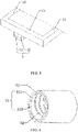
FIG. 3 , thehandheld device 3 includes atelescopic plate 31 and a throughhole 32. The throughhole 32 penetrates thetelescopic plate 31. A shape of the throughhole 32 may be elliptical or circular. The throughhole 32 is mainly configured to facilitate customers to extend their finger into the throughhole 32 to better grasp and operate thedisplay device 100, thereby improving the stability and portability of thedisplay device 100. - As shown in
FIG. 4 , thehandheld device 3 further includes asubstrate 33 attached to the inner sidewall of the throughhole 32. Thesubstrate 33 includes anylon layer 331 and acotton layer 332. Thenylon layer 331 is attached to the inner sidewall of the throughhole 32; thecotton layer 332 is attached to an inner sidewall of thenylon layer 331. Thesubstrate 33 is mainly configured to improve the comfort of thehandheld device 3. - As shown in
FIG. 4 , the inner sidewall of the throughhole 32 is further provided with ananti-skid stripe 34. Specifically, theanti-skid stripe 34 is provided on an inner sidewall of thecotton layer 332. Theanti-skid stripes 34 are mainly configured to improve the anti-skid performance of thehandheld device 3 and prevent finger from slipping out of the throughhole 32. - As shown in
FIG. 5 , thedisplay device 100 further includes adriving device 4, which is provided in thecase 1. The drivingdevice 4 includes alinear motor 41. Thelinear motor 41 includes aputter 411 connected to thetelescopic plate 31 of thehandheld device 3. The drivingdevice 4 is mainly configured to control thehandheld device 3 to be inserted into thechute 2 or extend out of thechute 2. - As shown in
FIGs. 6 and 7 , this embodiment includes most of the technical features ofEmbodiment 1, and the difference fromEmbodiment 1 is that: thechute 2 in this embodiment is recessed in a side surface of thethird frame 13 instead of being recessed in the bottom surface of thethird frame 13 as inEmbodiment 1. - As shown in
FIG. 6 , thetelescopic plate 31 in this embodiment has a bendable structure. The bendable structure includes afirst plate 311 and asecond plate 312. Thesecond plate 312 is hinged to thefirst plate 311 by ahinge mechanism 313. That is, thesecond plate 312 can be flipped 90 degrees relative to thefirst plate 311 through thehinge mechanism 313, so that the finger can extend into the throughhole 32 in a plane parallel to thedisplay area 101, improving the user experience and comfort. - By providing a
handheld device 3 on the frame of thecase 1 of thedisplay device 100, when using thedisplay device 100, the customer can extend his finger into the throughhole 32 of thehandheld device 3 to improve handheld stability and portability; further, asubstrate 33 is provided on the inner sidewall of the throughhole 32 to improve the comfort of thehandheld device 3, and ananti-skid stripe 34 is provided on the inner sidewall of the throughhole 32 to improve the anti-skid performance and stability of thehandheld device 3. - As shown in
FIG. 8 , this embodiment includes most of the technical features ofEmbodiment 1, and the difference fromEmbodiment 1 is that: thedisplay device 100 described in this embodiment is a foldable display device. - As shown in
FIG. 8 , thedisplay device 100 of this embodiment includes afirst panel 5 and asecond panel 6. Thesecond panel 6 is hinged on thefirst panel 5. In an expanded state of thedisplay device 100, thefirst panel 5 and thesecond panel 6 constitute adisplay area 101, and thecase 1 is disposed around thedisplay area 101. - As shown in
FIG. 8 , thedisplay device 100 further includes alimit slot 7 and alimit block 8. In a folded state of thedisplay device 100, thefirst panel 5 and thesecond panel 6 are folded to overlap each other, and thelimit block 8 is embedded in thelimit slot 7, so as to avoid misalignment and the like when thedisplay device 100 is folded. - By providing a
handheld device 3 on the frame of thecase 1 of thedisplay device 100, when using thedisplay device 100, the customer can extend his finger into the throughhole 32 of thehandheld device 3 to improve handheld stability and portability; further, asubstrate 33 is provided on the inner sidewall of the throughhole 32 to improve the comfort of thehandheld device 3, and ananti-skid stripe 34 is provided on the inner sidewall of the throughhole 32 to improve the anti-skid performance and stability of thehandheld device 3. - The display device provided in the embodiments of the present application have been described in detail above. Specific embodiments are used in this document to explain the principles and implementation of the present invention. The descriptions of the above embodiments are only for understanding the method of the present invention and its core ideas, to help understand the technical solution of the present application and its core ideas, and a person of ordinary skill in the art should understand that it can still modify the technical solution described in the foregoing embodiments, or equivalently replace some of the technical features. Such modifications or replacements do not depart the spirit of the corresponding technical solutions beyond the scope of the technical solutions of the embodiments of the present application.
Claims (10)
- A display device, comprising:a case, comprising at least one frame;a chute recessed in an outer surface of the frame; anda handheld device slidably inserted into the chute.
- The display device according to claim 1, wherein the handheld device comprises:a telescopic plate; anda through hole penetrating the telescopic plate.
- The display device according to claim 2, wherein the handheld device further comprises a substrate attached to an inner sidewall of the through hole.
- The display device according to claim 3, wherein the substrate is a cotton layer and/or a nylon layer.
- The display device according to claim 2, wherein an inner sidewall of the through hole is provided with an anti-skid stripe.
- The display device according to claim 1, wherein a telescopic plate of the handheld device is a bendable structure.
- The display device according to claim 6, wherein the bendable structure comprises:a first plate; anda second plate hinged to the first plate.
- The display device according to claim 1, further comprising:
a driving device disposed in the case, and configured to control the handheld device to insert into the chute or extend out of the chute. - The display device according to claim 8, wherein the driving device comprises a linear motor comprising a putter, and the putter is connected to a telescopic plate of the handheld device.
- The display device according to claim 1, wherein the chute is located on a bottom or a side of the frame.
Applications Claiming Priority (2)
| Application Number | Priority Date | Filing Date | Title |
|---|---|---|---|
| CN202010188808.2A CN111261030A (en) | 2020-03-17 | 2020-03-17 | Display device |
| PCT/CN2020/083234 WO2021184437A1 (en) | 2020-03-17 | 2020-04-03 | Display device |
Publications (2)
| Publication Number | Publication Date |
|---|---|
| EP4123624A1 true EP4123624A1 (en) | 2023-01-25 |
| EP4123624A4 EP4123624A4 (en) | 2024-04-24 |
Family
ID=70949725
Family Applications (1)
| Application Number | Title | Priority Date | Filing Date |
|---|---|---|---|
| EP20768244.4A Pending EP4123624A4 (en) | 2020-03-17 | 2020-04-03 | DISPLAY DEVICE |
Country Status (4)
| Country | Link |
|---|---|
| US (1) | US20220317737A1 (en) |
| EP (1) | EP4123624A4 (en) |
| CN (1) | CN111261030A (en) |
| WO (1) | WO2021184437A1 (en) |
Families Citing this family (2)
| Publication number | Priority date | Publication date | Assignee | Title |
|---|---|---|---|---|
| GB2596044A (en) * | 2020-04-10 | 2021-12-22 | Henning Victor | Controlling a portable electronic device with camera |
| US12360570B2 (en) * | 2022-04-20 | 2025-07-15 | Pioneer & Co., Inc. | Underwater controller grip for a device sealed inside a waterproof case |
Family Cites Families (23)
| Publication number | Priority date | Publication date | Assignee | Title |
|---|---|---|---|---|
| US3857397A (en) * | 1972-11-27 | 1974-12-31 | Custom Materials Inc | Electrically conductive wrist strap |
| US4878148A (en) * | 1987-07-22 | 1989-10-31 | Jes, Lp | Crocheted fabric elastic wrist bracelet bearing an interior conductive yarn |
| US5762241A (en) * | 1997-01-29 | 1998-06-09 | Sun Company, Inc. | Watchband |
| US7483262B2 (en) * | 2004-01-15 | 2009-01-27 | Hewlett-Packard Development Company, L.P. | Computer system with multiple-connector apparatus |
| US20080313862A1 (en) * | 2007-06-25 | 2008-12-25 | Brekke-Hutchings Mardella J | Systems and methods for providing a retractable article tether |
| DE202010008994U1 (en) * | 2010-11-10 | 2011-02-17 | Lin, Hsin-Liang | Support structure for a handheld electronic device |
| US8348684B2 (en) * | 2010-12-17 | 2013-01-08 | Research In Motion Limited | Portable electronic device having a concealed jack socket |
| CN202168531U (en) * | 2011-06-09 | 2012-03-21 | 洲码通讯有限公司 | phone case |
| KR101273260B1 (en) * | 2011-09-30 | 2013-06-11 | 백휘광 | Finger backing for A mobile phone |
| WO2014062206A2 (en) * | 2012-10-18 | 2014-04-24 | Smith Stephen Lorance | Mobile device grip |
| JP5370600B1 (en) * | 2013-02-01 | 2013-12-18 | 禪 定井 | Portable electronic terminal holder |
| US9344135B2 (en) * | 2013-07-08 | 2016-05-17 | Jairo Fiorentino | Holding aid to type on a touch sensitive screen for a mobile phone, personal, hand-held, tablet-shaped, wearable devices and methods of use |
| US20160049983A1 (en) * | 2014-08-15 | 2016-02-18 | Alan S Ripka | Apparatus for holding a mobile communication device |
| KR101586254B1 (en) * | 2014-09-15 | 2016-01-22 | 이용훈 | Provided the fitting finger space mobile elctronics case |
| CN204427011U (en) * | 2014-12-24 | 2015-07-01 | 王天帅 | A kind of multi-functional mobile phone case |
| CN204408437U (en) * | 2015-03-10 | 2015-06-17 | 黄明光 | Be suitable for the Mobile phone protecting device of one-handed performance and the finger button for this protective device |
| CN205610694U (en) * | 2016-02-06 | 2016-09-28 | 黄明光 | Device convenient to large -size screen monitors smart mobile phone one -hand operation |
| EP3506609B1 (en) * | 2017-12-21 | 2020-10-07 | Angelo De Roma | Portable multimedia equipment gripping device |
| WO2019180626A1 (en) * | 2018-03-21 | 2019-09-26 | Lazy Design Private Limited | Wearable communication device |
| CN108600432A (en) * | 2018-04-04 | 2018-09-28 | 深圳市华海科技研发有限公司 | Mobile phone back splint |
| CN110385734A (en) * | 2018-04-18 | 2019-10-29 | 徐州市科诺医学仪器设备有限公司 | A kind of novel ring type cutter |
| CN208910227U (en) * | 2018-08-28 | 2019-05-31 | 京东方科技集团股份有限公司 | smart watch |
| US20220026782A1 (en) * | 2020-07-27 | 2022-01-27 | Tim Goldburt | Device for supporting a smartphone or action video camera |
-
2020
- 2020-03-17 CN CN202010188808.2A patent/CN111261030A/en active Pending
- 2020-04-03 EP EP20768244.4A patent/EP4123624A4/en active Pending
- 2020-04-03 WO PCT/CN2020/083234 patent/WO2021184437A1/en not_active Ceased
- 2020-04-03 US US16/761,262 patent/US20220317737A1/en not_active Abandoned
Also Published As
| Publication number | Publication date |
|---|---|
| EP4123624A4 (en) | 2024-04-24 |
| US20220317737A1 (en) | 2022-10-06 |
| CN111261030A (en) | 2020-06-09 |
| WO2021184437A1 (en) | 2021-09-23 |
Similar Documents
| Publication | Publication Date | Title |
|---|---|---|
| US10915194B2 (en) | Touch display panel and touch display device | |
| JP2823182B2 (en) | Mobile phone equipment | |
| US9916028B2 (en) | Touch system and display device for preventing misoperation on edge area | |
| EP3910921B1 (en) | Electronic device, display screen assembly and cover plate | |
| US20050243069A1 (en) | Display-input apparatus for a multi-configuration portable device | |
| US20120144337A1 (en) | Adjustable touch screen keyboard | |
| EP4123624A1 (en) | Display device | |
| JP2009251592A (en) | Organic electroluminescent display device | |
| KR20090018173A (en) | Display control methods, mobile communication terminals and computer readable storage media | |
| CN210225468U (en) | Terminal equipment, center, screen protection cover plate and display screen module | |
| EP4435763A2 (en) | Foldable terminal | |
| EP4560609A1 (en) | Support member, display module, and electronic device | |
| KR20120132955A (en) | Apparatus and method for browsing electronic maps in device with touch screen | |
| CN112002235B (en) | Display device | |
| EP3745247A1 (en) | Display apparatus, electronic device and screen display control method | |
| US12453253B2 (en) | Electronic device including camera module | |
| WO2020187074A1 (en) | Electronic device, display screen assembly, and cover plate | |
| US20050120310A1 (en) | Information processing apparatus and display control method | |
| US20050066477A1 (en) | Swivel structure having direction indication | |
| US11071219B2 (en) | Display apparatus and electronic device | |
| WO2020211634A1 (en) | Mobile terminal and battery cover thereof | |
| WO2020199885A1 (en) | Terminal device | |
| CN107613051A (en) | A kind of display screen and a kind of electronic equipment | |
| CN112987852A (en) | Display device and electronic equipment | |
| CN114326215B (en) | Backlight module and display device |
Legal Events
| Date | Code | Title | Description |
|---|---|---|---|
| STAA | Information on the status of an ep patent application or granted ep patent |
Free format text: STATUS: UNKNOWN |
|
| STAA | Information on the status of an ep patent application or granted ep patent |
Free format text: STATUS: THE INTERNATIONAL PUBLICATION HAS BEEN MADE |
|
| PUAI | Public reference made under article 153(3) epc to a published international application that has entered the european phase |
Free format text: ORIGINAL CODE: 0009012 |
|
| STAA | Information on the status of an ep patent application or granted ep patent |
Free format text: STATUS: REQUEST FOR EXAMINATION WAS MADE |
|
| 17P | Request for examination filed |
Effective date: 20200917 |
|
| AK | Designated contracting states |
Kind code of ref document: A1 Designated state(s): AL AT BE BG CH CY CZ DE DK EE ES FI FR GB GR HR HU IE IS IT LI LT LU LV MC MK MT NL NO PL PT RO RS SE SI SK SM TR |
|
| DAV | Request for validation of the european patent (deleted) | ||
| DAX | Request for extension of the european patent (deleted) | ||
| R17P | Request for examination filed (corrected) |
Effective date: 20200917 |
|
| A4 | Supplementary search report drawn up and despatched |
Effective date: 20240322 |
|
| RIC1 | Information provided on ipc code assigned before grant |
Ipc: H04M 1/02 20060101ALI20240318BHEP Ipc: G06F 1/16 20060101ALI20240318BHEP Ipc: G09F 9/00 20060101AFI20240318BHEP |
|
| STAA | Information on the status of an ep patent application or granted ep patent |
Free format text: STATUS: EXAMINATION IS IN PROGRESS |
|
| 17Q | First examination report despatched |
Effective date: 20260212 |