EP4123604A1 - Identification apparatus, identification method, and training method - Google Patents
Identification apparatus, identification method, and training method Download PDFInfo
- Publication number
- EP4123604A1 EP4123604A1 EP22184108.3A EP22184108A EP4123604A1 EP 4123604 A1 EP4123604 A1 EP 4123604A1 EP 22184108 A EP22184108 A EP 22184108A EP 4123604 A1 EP4123604 A1 EP 4123604A1
- Authority
- EP
- European Patent Office
- Prior art keywords
- feature vector
- format
- identification
- similarity
- identification target
- Prior art date
- Legal status (The legal status is an assumption and is not a legal conclusion. Google has not performed a legal analysis and makes no representation as to the accuracy of the status listed.)
- Granted
Links
Images




Classifications
-
- G—PHYSICS
- G06—COMPUTING OR CALCULATING; COUNTING
- G06V—IMAGE OR VIDEO RECOGNITION OR UNDERSTANDING
- G06V10/00—Arrangements for image or video recognition or understanding
- G06V10/70—Arrangements for image or video recognition or understanding using pattern recognition or machine learning
- G06V10/74—Image or video pattern matching; Proximity measures in feature spaces
- G06V10/761—Proximity, similarity or dissimilarity measures
-
- G—PHYSICS
- G06—COMPUTING OR CALCULATING; COUNTING
- G06V—IMAGE OR VIDEO RECOGNITION OR UNDERSTANDING
- G06V10/00—Arrangements for image or video recognition or understanding
- G06V10/40—Extraction of image or video features
-
- G—PHYSICS
- G06—COMPUTING OR CALCULATING; COUNTING
- G06V—IMAGE OR VIDEO RECOGNITION OR UNDERSTANDING
- G06V10/00—Arrangements for image or video recognition or understanding
- G06V10/70—Arrangements for image or video recognition or understanding using pattern recognition or machine learning
- G06V10/77—Processing image or video features in feature spaces; using data integration or data reduction, e.g. principal component analysis [PCA] or independent component analysis [ICA] or self-organising maps [SOM]; Blind source separation
- G06V10/774—Generating sets of training patterns; Bootstrap methods, e.g. bagging or boosting
-
- G—PHYSICS
- G06—COMPUTING OR CALCULATING; COUNTING
- G06V—IMAGE OR VIDEO RECOGNITION OR UNDERSTANDING
- G06V10/00—Arrangements for image or video recognition or understanding
- G06V10/70—Arrangements for image or video recognition or understanding using pattern recognition or machine learning
- G06V10/82—Arrangements for image or video recognition or understanding using pattern recognition or machine learning using neural networks
-
- G—PHYSICS
- G06—COMPUTING OR CALCULATING; COUNTING
- G06V—IMAGE OR VIDEO RECOGNITION OR UNDERSTANDING
- G06V40/00—Recognition of biometric, human-related or animal-related patterns in image or video data
- G06V40/10—Human or animal bodies, e.g. vehicle occupants or pedestrians; Body parts, e.g. hands
- G06V40/16—Human faces, e.g. facial parts, sketches or expressions
- G06V40/161—Detection; Localisation; Normalisation
-
- G—PHYSICS
- G06—COMPUTING OR CALCULATING; COUNTING
- G06V—IMAGE OR VIDEO RECOGNITION OR UNDERSTANDING
- G06V40/00—Recognition of biometric, human-related or animal-related patterns in image or video data
- G06V40/10—Human or animal bodies, e.g. vehicle occupants or pedestrians; Body parts, e.g. hands
- G06V40/16—Human faces, e.g. facial parts, sketches or expressions
- G06V40/168—Feature extraction; Face representation
-
- G—PHYSICS
- G06—COMPUTING OR CALCULATING; COUNTING
- G06V—IMAGE OR VIDEO RECOGNITION OR UNDERSTANDING
- G06V40/00—Recognition of biometric, human-related or animal-related patterns in image or video data
- G06V40/10—Human or animal bodies, e.g. vehicle occupants or pedestrians; Body parts, e.g. hands
- G06V40/16—Human faces, e.g. facial parts, sketches or expressions
- G06V40/172—Classification, e.g. identification
Definitions
- the present invention relates to an identification apparatus, an identification method, and a training method.
- Japanese Patent No. 4903192 discusses a face detection apparatus.
- the face detection apparatus calculates a face periphery likelihood using a second face detection algorithm.
- the first face detection algorithm is a high-speed face detection algorithm as compared with the second face detection algorithm
- the second face detection algorithm has a high detection rate and a low false detection rate in the face image area as compared with the first face detection algorithm.
- an identification apparatus as specified in claims 1 to 7.
- an identification method as specified in claim 8.
- a training method as specified in claim 9.
- a program as specified in claim 10.
- a model as specified in claim 11.
- a data structure as specified in claim 12.
- an object identification apparatus using face authentication is used as an example of an identification apparatus.
- the exemplary embodiments are not limited to the object identification apparatus using face authentication, and can be applied to recognition of a pet such as a dog or a cat, and recognition of an object such as an automobile or a bicycle.
- the exemplary embodiments may be applied to, other than the object identification apparatus, an image recognition apparatus, a character recognition apparatus, a speech recognition apparatus, and the like, and may be applied to any identification apparatus that performs identification using a feature vector.
- Fig. 1 is a block diagram illustrating a configuration example of an identification apparatus according to a first exemplary embodiment.
- a face authentication apparatus is illustrated as the identification apparatus.
- the face authentication apparatus is capable of identifying who is a human figure seen in a monitoring camera system among preliminarily registered human figures, and can be applied to face authentication in an entrance/exit gate of an entrance/exit management system.
- a program for providing a function of each functional block is stored in a memory such as a read-only memory (ROM).
- the program is implemented by a central processing unit (CPU) loading the program into a random-access memory (RAM) and executing the program.
- a function implemented by hardware for example, a dedicated circuit is only required to be automatically generated from a program for implementing a function of each functional block on a field-programmable gate array (FPGA) circuit using a predetermined compiler.
- the function of each functional block may be implemented as hardware by formation of a gate array circuit similarly to the FPGA circuit.
- the function of each functional block may be implemented by an application-specific integrated circuit (ASIC).
- ASIC application-specific integrated circuit
- the face authentication apparatus includes a detection unit 1, a feature extraction unit 2, and an identification unit 3.
- the detection unit 1 detects a recognition target, that is, a face area, from the input image 11.
- the detection unit 1 is capable of detecting the face area using, for example, Multi-task Cascaded Convolutional Neural Networks for Face Detection based on TensorFlow (MTCNN).
- MTCNN Multi-task Cascaded Convolutional Neural Networks for Face Detection based on TensorFlow
- the feature extraction unit 2 extracts a feature amount from a face image detected by the detection unit 1.
- the feature amount can be expressed by a feature vector 12A.
- the feature vector 12A is designed so as to enable determination of whether a human figure is an identical human figure with high accuracy.
- the feature vector 12A takes a similar value if the human figure is the identical human figure regardless of facial expression, a direction of image-capturing, presence/absence of illumination, and presence/absence of an accessory, and takes a significantly different value if the human figure is a different human figure.
- the identification unit 3 collates the feature vector 12A extracted by the feature extraction unit 2 with feature vectors 12B that are preliminarily registered. In identification processing S13, identified is to which of the preliminarily registered feature vectors 12B the feature vector 12A extracted by the feature extraction unit 2 is the closest. At this time, the identification unit 3 can preliminarily register the feature vectors 12B extracted from images of multitudes of known human figures, and collate the feature vector 12A extracted by the feature extraction unit 2 with each of multitudes of preliminarily registered feature vectors 12B.
- Each of the feature vectors 12A and 12B mentioned herein is an N-dimensional feature vector in a second format (N is an integer that is greater than M) including an M-dimensional feature vector in a first format (M is an integer of 2 or greater).
- the identification unit 3 then identifies a face based on feature vectors in the first format and feature vectors in the second format. At this time, the identification unit 3 calculates a first similarity between feature vectors in the first format. In a case where the first similarity is greater than a predetermined value, the identification unit 3 can calculate a second similarity. In this calculation, a recall ratio of the first similarity can be higher than that of the second similarity, and precision of the second similarity can be higher than that of the first similarity.
- the recall ratio is an identification ratio of the identical object in an input image.
- the recall ratio is a ratio in which a human figure is determined as the identical human figure in a case where the human figure is the identical human figure.
- the precision is a ratio of identification, as the identical human figure, that can be made correctly.
- the precision is a ratio of human figures that are truly identical human figures among human figures that are determined as identical human figures.
- the identification unit 3 eliminates, based on the first similarity, feature vectors of different human figures among feature vectors of multitudes of human figures, and identifies feature vectors of resemblant human figures.
- the identification unit 3 identifies, based on the second similarity, a feature vector of a truly identical human figure among the feature vectors of the resemblant human figures. This eliminates the need of calculation by the identification unit 3 for obtaining a similarity between high-dimensional feature vectors with respect to feature vectors of multitudes of human figures including different human figures, and enables reduction in calculation amount regarding identification while preventing reduction in accuracy of identification.
- Fig. 2 is a block diagram illustrating a detailed configuration example of the identification apparatus according to the first exemplary embodiment.
- an identification apparatus 30 includes an image input unit 31, a detection unit 32, a feature extraction unit 33, an identification unit 34, and a feature holding unit 35.
- the identification unit 34 includes a collation unit 340.
- the collation unit 340 includes a first similarity calculation unit 341 and a second similarity calculation unit 342.
- the detection unit 32, the feature extraction unit 33, and the identification unit 34 can be respectively used as the detection unit 1, the feature extraction unit 2, and the identification unit 3 illustrated in Fig. 1 .
- the image input unit 31 inputs an input image 11 illustrated in Fig. 1 to the detection unit 32.
- the image input unit 31 is, for example, an imaging apparatus such as a camera, or an image recording apparatus.
- the detection unit 32 detects an identification target (face image in this case) from the input image 11, and outputs the identification target to the feature extraction unit 33.
- the feature extraction unit 33 extracts the feature vector 12A from the face image detected by the detection unit 32.
- the feature holding unit 35 holds the feature vectors 12B extracted from the respective images of multitudes of known human figures.
- the identification unit 34 identifies to which of the feature vectors 12B held in the feature holding unit 35 the feature vector 12A extracted by the feature extraction unit 33 is the closest.
- the collation unit 340 collates the feature vectors 12A and 12B with each other, and calculates a similarity between the feature vectors 12A and 12B.
- the first similarity calculation unit 341 calculates the first similarity between the feature vector in the first format in the feature vector 12A and the feature vector in the first format in the feature vector 12B.
- the second similarity calculation unit 342 calculates the second similarity between the feature vector in the second format in the feature vector 12A and the feature vector in the second format in the feature vector 12B. At this time, in a case where the first similarity is greater than a predetermined value, the second similarity calculation unit 342 can calculate the second similarity.
- Fig. 3 is a diagram illustrating a schematic flow of processing of the identification unit 34 illustrated in Fig. 2 .
- Fig. 3 illustrates an example of collating the feature vector 12A and 12B with each other without distinguishing the feature vectors 12A and 12B between the first format and the second format.
- step S21 in Fig. 3 the identification unit 34 in Fig. 2 calculates a similarity between two feature vectors, that is, the feature vector 12A extracted from the input image 11 and one of the preliminarily registered feature vectors 12B, which serve as input.
- the registered feature vectors 12B can include corresponding human figure information 23.
- the similarity takes a large value. If the feature vectors 12A and 12B belong to different human figures, the similarity takes a small value. There is a case where a distance is used instead of the similarity, but meaning thereof is the same. If the feature vectors 12A and 12B are close to each other, the distance takes a value close to zero. If the feature vectors 12A and 12B are not close to each other, the distance (absolute value) takes a large value. In the present specification, the description is given using the similarity, but the distance may be used.
- step S22 the identification unit 34 calculates similarities of all the registered feature vectors 12B to the feature vector 12A, and thereafter calculates a maximum similarity 22, which is a maximum value of similarities.
- step S23 the identification unit 34 compares the maximum similarity 22 with a predetermined value.
- step S24 the identification unit 34 determines that there is a relevant human figure, and identifies the human figure corresponding to the maximum similarity 22 as the human figure seen in the input image 11. In contrast, in a case where the maximum similarity 22 is less than or equal to the predetermined value (NO in step S23), the processing proceeds to step S25. In step S25, the identification unit 34 determines that the feature vector 12A belongs to a human figure that is different from any of registered human figures, and determines that there is no relevant human figure.
- the identification unit 34 calculates the maximum similarity 22 after calculating similarities of all the registered feature vectors 12B, but may update a maximum value of similarities every time a similarity is calculated. Additionally, to reduce the number of collations in step S21, the identification unit 34 may perform clustering of the registered feature vectors 12B.
- the collation processing in step S21 is performed the same number of times as the number of registered feature vectors 12B. For this reason, the number of collations in step S21 is positively correlated to the number of registered feature vectors 12B. As the number of registered feature vectors 12B becomes larger, the number of collations in step S21 becomes larger, and average processing time for collation in step S21 becomes longer. As the number of registered feature vectors 12B becomes larger, a storage capacity of the feature holding unit 35 illustrated in Fig. 2 becomes larger.
- each of the feature vectors 12A and 12B is expressed by the N-dimensional feature vector in the second format including the M-dimensional feature vector in the first format.
- the identification unit 34 then identifies a face based on the feature vector in the first format and the feature vector in the second format.
- Fig. 4 is a diagram illustrating a configuration example of the feature vectors according to the first exemplary embodiment.
- each of the feature vectors 12A and 12B has a data structure in which an M-dimensional feature vector 41 in the first format is included in an N-dimensional feature vector 42 in the second format.
- Each of the feature vectors 12A and 12B has the N-dimensional feature vector 42 in the second format, and can also be handled as the M-dimensional feature vector 41 in the first format when attention is given to the M-dimension, which is part of the feature vector 42. That is, in a case where the two feature vectors 12A and 12B are given to the collation unit 340, the collation unit 340 can calculate the first similarity between the feature vectors 41 in the first format, and also calculate the second similarity between the feature vectors 42 in the second format.
- the feature vector 41 in the first format is set so that a recall ratio with the feature vector 41 in the first format with respect to an identification target (face in this example) is higher than a recall ratio with the feature vector 42 in the second format with respect to the identification target.
- the feature vector 42 in the second format is set so that precision with the feature vector 42 in the second format with respect to the identification target is higher than precision with the feature vector 41 in the first format with respect to the identification target.
- the identification unit 34 can eliminate, based on the collation between the feature vectors 41 in the first format, the feature vectors 42 in the second format each including the feature vector 41 in the first format belonging to a different human figure while leaving the feature vectors 42 in the second format each including the feature vector 41 in the first format belonging to the identical human figure. Then the identification unit 34 can identify the identical human figure based on collation between the feature vectors 42 in the second format obtained by eliminating the feature vectors 42 in the second format each including the feature vector 41 in the first format belonging to a different human figure. At this time, to identify the identical human figure, the identification unit 34 need not perform collation between the feature vectors 42 in the second format each including the feature vector 41 in the first format belonging to a different human figure, and can thereby reduce a calculation amount for collation.
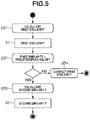
- Fig. 5 is a flowchart describing identification processing according to the first exemplary embodiment.
- step S51 in Fig. 5 the first similarity calculation unit 341 illustrated in Fig. 2 collates the feature vector 41 in the first format in the feature vector 12A and the feature vector 41 in the first format in the feature vector 12B with each other, and calculates a first similarity 51.
- step S52 the identification unit 34 determines whether the first similarity 51 is greater than a predetermined value. In a case where the first similarity 51 is greater than the predetermined value (YES in step S52), the processing proceeds to step S53.
- step S53 the second similarity calculation unit 342 collates the feature vector 42 in the second format in the feature vector 12A and the feature vector 42 in the second format in the feature vector 12B with each other, and calculates a second similarity 52 that serves as a result of collation in step S21 in Fig. 3 .
- the second similarity calculation unit 342 collates the feature vector 42 in the second format including the feature vector 41 in the first format, the first similarity 51 of which is greater than the predetermined value, among the feature vectors 12B held in the feature holding unit 35, with the feature vector 42 in the second format in the feature vector 12A.
- the identification unit 34 when being able to determine that the human figure is not the identical human figure based on the first similarity 51, the identification unit 34 does not calculate the second similarity 52.
- the identification unit 34 can omit calculation of the second similarity 52 to most of the feature vectors 12B held in the feature holding unit 35. For this reason, the identification unit 34 can shorten average time required for calculating a similarity between the feature vectors 12A and 12B in comparison with a case of calculating similarities to all the feature vectors 12B held in the feature holding unit 35.
- the processing in step S52 is processing for suppressing the number of calculations of the second similarity 52 in step S53.
- the second similarity 52 needs to be infallibly calculated in a case where the human figure is the identical human figure.
- the feature vector 12B with which the second similarity 52 is calculated may include the feature vectors 12B belonging to a small number of non-identical human figures.
- the feature vector 41 in the first format is designed to increase a recall ratio basically to 100%
- the feature vector 42 in the second format is designed to increase precision.
- step S54 the identification unit 34 corrects the first similarity 51, and a result of the correction serves as a result of the collation in step S21.
- Similarity correction is correction that enables comparison of a value of the first similarity 51 similarly to the second similarity 52.
- this correction there is a method of correcting the first similarity 51 to be a small constant value that is impossible for the second similarity 52 if the human figure is the identical human figure, and a method of correcting the first similarity 51 to be a value obtained by multiplying the first similarity 51 by a constant so that a small constant value that is impossible for the second similarity 52 if the human figure is the identical human figure is an upper limit value.
- the similarity correction may be performed using any of these methods. However, if only the maximum similarity 22 is used as a result of the collation in step S21 as illustrated in Fig. 3 , it is only required to use the method of correcting the first similarity 51 to be the small constant value that is impossible for the second similarity 52 if the human figure is the identical human figure.
- each of the feature vectors 12A and 12B is expressed as the N-dimensional feature vector in the second format including the M-dimensional feature vector in the first format.
- the identification unit 34 then identifies, based on the feature vector in the first format and the feature vector in the second format, the identification target, and can thereby reduce a calculation amount for collation between feature vectors, and suppress an increase of a storage capacity necessary for registration of a feature vector.
- Fig. 6 is a flowchart describing identification processing according to a second exemplary embodiment.
- the first similarity 51 is calculated in step S51.
- processing time is increased by time required for calculating the first similarity 51.
- an interim result of calculation of the first similarity 51 is used for calculation of the second similarity 52.
- a difference from the processing in Fig. 5 is that an interim result 61 of calculation of the first similarity 51 in step S51 is used for calculation of the second similarity 52 in step S53.
- a similarity between feature vectors for example, a cosine similarity can be used.
- each of the feature vectors F x and F y can be expressed by an N-dimensional vector including an M-dimensional vector as indicated by the following Expressions (1) and (2).
- F x x 1 , x 2 , ... , x M , x M + 1 , ... , x N
- F y y 1 , y 2 , ... , y M , y M + 1 , ... , y N
- the first similarity 51 is, if expressed by a cosine similarity SA1 between M-dimensional vectors, obtained by the following Expression (3).
- the second similarity 52 is, if expressed by a cosine similarity SA2 between N-dimensional vectors, obtained by the following Expression (4).
- ⁇ , ⁇ , ⁇ , ⁇ , ⁇ , and ⁇ are defined as expressed by the following Expressions (5) and (6).
- the cosine similarity SA2 between the N-dimensional vectors is obtained by the following Expression (8) using ⁇ , ⁇ , ⁇ , ⁇ , ⁇ , and ⁇ .
- SA 2 ⁇ ⁇ ⁇ ⁇ + ⁇ ⁇ ⁇ + ⁇
- ⁇ , ⁇ , and ⁇ are also used in calculation of the first similarity 51 in step S51 and calculation of the second similarity 52 in step S53.
- the second similarity calculation unit 342 uses the values of ⁇ , ⁇ , and ⁇ calculated by the first similarity calculation unit 341 for calculation of the second similarity 52 as the interim result 61.
- the collation in step S21 in Fig. 3 merely increases a calculation amount for performing multiplication, division, and calculation of a square root one time each as compared with a case of performing calculation of the first similarity 51 and calculation of the second similarity 52.
- the identification apparatus 30 preliminarily calculates 1/ ⁇ , 1/ ⁇ , 1/ ⁇ ( ⁇ + ⁇ ), and 1/ ⁇ ( ⁇ + ⁇ ) at the time of feature extraction, and adds a result of the calculation to the feature vector.
- the cosine similarity SA1 between the M-dimensional vectors is obtained by the following Expression (9).
- the cosine similarity SA2 between the N-dimensional vectors is obtained by the following Expression (10). Consequently, a calculation amount for collation in step S21 is merely increased by an amount for calculating multiplication two times.
- the second similarity 52 is not calculated in most cases of collation in step S21 in Fig. 3 .
- processing time required for calculating the first similarity 51 itself is increased.
- the second exemplary embodiment even in the case where multitudes of similar feature vectors 12B are registered, it is possible to suppress an increase in time required for calculating the similarity.
- Each of the feature vectors 12A and 12B exhibits a higher recall ratio in the M-dimensional first format, and higher identification performance in the N-dimensional second format. Designing each of the feature vectors 12A and 12B in this manner can reduce a calculation amount for identifying the identical human figure as compared with a case of designing the feature vectors so as to increase only the identification performance in the N-dimensional second format.
- any feature extraction unit that can extract the feature vector 12A exhibiting a higher recall ratio in the M-dimensional first format and higher identification performance in the N-dimensional second format from the face image may be used.
- the feature extraction unit 33 may be generated using a deep neural network.
- a deep neural network There are various kinds of methods as a method of training the deep neural network for identifying an object, a method of Siamese Network [Bromley, 1993] is used as an example in a third exemplary embodiment.
- Fig. 7 is a block diagram illustrating a configuration example of a training apparatus according to the third exemplary embodiment.
- a training apparatus 7 includes a deep neural network (DNN) unit 72 and a weight updating unit 74.
- the DNN unit 72 includes DNNs 721 and 722.
- the DNNs 721 and 722 each has an identical configuration.
- the weight updating unit 74 includes a first loss function 741 and a second loss function 742.
- An image pair 71 which is a pair of images 711 and 712, is input to the DNN unit 72, a feature vector pair 73, which is a pair of N-dimensional feature vectors 731 and 732, is output from the DNN unit 72. At this time, the image pair 71 corresponds to the feature vector pair 73.
- a label T which indicates whether the human figure is the identical human figure and is not illustrated, is additionally provided to the image pair 71. In a case where the human figure is the identical human figure, the label T takes a value of "1". In a case where the human figure is not the identical human figure, the label T takes a value of "0".
- the image pair 71 to which the label T is additionally provided can be used as training data that trains each of the DNNs 721 and 722.
- the training apparatus 7 acquires training data to train each of the DNNs 721 and 722.
- the image 711 is input to the DNN 721 and the image 712 is input to the DNN 722.
- the DNNs 721 and 722 extract the N-dimensional feature vectors 731 and 732 from the images 711 and 712, respectively.
- the N-dimensional feature vectors 731 and 732 include M-dimensional feature vectors 7311 and 7321, respectively.
- the DNN 721 is trained to extract the M-dimensional feature vector 7311 as the feature vector 41 in the first format, and extract the N-dimensional feature vector 731 as the feature vector 42 in the second format.
- the DNN 722 is trained to extract the M-dimensional feature vector 7321 as the feature vector 41 in the first format, and extract the N-dimensional feature vector 732 as the feature vector 42 in the second format.
- the first loss function 741 is designed to increase identification performance of the feature vector 41 in the first format with the M-dimensional feature vectors 7311 and 7321 serving as input.
- the second loss function 742 is designed to increase identification performance of the feature vector 42 in the second format with the N-dimensional feature vectors 731 and 732 serving as input.
- the weight updating unit 74 updates a parameter (weight) of the DNN unit 72 based on the first loss function 741 and the second loss function 742.
- the first loss function 741 is a contrastive loss function for the feature vectors 7311 and 7321.
- a margin is set to be low to increase a recall ratio.
- the margin is called a hyper parameter, and is adjusted based on an experience, or adjusted while training proceeds.
- D represents a distance between the feature vectors 7311 and 7321. For example, it is only required to use the Euclidean distance as D.
- the contrastive loss function may be used similarly to the first loss function 741, or another function may be used.
- the margin may be different from a value of the first loss function 741.
- the Euclidean distance may be used as D, but another distance index such as the Manhattan distance may be used, or a similarity may be converted to a distance and then used.
- the weight updating unit 74 determines the first loss function 741 and the second loss function 742, and then combines these functions into a loss function L total .
- the loss function L total can be obtained by the following Expression (14).
- L total sL 1 + 1 ⁇ s L 2
- s is a parameter of 0 ⁇ s ⁇ 1, and is not necessarily a fixed value throughout a period of training.
- s may be a constant value throughout the entire period of the training, or may be 1 or a value close to 1 at the beginning of the training and thereafter be gradually decreased to a predetermined value.
- the weight updating unit 74 uses the loss function Ltotai to update the weight assigned to the DNN unit 72. At this time, since the DNNs 721 and 722 constitute the Siamese Network, weights assigned to the DNNs 721 and 722 are simultaneously updated. The trained DNNs 721 and 722 can be used as the feature extraction unit 33 without being changed.
- the training apparatus 7 uses the first loss function 741 and the second loss function 742 to train the DNNs 721 and 722.
- the feature extraction unit 33 that extracts the feature vector 12A exhibiting a high recall ratio in the M-dimensional first format and high identification performance in the N-dimensional second format can be configured using the DNNs 721 and 722.
- Fig. 8 is a block diagram illustrating a configuration example of an identification apparatus according to the fourth exemplary embodiment.
- an identification apparatus 8 includes a DNN 82, a feature amount storage unit 85, and a similarity calculation unit 86.
- the similarity calculation unit 86 includes a first similarity calculation unit 861 and a second similarity calculation unit 862.
- the DNN 82 extracts an N-dimensional feature vector 832 from an image 81.
- the N-dimensional feature vector 832 includes an M-dimensional feature vector 831.
- the DNN 82 extracts the M-dimensional feature vector 831 as the feature vector 41 in the first format, and extracts the N-dimensional feature vector 832 as the feature vector 42 in the second format.
- the feature amount storage unit 85 stores N-dimensional feature vectors 852 extracted from respective images of multitudes of known human figures. At this time, the N-dimensional feature vector 852 includes an M-dimensional feature vector 851. At this time, the M-dimensional feature vector 851 is extracted as the feature vector 41 in the first format, and the N-dimensional feature vector 852 is extracted as the feature vector 42 in the second format.
- the first similarity calculation unit 861 collates the M-dimensional feature vector 831 output from the DNN 82 and the M-dimensional feature vector 841 read out from the feature amount storage unit 85 with each other, and calculates a first similarity between the feature vectors 831 and 841.
- the second similarity calculation unit 862 collates the N-dimensional feature vector 832 output from the DNN 82 and the N-dimensional feature vector 842 read out from the feature amount storage unit 85 with each other, and calculates a second similarity between the feature vectors 832 and 842.
- the second similarity calculation unit 862 collates, among the N-dimensional feature vectors 842 read out from the feature amount storage unit 85, an N-dimensional feature vector 842 including an M-dimensional feature vector 841 whose first similarity is greater than a predetermined value with the N-dimensional feature vector 832. For this reason, the second similarity calculation unit 862 omits collation of the N-dimensional feature vector 842 including the M-dimensional feature vector 841 whose first similarity is less than or equal to the predetermined value with the N-dimensional feature vector 832.
- the first similarity to the M-dimensional feature vector 841 is less than or equal to the predetermined value in most cases. For this reason, also in a case where multitudes of N-dimensional feature vectors 852 are stored in the feature amount storage unit 85, the second similarity calculation unit 862 can shorten time for collation with the N-dimensional feature vector 832.
- Fig. 9 is a diagram illustrating an example of a model used for feature extraction according to a fifth exemplary embodiment.
- a neural network is illustrated as an example of the model used for feature extraction.
- the model illustrated in Fig. 9 can be used as the DNN 82 illustrated in Fig. 8 .
- the neural network includes an input layer LI, an intermediate layer LH, and an output layer LO.
- the input layer LI includes a node NI
- the intermediate layer LH includes a node NH
- the output layer LO includes a node NO.
- the node NI is coupled to the node NH via an edge EI
- nodes NH are coupled to each other via an edge EH
- the node NH is coupled to the node NO via an edge EO.
- Input data DI including an identification target is input to the input layer LI.
- the output layer LO outputs the N-dimensional feature vector 42 in the second format including the M-dimensional feature vector 41 in the first format with respect to the identification target input to the input layer LI.
- the intermediate layer LH is trained to output, via the output layer LO, the N-dimensional feature vector 42 in the second format including the M-dimensional feature vector 41 in the first format with respect to the identification target input to the input layer LI, with output from the input layer LI serving as input.
- a trained model can be generated by training the neural network using the training apparatus 7 illustrated in Fig. 7 .
- the input data DI including the identification target is input to the input layer LI.
- the neural network then performs calculation on the output from the input layer LI in the intermediate layer LH, and outputs, from the output layer LO, the N-dimensional feature vector 42 in the second format including the M-dimensional feature vector 41 in the first format with respect to the identification target.
- a weight of each edge EI is assigned to the data input to each node NI of the input layer LI, thereafter the weighted data is input to each node NH of the intermediate layer LH, and the input to each node NH is added to serve as a value of each node NH.
- the value of each node NH of the intermediate layer LH is non-linearly transformed by an activation function (for example, a Sigmoid function).
- Weights of the edges EH and EO are assigned to the transformed value, thereafter the weighted value is input to each node NO of the output layer LO, and the input to each node NO is added to serve as a value of each node NO.
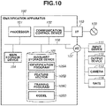
- Fig. 10 is a block diagram illustrating a hardware configuration example of an identification apparatus according to a sixth exemplary embodiment.
- An identification apparatus 100 can provide functions implemented by software among the functional blocks illustrated in Figs. 1 , 2 , and 8 .
- the identification apparatus 100 includes a processor 101, a communication control device 102, a communication interface 103, a main storage device 104, an auxiliary storage device 105, and an input/output interface 107.
- the processor 101, the communication control device 102, the communication interface 103, the main storage device 104, the auxiliary storage device 105, and the input/output interface 107 are connected to each other via an internal bus 106.
- the main storage device 104 and the auxiliary storage device 105 can be accessed from the processor 101.
- an input device 111, an output device 112, a camera 113, and a gate 114 are arranged outside the identification apparatus 100.
- the input device 111, the output device 112, the camera 113, and the gate 114 are connected to the internal bus 106 via the input/output interface 107.
- Each of the input device 111 and the output device 112 can be used as a human interface.
- the input device 111 is, for example, a keyboard, a mouse, or a touch panel, a card reader, and a speech input device.
- the output device 112 is, for example, a screen display device (a liquid crystal monitor, an organic electro luminescence (EL) display, a graphics card, or the like), a speech output device (speaker or the like), or a print device.
- the camera 113 for example, captures an image of the face of a human figure and the like.
- the gate 114 opens/closes based on a result of identification of a human figure by the identification apparatus 100.
- the gate 114 is, for example, an entrance/exit gate of an entrance/exit management system.
- the processor 101 is hardware in charge of controlling operations of the whole of the identification apparatus 100.
- the processor 101 may be a CPU or a graphics processing unit (GPU).
- the processor 101 may be a single-core processor, or a multicore processor.
- the processor 101 may include a hardware circuit (for example, an FPGA circuit or an ASIC) such as an accelerator that performs part of processing.
- the processor 101 may operate as a neural network.
- the main storage device 104 can be constituted by, for example, a semiconductor memory such as a static random access memory (SRAM) or a dynamic random access memory (DRAM).
- a program being executed by the processor 101 can be stored in the main storage device 104, and a work area that is used by the processor 101 to execute the program can be arranged in the main storage device 104.
- the auxiliary storage device 105 is a storage device provided with a large-storage capacity, and is, for example, a hard disk device or a solid state drive (SSD).
- the auxiliary storage device 105 can hold data used for execution of execution files of various types of programs and execution of the programs.
- the auxiliary storage device 105 can store an identification program 105A, a feature vector 105B, a training program 105C, and a model 105D.
- the identification program 105A, the training program 105C, and the model 105D may be software that can be installed in the identification apparatus 100, or may be incorporated as firmware in the identification apparatus 100.
- the feature vector 105B is the N-dimensional feature vector 42 in the second format including the M-dimensional feature vector 41 in the first format extracted from images of multitudes of known human figures.
- the communication control device 102 is hardware provided with a function of controlling communication with the outside.
- the communication control device 102 is connected to a network 109 via the communication interface 103.
- the network 109 may be the Internet, a wide area network (WAN), or a local area network (LAN) of Wireless Fidelity (Wi-Fi) or Ethernet ® .
- the Internet, the WAN, and the LAN may coexist in the network 109.
- the input/output interface 107 converts data input from the input device 111 or the camera 113 into data in a data format that can be processed by the processor 101. In addition, the input/output interface 107 converts data output from the processor 101 into data in a data format that can be processed by each of the output device 112 and the gate 114.
- the processor 101 loads the identification program 105A and the feature vector 105B that are stored in the auxiliary storage device 105 into the main storage device 104, executes the identification program 105A and the feature vector 105B, and can thereby implement the processing illustrated in Fig. 3 , 5 , or 6 .
- the identification program 105A extracts a feature vector from a face image captured by the camera 113.
- the identification program 105A collates the feature vector extracted from the face image captured by the camera 113 with the feature vector 105B read out from the auxiliary storage device 105, and can thereby implement face authentication.
- the identification program 105A can call the model 105D and receive the feature vector extracted from the face image captured by the camera 113 from the model 105D.
- the processor 101 can load the training program 105C stored in the auxiliary storage device 105 into the main storage device 104 and execute the training program 105C.
- the training program 105C trains the model 105D to extract the N-dimensional feature vector 42 in the second format including the M-dimensional feature vector 41 in the first format illustrated in Fig. 4 from the face image captured by the camera 113.
- the training program 105C can implement functions of the training apparatus 7 illustrated in Fig. 7 .
- the execution of the program for implementing the processing in Fig. 3 , 5 , or 6 may be shared by a plurality of processors or a computer.
- the processor 101 may instruct a cloud computer or the like via the network 109 to execute all or part of the program for implementing the processing in Fig. 3 , 5 , or 6 , and receive a result of the execution.
- a program that implements one or more functions of the above-mentioned exemplary embodiments may be supplied to a system or an apparatus via a network or a storage medium.
- the one or more functions of the above-mentioned exemplary embodiments can be implemented by one or more processors of a computer of the system or the apparatus reading out and executing the program.
- the one or more functions of the above-mentioned exemplary embodiments can also be implemented by a circuit (for example, an FPGA circuit or an ASIC) that implements one or more functions. While the exemplary embodiments of the present invention have been described, the present invention is not limited to these exemplary embodiments and can be modified and changed in various manners without departing from the scope of the present invention.
- Embodiment(s) of the present invention can also be realized by a computer of a system or apparatus that reads out and executes computer executable instructions (e.g., one or more programs) recorded on a storage medium (which may also be referred to more fully as a 'non-transitory computer-readable storage medium') to perform the functions of one or more of the above-described embodiment(s) and/or that includes one or more circuits (e.g., application specific integrated circuit (ASIC)) for performing the functions of one or more of the above-described embodiment(s), and by a method performed by the computer of the system or apparatus by, for example, reading out and executing the computer executable instructions from the storage medium to perform the functions of one or more of the above-described embodiment(s) and/or controlling the one or more circuits to perform the functions of one or more of the above-described embodiment(s).
- computer executable instructions e.g., one or more programs
- a storage medium which may also be referred to more fully as
- the computer may comprise one or more processors (e.g., central processing unit (CPU), micro processing unit (MPU)) and may include a network of separate computers or separate processors to read out and execute the computer executable instructions.
- the computer executable instructions may be provided to the computer, for example, from a network or the storage medium.
- the storage medium may include, for example, one or more of a hard disk, a random-access memory (RAM), a read only memory (ROM), a storage of distributed computing systems, an optical disk (such as a compact disc (CD), digital versatile disc (DVD), or Blu-ray Disc (BD) TM ), a flash memory device, a memory card, and the like.
- An identification apparatus includes an extraction unit configured to extract an N-dimensional feature vector (N is an integer that is greater than M) in a second format including an M-dimensional feature vector (M is an integer of 2 or greater) in a first format from input data, and an identification unit configured to identify an identification target in the input data based on the feature vector in the first format and the feature vector in the second format.
- N is an integer that is greater than M
- M is an integer of 2 or greater
Landscapes
- Engineering & Computer Science (AREA)
- Theoretical Computer Science (AREA)
- Evolutionary Computation (AREA)
- Computer Vision & Pattern Recognition (AREA)
- Physics & Mathematics (AREA)
- General Physics & Mathematics (AREA)
- Multimedia (AREA)
- Computing Systems (AREA)
- Databases & Information Systems (AREA)
- Health & Medical Sciences (AREA)
- General Health & Medical Sciences (AREA)
- Medical Informatics (AREA)
- Software Systems (AREA)
- Artificial Intelligence (AREA)
- Image Analysis (AREA)
Abstract
Description
- The present invention relates to an identification apparatus, an identification method, and a training method.
-
Japanese Patent No. 4903192 - According to a first aspect of the present invention, there is provided an identification apparatus as specified in claims 1 to 7. According to a second aspect of the present invention, there is provided an identification method as specified in
claim 8. According to a third aspect of the present invention, there is provided a training method as specified in claim 9. According to a fourth aspect of the present invention, there is provided a program as specified inclaim 10. According to a fifth aspect of the present invention, there is provided a model as specified inclaim 11. According to a sixth aspect of the present invention, there is provided a data structure as specified in claim 12. - Further features of the present invention will become apparent from the following description of exemplary embodiments with reference to the attached drawings.
-
-
Fig. 1 is a block diagram illustrating a configuration example of an identification apparatus according to a first exemplary embodiment. -
Fig. 2 is a block diagram illustrating a detailed configuration example of the identification apparatus according to the first exemplary embodiment. -
Fig. 3 is a diagram illustrating a schematic flow of processing of an identification unit illustrated inFig. 2 . -
Fig. 4 is a diagram illustrating a configuration example of a feature vector according to the first exemplary embodiment. -
Fig. 5 is a flowchart describing identification processing according to the first exemplary embodiment. -
FIG. 6 is a flowchart describing identification processing according to a second exemplary embodiment. -
Fig. 7 is a block diagram illustrating a configuration example of a training apparatus according to a third exemplary embodiment. -
Fig. 8 is a block diagram illustrating a configuration example of an identification apparatus according to a fourth exemplary embodiment. -
Fig. 9 is a diagram illustrating an example of a model used for feature extraction according to a fifth exemplary embodiment. -
Fig. 10 is a block diagram illustrating a hardware configuration example of an identification apparatus according to a sixth exemplary embodiment. - Exemplary embodiments of the present invention will be described in detail below with reference to the accompanying drawings. The following exemplary embodiments do not limit the present invention, and all combinations of features described in the exemplary embodiments are not necessarily essential to a means for solving the issues of the present invention. A configuration of the exemplary embodiments can be corrected or changed as appropriate depending on a specification of an apparatus to which the present invention is applied and various kinds of conditions (condition of use, usage environment, and the like). The technical scope of the present invention is defined by the claimed invention, and is not limited by the following individual exemplary embodiments.
- In the following description, an object identification apparatus using face authentication is used as an example of an identification apparatus. However, the exemplary embodiments are not limited to the object identification apparatus using face authentication, and can be applied to recognition of a pet such as a dog or a cat, and recognition of an object such as an automobile or a bicycle. The exemplary embodiments may be applied to, other than the object identification apparatus, an image recognition apparatus, a character recognition apparatus, a speech recognition apparatus, and the like, and may be applied to any identification apparatus that performs identification using a feature vector.
-
Fig. 1 is a block diagram illustrating a configuration example of an identification apparatus according to a first exemplary embodiment. In the example inFig. 1 , a face authentication apparatus is illustrated as the identification apparatus. The face authentication apparatus is capable of identifying who is a human figure seen in a monitoring camera system among preliminarily registered human figures, and can be applied to face authentication in an entrance/exit gate of an entrance/exit management system. - As for a function implemented by software among functional blocks illustrated in
Fig. 1 , a program for providing a function of each functional block is stored in a memory such as a read-only memory (ROM). The program is implemented by a central processing unit (CPU) loading the program into a random-access memory (RAM) and executing the program. As for a function implemented by hardware, for example, a dedicated circuit is only required to be automatically generated from a program for implementing a function of each functional block on a field-programmable gate array (FPGA) circuit using a predetermined compiler. Alternatively, the function of each functional block may be implemented as hardware by formation of a gate array circuit similarly to the FPGA circuit. Still alternatively, the function of each functional block may be implemented by an application-specific integrated circuit (ASIC). The configuration of the functional block illustrated inFig. 1 is merely an example, and a plurality of functional blocks may constitute one functional block, or any of functional blocks may be divided into a plurality of functional blocks. - In
Fig. 1 , the face authentication apparatus includes a detection unit 1, afeature extraction unit 2, and anidentification unit 3. - The detection unit 1 detects a recognition target, that is, a face area, from the
input image 11. The detection unit 1 is capable of detecting the face area using, for example, Multi-task Cascaded Convolutional Neural Networks for Face Detection based on TensorFlow (MTCNN).. - The
feature extraction unit 2 extracts a feature amount from a face image detected by the detection unit 1. The feature amount can be expressed by afeature vector 12A. In face authentication processing, thefeature vector 12A is designed so as to enable determination of whether a human figure is an identical human figure with high accuracy. In a case of face authentication, thefeature vector 12A takes a similar value if the human figure is the identical human figure regardless of facial expression, a direction of image-capturing, presence/absence of illumination, and presence/absence of an accessory, and takes a significantly different value if the human figure is a different human figure. - The
identification unit 3 collates thefeature vector 12A extracted by thefeature extraction unit 2 withfeature vectors 12B that are preliminarily registered. In identification processing S13, identified is to which of the preliminarily registeredfeature vectors 12B thefeature vector 12A extracted by thefeature extraction unit 2 is the closest. At this time, theidentification unit 3 can preliminarily register thefeature vectors 12B extracted from images of multitudes of known human figures, and collate thefeature vector 12A extracted by thefeature extraction unit 2 with each of multitudes of preliminarily registeredfeature vectors 12B. - Each of the
feature vectors identification unit 3 then identifies a face based on feature vectors in the first format and feature vectors in the second format. At this time, theidentification unit 3 calculates a first similarity between feature vectors in the first format. In a case where the first similarity is greater than a predetermined value, theidentification unit 3 can calculate a second similarity. In this calculation, a recall ratio of the first similarity can be higher than that of the second similarity, and precision of the second similarity can be higher than that of the first similarity. The recall ratio is an identification ratio of the identical object in an input image. In a case of face authentication, the recall ratio is a ratio in which a human figure is determined as the identical human figure in a case where the human figure is the identical human figure. The precision is a ratio of identification, as the identical human figure, that can be made correctly. In a case of face authentication, the precision is a ratio of human figures that are truly identical human figures among human figures that are determined as identical human figures. - Generally, in a case where a similarity between feature vectors of multitudes of human figures is calculated, the feature vectors belong to different human figures in most cases. At this time, a difference in feature vectors between different human figures is larger than a difference in feature vectors between resemblant human figures. In a case of determining whether a human figure is a different human figure, it is possible to secure accuracy in determination even with a small number of dimensions of a feature vector in comparison with a case of determining whether the human figure is the identical human figure. For this reason, the
identification unit 3 eliminates, based on the first similarity, feature vectors of different human figures among feature vectors of multitudes of human figures, and identifies feature vectors of resemblant human figures. Theidentification unit 3 then identifies, based on the second similarity, a feature vector of a truly identical human figure among the feature vectors of the resemblant human figures. This eliminates the need of calculation by theidentification unit 3 for obtaining a similarity between high-dimensional feature vectors with respect to feature vectors of multitudes of human figures including different human figures, and enables reduction in calculation amount regarding identification while preventing reduction in accuracy of identification. -
Fig. 2 is a block diagram illustrating a detailed configuration example of the identification apparatus according to the first exemplary embodiment. - In
Fig. 2 , anidentification apparatus 30 includes animage input unit 31, adetection unit 32, afeature extraction unit 33, anidentification unit 34, and afeature holding unit 35. Theidentification unit 34 includes acollation unit 340. Thecollation unit 340 includes a firstsimilarity calculation unit 341 and a secondsimilarity calculation unit 342. Thedetection unit 32, thefeature extraction unit 33, and theidentification unit 34 can be respectively used as the detection unit 1, thefeature extraction unit 2, and theidentification unit 3 illustrated inFig. 1 . - The
image input unit 31 inputs aninput image 11 illustrated inFig. 1 to thedetection unit 32. Theimage input unit 31 is, for example, an imaging apparatus such as a camera, or an image recording apparatus. - The
detection unit 32 detects an identification target (face image in this case) from theinput image 11, and outputs the identification target to thefeature extraction unit 33. Thefeature extraction unit 33 extracts thefeature vector 12A from the face image detected by thedetection unit 32. Thefeature holding unit 35 holds thefeature vectors 12B extracted from the respective images of multitudes of known human figures. - The
identification unit 34 identifies to which of thefeature vectors 12B held in thefeature holding unit 35 thefeature vector 12A extracted by thefeature extraction unit 33 is the closest. Thecollation unit 340 collates thefeature vectors feature vectors similarity calculation unit 341 calculates the first similarity between the feature vector in the first format in thefeature vector 12A and the feature vector in the first format in thefeature vector 12B. The secondsimilarity calculation unit 342 calculates the second similarity between the feature vector in the second format in thefeature vector 12A and the feature vector in the second format in thefeature vector 12B. At this time, in a case where the first similarity is greater than a predetermined value, the secondsimilarity calculation unit 342 can calculate the second similarity. -
Fig. 3 is a diagram illustrating a schematic flow of processing of theidentification unit 34 illustrated inFig. 2 .Fig. 3 illustrates an example of collating thefeature vector feature vectors - In step S21 in
Fig. 3 , theidentification unit 34 inFig. 2 calculates a similarity between two feature vectors, that is, thefeature vector 12A extracted from theinput image 11 and one of the preliminarily registeredfeature vectors 12B, which serve as input. The registeredfeature vectors 12B can include correspondinghuman figure information 23. - If the
feature vectors feature vectors feature vectors feature vectors - Subsequently, in step S22, the
identification unit 34 calculates similarities of all theregistered feature vectors 12B to thefeature vector 12A, and thereafter calculates amaximum similarity 22, which is a maximum value of similarities. - Subsequently, in step S23, the
identification unit 34 compares themaximum similarity 22 with a predetermined value. - In a case where the
maximum similarity 22 is greater than the predetermined value (YES in step S23), the processing proceeds to step S24. In step S24, theidentification unit 34 determines that there is a relevant human figure, and identifies the human figure corresponding to themaximum similarity 22 as the human figure seen in theinput image 11. In contrast, in a case where themaximum similarity 22 is less than or equal to the predetermined value (NO in step S23), the processing proceeds to step S25. In step S25, theidentification unit 34 determines that thefeature vector 12A belongs to a human figure that is different from any of registered human figures, and determines that there is no relevant human figure. - In the example in
Fig. 3 , theidentification unit 34 calculates themaximum similarity 22 after calculating similarities of all theregistered feature vectors 12B, but may update a maximum value of similarities every time a similarity is calculated. Additionally, to reduce the number of collations in step S21, theidentification unit 34 may perform clustering of the registeredfeature vectors 12B. - The collation processing in step S21 is performed the same number of times as the number of registered
feature vectors 12B. For this reason, the number of collations in step S21 is positively correlated to the number of registeredfeature vectors 12B. As the number of registeredfeature vectors 12B becomes larger, the number of collations in step S21 becomes larger, and average processing time for collation in step S21 becomes longer. As the number of registeredfeature vectors 12B becomes larger, a storage capacity of thefeature holding unit 35 illustrated inFig. 2 becomes larger. - To reduce a calculation amount for collation in step S21 and suppress an increase in storage capacity of the
feature holding unit 35, each of thefeature vectors identification unit 34 then identifies a face based on the feature vector in the first format and the feature vector in the second format. -
Fig. 4 is a diagram illustrating a configuration example of the feature vectors according to the first exemplary embodiment. - In
Fig. 4 , each of thefeature vectors dimensional feature vector 41 in the first format is included in an N-dimensional feature vector 42 in the second format. - Each of the
feature vectors dimensional feature vector 42 in the second format, and can also be handled as the M-dimensional feature vector 41 in the first format when attention is given to the M-dimension, which is part of thefeature vector 42. That is, in a case where the twofeature vectors collation unit 340, thecollation unit 340 can calculate the first similarity between thefeature vectors 41 in the first format, and also calculate the second similarity between thefeature vectors 42 in the second format. - At this time, the
feature vector 41 in the first format is set so that a recall ratio with thefeature vector 41 in the first format with respect to an identification target (face in this example) is higher than a recall ratio with thefeature vector 42 in the second format with respect to the identification target. In addition, thefeature vector 42 in the second format is set so that precision with thefeature vector 42 in the second format with respect to the identification target is higher than precision with thefeature vector 41 in the first format with respect to the identification target. - With this configuration, the
identification unit 34 can eliminate, based on the collation between thefeature vectors 41 in the first format, thefeature vectors 42 in the second format each including thefeature vector 41 in the first format belonging to a different human figure while leaving thefeature vectors 42 in the second format each including thefeature vector 41 in the first format belonging to the identical human figure. Then theidentification unit 34 can identify the identical human figure based on collation between thefeature vectors 42 in the second format obtained by eliminating thefeature vectors 42 in the second format each including thefeature vector 41 in the first format belonging to a different human figure. At this time, to identify the identical human figure, theidentification unit 34 need not perform collation between thefeature vectors 42 in the second format each including thefeature vector 41 in the first format belonging to a different human figure, and can thereby reduce a calculation amount for collation. -
Fig. 5 is a flowchart describing identification processing according to the first exemplary embodiment. - In step S51 in
Fig. 5 , the firstsimilarity calculation unit 341 illustrated inFig. 2 collates thefeature vector 41 in the first format in thefeature vector 12A and thefeature vector 41 in the first format in thefeature vector 12B with each other, and calculates afirst similarity 51. - Subsequently, in step S52, the
identification unit 34 determines whether thefirst similarity 51 is greater than a predetermined value. In a case where thefirst similarity 51 is greater than the predetermined value (YES in step S52), the processing proceeds to step S53. In step S53, the secondsimilarity calculation unit 342 collates thefeature vector 42 in the second format in thefeature vector 12A and thefeature vector 42 in the second format in thefeature vector 12B with each other, and calculates asecond similarity 52 that serves as a result of collation in step S21 inFig. 3 . In this processing, the secondsimilarity calculation unit 342 collates thefeature vector 42 in the second format including thefeature vector 41 in the first format, thefirst similarity 51 of which is greater than the predetermined value, among thefeature vectors 12B held in thefeature holding unit 35, with thefeature vector 42 in the second format in thefeature vector 12A. - At this time, when being able to determine that the human figure is not the identical human figure based on the
first similarity 51, theidentification unit 34 does not calculate thesecond similarity 52. Generally, in a case where similarities to feature vectors of multitudes of human figures are calculated, the feature vectors are determined to belong to different human figures in most cases. Hence, theidentification unit 34 can omit calculation of thesecond similarity 52 to most of thefeature vectors 12B held in thefeature holding unit 35. For this reason, theidentification unit 34 can shorten average time required for calculating a similarity between thefeature vectors feature vectors 12B held in thefeature holding unit 35. - The processing in step S52 is processing for suppressing the number of calculations of the
second similarity 52 in step S53. At this time, to calculate a similarity of the identical human figure correctly while suppressing the number of calculations of thesecond similarity 52, thesecond similarity 52 needs to be infallibly calculated in a case where the human figure is the identical human figure. Hence, thefeature vector 12B with which thesecond similarity 52 is calculated may include thefeature vectors 12B belonging to a small number of non-identical human figures. For this reason, thefeature vector 41 in the first format is designed to increase a recall ratio basically to 100%, and thefeature vector 42 in the second format is designed to increase precision. - In a case where the
first similarity 51 is less than or equal to the predetermined value (NO in step S52), the processing proceeds to step S54. In step S54, theidentification unit 34 corrects thefirst similarity 51, and a result of the correction serves as a result of the collation in step S21. - Similarity correction is correction that enables comparison of a value of the
first similarity 51 similarly to thesecond similarity 52. As this correction, there is a method of correcting thefirst similarity 51 to be a small constant value that is impossible for thesecond similarity 52 if the human figure is the identical human figure, and a method of correcting thefirst similarity 51 to be a value obtained by multiplying thefirst similarity 51 by a constant so that a small constant value that is impossible for thesecond similarity 52 if the human figure is the identical human figure is an upper limit value. The similarity correction may be performed using any of these methods. However, if only themaximum similarity 22 is used as a result of the collation in step S21 as illustrated inFig. 3 , it is only required to use the method of correcting thefirst similarity 51 to be the small constant value that is impossible for thesecond similarity 52 if the human figure is the identical human figure. - As described above, according to the first exemplary embodiment, each of the
feature vectors - The
identification unit 34 then identifies, based on the feature vector in the first format and the feature vector in the second format, the identification target, and can thereby reduce a calculation amount for collation between feature vectors, and suppress an increase of a storage capacity necessary for registration of a feature vector. -
Fig. 6 is a flowchart describing identification processing according to a second exemplary embodiment. In the first exemplary embodiment, in a case where thesecond similarity 52 is calculated in step S53, thefirst similarity 51 is calculated in step S51. In a case where a result of calculation of thefirst similarity 51 is not used for calculation of thesecond similarity 52 in step S53, processing time is increased by time required for calculating thefirst similarity 51. Hence, to reduce the processing time, in the second exemplary embodiment, an interim result of calculation of thefirst similarity 51 is used for calculation of thesecond similarity 52. - In the processing in
Fig. 6 , a difference from the processing inFig. 5 is that aninterim result 61 of calculation of thefirst similarity 51 in step S51 is used for calculation of thesecond similarity 52 in step S53. At this time, as a similarity between feature vectors, for example, a cosine similarity can be used. - Assuming that two feature vectors for obtaining the similarity are feature vectors Fx and Fy, each of the feature vectors Fx and Fy can be expressed by an N-dimensional vector including an M-dimensional vector as indicated by the following Expressions (1) and (2).


- The
first similarity 51 is, if expressed by a cosine similarity SA1 between M-dimensional vectors, obtained by the following Expression (3). Thesecond similarity 52 is, if expressed by a cosine similarity SA2 between N-dimensional vectors, obtained by the following Expression (4).

- α, β, γ, δ, ε, and ζ are defined as expressed by the following Expressions (5) and (6).


- At this time, the cosine similarity SA1 between the M-dimensional vectors is obtained by the following Expression (7) using α, β, and γ.

- The cosine similarity SA2 between the N-dimensional vectors is obtained by the following Expression (8) using α, β, γ, δ, ε, and ζ.

- α, β, and γ are also used in calculation of the
first similarity 51 in step S51 and calculation of thesecond similarity 52 in step S53. Hence, the secondsimilarity calculation unit 342 uses the values of α, β, and γ calculated by the firstsimilarity calculation unit 341 for calculation of thesecond similarity 52 as theinterim result 61. With this configuration, the collation in step S21 inFig. 3 merely increases a calculation amount for performing multiplication, division, and calculation of a square root one time each as compared with a case of performing calculation of thefirst similarity 51 and calculation of thesecond similarity 52. - In addition, the
identification apparatus 30 preliminarily calculates 1/√β, 1/√γ, 1/√(β + ε), and 1/√(γ + ζ) at the time of feature extraction, and adds a result of the calculation to the feature vector. At this time, the cosine similarity SA1 between the M-dimensional vectors is obtained by the following Expression (9). The cosine similarity SA2 between the N-dimensional vectors is obtained by the following Expression (10). Consequently, a calculation amount for collation in step S21 is merely increased by an amount for calculating multiplication two times.

- In the first exemplary embodiment, the
second similarity 52 is not calculated in most cases of collation in step S21 inFig. 3 . However, in a case where multitudes ofsimilar feature vectors 12B are registered, processing time required for calculating thefirst similarity 51 itself is increased. In the second exemplary embodiment, even in the case where multitudes ofsimilar feature vectors 12B are registered, it is possible to suppress an increase in time required for calculating the similarity. - While the above description has been given of the example using the cosine similarity as the similarity, another index, for example, a Manhattan distance or a Euclidean distance may be used.
- Each of the
feature vectors feature vectors feature extraction unit 33 inFig. 2 , any feature extraction unit that can extract thefeature vector 12A exhibiting a higher recall ratio in the M-dimensional first format and higher identification performance in the N-dimensional second format from the face image may be used. - For example, the
feature extraction unit 33 may be generated using a deep neural network. There are various kinds of methods as a method of training the deep neural network for identifying an object, a method of Siamese Network [Bromley, 1993] is used as an example in a third exemplary embodiment. -
Fig. 7 is a block diagram illustrating a configuration example of a training apparatus according to the third exemplary embodiment. - In
Fig. 7 , a training apparatus 7 includes a deep neural network (DNN)unit 72 and aweight updating unit 74. TheDNN unit 72 includesDNNs - The
DNNs weight updating unit 74 includes afirst loss function 741 and asecond loss function 742. - An
image pair 71, which is a pair ofimages DNN unit 72, afeature vector pair 73, which is a pair of N-dimensional feature vectors DNN unit 72. At this time, theimage pair 71 corresponds to thefeature vector pair 73. A label T, which indicates whether the human figure is the identical human figure and is not illustrated, is additionally provided to theimage pair 71. In a case where the human figure is the identical human figure, the label T takes a value of "1". In a case where the human figure is not the identical human figure, the label T takes a value of "0". Theimage pair 71 to which the label T is additionally provided can be used as training data that trains each of theDNNs - The training apparatus 7 acquires training data to train each of the
DNNs image 711 is input to theDNN 721 and theimage 712 is input to theDNN 722. TheDNNs dimensional feature vectors images dimensional feature vectors dimensional feature vectors - At this time, the
DNN 721 is trained to extract the M-dimensional feature vector 7311 as thefeature vector 41 in the first format, and extract the N-dimensional feature vector 731 as thefeature vector 42 in the second format. TheDNN 722 is trained to extract the M-dimensional feature vector 7321 as thefeature vector 41 in the first format, and extract the N-dimensional feature vector 732 as thefeature vector 42 in the second format. - The
first loss function 741 is designed to increase identification performance of thefeature vector 41 in the first format with the M-dimensional feature vectors second loss function 742 is designed to increase identification performance of thefeature vector 42 in the second format with the N-dimensional feature vectors weight updating unit 74 updates a parameter (weight) of theDNN unit 72 based on thefirst loss function 741 and thesecond loss function 742. - For example, the
first loss function 741 is a contrastive loss function for thefeature vectors 
- At this time, a margin is set to be low to increase a recall ratio. The margin is called a hyper parameter, and is adjusted based on an experience, or adjusted while training proceeds.
- D represents a distance between the
feature vectors - As the
second loss function 742, the contrastive loss function may be used similarly to thefirst loss function 741, or another function may be used. In a case where the contrastive loss function is used as thesecond loss function 742, the margin may be different from a value of thefirst loss function 741. - The Euclidean distance may be used as D, but another distance index such as the Manhattan distance may be used, or a similarity may be converted to a distance and then used. For example, in a case where a cosine similarity Sc is used, conversion may be performed by using the following Expression (12) or (13)


- The
weight updating unit 74 determines thefirst loss function 741 and thesecond loss function 742, and then combines these functions into a loss function Ltotal. - Assuming that the
first loss function 741 is L1, and thesecond loss function 742 is L2, the loss function Ltotal can be obtained by the following Expression (14).
- At this time, s is a parameter of 0 ≤ s ≤ 1, and is not necessarily a fixed value throughout a period of training. For example, s may be a constant value throughout the entire period of the training, or may be 1 or a value close to 1 at the beginning of the training and thereafter be gradually decreased to a predetermined value.
- The
weight updating unit 74 uses the loss function Ltotai to update the weight assigned to theDNN unit 72. At this time, since theDNNs DNNs DNNs feature extraction unit 33 without being changed. - As described above, according to the above-mentioned third exemplary embodiment, the training apparatus 7 uses the
first loss function 741 and thesecond loss function 742 to train theDNNs feature extraction unit 33 that extracts thefeature vector 12A exhibiting a high recall ratio in the M-dimensional first format and high identification performance in the N-dimensional second format can be configured using theDNNs - In a fourth exemplary embodiment, a description is given of an example of using the
DNN Fig. 7 as thefeature extraction unit 33 illustrated inFig. 2 . -
Fig. 8 is a block diagram illustrating a configuration example of an identification apparatus according to the fourth exemplary embodiment. - In
Fig. 8 , anidentification apparatus 8 includes aDNN 82, a featureamount storage unit 85, and asimilarity calculation unit 86. Thesimilarity calculation unit 86 includes a firstsimilarity calculation unit 861 and a secondsimilarity calculation unit 862. - The
DNN 82 extracts an N-dimensional feature vector 832 from animage 81. At this time, the N-dimensional feature vector 832 includes an M-dimensional feature vector 831. At this time, theDNN 82 extracts the M-dimensional feature vector 831 as thefeature vector 41 in the first format, and extracts the N-dimensional feature vector 832 as thefeature vector 42 in the second format. - The feature
amount storage unit 85 stores N-dimensional feature vectors 852 extracted from respective images of multitudes of known human figures. At this time, the N-dimensional feature vector 852 includes an M-dimensional feature vector 851. At this time, the M-dimensional feature vector 851 is extracted as thefeature vector 41 in the first format, and the N-dimensional feature vector 852 is extracted as thefeature vector 42 in the second format. - The first
similarity calculation unit 861 collates the M-dimensional feature vector 831 output from theDNN 82 and the M-dimensional feature vector 841 read out from the featureamount storage unit 85 with each other, and calculates a first similarity between thefeature vectors similarity calculation unit 862 collates the N-dimensional feature vector 832 output from theDNN 82 and the N-dimensional feature vector 842 read out from the featureamount storage unit 85 with each other, and calculates a second similarity between thefeature vectors - At this time, the second
similarity calculation unit 862 collates, among the N-dimensional feature vectors 842 read out from the featureamount storage unit 85, an N-dimensional feature vector 842 including an M-dimensional feature vector 841 whose first similarity is greater than a predetermined value with the N-dimensional feature vector 832. For this reason, the secondsimilarity calculation unit 862 omits collation of the N-dimensional feature vector 842 including the M-dimensional feature vector 841 whose first similarity is less than or equal to the predetermined value with the N-dimensional feature vector 832. At this time, since most of the N-dimensional feature vectors 852 stored in the featureamount storage unit 85 are feature vectors for images of other human figures, the first similarity to the M-dimensional feature vector 841 is less than or equal to the predetermined value in most cases. For this reason, also in a case where multitudes of N-dimensional feature vectors 852 are stored in the featureamount storage unit 85, the secondsimilarity calculation unit 862 can shorten time for collation with the N-dimensional feature vector 832. -
Fig. 9 is a diagram illustrating an example of a model used for feature extraction according to a fifth exemplary embodiment. InFig. 9 , a neural network is illustrated as an example of the model used for feature extraction. The model illustrated inFig. 9 can be used as theDNN 82 illustrated inFig. 8 . - In
Fig. 9 , the neural network includes an input layer LI, an intermediate layer LH, and an output layer LO. The input layer LI includes a node NI, the intermediate layer LH includes a node NH, and the output layer LO includes a node NO. The node NI is coupled to the node NH via an edge EI, nodes NH are coupled to each other via an edge EH, and the node NH is coupled to the node NO via an edge EO. - Input data DI including an identification target is input to the input layer LI. The output layer LO outputs the N-
dimensional feature vector 42 in the second format including the M-dimensional feature vector 41 in the first format with respect to the identification target input to the input layer LI. The intermediate layer LH is trained to output, via the output layer LO, the N-dimensional feature vector 42 in the second format including the M-dimensional feature vector 41 in the first format with respect to the identification target input to the input layer LI, with output from the input layer LI serving as input. At this time, at a training stage of the neural network, a trained model can be generated by training the neural network using the training apparatus 7 illustrated inFig. 7 . - At an inference stage of the neural network, the input data DI including the identification target is input to the input layer LI. The neural network then performs calculation on the output from the input layer LI in the intermediate layer LH, and outputs, from the output layer LO, the N-
dimensional feature vector 42 in the second format including the M-dimensional feature vector 41 in the first format with respect to the identification target. - At this time, a weight of each edge EI is assigned to the data input to each node NI of the input layer LI, thereafter the weighted data is input to each node NH of the intermediate layer LH, and the input to each node NH is added to serve as a value of each node NH. The value of each node NH of the intermediate layer LH is non-linearly transformed by an activation function (for example, a Sigmoid function). Weights of the edges EH and EO are assigned to the transformed value, thereafter the weighted value is input to each node NO of the output layer LO, and the input to each node NO is added to serve as a value of each node NO.
-
Fig. 10 is a block diagram illustrating a hardware configuration example of an identification apparatus according to a sixth exemplary embodiment. Anidentification apparatus 100 can provide functions implemented by software among the functional blocks illustrated inFigs. 1 ,2 , and8 . - In
Fig. 10 , theidentification apparatus 100 includes aprocessor 101, acommunication control device 102, acommunication interface 103, amain storage device 104, anauxiliary storage device 105, and an input/output interface 107. Theprocessor 101, thecommunication control device 102, thecommunication interface 103, themain storage device 104, theauxiliary storage device 105, and the input/output interface 107 are connected to each other via aninternal bus 106. Themain storage device 104 and theauxiliary storage device 105 can be accessed from theprocessor 101. - In addition, an
input device 111, anoutput device 112, acamera 113, and agate 114 are arranged outside theidentification apparatus 100. Theinput device 111, theoutput device 112, thecamera 113, and thegate 114 are connected to theinternal bus 106 via the input/output interface 107. Each of theinput device 111 and theoutput device 112 can be used as a human interface. - The
input device 111 is, for example, a keyboard, a mouse, or a touch panel, a card reader, and a speech input device. Theoutput device 112 is, for example, a screen display device (a liquid crystal monitor, an organic electro luminescence (EL) display, a graphics card, or the like), a speech output device (speaker or the like), or a print device. Thecamera 113, for example, captures an image of the face of a human figure and the like. Thegate 114 opens/closes based on a result of identification of a human figure by theidentification apparatus 100. Thegate 114 is, for example, an entrance/exit gate of an entrance/exit management system. - The
processor 101 is hardware in charge of controlling operations of the whole of theidentification apparatus 100. Theprocessor 101 may be a CPU or a graphics processing unit (GPU). Theprocessor 101 may be a single-core processor, or a multicore processor. Theprocessor 101 may include a hardware circuit (for example, an FPGA circuit or an ASIC) such as an accelerator that performs part of processing. Theprocessor 101 may operate as a neural network. - The
main storage device 104 can be constituted by, for example, a semiconductor memory such as a static random access memory (SRAM) or a dynamic random access memory (DRAM). A program being executed by theprocessor 101 can be stored in themain storage device 104, and a work area that is used by theprocessor 101 to execute the program can be arranged in themain storage device 104. - The
auxiliary storage device 105 is a storage device provided with a large-storage capacity, and is, for example, a hard disk device or a solid state drive (SSD). Theauxiliary storage device 105 can hold data used for execution of execution files of various types of programs and execution of the programs. Theauxiliary storage device 105 can store anidentification program 105A, afeature vector 105B, atraining program 105C, and amodel 105D. Theidentification program 105A, thetraining program 105C, and themodel 105D may be software that can be installed in theidentification apparatus 100, or may be incorporated as firmware in theidentification apparatus 100. Thefeature vector 105B is the N-dimensional feature vector 42 in the second format including the M-dimensional feature vector 41 in the first format extracted from images of multitudes of known human figures. - The
communication control device 102 is hardware provided with a function of controlling communication with the outside. Thecommunication control device 102 is connected to anetwork 109 via thecommunication interface 103. Thenetwork 109 may be the Internet, a wide area network (WAN), or a local area network (LAN) of Wireless Fidelity (Wi-Fi) or Ethernet®. The Internet, the WAN, and the LAN may coexist in thenetwork 109. - The input/
output interface 107 converts data input from theinput device 111 or thecamera 113 into data in a data format that can be processed by theprocessor 101. In addition, the input/output interface 107 converts data output from theprocessor 101 into data in a data format that can be processed by each of theoutput device 112 and thegate 114. - The
processor 101 loads theidentification program 105A and thefeature vector 105B that are stored in theauxiliary storage device 105 into themain storage device 104, executes theidentification program 105A and thefeature vector 105B, and can thereby implement the processing illustrated inFig. 3 ,5 , or6 . At this time, theidentification program 105A extracts a feature vector from a face image captured by thecamera 113. Theidentification program 105A collates the feature vector extracted from the face image captured by thecamera 113 with thefeature vector 105B read out from theauxiliary storage device 105, and can thereby implement face authentication. At this time, to extract the feature vector from the face image captured by thecamera 113, theidentification program 105A can call themodel 105D and receive the feature vector extracted from the face image captured by thecamera 113 from themodel 105D. - To cause the
model 105D to extract the feature vector from the face image captured by thecamera 113, theprocessor 101 can load thetraining program 105C stored in theauxiliary storage device 105 into themain storage device 104 and execute thetraining program 105C. At this time, thetraining program 105C trains themodel 105D to extract the N-dimensional feature vector 42 in the second format including the M-dimensional feature vector 41 in the first format illustrated inFig. 4 from the face image captured by thecamera 113. At this time, thetraining program 105C can implement functions of the training apparatus 7 illustrated inFig. 7 . - The execution of the program for implementing the processing in
Fig. 3 ,5 , or6 may be shared by a plurality of processors or a computer. Alternatively, theprocessor 101 may instruct a cloud computer or the like via thenetwork 109 to execute all or part of the program for implementing the processing inFig. 3 ,5 , or6 , and receive a result of the execution. - According to the present invention, a program that implements one or more functions of the above-mentioned exemplary embodiments may be supplied to a system or an apparatus via a network or a storage medium. The one or more functions of the above-mentioned exemplary embodiments can be implemented by one or more processors of a computer of the system or the apparatus reading out and executing the program. Furthermore, the one or more functions of the above-mentioned exemplary embodiments can also be implemented by a circuit (for example, an FPGA circuit or an ASIC) that implements one or more functions. While the exemplary embodiments of the present invention have been described, the present invention is not limited to these exemplary embodiments and can be modified and changed in various manners without departing from the scope of the present invention.
- Embodiment(s) of the present invention can also be realized by a computer of a system or apparatus that reads out and executes computer executable instructions (e.g., one or more programs) recorded on a storage medium (which may also be referred to more fully as a 'non-transitory computer-readable storage medium') to perform the functions of one or more of the above-described embodiment(s) and/or that includes one or more circuits (e.g., application specific integrated circuit (ASIC)) for performing the functions of one or more of the above-described embodiment(s), and by a method performed by the computer of the system or apparatus by, for example, reading out and executing the computer executable instructions from the storage medium to perform the functions of one or more of the above-described embodiment(s) and/or controlling the one or more circuits to perform the functions of one or more of the above-described embodiment(s). The computer may comprise one or more processors (e.g., central processing unit (CPU), micro processing unit (MPU)) and may include a network of separate computers or separate processors to read out and execute the computer executable instructions. The computer executable instructions may be provided to the computer, for example, from a network or the storage medium. The storage medium may include, for example, one or more of a hard disk, a random-access memory (RAM), a read only memory (ROM), a storage of distributed computing systems, an optical disk (such as a compact disc (CD), digital versatile disc (DVD), or Blu-ray Disc (BD)™), a flash memory device, a memory card, and the like.
- While the present invention has been described with reference to exemplary embodiments, it is to be understood that the invention is not limited to the disclosed exemplary embodiments. The scope of the following claims is to be accorded the broadest interpretation so as to encompass all such modifications and equivalent structures and functions.
- An identification apparatus includes an extraction unit configured to extract an N-dimensional feature vector (N is an integer that is greater than M) in a second format including an M-dimensional feature vector (M is an integer of 2 or greater) in a first format from input data, and an identification unit configured to identify an identification target in the input data based on the feature vector in the first format and the feature vector in the second format.
Claims (12)
- An identification apparatus comprising:extraction means for extracting an N-dimensional feature vector (N is an integer that is greater than M) in a second format including an M-dimensional feature vector (M is an integer of 2 or greater) in a first format from input data; andidentification means for identifying an identification target in the input data based on the feature vector in the first format and the feature vector in the second format.
- The identification apparatus according to claim 1, wherein the input data is image data, and the identification target is an object.
- The identification apparatus according to claim 1 or 2, wherein the identification means includes:first calculation means for calculating a first similarity between feature vectors in the first format; andsecond calculation means for calculating a second similarity between feature vectors in the second format based on a result of the calculation of the first similarity.
- The identification apparatus according to any one of claims 1 to 3, wherein, in a case where the first similarity is greater than a predetermined value, the second calculation means is configured to calculate the second similarity.
- The identification apparatus according to claim 3 or 4, wherein a recall ratio of the first similarity is higher than that of the second similarity, and precision of the second similarity is higher than that of the first similarity.
- The identification apparatus according to any one of claims 3 to 5, wherein the second calculation means is configured to calculate the second similarity based on an interim result in a case where the first calculation means calculates the first similarity.
- The identification apparatus according to any one of claims 1 to 6, wherein the extraction means is a deep neural network that is trained using a first loss function designed to increase a recall ratio with the feature vector in the first format and a second loss function designed to increase identification performance with the feature vector in the second format.
- An identification method, comprising:extracting an N-dimensional feature vector (N is an integer that is greater than M) in a second format including an M-dimensional feature vector (M is an integer of 2 or greater) in a first format from input data; andidentifying an identification target in the input data based on the feature vector in the first format and the feature vector in the second format.
- A training method that is executed by a computer, the method comprising:acquiring, as training data, a pair of data of an identification target together with a label indicating whether the identification target is an identical identification target; andtraining a deep neural network based on the training data, a first loss function designed to increase a recall ratio with an M-dimensional feature vector (M is an integer of 2 or greater) in a first format with respect to the identification target, and a second loss function designed to increase, based on the training data, identification performance with an N-dimensional feature vector (N is an integer that is greater than M) in a second format including the feature vector in the first format with respect to the identification target.
- A program that causes a computer to operate as the identification apparatus according to any one of claims 1 to 7.
- A model comprising:an input layer to which input data including an identification target is input;an output layer configured to output an N-dimensional feature vector (N is an integer that is greater than M) in a second format including an M-dimensional feature vector (M is an integer of 2 or greater) in a first format with respect to the identification target; andan intermediate layer that is trained to output the N-dimensional feature vector in the second format including the M-dimensional feature vector in the first format with respect to the identification target via the output layer with output from the input layer serving as input,the model being configured to cause a computer to implement a function of, in a case where input data including the identification target is input to the input layer, performing calculation on output from the input layer in the intermediate layer, and outputting, from the output layer, the N-dimensional feature vector in the second format including the M-dimensional feature vector in the first format with respect to the identification target.
- A data structure comprising an N-dimensional feature vector (N is an integer that is greater than M) in a second format including an M-dimensional feature vector (M is an integer of 2 or greater) in a first format with respect to an identification target,wherein the feature vector in the first format is set so that a recall ratio with the feature vector in the first format with respect to the identification target is higher than a recall ratio with the feature vector in the second format with respect to the identification target, andwherein the feature vector in the second format is set so that precision with the feature vector in the second format with respect to the identification target is higher than precision with the feature vector in the first format with respect to the identification target.
Applications Claiming Priority (1)
| Application Number | Priority Date | Filing Date | Title |
|---|---|---|---|
| JP2021120704A JP7730685B2 (en) | 2021-07-21 | 2021-07-21 | Identification device, identification method, learning method, program, model and data structure |
Publications (2)
| Publication Number | Publication Date |
|---|---|
| EP4123604A1 true EP4123604A1 (en) | 2023-01-25 |
| EP4123604B1 EP4123604B1 (en) | 2025-10-29 |
Family
ID=82403823
Family Applications (1)
| Application Number | Title | Priority Date | Filing Date |
|---|---|---|---|
| EP22184108.3A Active EP4123604B1 (en) | 2021-07-21 | 2022-07-11 | Identification apparatus, identification method, and training method |
Country Status (4)
| Country | Link |
|---|---|
| US (1) | US12361674B2 (en) |
| EP (1) | EP4123604B1 (en) |
| JP (1) | JP7730685B2 (en) |
| CN (1) | CN115690868A (en) |
Families Citing this family (1)
| Publication number | Priority date | Publication date | Assignee | Title |
|---|---|---|---|---|
| CN120877356B (en) * | 2025-09-28 | 2025-12-30 | 西安宇视信息科技有限公司 | Training methods and devices for face recognition models |
Citations (2)
| Publication number | Priority date | Publication date | Assignee | Title |
|---|---|---|---|---|
| JP4903192B2 (en) | 2008-11-14 | 2012-03-28 | 三菱電機株式会社 | Face detection device |
| US20190332849A1 (en) * | 2018-04-27 | 2019-10-31 | Microsoft Technology Licensing, Llc | Detection of near-duplicate images in profiles for detection of fake-profile accounts |
Family Cites Families (22)
| Publication number | Priority date | Publication date | Assignee | Title |
|---|---|---|---|---|
| JP3943223B2 (en) * | 1997-02-12 | 2007-07-11 | 富士通株式会社 | Pattern recognition apparatus and method for performing classification using candidate table |
| WO2004055735A1 (en) * | 2002-12-16 | 2004-07-01 | Canon Kabushiki Kaisha | Pattern identification method, device thereof, and program thereof |
| EP1650711B1 (en) * | 2003-07-18 | 2015-03-04 | Canon Kabushiki Kaisha | Image processing device, imaging device, image processing method |
| US20100057452A1 (en) * | 2008-08-28 | 2010-03-04 | Microsoft Corporation | Speech interfaces |
| JP5385759B2 (en) * | 2009-10-30 | 2014-01-08 | キヤノン株式会社 | Image processing apparatus and image processing method |
| JP5913940B2 (en) * | 2011-12-01 | 2016-05-11 | キヤノン株式会社 | Image recognition apparatus, image recognition apparatus control method, and program |
| JP6351243B2 (en) * | 2013-11-28 | 2018-07-04 | キヤノン株式会社 | Image processing apparatus and image processing method |
| JP6456031B2 (en) * | 2014-03-25 | 2019-01-23 | キヤノン株式会社 | Image recognition apparatus, image recognition method, and program |
| US20190171665A1 (en) * | 2017-12-05 | 2019-06-06 | Salk Institute For Biological Studies | Image similarity search via hashes with expanded dimensionality and sparsification |
| CN108875693B (en) * | 2018-07-03 | 2021-08-10 | 北京旷视科技有限公司 | Image processing method and device, electronic equipment and storage medium thereof |
| JP7180869B2 (en) | 2018-11-28 | 2022-11-30 | サントリーホールディングス株式会社 | Vending machine payment system, vending machine, face authentication server, vending machine payment method and program |
| KR20200071838A (en) * | 2018-12-03 | 2020-06-22 | 한국전자통신연구원 | Face recognition method and apparatus capable of face search using feature vector |
| CN111598113A (en) * | 2019-02-20 | 2020-08-28 | 富士通株式会社 | Model optimization method, data identification method and data identification device |
| WO2020182710A1 (en) * | 2019-03-12 | 2020-09-17 | F. Hoffmann-La Roche Ag | Multiple instance learner for prognostic tissue pattern identification |
| WO2021027440A1 (en) * | 2019-08-15 | 2021-02-18 | 华为技术有限公司 | Face retrieval method and device |
| CN111242230A (en) | 2020-01-17 | 2020-06-05 | 腾讯科技(深圳)有限公司 | Image processing method and image classification model training method based on artificial intelligence |
| CN111340013B (en) * | 2020-05-22 | 2020-09-01 | 腾讯科技(深圳)有限公司 | Face recognition method, device, computer equipment and storage medium |
| CA3125861A1 (en) * | 2020-07-27 | 2021-10-06 | Thales Canada Inc. | Method of and system for online machine learning with dynamic model evaluation and selection |
| CN112329619B (en) * | 2020-11-04 | 2022-06-14 | 济南博观智能科技有限公司 | Face recognition method and device, electronic equipment and readable storage medium |
| CN112712048B (en) * | 2021-01-11 | 2025-03-28 | 武汉爱科森网络科技有限公司 | A method for monitoring and early warning of electric vehicles entering buildings |
| US11983209B1 (en) * | 2023-04-20 | 2024-05-14 | Oracle International Corporation | Partitioning documents for contextual search |
| CN118643734A (en) * | 2024-05-28 | 2024-09-13 | 中交第三航务工程局有限公司 | Offshore wind turbine foundation optimization system and method based on design and monitoring big data |
-
2021
- 2021-07-21 JP JP2021120704A patent/JP7730685B2/en active Active
-
2022
- 2022-07-08 CN CN202210855991.6A patent/CN115690868A/en active Pending
- 2022-07-11 EP EP22184108.3A patent/EP4123604B1/en active Active
- 2022-07-18 US US17/813,229 patent/US12361674B2/en active Active
Patent Citations (2)
| Publication number | Priority date | Publication date | Assignee | Title |
|---|---|---|---|---|
| JP4903192B2 (en) | 2008-11-14 | 2012-03-28 | 三菱電機株式会社 | Face detection device |
| US20190332849A1 (en) * | 2018-04-27 | 2019-10-31 | Microsoft Technology Licensing, Llc | Detection of near-duplicate images in profiles for detection of fake-profile accounts |
Non-Patent Citations (2)
| Title |
|---|
| CHOPRA S ET AL: "Learning a Similarity Metric Discriminatively, with Application to Face Verification", PROCEEDINGS / 2005 IEEE COMPUTER SOCIETY CONFERENCE ON COMPUTER VISION AND PATTERN RECOGNITION, CVPR 2005 : [20 - 25 JUNE 2005, SAN DIEGO, CA], IEEE, PISCATAWAY, NJ, USA, vol. 1, 20 June 2005 (2005-06-20), pages 539 - 546, XP010817319, ISBN: 978-0-7695-2372-9, DOI: 10.1109/CVPR.2005.202 * |
| DEEPAK RAVICHANDRAN ET AL: "Randomized algorithms and NLP", ASSOCIATION FOR COMPUTATIONAL LINGUISTICS, ASSOCIATION FOR COMPUTATIONAL LINGUISTICS, N. EIGHT STREET, STROUDSBURG, PA, 1836007960-1961USA, 25 June 2005 (2005-06-25), pages 622 - 629, XP058378469, DOI: 10.3115/1219840.1219917 * |
Also Published As
| Publication number | Publication date |
|---|---|
| JP2023016415A (en) | 2023-02-02 |
| CN115690868A (en) | 2023-02-03 |
| EP4123604B1 (en) | 2025-10-29 |
| US12361674B2 (en) | 2025-07-15 |
| US20230025814A1 (en) | 2023-01-26 |
| JP7730685B2 (en) | 2025-08-28 |
Similar Documents
| Publication | Publication Date | Title |
|---|---|---|
| US11586988B2 (en) | Method of knowledge transferring, information processing apparatus and storage medium | |
| US20180210944A1 (en) | Data fusion and classification with imbalanced datasets | |
| EP3754539A1 (en) | Sample acquisition method, target detection model generation method, target detection method | |
| US20170032276A1 (en) | Data fusion and classification with imbalanced datasets | |
| EP3620985B1 (en) | Learning method, learning device for optimizing parameters of cnn by using multiple video frames and testing method, testing device using the same | |
| US10043057B2 (en) | Accelerating object detection | |
| US11574641B2 (en) | Method and device with data recognition | |
| WO2019171779A1 (en) | Object detection device, object detection method, and program | |
| EP4390858A1 (en) | Model training method and device, and target detection method and device | |
| US10380456B2 (en) | Classification dictionary learning system, classification dictionary learning method and recording medium | |
| US20240054349A1 (en) | Training apparatus, classification apparatus, training method, classification method, and program | |
| US11386288B2 (en) | Movement state recognition model training device, movement state recognition device, methods and programs therefor | |
| EP4123604B1 (en) | Identification apparatus, identification method, and training method | |
| KR20150093453A (en) | Method and apparatus for detection license plate | |
| CN111694954B (en) | Image classification method, device and electronic device | |
| EP4296905A1 (en) | Relearning system and relearning method | |
| US20230386244A1 (en) | Person re-identification method, computer-readable storage medium, and terminal device | |
| US20210081821A1 (en) | Information processing device and information processing method | |
| US12056608B2 (en) | System and method for distributed neural networks on edge devices | |
| US11551436B2 (en) | Method and processing unit for computer-implemented analysis of a classification model | |
| CN111708884A (en) | Text classification method and device and electronic equipment | |
| US20230385614A1 (en) | Design space reduction apparatus, control method, and computer-readable storage medium | |
| KR20210157813A (en) | Optimization method of neural network for multi-gpu system and optimization system using the same | |
| Sahoo et al. | Indian sign language recognition using a novel feature extraction technique | |
| KR20140112869A (en) | Apparatus and method for recognizing character |
Legal Events
| Date | Code | Title | Description |
|---|---|---|---|
| PUAI | Public reference made under article 153(3) epc to a published international application that has entered the european phase |
Free format text: ORIGINAL CODE: 0009012 |
|
| STAA | Information on the status of an ep patent application or granted ep patent |
Free format text: STATUS: THE APPLICATION HAS BEEN PUBLISHED |
|
| AK | Designated contracting states |
Kind code of ref document: A1 Designated state(s): AL AT BE BG CH CY CZ DE DK EE ES FI FR GB GR HR HU IE IS IT LI LT LU LV MC MK MT NL NO PL PT RO RS SE SI SK SM TR |
|
| STAA | Information on the status of an ep patent application or granted ep patent |
Free format text: STATUS: REQUEST FOR EXAMINATION WAS MADE |
|
| 17P | Request for examination filed |
Effective date: 20230725 |
|
| RBV | Designated contracting states (corrected) |
Designated state(s): AL AT BE BG CH CY CZ DE DK EE ES FI FR GB GR HR HU IE IS IT LI LT LU LV MC MK MT NL NO PL PT RO RS SE SI SK SM TR |
|
| STAA | Information on the status of an ep patent application or granted ep patent |
Free format text: STATUS: EXAMINATION IS IN PROGRESS |
|
| 17Q | First examination report despatched |
Effective date: 20231116 |
|
| GRAP | Despatch of communication of intention to grant a patent |
Free format text: ORIGINAL CODE: EPIDOSNIGR1 |
|
| STAA | Information on the status of an ep patent application or granted ep patent |
Free format text: STATUS: GRANT OF PATENT IS INTENDED |
|
| INTG | Intention to grant announced |
Effective date: 20250522 |
|
| GRAS | Grant fee paid |
Free format text: ORIGINAL CODE: EPIDOSNIGR3 |
|
| GRAA | (expected) grant |
Free format text: ORIGINAL CODE: 0009210 |
|
| STAA | Information on the status of an ep patent application or granted ep patent |
Free format text: STATUS: THE PATENT HAS BEEN GRANTED |
|
| AK | Designated contracting states |
Kind code of ref document: B1 Designated state(s): AL AT BE BG CH CY CZ DE DK EE ES FI FR GB GR HR HU IE IS IT LI LT LU LV MC MK MT NL NO PL PT RO RS SE SI SK SM TR |
|
| REG | Reference to a national code |
Ref country code: CH Ref legal event code: F10 Free format text: ST27 STATUS EVENT CODE: U-0-0-F10-F00 (AS PROVIDED BY THE NATIONAL OFFICE) Effective date: 20251029 Ref country code: GB Ref legal event code: FG4D |
|
| REG | Reference to a national code |
Ref country code: DE Ref legal event code: R096 Ref document number: 602022023787 Country of ref document: DE |
|
| REG | Reference to a national code |
Ref country code: IE Ref legal event code: FG4D |
|
| REG | Reference to a national code |
Ref country code: NL Ref legal event code: MP Effective date: 20251029 |
|
| PG25 | Lapsed in a contracting state [announced via postgrant information from national office to epo] |
Ref country code: ES Free format text: LAPSE BECAUSE OF FAILURE TO SUBMIT A TRANSLATION OF THE DESCRIPTION OR TO PAY THE FEE WITHIN THE PRESCRIBED TIME-LIMIT Effective date: 20251029 |
|
| REG | Reference to a national code |
Ref country code: LT Ref legal event code: MG9D |
|
| PG25 | Lapsed in a contracting state [announced via postgrant information from national office to epo] |
Ref country code: NO Free format text: LAPSE BECAUSE OF FAILURE TO SUBMIT A TRANSLATION OF THE DESCRIPTION OR TO PAY THE FEE WITHIN THE PRESCRIBED TIME-LIMIT Effective date: 20260129 |
|
| PG25 | Lapsed in a contracting state [announced via postgrant information from national office to epo] |
Ref country code: AT Free format text: LAPSE BECAUSE OF FAILURE TO SUBMIT A TRANSLATION OF THE DESCRIPTION OR TO PAY THE FEE WITHIN THE PRESCRIBED TIME-LIMIT Effective date: 20251029 Ref country code: FI Free format text: LAPSE BECAUSE OF FAILURE TO SUBMIT A TRANSLATION OF THE DESCRIPTION OR TO PAY THE FEE WITHIN THE PRESCRIBED TIME-LIMIT Effective date: 20251029 Ref country code: HR Free format text: LAPSE BECAUSE OF FAILURE TO SUBMIT A TRANSLATION OF THE DESCRIPTION OR TO PAY THE FEE WITHIN THE PRESCRIBED TIME-LIMIT Effective date: 20251029 |
|
| REG | Reference to a national code |
Ref country code: AT Ref legal event code: MK05 Ref document number: 1852548 Country of ref document: AT Kind code of ref document: T Effective date: 20251029 |
|
| PG25 | Lapsed in a contracting state [announced via postgrant information from national office to epo] |
Ref country code: NL Free format text: LAPSE BECAUSE OF FAILURE TO SUBMIT A TRANSLATION OF THE DESCRIPTION OR TO PAY THE FEE WITHIN THE PRESCRIBED TIME-LIMIT Effective date: 20251029 |
|
| PG25 | Lapsed in a contracting state [announced via postgrant information from national office to epo] |
Ref country code: RS Free format text: LAPSE BECAUSE OF FAILURE TO SUBMIT A TRANSLATION OF THE DESCRIPTION OR TO PAY THE FEE WITHIN THE PRESCRIBED TIME-LIMIT Effective date: 20260129 |
|
| PG25 | Lapsed in a contracting state [announced via postgrant information from national office to epo] |
Ref country code: IS Free format text: LAPSE BECAUSE OF FAILURE TO SUBMIT A TRANSLATION OF THE DESCRIPTION OR TO PAY THE FEE WITHIN THE PRESCRIBED TIME-LIMIT Effective date: 20260228 |
|
| PG25 | Lapsed in a contracting state [announced via postgrant information from national office to epo] |
Ref country code: PT Free format text: LAPSE BECAUSE OF FAILURE TO SUBMIT A TRANSLATION OF THE DESCRIPTION OR TO PAY THE FEE WITHIN THE PRESCRIBED TIME-LIMIT Effective date: 20260302 |
|
| PG25 | Lapsed in a contracting state [announced via postgrant information from national office to epo] |
Ref country code: PL Free format text: LAPSE BECAUSE OF FAILURE TO SUBMIT A TRANSLATION OF THE DESCRIPTION OR TO PAY THE FEE WITHIN THE PRESCRIBED TIME-LIMIT Effective date: 20251029 |
|
| PG25 | Lapsed in a contracting state [announced via postgrant information from national office to epo] |
Ref country code: LV Free format text: LAPSE BECAUSE OF FAILURE TO SUBMIT A TRANSLATION OF THE DESCRIPTION OR TO PAY THE FEE WITHIN THE PRESCRIBED TIME-LIMIT Effective date: 20251029 |
|
| PG25 | Lapsed in a contracting state [announced via postgrant information from national office to epo] |
Ref country code: BG Free format text: LAPSE BECAUSE OF FAILURE TO SUBMIT A TRANSLATION OF THE DESCRIPTION OR TO PAY THE FEE WITHIN THE PRESCRIBED TIME-LIMIT Effective date: 20251029 |