EP4123502A1 - Facial image processing method, device, computer-readable medium, and equipment - Google Patents
Facial image processing method, device, computer-readable medium, and equipment Download PDFInfo
- Publication number
- EP4123502A1 EP4123502A1 EP21857349.1A EP21857349A EP4123502A1 EP 4123502 A1 EP4123502 A1 EP 4123502A1 EP 21857349 A EP21857349 A EP 21857349A EP 4123502 A1 EP4123502 A1 EP 4123502A1
- Authority
- EP
- European Patent Office
- Prior art keywords
- images
- lattice depth
- point cloud
- image
- lattice
- Prior art date
- Legal status (The legal status is an assumption and is not a legal conclusion. Google has not performed a legal analysis and makes no representation as to the accuracy of the status listed.)
- Pending
Links
Images



Classifications
-
- G—PHYSICS
- G06—COMPUTING OR CALCULATING; COUNTING
- G06F—ELECTRIC DIGITAL DATA PROCESSING
- G06F18/00—Pattern recognition
- G06F18/20—Analysing
- G06F18/25—Fusion techniques
-
- G—PHYSICS
- G06—COMPUTING OR CALCULATING; COUNTING
- G06V—IMAGE OR VIDEO RECOGNITION OR UNDERSTANDING
- G06V40/00—Recognition of biometric, human-related or animal-related patterns in image or video data
- G06V40/10—Human or animal bodies, e.g. vehicle occupants or pedestrians; Body parts, e.g. hands
- G06V40/16—Human faces, e.g. facial parts, sketches or expressions
- G06V40/172—Classification, e.g. identification
-
- G—PHYSICS
- G06—COMPUTING OR CALCULATING; COUNTING
- G06Q—INFORMATION AND COMMUNICATION TECHNOLOGY [ICT] SPECIALLY ADAPTED FOR ADMINISTRATIVE, COMMERCIAL, FINANCIAL, MANAGERIAL OR SUPERVISORY PURPOSES; SYSTEMS OR METHODS SPECIALLY ADAPTED FOR ADMINISTRATIVE, COMMERCIAL, FINANCIAL, MANAGERIAL OR SUPERVISORY PURPOSES, NOT OTHERWISE PROVIDED FOR
- G06Q20/00—Payment architectures, schemes or protocols
- G06Q20/38—Payment protocols; Details thereof
- G06Q20/40—Authorisation, e.g. identification of payer or payee, verification of customer or shop credentials; Review and approval of payers, e.g. check credit lines or negative lists
- G06Q20/401—Transaction verification
- G06Q20/4014—Identity check for transactions
- G06Q20/40145—Biometric identity checks
-
- G—PHYSICS
- G06—COMPUTING OR CALCULATING; COUNTING
- G06T—IMAGE DATA PROCESSING OR GENERATION, IN GENERAL
- G06T7/00—Image analysis
- G06T7/70—Determining position or orientation of objects or cameras
- G06T7/73—Determining position or orientation of objects or cameras using feature-based methods
- G06T7/74—Determining position or orientation of objects or cameras using feature-based methods involving reference images or patches
-
- G—PHYSICS
- G06—COMPUTING OR CALCULATING; COUNTING
- G06V—IMAGE OR VIDEO RECOGNITION OR UNDERSTANDING
- G06V10/00—Arrangements for image or video recognition or understanding
- G06V10/70—Arrangements for image or video recognition or understanding using pattern recognition or machine learning
- G06V10/77—Processing image or video features in feature spaces; using data integration or data reduction, e.g. principal component analysis [PCA] or independent component analysis [ICA] or self-organising maps [SOM]; Blind source separation
- G06V10/80—Fusion, i.e. combining data from various sources at the sensor level, preprocessing level, feature extraction level or classification level
- G06V10/803—Fusion, i.e. combining data from various sources at the sensor level, preprocessing level, feature extraction level or classification level of input or preprocessed data
-
- G—PHYSICS
- G06—COMPUTING OR CALCULATING; COUNTING
- G06V—IMAGE OR VIDEO RECOGNITION OR UNDERSTANDING
- G06V40/00—Recognition of biometric, human-related or animal-related patterns in image or video data
- G06V40/10—Human or animal bodies, e.g. vehicle occupants or pedestrians; Body parts, e.g. hands
- G06V40/16—Human faces, e.g. facial parts, sketches or expressions
- G06V40/161—Detection; Localisation; Normalisation
- G06V40/166—Detection; Localisation; Normalisation using acquisition arrangements
-
- G—PHYSICS
- G06—COMPUTING OR CALCULATING; COUNTING
- G06T—IMAGE DATA PROCESSING OR GENERATION, IN GENERAL
- G06T2207/00—Indexing scheme for image analysis or image enhancement
- G06T2207/10—Image acquisition modality
- G06T2207/10028—Range image; Depth image; 3D point clouds
-
- G—PHYSICS
- G06—COMPUTING OR CALCULATING; COUNTING
- G06T—IMAGE DATA PROCESSING OR GENERATION, IN GENERAL
- G06T2207/00—Indexing scheme for image analysis or image enhancement
- G06T2207/30—Subject of image; Context of image processing
- G06T2207/30196—Human being; Person
- G06T2207/30201—Face
Definitions
- This application relates to the field of computer and communication technologies, and specifically, to a face image processing method and apparatus, a computer-readable medium, and a device.
- Face recognition payment is a payment technology based on a face recognition system.
- the technology does not require wallets, credit cards, or mobile phones, and only needs to face a camera on a payment device when paying. After the camera collects consumer's facial information, the system automatically associates the consumer's facial information with a personal account, making the entire transaction process very convenient and fast.
- a face area containing the consumer's face is cropped to obtain a to-be-recognized image, and then face recognition is performed on the to-be-recognized image to obtain the consumer's facial information.
- the precision of face recognition is not high when directly performing face recognition on the to-be-recognized image. Therefore, how to improve the precision of face recognition is a technical problem to be resolved urgently.
- a face image processing method performed by a payment processing server, the method including: obtaining a plurality of lattice depth images acquired by performing a depth image acquisition on a target face from different acquisition angles; performing a fusion processing on the plurality of lattice depth images to obtain a dense lattice depth image; and performing a face recognition processing on the dense lattice depth image to obtain a face recognition result.
- a face image processing apparatus including: an obtaining unit, configured to obtain a plurality of lattice depth images acquired by performing a depth image acquisition on a target face from different acquisition angles;
- the lattice depth images are acquired by a Dtof sensor, the Dtof sensor being connected to a micro motor; and the obtaining unit is configured to control the micro motor to drive the Dtof sensor to rotate, and obtain a plurality of lattice depth images acquired for the target face by the Dtof sensor driven by the micro motor.
- the fusion unit includes: a processing unit, configured to convert each lattice depth image in the plurality of lattice depth images into a corresponding point cloud image, and perform a fusion processing on a plurality of point cloud images to obtain a dense point cloud map; and a conversion unit, configured to convert the dense point cloud map into the dense lattice depth image.
- the processing unit is configured to perform a sampling processing on each lattice depth image in the plurality of lattice depth images through a plurality of sampling scales to obtain a plurality of sampling images corresponding to each lattice depth image; respectively convert, for each lattice depth image in the plurality of lattice depth images, the plurality of sampling images corresponding to the corresponding lattice depth image into point cloud images, to obtain a plurality of point cloud images corresponding to the corresponding lattice depth image, where the plurality of point cloud images corresponding to the corresponding lattice depth image include point cloud images of a first resolution and point cloud images of a second resolution, the first resolution being greater than the second resolution; register point cloud images of the second resolution respectively corresponding to the plurality of lattice depth images to obtain a registration result; and perform a fusion processing on point cloud images of the first resolution respectively corresponding to the plurality of lattice depth images based on the registration result to obtain the dense point cloud map.
- the processing unit is configured to respectively convert, for each lattice depth image in the plurality of lattice depth images, the plurality of sampling images corresponding to the corresponding lattice depth image into the point cloud images based on a conversion relationship between the lattice depth images and point cloud coordinates.
- the processing unit is configured to perform a computing processing of matching points on the point cloud images of the second resolution respectively corresponding to the plurality of lattice depth images, to obtain matching points corresponding to the plurality of lattice depth images; and register the point cloud images of the second resolution respectively corresponding to the plurality of lattice depth images according to the matching points.
- the processing unit is configured to calculate, for point cloud images of the second resolution respectively corresponding to any two lattice depth images, a projection point of a point on one point cloud image onto another point cloud image by a projection algorithm, to obtain matching points between the any two lattice depth images; and determine matching points corresponding to the plurality of lattice depth images according to the matching points between the any two lattice depth images.
- the processing unit is configured to calculate poses among the plurality of lattice depth images based on the matching points; and perform a fusion processing on the point cloud images of the first resolution respectively corresponding to the plurality of lattice depth images based on the poses.
- the processing unit is configured to calculate poses between any two lattice depth images based on matching points between the any two lattice depth images; and calculate poses among the plurality of lattice depth images based on the poses between the any two lattice depth images.
- the processing unit is configured to perform a sampling processing on each lattice depth image in the plurality of lattice depth images through two sampling scales to obtain a sampling image of a first resolution and a sampling image of a second resolution corresponding to each lattice depth image, where the first resolution is less than or equal to a resolution of each lattice depth image.
- the face image processing apparatus further includes: a payment unit, configured to perform a face payment processing based on the face recognition result after obtaining the face recognition result.
- a face-based payment device including: a Dtof sensor, configured to acquire lattice depth images of a face;
- One or more non-volatile readable storage media storing computer-readable instructions are provided, the computer-readable instructions, when executed by one or more processors, causing the one or more processors to perform the steps of the face image processing method described in the foregoing embodiments.
- An electronic device including a memory and one or more processors, the memory storing computer-readable instructions, the computer-readable instructions, when executed by the one or more processors, causing the one or more processors to perform the steps of the face image processing method described in the foregoing embodiments.
- a computer program product or a computer program is provided, the computer program product or the computer program including computer instructions, the computer instructions being stored in a computer-readable storage medium.
- a processor of a computer device reads the computer instructions from the computer-readable storage medium, and the processor executes the computer instructions, to cause the computer device to implement the face image processing method provided in the various optional embodiments described above.
- “Plurality of” mentioned herein means two or more. And/or describes an association relationship for describing associated objects and represents that three relationships may exist. For example, A and/or B may represent the following three cases: Only A exists, both A and B exist, and only B exists. The character “/" generally indicates an “or” relationship between the associated obj ects.
- a Dtof depth map technology may be adopted when collecting face images for recognition.
- the Dtof depth map technology is a technology for directly measuring time of flight and then converting the time of flight into a depth.
- a structured light depth map technology may also be adopted.
- the structured light depth map technology is a technology for realizing depth map calculation based on key steps such as calibration, projection acquisition, and decoding calculation by encoding structured light.
- an Itof (indirect time-of-flight) depth map technology may also be adopted.
- the Itof depth map technology is a technology for indirectly measuring time of flight of light by measuring a phase offset and then converting the time of flight into a depth.
- the structured light depth map technology has higher costs, a lower integration, and a lower long-distance precision.
- the Itof depth map technology has a lower precision and a larger power consumption. Therefore, to reduce the power consumption in the face recognition process and improve the precision of face recognition, in the following embodiments of this application, the Dtof depth map technology is used as an example for a detailed description.
- a payment terminal 101 may be included.
- the network 102 is configured to provide a medium of a communication link between the payment terminal 101 and the payment processing server 103.
- the network 102 may include various connection types, such as a wired communication link, a wireless communication link, or the like.
- the payment terminal 101 may include a tablet computer, a notebook computer, a personal computer (PC), a micro processing box, or other devices.
- the payment processing server 103 may be an independent physical server, may also be a server cluster or distributed system composed of a plurality of physical servers, and may also be a cloud server providing basic cloud computing services, such as a cloud service, a cloud database, cloud computing, a cloud function, cloud storage, a network service, cloud communication, a middleware service, a domain name service, a security service, a CDN, and a big data and artificial intelligence platform.
- the payment terminal 101 may be a smartphone, a tablet computer, a notebook computer, a desktop computer, a smart speaker, a smartwatch, or the like, but is not limited thereto.
- a Dtof sensor is disposed on the payment terminal 101.
- the Dtof sensor is connected to a micro motor.
- the micro motor can drive the Dtof sensor to rotate to acquire lattice depth images of a face from different angles.
- prompt information of the face payment may be displayed on the payment terminal 101, and then the Dtof sensor is driven to rotate by the micro motor to acquire a plurality of lattice depth images of the face.
- the payment terminal 101 may send the plurality of lattice depth images to the payment processing server 103 through the network 102.
- the payment processing server 103 performs a fusion processing on the plurality of lattice depth images to obtain a dense lattice depth image. Further, a face recognition processing is performed on the obtained dense lattice depth image to obtain a face recognition result. After obtaining the face recognition result, the payment processing server 103 may perform a payment processing based on the face recognition result. That is, the payment processing is performed based on the recognized face.
- the dense lattice depth image is obtained by performing a fusion processing on the plurality of lattice depth images acquired by the Dtof sensor. Therefore, a high-precision face recognition may be realized through the dense lattice depth image, improving the accuracy of the face recognition, and the power consumption of the face recognition may also be reduced.
- the face image processing method provided by the embodiments of this application is generally performed by the payment processing server 103.
- a face image processing apparatus is generally disposed in the payment processing server 103.
- the payment device may also have functions similar to those of the payment processing server, thereby performing the face image processing method provided by the embodiments of this application.
- the payment terminal 101 may perform a fusion processing on the plurality of lattice depth images to obtain a dense lattice depth image.
- a face recognition processing is performed on the obtained dense lattice depth image to obtain a face recognition result.
- the payment terminal 101 may send the face recognition result to the payment processing server 103, and then the payment processing server 103 may perform a payment processing based on the face recognition result.
- FIG. 2 is a flowchart of a face image processing method according to an embodiment of this application.
- the face image processing method may be performed by a device with a computing processing function, for example, by the payment processing server 103 shown in FIG. 1 .
- the face image processing method includes at least steps S210 to S230, which are described in detail below:
- step S210 a plurality of lattice depth images acquired by performing a depth image acquisition on a target face from different acquisition angles are obtained.
- the lattice depth images are acquired by a Dtof sensor.
- the Dtof sensor performs a depth image acquisition on a target face from different acquisition angles
- the face may be kept still, and then the images may be acquired by controlling the Dtof sensor to rotate.
- the images may be acquired by keeping the Dtof sensor still and prompting the user to move the face, or may be acquired by moving both the Dtof sensor and the face.
- the Dtof sensor when the rotation of the Dtof sensor is realized, the Dtof sensor may be driven to rotate by a micro motor.
- the depth image acquisition of the target face from different acquisition angles may be realized by the slight rotation of the Dtof sensor.
- the Dtof sensor may also be driven to rotate by other transmission mechanisms to realize the acquisition of the depth image of the face.
- prompt information may be displayed on a display panel, or the user may be prompted to move the face by a speaker device issuing voice prompt information.
- step S220 a fusion processing is performed on the plurality of lattice depth images to obtain a dense lattice depth image.
- the process of performing a fusion processing on the plurality of lattice depth images by the payment processing server is to convert the plurality of lattice depth images into corresponding point cloud images, then perform a fusion processing on the point cloud images obtained through conversion to obtain a dense point cloud map, and then convert the dense point cloud map into a dense lattice depth image.
- the lattice depth image may also be referred to as a sparse lattice depth image.
- the point cloud image may also be referred to as a sparse point cloud image.
- the process of converting each lattice depth image in the plurality of lattice depth images into a corresponding point cloud image, and performing a fusion processing on the point cloud images to obtain a dense point cloud map may include the following steps S310 to step S340:
- step S310 a sampling processing is performed on each lattice depth image in the plurality of lattice depth images through a plurality of sampling scales to obtain a plurality of sampling images corresponding to each lattice depth image.
- the payment processing server may perform a sampling processing on each lattice depth image in the plurality of lattice depth images through two sampling scales to obtain a sampling image of a first resolution and a sampling image of a second resolution corresponding to each lattice depth image, where the first resolution is greater than the second resolution, and the first resolution is less than or equal to a resolution of each lattice depth image.
- the first resolution may be equal to the resolution of each lattice depth image.
- the sampling processing may be performed on each lattice depth image through three sampling scales or more sampling scales.
- step S320 for each lattice depth image in the plurality of lattice depth images, the plurality of sampling images corresponding to the corresponding lattice depth image are converted into point cloud images to obtain a plurality of point cloud images corresponding to the corresponding lattice depth image.
- the plurality of point cloud images corresponding to the corresponding lattice depth image include point cloud images of a first resolution and point cloud images of a second resolution. The first resolution is greater than the second resolution.
- that for each lattice depth image in the plurality of lattice depth images, the plurality of sampling images corresponding to the corresponding lattice depth image are converted into point cloud images includes: for each lattice depth image in the plurality of lattice depth images, based on a conversion relationship between the lattice depth images and point cloud coordinates, respectively converting the plurality of sampling images corresponding to the corresponding lattice depth image into the point cloud images.
- the payment processing server may respectively convert, based on the conversion relationship between the lattice depth images and point cloud coordinates, the plurality of sampling images corresponding to each lattice depth image into the point cloud images.
- step S330 point cloud images of the second resolution respectively corresponding to the plurality of lattice depth images are registered to obtain a registration result.
- that the point cloud images of the second resolution respectively corresponding to the plurality of lattice depth images are registered includes: performing a computing processing of matching points on the point cloud images of the second resolution respectively corresponding to the plurality of lattice depth images, to obtain matching points corresponding to the plurality of lattice depth images; and registering the point cloud images of the second resolution respectively corresponding to the plurality of lattice depth images according to the matching points.
- the payment processing server may perform a computing processing of matching points on the point cloud images of the second resolution respectively corresponding to the plurality of lattice depth images, to obtain the matching points corresponding to the plurality of lattice depth images; and then register the point cloud images of the second resolution respectively corresponding to the plurality of lattice depth images according to the obtained matching points.
- the performing a computing processing of matching points on the point cloud images of the second resolution respectively corresponding to the plurality of lattice depth images includes: calculating, for point cloud images of the second resolution respectively corresponding to any two lattice depth images, a projection point of a point on one point cloud image onto another point cloud image by a projection algorithm, to obtain matching points between the any two lattice depth images; and determining matching points corresponding to the plurality of lattice depth images according to the matching points between the any two lattice depth images.
- the payment processing server may perform calculation by using two lattice depth images as a group, and then perform a combination to determine the matching points corresponding to the plurality of lattice depth images.
- a projection point of a point on one point cloud image onto another point cloud image may be calculated by the projection algorithm to obtain matching points between the two lattice depth images; and then matching points corresponding to the plurality of lattice depth images are determined according to the matching points between the two lattice depth images.
- the plurality of lattice depth images may be grouped in pairs for calculation, to obtain the matching points between each two lattice depth images.
- the matching points corresponding to the plurality of lattice depth images are determined according to the matching points between each two lattice depth images. For example, the matching points between each two lattice depth images are taken as the matching points corresponding to the plurality of lattice depth images.
- step S340 a fusion processing is performed on point cloud images of the first resolution respectively corresponding to the plurality of lattice depth images based on the registration result to obtain a dense point cloud map.
- a fusion processing is performed on the point cloud images of the first resolution respectively corresponding to the plurality of lattice depth images based on the registration result includes: calculating poses among the plurality of lattice depth images based on the matching points; and performing a fusion processing on the point cloud images of the first resolution respectively corresponding to the plurality of lattice depth images based on the poses.
- the payment processing server may calculate poses among the plurality of lattice depth images based on the matching points; and then perform the fusion processing on the point cloud images of the first resolution respectively corresponding to the plurality of lattice depth images based on the calculated poses among the plurality of lattice depth images.
- the calculating poses among the plurality of lattice depth images based on the matching points includes: calculating poses between any two lattice depth images based on matching points between the any two lattice depth images; and calculating poses among the plurality of lattice depth images based on the poses between the any two lattice depth images.
- the payment processing server may group the lattice depth images in pairs for calculation, that is, calculating, according to matching points between two lattice depth images in each group, poses between the two lattice depth images; and then calculating the poses among the plurality of lattice depth images based on the poses between the two lattice depth images in each group.
- the technical solution of the embodiment shown in FIG. 3 enables registration to be performed through point cloud images of a lower resolution (that is, the second resolution), improving the efficiency of image registration. Then, based on a registration result, a fusion processing is performed on the point cloud images of a higher resolution (that is, the first resolution) to obtain a dense point cloud map. Further, the dense point cloud map is converted into a dense lattice depth image, ensuring that the obtained dense lattice depth image has a higher resolution, which helps to improve the accuracy of the face recognition.
- step S230 a face recognition processing is performed on the dense lattice depth image obtained by the fusion processing to obtain a face recognition result.
- a face-based payment device in the embodiments of this application may include a Dtof sensor configured to acquire lattice depth images of a face, a micro motor connected to the Dtof sensor, and a processor electrically connected to the Dtof sensor.
- the micro motor is configured to drive the Dtof sensor to rotate to acquire the lattice depth images of the face from different angles.
- the processor is configured to receive the lattice depth images acquired by the Dtof sensor, and configured to perform the face recognition by the method described in the foregoing embodiments. Further, a low-power face recognition can be realized through the Dtof sensor.
- the dense lattice depth image is obtained by performing a fusion processing on the plurality of lattice depth images acquired by the Dtof sensor. Therefore, a high-precision face recognition may be realized through the dense lattice depth image, improving the accuracy of the face recognition.
- FIG. 4 is a flowchart of a face recognition method according to an embodiment of this application.
- the face recognition method may be performed by a device with a computing processing function.
- the face recognition method includes the following steps S410 to S430.
- step S410 a micro motor is used to rotate a Dtof sensor to perform scanning to obtain a plurality of sparse lattice depth maps.
- step S410 by using the micro motor to rotate the Dtof sensor to perform scanning, the acquisition of a plurality of sparse lattice depth maps can be realized without the user's perception. In this way, not only the user experience can be improved, but also the costs of the product can be reduced.
- an accurate face recognition can be achieved through the plurality of sparse lattice depth maps.
- the lattice depth images are acquired by a Dtof sensor.
- the Dtof sensor is connected to a micro motor. That a plurality of lattice depth images acquired by the Dtof sensor by performing a depth image acquisition on a target face from different acquisition angles are obtained includes: controlling the micro motor to drive the Dtof sensor to rotate, and obtaining a plurality of lattice depth images acquired for the target face by the Dtof sensor driven by the micro motor.
- step S420 the plurality of sparse lattice depth maps are synthesized into a dense lattice depth map.
- a fusion processing is performed on the plurality of lattice depth images to obtain a dense lattice depth image includes: converting each lattice depth image in the plurality of lattice depth images into a corresponding point cloud image, and performing a fusion processing on a plurality of point cloud images to obtain a dense point cloud map; and converting the dense point cloud map into the dense lattice depth image.
- step S510 the sparse lattice depth map is converted into the sparse point cloud map.
- the payment processing server may convert the sparse lattice depth map into the sparse point cloud map by a coordinate conversion formula between a depth map and a point cloud map.
- a camera coordinate system is O -X C Y C Z C
- an image coordinate system is O 1 - XY
- a point in the image coordinate system to which a three-dimensional point M ( x c , y c , z c ) in the camera coordinate system is mapped is m ( x, y ).
- the aperture center of the camera is not the center of the image, and there is usually a deviation.
- the points in the camera coordinate system are the points in the lattice depth map. If depth coordinates of the point cloud are not considered, the coordinates of the points in the image coordinate system are the coordinates of the points in the point cloud. Therefore, the sparse lattice depth maps can be converted into the sparse point cloud maps through the foregoing formula (2).
- step S520 the plurality of sparse point cloud maps are synthesized into a dense point cloud map.
- two sparse point cloud maps may be used as a group to perform registration. For example, matching points between the two sparse point cloud maps may be calculated by a projection algorithm, and then pose transformation between the two sparse point cloud maps is determined based on the matching points. Further, after obtaining the poses, the plurality of sparse point cloud maps may be synthesized into a dense point cloud map based on the poses.
- step S530 the synthesized dense point cloud map is converted into a dense lattice depth map.
- the payment processing server may similarly reversely convert the dense point cloud map into the dense lattice depth map based on the foregoing formula (2).
- the technical solution of the embodiment shown in FIG. 5 is to convert the sparse lattice depth maps into the sparse point cloud maps, then directly fuse the sparse point cloud maps to obtain the dense point cloud map, and then convert the dense point cloud map into the dense lattice depth map.
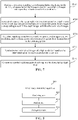
- the process of synthesizing the plurality of sparse lattice depth maps into a dense lattice depth map in step S420 may further include the following steps, as shown in FIG. 7 : Step S710: Perform a two-layer sampling on each sparse lattice depth map in the plurality of sparse lattice depth maps to obtain two sampling images corresponding to each sparse lattice depth map.
- a first layer sampling with a resolution of 640 ⁇ 480 and a second layer sampling with a resolution of 320 ⁇ 240 may be performed on a lattice depth map with a resolution of 640 ⁇ 480.
- two sampling images are obtained for each sparse lattice depth map.
- a sampling processing is performed on each lattice depth image in the plurality of lattice depth images through a plurality of sampling scales includes: performing a sampling processing on each lattice depth image in the plurality of lattice depth images through two sampling scales to obtain a sampling image of a first resolution and a sampling image of a second resolution corresponding to each lattice depth image, where the first resolution is less than or equal to a resolution of each lattice depth image.
- Step S720 Respectively convert the two sampling images corresponding to each sparse lattice depth map into point cloud images to obtain two point cloud images corresponding to each lattice depth image, and filter the point cloud images.
- the payment processing server may respectively convert two sampling images corresponding to each sparse lattice depth map into point cloud images based on the foregoing formula (2).
- Step S730 Calculate matching points between each two point cloud images of a low resolution, and determine poses between each two point cloud images based on the matching points.
- matching points can be calculated through a point cloud image corresponding to a sampling image with a resolution of 320 ⁇ 240, and then poses can be calculated based on the matching points.
- the matching points between the point cloud images may be calculated by a projection algorithm.
- Step S740 Synthesize two point cloud images of a high resolution based on the determined poses to obtain a dense point cloud map.
- the payment processing server may synthesize point cloud images respectively corresponding to sampling images with a resolution of 640 ⁇ 480 to obtain a dense point cloud map.
- Step S750 Convert the synthesized dense point cloud map into the dense lattice depth map.
- the dense point cloud map may be reversely converted into the dense lattice depth map based on the foregoing formula (2).
- step S430 a face recognition is performed by using the synthesized dense lattice depth map.
- a face payment processing may be performed based on the face recognition result. It can be seen that, in the technical solutions of the embodiments of this application, a low-power face recognition can be realized through the Dtof sensor.
- the dense lattice depth image is obtained by performing a fusion processing on the plurality of lattice depth images acquired by the Dtof sensor. Therefore, a high-precision face recognition may be realized through the dense lattice depth image, improving the accuracy of the face recognition.
- FIG. 8 is a block diagram of a face image processing apparatus according to an embodiment of this application.
- the face image processing apparatus may be disposed in a device with a computing processing function, for example, may be disposed in the payment processing server 103 shown in FIG. 1 .
- the face image processing apparatus 800 includes: an obtaining unit 802, a fusion unit 804, and a recognition unit 806.
- the obtaining unit 802 is configured to obtain a plurality of lattice depth images acquired by performing a depth image acquisition on a target face from different acquisition angles.
- the fusion unit 804 is configured to perform a fusion processing on the plurality of lattice depth images to obtain a dense lattice depth image.
- the recognition unit 806 is configured to perform a face recognition processing on the dense lattice depth image to obtain a face recognition result.
- the lattice depth images are acquired by a Dtof sensor.
- the Dtof sensor is connected to a micro motor.
- the obtaining unit 802 is configured to control the micro motor to drive the Dtof sensor to rotate, and obtain a plurality of lattice depth images acquired for the target face by the Dtof sensor driven by the micro motor.
- the fusion unit 804 includes: a processing unit 8041, configured to convert each lattice depth image in the plurality of lattice depth images into a corresponding point cloud image, and perform a fusion processing on a plurality of point cloud images to obtain a dense point cloud map; and a conversion unit 8042, configured to convert the dense point cloud map into the dense lattice depth image.
- the processing unit 8041 is configured to perform a sampling processing on each lattice depth image in the plurality of lattice depth images through a plurality of sampling scales to obtain a plurality of sampling images corresponding to each lattice depth image; respectively convert, for each lattice depth image in the plurality of lattice depth images, the plurality of sampling images corresponding to the corresponding lattice depth image into the point cloud images, to obtain a plurality of point cloud images corresponding to the corresponding lattice depth image, where the plurality of point cloud images corresponding to the corresponding lattice depth image include point cloud images of a first resolution and point cloud images of a second resolution, the first resolution being greater than the second resolution; register point cloud images of the second resolution respectively corresponding to the plurality of lattice depth images to obtain a registration result; and perform a fusion processing on point cloud images of the first resolution respectively corresponding to the plurality of lattice depth images based on the registration result to obtain the dense point cloud map
- the processing unit 8041 is configured to respectively convert, for each lattice depth image in the plurality of lattice depth images, the plurality of sampling images corresponding to the corresponding lattice depth image into the point cloud images based on a conversion relationship between the lattice depth images and point cloud coordinates.
- the processing unit 8041 is configured to perform a computing processing of matching points on the point cloud images of the second resolution respectively corresponding to the plurality of lattice depth images, to obtain matching points corresponding to the plurality of lattice depth images; and register the point cloud images of the second resolution respectively corresponding to the plurality of lattice depth images according to the matching points.
- the processing unit 8041 is configured to calculate, for point cloud images of the second resolution respectively corresponding to any two lattice depth images, a projection point of a point on one point cloud image onto another point cloud image by a projection algorithm, to obtain matching points between the any two lattice depth images; and determine matching points corresponding to the plurality of lattice depth images according to the matching points between the any two lattice depth images.
- the processing unit 8041 is configured to calculate poses among the plurality of lattice depth images based on the matching points; and perform a fusion processing on the point cloud images of the first resolution respectively corresponding to the plurality of lattice depth images based on the poses.
- the processing unit 8041 is configured to calculate poses between any two lattice depth images based on matching points between the any two lattice depth images; and calculate poses among the plurality of lattice depth images based on the poses between the any two lattice depth images.
- the processing unit 8041 is configured to perform a sampling processing on each lattice depth image in the plurality of lattice depth images through two sampling scales to obtain a sampling image of a first resolution and a sampling image of a second resolution corresponding to each lattice depth image, where the first resolution is less than or equal to a resolution of each lattice depth image.
- the face image processing apparatus 800 further includes: a payment unit 808, configured to perform, after obtaining the face recognition result, a face payment processing based on the face recognition result.
- Each module in the foregoing face image processing apparatus may be implemented in whole or in part by software, hardware, and a combination thereof.
- the network interface may be an Ethernet card, a wireless network card, or the like.
- the foregoing modules may be embedded in or independent of the processor in the server in the form of hardware, or may be stored in the memory in the server in the form of software, so that the processor can call and execute operations corresponding to the foregoing modules.
- a computer device including a memory and one or more processors.
- the memory stores computer-readable instructions, the computer-readable instructions, when executed by the one or more processors, causing the one or more processors to perform the steps of the face image processing method described above.
- the steps of the face image processing method may be the steps in the face image processing method in the various embodiments described above.
- one or more non-volatile readable storage media storing computer-readable instructions are provided, the computer-readable instructions, when executed by one or more processors, causing the one or more processors to perform the steps of the face image processing method described above.
- the steps of the face image processing method may be the steps in the face image processing method in the various embodiments described above.
- a computer program product or a computer program includes computer instructions, and the computer instructions are stored in a computer-readable storage medium.
- the processor of the computer device reads the computer instructions from the computer-readable storage medium.
- the processor executes the computer instructions, so that the computer device performs the steps of the various method embodiments described above.
- FIG. 9 is a schematic structural diagram of a computer system adapted to implement an electronic device according to an embodiment of this application.
- a computer system 900 of an electronic device shown in FIG. 9 is only an example, which is not to impose any limitation on the function and scope of use of the embodiments of this application.
- the computer system 900 includes a central processing unit (CPU) 901, which can execute various appropriate actions and processing according to a program stored in a read-only memory (ROM) 902 or a program loaded from a storage part 908 to a random access memory (RAM) 903, such as performing the methods described in the foregoing embodiments.
- the RAM 903 further stores various programs and data required for operating the system.
- the CPU 901, the ROM 902, and the RAM 903 are connected to each other through a bus 904.
- An input/output (I/O) interface 905 is also connected to the bus 904.
- the following components are connected to the I/O interface 905: an input part 906 including a keyboard, a mouse, or the like; an output part 907 including a cathode ray tube (CRT), a liquid crystal display (LCD), a speaker, or the like; a storage part 908 including a hard disk or the like; and a communication part 909 including a network interface card such as a local area network (LAN) card, a modem, or the like.
- the communication part 909 performs communication processing by using a network such as the Internet.
- a drive 910 is also connected to the I/O interface 905 as required.
- a removable medium 911 such as a disk, an optical disc, a magneto-optical disc, or a semiconductor memory, is installed on the drive 910 as required, so that a computer program read from the removable medium 911 is installed in the storage part 908 as required.
- an embodiment of this application includes a computer program product.
- the computer program product includes a computer program stored in a computer-readable medium.
- the computer program includes a computer program used for performing a method shown in the flowchart.
- the computer program may be downloaded and installed through the communication part 909 from a network, and/or installed from the removable medium 911.
- the computer-readable medium shown in the embodiments of this application may be a computer-readable signal medium or a computer-readable storage medium or any combination of the two.
- the computer-readable storage medium may be, for example, but is not limited to, an electrical, magnetic, optical, electromagnetic, infrared, or semiconductor system, apparatus, or device, or any combination thereof.
- a more specific example of the computer-readable storage medium may include but is not limited to: an electrical connection having one or more wires, a portable computer magnetic disk, a hard disk, a random access memory (RAM), a read-only memory (ROM), an erasable programmable read-only memory (EPROM), a flash memory, an optical fiber, a compact disk read-only memory (CD-ROM), an optical storage device, a magnetic storage device, or any appropriate combination thereof.
- the computer-readable storage medium may be any tangible medium containing or storing a program, and the program may be used by or used in combination with an instruction execution system, an apparatus, or a device.
- a computer-readable signal medium may include a data signal in a baseband or propagated as a part of a carrier wave, the data signal carrying a computer-readable computer program.
- a data signal propagated in such a way may assume a plurality of forms, including, but not limited to, an electromagnetic signal, an optical signal, or any appropriate combination thereof.
- the computer-readable signal medium may be further any computer-readable medium in addition to a computer-readable storage medium.
- the computer-readable medium may send, propagate, or transmit a program that is used by or used in combination with an instruction execution system, apparatus, or device.
- the computer program included in the computer-readable medium may be transmitted by using any suitable medium, including but not limited to: a wireless medium, a wire, or the like, or any suitable combination thereof.
- Each box in a flowchart or a block diagram may represent a module, a program segment, or a part of code.
- the module, the program segment, or the part of code includes one or more executable instructions used for implementing designated logic functions.
- functions annotated in boxes may alternatively occur in a sequence different from that annotated in an accompanying drawing. For example, actually two boxes shown in succession may be performed basically in parallel, and sometimes the two boxes may be performed in a reverse sequence. This is determined by a related function.
- Each box in a block diagram and/or a flowchart and a combination of boxes in the block diagram and/or the flowchart may be implemented by using a dedicated hardware-based system configured to perform a specified function or operation, or may be implemented by using a combination of dedicated hardware and a computer instruction.
- a related unit described in the embodiments of this application may be implemented in a software manner, or may be implemented in a hardware manner, and the unit described may also be set in a processor. Names of the units do not constitute a limitation on the units in a specific case.
- this application further provides a computer-readable medium.
- the computer-readable medium may be included in the electronic device described in the foregoing embodiments, or may exist alone and is not disposed in the electronic device.
- the computer-readable medium carries one or more programs, the one or more programs, when executed by the electronic device, causing the electronic device to implement the method described in the foregoing embodiments.
- the software product may be stored in a non-volatile storage medium (which may be a CD-ROM, a USB flash drive, a removable hard disk, or the like) or on the network, including several instructions for instructing a computing device (which may be a personal computer, a server, a touch terminal, a network device, or the like) to perform the methods according to the embodiments of this application.
- a non-volatile storage medium which may be a CD-ROM, a USB flash drive, a removable hard disk, or the like
- a computing device which may be a personal computer, a server, a touch terminal, a network device, or the like
Landscapes
- Engineering & Computer Science (AREA)
- Theoretical Computer Science (AREA)
- Physics & Mathematics (AREA)
- General Physics & Mathematics (AREA)
- Business, Economics & Management (AREA)
- Accounting & Taxation (AREA)
- Multimedia (AREA)
- Health & Medical Sciences (AREA)
- General Health & Medical Sciences (AREA)
- Oral & Maxillofacial Surgery (AREA)
- Human Computer Interaction (AREA)
- Computer Vision & Pattern Recognition (AREA)
- General Business, Economics & Management (AREA)
- Finance (AREA)
- Computer Security & Cryptography (AREA)
- Strategic Management (AREA)
- Evolutionary Computation (AREA)
- Artificial Intelligence (AREA)
- Data Mining & Analysis (AREA)
- Software Systems (AREA)
- Medical Informatics (AREA)
- Databases & Information Systems (AREA)
- Computing Systems (AREA)
- Life Sciences & Earth Sciences (AREA)
- Bioinformatics & Cheminformatics (AREA)
- Bioinformatics & Computational Biology (AREA)
- Evolutionary Biology (AREA)
- General Engineering & Computer Science (AREA)
- Image Processing (AREA)
Abstract
Description
- This application claims priority to
Chinese Patent Application No. 202010838648.1, entitled "FACE IMAGE PROCESSING METHOD AND APPARATUS, COMPUTER-READABLE MEDIUM, AND DEVICE" and filed with the National Intellectual Property Administration, PRC on August, 19, 2020 - This application relates to the field of computer and communication technologies, and specifically, to a face image processing method and apparatus, a computer-readable medium, and a device.
- Face recognition payment is a payment technology based on a face recognition system. The technology does not require wallets, credit cards, or mobile phones, and only needs to face a camera on a payment device when paying. After the camera collects consumer's facial information, the system automatically associates the consumer's facial information with a personal account, making the entire transaction process very convenient and fast.
- However, at present, a face area containing the consumer's face is cropped to obtain a to-be-recognized image, and then face recognition is performed on the to-be-recognized image to obtain the consumer's facial information. However, the precision of face recognition is not high when directly performing face recognition on the to-be-recognized image. Therefore, how to improve the precision of face recognition is a technical problem to be resolved urgently.
- Various embodiments of this application provide a face image processing method and apparatus, a computer-readable medium, and a device. Technical solutions are as follows:
- A face image processing method is provided, performed by a payment processing server, the method including: obtaining a plurality of lattice depth images acquired by performing a depth image acquisition on a target face from different acquisition angles; performing a fusion processing on the plurality of lattice depth images to obtain a dense lattice depth image; and performing a face recognition processing on the dense lattice depth image to obtain a face recognition result.
- A face image processing apparatus is provided, including: an obtaining unit, configured to obtain a plurality of lattice depth images acquired by performing a depth image acquisition on a target face from different acquisition angles;
- a fusion unit, configured to perform a fusion processing on the plurality of lattice depth images to obtain a dense lattice depth image; and
- a recognition unit, configured to perform a face recognition processing on the dense lattice depth image to obtain a face recognition result.
- In an embodiment, the lattice depth images are acquired by a Dtof sensor, the Dtof sensor being connected to a micro motor; and
the obtaining unit is configured to control the micro motor to drive the Dtof sensor to rotate, and obtain a plurality of lattice depth images acquired for the target face by the Dtof sensor driven by the micro motor. - In an embodiment, the fusion unit includes: a processing unit, configured to convert each lattice depth image in the plurality of lattice depth images into a corresponding point cloud image, and perform a fusion processing on a plurality of point cloud images to obtain a dense point cloud map; and
a conversion unit, configured to convert the dense point cloud map into the dense lattice depth image. - In an embodiment, the processing unit is configured to perform a sampling processing on each lattice depth image in the plurality of lattice depth images through a plurality of sampling scales to obtain a plurality of sampling images corresponding to each lattice depth image; respectively convert, for each lattice depth image in the plurality of lattice depth images, the plurality of sampling images corresponding to the corresponding lattice depth image into point cloud images, to obtain a plurality of point cloud images corresponding to the corresponding lattice depth image, where the plurality of point cloud images corresponding to the corresponding lattice depth image include point cloud images of a first resolution and point cloud images of a second resolution, the first resolution being greater than the second resolution; register point cloud images of the second resolution respectively corresponding to the plurality of lattice depth images to obtain a registration result; and perform a fusion processing on point cloud images of the first resolution respectively corresponding to the plurality of lattice depth images based on the registration result to obtain the dense point cloud map.
- In an embodiment, the processing unit is configured to respectively convert, for each lattice depth image in the plurality of lattice depth images, the plurality of sampling images corresponding to the corresponding lattice depth image into the point cloud images based on a conversion relationship between the lattice depth images and point cloud coordinates.
- In an embodiment, the processing unit is configured to perform a computing processing of matching points on the point cloud images of the second resolution respectively corresponding to the plurality of lattice depth images, to obtain matching points corresponding to the plurality of lattice depth images; and register the point cloud images of the second resolution respectively corresponding to the plurality of lattice depth images according to the matching points.
- In an embodiment, the processing unit is configured to calculate, for point cloud images of the second resolution respectively corresponding to any two lattice depth images, a projection point of a point on one point cloud image onto another point cloud image by a projection algorithm, to obtain matching points between the any two lattice depth images; and determine matching points corresponding to the plurality of lattice depth images according to the matching points between the any two lattice depth images.
- In an embodiment, the processing unit is configured to calculate poses among the plurality of lattice depth images based on the matching points; and perform a fusion processing on the point cloud images of the first resolution respectively corresponding to the plurality of lattice depth images based on the poses.
- In an embodiment, the processing unit is configured to calculate poses between any two lattice depth images based on matching points between the any two lattice depth images; and calculate poses among the plurality of lattice depth images based on the poses between the any two lattice depth images.
- In an embodiment, the processing unit is configured to perform a sampling processing on each lattice depth image in the plurality of lattice depth images through two sampling scales to obtain a sampling image of a first resolution and a sampling image of a second resolution corresponding to each lattice depth image, where the first resolution is less than or equal to a resolution of each lattice depth image.
- In an embodiment, the face image processing apparatus further includes: a payment unit, configured to perform a face payment processing based on the face recognition result after obtaining the face recognition result.
- A face-based payment device is provided, including: a Dtof sensor, configured to acquire lattice depth images of a face;
- a micro motor, connected to the Dtof sensor, and configured to drive the Dtof sensor to rotate to acquire the lattice depth images of the face from different angles; and
- a processor, electrically connected to the Dtof sensor, the processor being configured to receive the lattice depth images acquired by the Dtof sensor, and configured to perform the face image processing method described in the foregoing embodiments.
- One or more non-volatile readable storage media storing computer-readable instructions are provided, the computer-readable instructions, when executed by one or more processors, causing the one or more processors to perform the steps of the face image processing method described in the foregoing embodiments.
- An electronic device is provided, including a memory and one or more processors, the memory storing computer-readable instructions, the computer-readable instructions, when executed by the one or more processors, causing the one or more processors to perform the steps of the face image processing method described in the foregoing embodiments.
- A computer program product or a computer program is provided, the computer program product or the computer program including computer instructions, the computer instructions being stored in a computer-readable storage medium. A processor of a computer device reads the computer instructions from the computer-readable storage medium, and the processor executes the computer instructions, to cause the computer device to implement the face image processing method provided in the various optional embodiments described above.
-
-
FIG. 1 is a schematic diagram of an exemplary system architecture to which a technical solution according to an embodiment of this application is applicable. -
FIG. 2 is a flowchart of a face image processing method according to an embodiment of this application. -
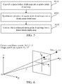
FIG. 3 is a flowchart of converting a plurality of lattice depth images into corresponding point cloud images and performing a fusion processing on the point cloud images to obtain a dense point cloud map according to an embodiment of this application. -
FIG. 4 is a flowchart of a face recognition method according to an embodiment of this application. -
FIG. 5 is a flowchart of synthesizing a plurality of sparse lattice depth maps into a dense lattice depth map according to an embodiment of this application. -
FIG. 6 is a schematic diagram of a conversion relationship between a camera coordinate system and an image coordinate system. -
FIG. 7 is a flowchart of synthesizing a plurality of sparse lattice depth maps into a dense lattice depth map according to an embodiment of this application. -
FIG. 8 is a block diagram of a face image processing apparatus according to an embodiment of this application. -
FIG. 9 is a schematic structural diagram of a computer system adapted to implement an electronic device according to an embodiment of this application. - "Plurality of" mentioned herein means two or more. And/or describes an association relationship for describing associated objects and represents that three relationships may exist. For example, A and/or B may represent the following three cases: Only A exists, both A and B exist, and only B exists. The character "/" generally indicates an "or" relationship between the associated obj ects.
- The solutions provided in the embodiments of this application relate to technologies such as computer vision of artificial intelligence, and are specifically described by using the following embodiments.
- In the embodiments of this application, a Dtof depth map technology may be adopted when collecting face images for recognition. The Dtof depth map technology is a technology for directly measuring time of flight and then converting the time of flight into a depth. Alternatively, a structured light depth map technology may also be adopted. The structured light depth map technology is a technology for realizing depth map calculation based on key steps such as calibration, projection acquisition, and decoding calculation by encoding structured light. Certainly, an Itof (indirect time-of-flight) depth map technology may also be adopted. The Itof depth map technology is a technology for indirectly measuring time of flight of light by measuring a phase offset and then converting the time of flight into a depth. However, compared with the Dtof depth map technology, the structured light depth map technology has higher costs, a lower integration, and a lower long-distance precision. In addition, compared with the Dtof depth map technology, the Itof depth map technology has a lower precision and a larger power consumption. Therefore, to reduce the power consumption in the face recognition process and improve the precision of face recognition, in the following embodiments of this application, the Dtof depth map technology is used as an example for a detailed description.
- As shown in
FIG. 1 , in anexemplary system architecture 100 of this application, apayment terminal 101, anetwork 102, and apayment processing server 103 may be included. Thenetwork 102 is configured to provide a medium of a communication link between thepayment terminal 101 and thepayment processing server 103. Thenetwork 102 may include various connection types, such as a wired communication link, a wireless communication link, or the like. - It is to be understood that the quantity of the
payment terminal 101, the quantity of thenetwork 102, and the quantity of thepayment processing server 103 inFIG. 1 are merely illustrative. Thepayment terminal 101 may include a tablet computer, a notebook computer, a personal computer (PC), a micro processing box, or other devices. Thepayment processing server 103 may be an independent physical server, may also be a server cluster or distributed system composed of a plurality of physical servers, and may also be a cloud server providing basic cloud computing services, such as a cloud service, a cloud database, cloud computing, a cloud function, cloud storage, a network service, cloud communication, a middleware service, a domain name service, a security service, a CDN, and a big data and artificial intelligence platform. Thepayment terminal 101 may be a smartphone, a tablet computer, a notebook computer, a desktop computer, a smart speaker, a smartwatch, or the like, but is not limited thereto. - In an embodiment of this application, a Dtof sensor is disposed on the
payment terminal 101. The Dtof sensor is connected to a micro motor. The micro motor can drive the Dtof sensor to rotate to acquire lattice depth images of a face from different angles. When face payment is required, prompt information of the face payment may be displayed on thepayment terminal 101, and then the Dtof sensor is driven to rotate by the micro motor to acquire a plurality of lattice depth images of the face. After acquiring the plurality of lattice depth images of the face, thepayment terminal 101 may send the plurality of lattice depth images to thepayment processing server 103 through thenetwork 102. Then, thepayment processing server 103 performs a fusion processing on the plurality of lattice depth images to obtain a dense lattice depth image. Further, a face recognition processing is performed on the obtained dense lattice depth image to obtain a face recognition result. After obtaining the face recognition result, thepayment processing server 103 may perform a payment processing based on the face recognition result. That is, the payment processing is performed based on the recognized face. It can be seen that, in the embodiments of this application, the dense lattice depth image is obtained by performing a fusion processing on the plurality of lattice depth images acquired by the Dtof sensor. Therefore, a high-precision face recognition may be realized through the dense lattice depth image, improving the accuracy of the face recognition, and the power consumption of the face recognition may also be reduced. - The face image processing method provided by the embodiments of this application is generally performed by the
payment processing server 103. Correspondingly, a face image processing apparatus is generally disposed in thepayment processing server 103. However, in other embodiments of this application, the payment device may also have functions similar to those of the payment processing server, thereby performing the face image processing method provided by the embodiments of this application. For example, after acquiring the plurality of lattice depth images of the face, thepayment terminal 101 may perform a fusion processing on the plurality of lattice depth images to obtain a dense lattice depth image. Further, a face recognition processing is performed on the obtained dense lattice depth image to obtain a face recognition result. After obtaining the face recognition result, thepayment terminal 101 may send the face recognition result to thepayment processing server 103, and then thepayment processing server 103 may perform a payment processing based on the face recognition result. - Implementation details of the technical solutions of the embodiments of this application are described below in detail.
-
FIG. 2 is a flowchart of a face image processing method according to an embodiment of this application. The face image processing method may be performed by a device with a computing processing function, for example, by thepayment processing server 103 shown inFIG. 1 . Referring toFIG. 2 , the face image processing method includes at least steps S210 to S230, which are described in detail below:
In step S210, a plurality of lattice depth images acquired by performing a depth image acquisition on a target face from different acquisition angles are obtained. - In an embodiment, the lattice depth images are acquired by a Dtof sensor. When the Dtof sensor performs a depth image acquisition on a target face from different acquisition angles, the face may be kept still, and then the images may be acquired by controlling the Dtof sensor to rotate. Alternatively, the images may be acquired by keeping the Dtof sensor still and prompting the user to move the face, or may be acquired by moving both the Dtof sensor and the face.
- Optionally, when the rotation of the Dtof sensor is realized, the Dtof sensor may be driven to rotate by a micro motor. The depth image acquisition of the target face from different acquisition angles may be realized by the slight rotation of the Dtof sensor. Certainly, the Dtof sensor may also be driven to rotate by other transmission mechanisms to realize the acquisition of the depth image of the face. When prompting the user to move the face to acquire the depth image, prompt information may be displayed on a display panel, or the user may be prompted to move the face by a speaker device issuing voice prompt information.
- In step S220, a fusion processing is performed on the plurality of lattice depth images to obtain a dense lattice depth image.
- In an embodiment, the process of performing a fusion processing on the plurality of lattice depth images by the payment processing server is to convert the plurality of lattice depth images into corresponding point cloud images, then perform a fusion processing on the point cloud images obtained through conversion to obtain a dense point cloud map, and then convert the dense point cloud map into a dense lattice depth image. The lattice depth image may also be referred to as a sparse lattice depth image. The point cloud image may also be referred to as a sparse point cloud image.
- In an embodiment, as shown in
FIG. 3 , the process of converting each lattice depth image in the plurality of lattice depth images into a corresponding point cloud image, and performing a fusion processing on the point cloud images to obtain a dense point cloud map may include the following steps S310 to step S340:
In step S310, a sampling processing is performed on each lattice depth image in the plurality of lattice depth images through a plurality of sampling scales to obtain a plurality of sampling images corresponding to each lattice depth image. - In an embodiment, the payment processing server may perform a sampling processing on each lattice depth image in the plurality of lattice depth images through two sampling scales to obtain a sampling image of a first resolution and a sampling image of a second resolution corresponding to each lattice depth image, where the first resolution is greater than the second resolution, and the first resolution is less than or equal to a resolution of each lattice depth image. Optionally, the first resolution may be equal to the resolution of each lattice depth image. In an embodiment, the sampling processing may be performed on each lattice depth image through three sampling scales or more sampling scales.
- In step S320, for each lattice depth image in the plurality of lattice depth images, the plurality of sampling images corresponding to the corresponding lattice depth image are converted into point cloud images to obtain a plurality of point cloud images corresponding to the corresponding lattice depth image. The plurality of point cloud images corresponding to the corresponding lattice depth image include point cloud images of a first resolution and point cloud images of a second resolution. The first resolution is greater than the second resolution.
- In an embodiment, that for each lattice depth image in the plurality of lattice depth images, the plurality of sampling images corresponding to the corresponding lattice depth image are converted into point cloud images includes: for each lattice depth image in the plurality of lattice depth images, based on a conversion relationship between the lattice depth images and point cloud coordinates, respectively converting the plurality of sampling images corresponding to the corresponding lattice depth image into the point cloud images.
- There is a correspondence between the lattice depth images and the point cloud coordinates. Therefore, the payment processing server may respectively convert, based on the conversion relationship between the lattice depth images and point cloud coordinates, the plurality of sampling images corresponding to each lattice depth image into the point cloud images.
- In step S330, point cloud images of the second resolution respectively corresponding to the plurality of lattice depth images are registered to obtain a registration result.
- In an embodiment, that the point cloud images of the second resolution respectively corresponding to the plurality of lattice depth images are registered includes: performing a computing processing of matching points on the point cloud images of the second resolution respectively corresponding to the plurality of lattice depth images, to obtain matching points corresponding to the plurality of lattice depth images; and registering the point cloud images of the second resolution respectively corresponding to the plurality of lattice depth images according to the matching points.
- The payment processing server may perform a computing processing of matching points on the point cloud images of the second resolution respectively corresponding to the plurality of lattice depth images, to obtain the matching points corresponding to the plurality of lattice depth images; and then register the point cloud images of the second resolution respectively corresponding to the plurality of lattice depth images according to the obtained matching points.
- In an embodiment, the performing a computing processing of matching points on the point cloud images of the second resolution respectively corresponding to the plurality of lattice depth images includes: calculating, for point cloud images of the second resolution respectively corresponding to any two lattice depth images, a projection point of a point on one point cloud image onto another point cloud image by a projection algorithm, to obtain matching points between the any two lattice depth images; and determining matching points corresponding to the plurality of lattice depth images according to the matching points between the any two lattice depth images.
- When calculating the matching points corresponding to the plurality of lattice depth images, the payment processing server may perform calculation by using two lattice depth images as a group, and then perform a combination to determine the matching points corresponding to the plurality of lattice depth images. Specifically, for point cloud images of the second resolution respectively corresponding to any two lattice depth images, a projection point of a point on one point cloud image onto another point cloud image may be calculated by the projection algorithm to obtain matching points between the two lattice depth images; and then matching points corresponding to the plurality of lattice depth images are determined according to the matching points between the two lattice depth images.
- In an embodiment, the plurality of lattice depth images may be grouped in pairs for calculation, to obtain the matching points between each two lattice depth images. The matching points corresponding to the plurality of lattice depth images are determined according to the matching points between each two lattice depth images. For example, the matching points between each two lattice depth images are taken as the matching points corresponding to the plurality of lattice depth images.
- Still referring to
FIG. 3 , in step S340, a fusion processing is performed on point cloud images of the first resolution respectively corresponding to the plurality of lattice depth images based on the registration result to obtain a dense point cloud map. - In an embodiment, that a fusion processing is performed on the point cloud images of the first resolution respectively corresponding to the plurality of lattice depth images based on the registration result includes: calculating poses among the plurality of lattice depth images based on the matching points; and performing a fusion processing on the point cloud images of the first resolution respectively corresponding to the plurality of lattice depth images based on the poses.
- When the fusion processing is performed on the point cloud images of the first resolution respectively corresponding to the plurality of lattice depth images based on the registration result, the payment processing server may calculate poses among the plurality of lattice depth images based on the matching points; and then perform the fusion processing on the point cloud images of the first resolution respectively corresponding to the plurality of lattice depth images based on the calculated poses among the plurality of lattice depth images.
- In an embodiment, the calculating poses among the plurality of lattice depth images based on the matching points includes: calculating poses between any two lattice depth images based on matching points between the any two lattice depth images; and calculating poses among the plurality of lattice depth images based on the poses between the any two lattice depth images.
- When calculating the poses among the plurality of lattice depth images, the payment processing server may group the lattice depth images in pairs for calculation, that is, calculating, according to matching points between two lattice depth images in each group, poses between the two lattice depth images; and then calculating the poses among the plurality of lattice depth images based on the poses between the two lattice depth images in each group.
- The technical solution of the embodiment shown in
FIG. 3 enables registration to be performed through point cloud images of a lower resolution (that is, the second resolution), improving the efficiency of image registration. Then, based on a registration result, a fusion processing is performed on the point cloud images of a higher resolution (that is, the first resolution) to obtain a dense point cloud map. Further, the dense point cloud map is converted into a dense lattice depth image, ensuring that the obtained dense lattice depth image has a higher resolution, which helps to improve the accuracy of the face recognition. - Still referring to
FIG. 2 , in step S230, a face recognition processing is performed on the dense lattice depth image obtained by the fusion processing to obtain a face recognition result. - In an embodiment, after obtaining the face recognition result, the payment processing server may perform a face payment processing based on the face recognition result. In this case, a face-based payment device in the embodiments of this application may include a Dtof sensor configured to acquire lattice depth images of a face, a micro motor connected to the Dtof sensor, and a processor electrically connected to the Dtof sensor. The micro motor is configured to drive the Dtof sensor to rotate to acquire the lattice depth images of the face from different angles. The processor is configured to receive the lattice depth images acquired by the Dtof sensor, and configured to perform the face recognition by the method described in the foregoing embodiments. Further, a low-power face recognition can be realized through the Dtof sensor. In addition, the dense lattice depth image is obtained by performing a fusion processing on the plurality of lattice depth images acquired by the Dtof sensor. Therefore, a high-precision face recognition may be realized through the dense lattice depth image, improving the accuracy of the face recognition.
- A detailed description of the technical solutions of the embodiments of this application is provided below with reference to
FIG. 4 to FIG. 7 . -
FIG. 4 is a flowchart of a face recognition method according to an embodiment of this application. The face recognition method may be performed by a device with a computing processing function. - Referring to
FIG. 4 , the face recognition method according to this embodiment of this application includes the following steps S410 to S430. In step S410, a micro motor is used to rotate a Dtof sensor to perform scanning to obtain a plurality of sparse lattice depth maps. In this step, by using the micro motor to rotate the Dtof sensor to perform scanning, the acquisition of a plurality of sparse lattice depth maps can be realized without the user's perception. In this way, not only the user experience can be improved, but also the costs of the product can be reduced. In addition, an accurate face recognition can be achieved through the plurality of sparse lattice depth maps. - In an embodiment, the lattice depth images are acquired by a Dtof sensor. The Dtof sensor is connected to a micro motor. That a plurality of lattice depth images acquired by the Dtof sensor by performing a depth image acquisition on a target face from different acquisition angles are obtained includes: controlling the micro motor to drive the Dtof sensor to rotate, and obtaining a plurality of lattice depth images acquired for the target face by the Dtof sensor driven by the micro motor.
- In step S420, the plurality of sparse lattice depth maps are synthesized into a dense lattice depth map.
- In an embodiment of this application, when the payment processing server synthesizes the plurality of sparse lattice depth maps into a dense lattice depth map, the flow shown in
FIG. 5 may be adopted, including the following steps S510 to S530, which are described in detail below:
In an embodiment, that a fusion processing is performed on the plurality of lattice depth images to obtain a dense lattice depth image includes: converting each lattice depth image in the plurality of lattice depth images into a corresponding point cloud image, and performing a fusion processing on a plurality of point cloud images to obtain a dense point cloud map; and converting the dense point cloud map into the dense lattice depth image. - In step S510, the sparse lattice depth map is converted into the sparse point cloud map.
- In an embodiment, the payment processing server may convert the sparse lattice depth map into the sparse point cloud map by a coordinate conversion formula between a depth map and a point cloud map.
- Specifically, as shown in
FIG. 6 , assuming that a camera coordinate system is O-XCYCZC, an image coordinate system is O1-XY, and a point in the image coordinate system to which a three-dimensional point M(xc , yc, zc ) in the camera coordinate system is mapped is m(x, y). Assuming that focal lengths of a camera on an x-axis and a y-axis are fx and fy respectively, and aperture centers of the camera are cx and cy , then the following formula (1) can be obtained according to the similarity principle of triangles:
- In fact, the aperture center of the camera is not the center of the image, and there is usually a deviation. For example, for a camera corresponding to a resolution of 640×480, intrinsic parameters of the camera are cx = 316.2, cy = 235.7, fx = 565.0, and fy = 566.3 respectively. Therefore, the obtained coordinate conversion relationship between the camera coordinate system and the image coordinate system is shown in the following formula (2):

- The points in the camera coordinate system are the points in the lattice depth map. If depth coordinates of the point cloud are not considered, the coordinates of the points in the image coordinate system are the coordinates of the points in the point cloud. Therefore, the sparse lattice depth maps can be converted into the sparse point cloud maps through the foregoing formula (2).
- Still referring to
FIG. 5 , in step S520, the plurality of sparse point cloud maps are synthesized into a dense point cloud map. - In an embodiment, when the payment processing server synthesizes the plurality of sparse point cloud maps into a dense point cloud map, two sparse point cloud maps may be used as a group to perform registration. For example, matching points between the two sparse point cloud maps may be calculated by a projection algorithm, and then pose transformation between the two sparse point cloud maps is determined based on the matching points. Further, after obtaining the poses, the plurality of sparse point cloud maps may be synthesized into a dense point cloud map based on the poses.
- In step S530, the synthesized dense point cloud map is converted into a dense lattice depth map.
- In an embodiment, the payment processing server may similarly reversely convert the dense point cloud map into the dense lattice depth map based on the foregoing formula (2).
- The technical solution of the embodiment shown in
FIG. 5 is to convert the sparse lattice depth maps into the sparse point cloud maps, then directly fuse the sparse point cloud maps to obtain the dense point cloud map, and then convert the dense point cloud map into the dense lattice depth map. - In an embodiment, the process of synthesizing the plurality of sparse lattice depth maps into a dense lattice depth map in step S420 may further include the following steps, as shown in
FIG. 7 :
Step S710: Perform a two-layer sampling on each sparse lattice depth map in the plurality of sparse lattice depth maps to obtain two sampling images corresponding to each sparse lattice depth map. - For example, a first layer sampling with a resolution of 640×480 and a second layer sampling with a resolution of 320×240 may be performed on a lattice depth map with a resolution of 640×480. In this way, two sampling images are obtained for each sparse lattice depth map.
- In an embodiment, that a sampling processing is performed on each lattice depth image in the plurality of lattice depth images through a plurality of sampling scales includes: performing a sampling processing on each lattice depth image in the plurality of lattice depth images through two sampling scales to obtain a sampling image of a first resolution and a sampling image of a second resolution corresponding to each lattice depth image, where the first resolution is less than or equal to a resolution of each lattice depth image.
- Step S720: Respectively convert the two sampling images corresponding to each sparse lattice depth map into point cloud images to obtain two point cloud images corresponding to each lattice depth image, and filter the point cloud images.
- In an embodiment, for each sparse lattice depth map in the plurality of sparse lattice depth maps, the payment processing server may respectively convert two sampling images corresponding to each sparse lattice depth map into point cloud images based on the foregoing formula (2).
- Step S730: Calculate matching points between each two point cloud images of a low resolution, and determine poses between each two point cloud images based on the matching points.
- In an embodiment, for example, if a first layer sampling with a resolution of 640×480 and a second layer sampling with a resolution of 320×240 are performed on a lattice depth map with a resolution of 640×480, matching points can be calculated through a point cloud image corresponding to a sampling image with a resolution of 320×240, and then poses can be calculated based on the matching points. Optionally, the matching points between the point cloud images may be calculated by a projection algorithm.
- Step S740: Synthesize two point cloud images of a high resolution based on the determined poses to obtain a dense point cloud map.
- In an embodiment, for example, if a first layer sampling with a resolution of 640×480 and a second layer sampling with a resolution of 320×240 are performed on a lattice depth map with a resolution of 640×480, after determining poses between each two point cloud images, the payment processing server may synthesize point cloud images respectively corresponding to sampling images with a resolution of 640×480 to obtain a dense point cloud map.
- Step S750: Convert the synthesized dense point cloud map into the dense lattice depth map.
- In an embodiment, the dense point cloud map may be reversely converted into the dense lattice depth map based on the foregoing formula (2).
- Still referring to
FIG. 4 , in step S430, a face recognition is performed by using the synthesized dense lattice depth map. - In an embodiment, after obtaining the face recognition result, a face payment processing may be performed based on the face recognition result. It can be seen that, in the technical solutions of the embodiments of this application, a low-power face recognition can be realized through the Dtof sensor. In addition, the dense lattice depth image is obtained by performing a fusion processing on the plurality of lattice depth images acquired by the Dtof sensor. Therefore, a high-precision face recognition may be realized through the dense lattice depth image, improving the accuracy of the face recognition.
- The following describes apparatus embodiments of this application, which can be used for performing the face image processing method in the foregoing embodiments of this application. For details not disclosed in the apparatus embodiments of this application, reference may be made to the foregoing embodiments of the face image processing method of this application.
-
FIG. 8 is a block diagram of a face image processing apparatus according to an embodiment of this application. The face image processing apparatus may be disposed in a device with a computing processing function, for example, may be disposed in thepayment processing server 103 shown inFIG. 1 . - Referring to
FIG. 8 , the faceimage processing apparatus 800 according to this embodiment of this application includes: an obtainingunit 802, afusion unit 804, and arecognition unit 806. - The obtaining
unit 802 is configured to obtain a plurality of lattice depth images acquired by performing a depth image acquisition on a target face from different acquisition angles. Thefusion unit 804 is configured to perform a fusion processing on the plurality of lattice depth images to obtain a dense lattice depth image. Therecognition unit 806 is configured to perform a face recognition processing on the dense lattice depth image to obtain a face recognition result. - In an embodiment, the lattice depth images are acquired by a Dtof sensor. The Dtof sensor is connected to a micro motor. The obtaining
unit 802 is configured to control the micro motor to drive the Dtof sensor to rotate, and obtain a plurality of lattice depth images acquired for the target face by the Dtof sensor driven by the micro motor. - In an embodiment, the
fusion unit 804 includes: a processing unit 8041, configured to convert each lattice depth image in the plurality of lattice depth images into a corresponding point cloud image, and perform a fusion processing on a plurality of point cloud images to obtain a dense point cloud map; and a conversion unit 8042, configured to convert the dense point cloud map into the dense lattice depth image. - In an embodiment, the processing unit 8041 is configured to perform a sampling processing on each lattice depth image in the plurality of lattice depth images through a plurality of sampling scales to obtain a plurality of sampling images corresponding to each lattice depth image; respectively convert, for each lattice depth image in the plurality of lattice depth images, the plurality of sampling images corresponding to the corresponding lattice depth image into the point cloud images, to obtain a plurality of point cloud images corresponding to the corresponding lattice depth image, where the plurality of point cloud images corresponding to the corresponding lattice depth image include point cloud images of a first resolution and point cloud images of a second resolution, the first resolution being greater than the second resolution; register point cloud images of the second resolution respectively corresponding to the plurality of lattice depth images to obtain a registration result; and perform a fusion processing on point cloud images of the first resolution respectively corresponding to the plurality of lattice depth images based on the registration result to obtain the dense point cloud map.
- In an embodiment, the processing unit 8041 is configured to respectively convert, for each lattice depth image in the plurality of lattice depth images, the plurality of sampling images corresponding to the corresponding lattice depth image into the point cloud images based on a conversion relationship between the lattice depth images and point cloud coordinates.
- In an embodiment, the processing unit 8041 is configured to perform a computing processing of matching points on the point cloud images of the second resolution respectively corresponding to the plurality of lattice depth images, to obtain matching points corresponding to the plurality of lattice depth images; and register the point cloud images of the second resolution respectively corresponding to the plurality of lattice depth images according to the matching points.
- In an embodiment, the processing unit 8041 is configured to calculate, for point cloud images of the second resolution respectively corresponding to any two lattice depth images, a projection point of a point on one point cloud image onto another point cloud image by a projection algorithm, to obtain matching points between the any two lattice depth images; and determine matching points corresponding to the plurality of lattice depth images according to the matching points between the any two lattice depth images.
- In an embodiment, the processing unit 8041 is configured to calculate poses among the plurality of lattice depth images based on the matching points; and perform a fusion processing on the point cloud images of the first resolution respectively corresponding to the plurality of lattice depth images based on the poses.
- In an embodiment, the processing unit 8041 is configured to calculate poses between any two lattice depth images based on matching points between the any two lattice depth images; and calculate poses among the plurality of lattice depth images based on the poses between the any two lattice depth images.
- In an embodiment, the processing unit 8041 is configured to perform a sampling processing on each lattice depth image in the plurality of lattice depth images through two sampling scales to obtain a sampling image of a first resolution and a sampling image of a second resolution corresponding to each lattice depth image, where the first resolution is less than or equal to a resolution of each lattice depth image.
- In an embodiment, based on the foregoing solutions, the face
image processing apparatus 800 further includes: a payment unit 808, configured to perform, after obtaining the face recognition result, a face payment processing based on the face recognition result. - Each module in the foregoing face image processing apparatus may be implemented in whole or in part by software, hardware, and a combination thereof. The network interface may be an Ethernet card, a wireless network card, or the like. The foregoing modules may be embedded in or independent of the processor in the server in the form of hardware, or may be stored in the memory in the server in the form of software, so that the processor can call and execute operations corresponding to the foregoing modules.
- In some embodiments, a computer device is provided, including a memory and one or more processors. The memory stores computer-readable instructions, the computer-readable instructions, when executed by the one or more processors, causing the one or more processors to perform the steps of the face image processing method described above. The steps of the face image processing method may be the steps in the face image processing method in the various embodiments described above.
- In some embodiments, one or more non-volatile readable storage media storing computer-readable instructions are provided, the computer-readable instructions, when executed by one or more processors, causing the one or more processors to perform the steps of the face image processing method described above. The steps of the face image processing method may be the steps in the face image processing method in the various embodiments described above.
- In some embodiments, a computer program product or a computer program is provided. The computer program product or the computer program includes computer instructions, and the computer instructions are stored in a computer-readable storage medium. The processor of the computer device reads the computer instructions from the computer-readable storage medium. The processor executes the computer instructions, so that the computer device performs the steps of the various method embodiments described above.
-
FIG. 9 is a schematic structural diagram of a computer system adapted to implement an electronic device according to an embodiment of this application. - A
computer system 900 of an electronic device shown inFIG. 9 is only an example, which is not to impose any limitation on the function and scope of use of the embodiments of this application. - As shown in
FIG. 9 , thecomputer system 900 includes a central processing unit (CPU) 901, which can execute various appropriate actions and processing according to a program stored in a read-only memory (ROM) 902 or a program loaded from astorage part 908 to a random access memory (RAM) 903, such as performing the methods described in the foregoing embodiments. TheRAM 903 further stores various programs and data required for operating the system. TheCPU 901, theROM 902, and theRAM 903 are connected to each other through abus 904. An input/output (I/O)interface 905 is also connected to thebus 904. - The following components are connected to the I/O interface 905: an
input part 906 including a keyboard, a mouse, or the like; anoutput part 907 including a cathode ray tube (CRT), a liquid crystal display (LCD), a speaker, or the like; astorage part 908 including a hard disk or the like; and acommunication part 909 including a network interface card such as a local area network (LAN) card, a modem, or the like. Thecommunication part 909 performs communication processing by using a network such as the Internet. Adrive 910 is also connected to the I/O interface 905 as required. Aremovable medium 911, such as a disk, an optical disc, a magneto-optical disc, or a semiconductor memory, is installed on thedrive 910 as required, so that a computer program read from theremovable medium 911 is installed in thestorage part 908 as required. - Particularly, according to an embodiment of this application, the processes described above by referring to the flowcharts may be implemented as computer software programs. For example, an embodiment of this application includes a computer program product. The computer program product includes a computer program stored in a computer-readable medium. The computer program includes a computer program used for performing a method shown in the flowchart. In such an embodiment, the computer program may be downloaded and installed through the
communication part 909 from a network, and/or installed from theremovable medium 911. When the computer program is executed by theCPU 901, the various functions defined in the system of this application are executed. - The computer-readable medium shown in the embodiments of this application may be a computer-readable signal medium or a computer-readable storage medium or any combination of the two. The computer-readable storage medium may be, for example, but is not limited to, an electrical, magnetic, optical, electromagnetic, infrared, or semiconductor system, apparatus, or device, or any combination thereof. A more specific example of the computer-readable storage medium may include but is not limited to: an electrical connection having one or more wires, a portable computer magnetic disk, a hard disk, a random access memory (RAM), a read-only memory (ROM), an erasable programmable read-only memory (EPROM), a flash memory, an optical fiber, a compact disk read-only memory (CD-ROM), an optical storage device, a magnetic storage device, or any appropriate combination thereof. In this application, the computer-readable storage medium may be any tangible medium containing or storing a program, and the program may be used by or used in combination with an instruction execution system, an apparatus, or a device. In this application, a computer-readable signal medium may include a data signal in a baseband or propagated as a part of a carrier wave, the data signal carrying a computer-readable computer program. A data signal propagated in such a way may assume a plurality of forms, including, but not limited to, an electromagnetic signal, an optical signal, or any appropriate combination thereof. The computer-readable signal medium may be further any computer-readable medium in addition to a computer-readable storage medium. The computer-readable medium may send, propagate, or transmit a program that is used by or used in combination with an instruction execution system, apparatus, or device. The computer program included in the computer-readable medium may be transmitted by using any suitable medium, including but not limited to: a wireless medium, a wire, or the like, or any suitable combination thereof.
- The flowcharts and block diagrams in the accompanying drawings illustrate possible system architectures, functions, and operations that may be implemented by a system, a method, and a computer program product according to various embodiments of this application. Each box in a flowchart or a block diagram may represent a module, a program segment, or a part of code. The module, the program segment, or the part of code includes one or more executable instructions used for implementing designated logic functions. In some implementations used as substitutes, functions annotated in boxes may alternatively occur in a sequence different from that annotated in an accompanying drawing. For example, actually two boxes shown in succession may be performed basically in parallel, and sometimes the two boxes may be performed in a reverse sequence. This is determined by a related function. Each box in a block diagram and/or a flowchart and a combination of boxes in the block diagram and/or the flowchart may be implemented by using a dedicated hardware-based system configured to perform a specified function or operation, or may be implemented by using a combination of dedicated hardware and a computer instruction.
- A related unit described in the embodiments of this application may be implemented in a software manner, or may be implemented in a hardware manner, and the unit described may also be set in a processor. Names of the units do not constitute a limitation on the units in a specific case.
- According to another aspect, this application further provides a computer-readable medium. The computer-readable medium may be included in the electronic device described in the foregoing embodiments, or may exist alone and is not disposed in the electronic device. The computer-readable medium carries one or more programs, the one or more programs, when executed by the electronic device, causing the electronic device to implement the method described in the foregoing embodiments.
- Although a plurality of modules or units of a device configured to perform actions are discussed in the foregoing detailed description, such division is not mandatory. Actually, according to the implementations of this application, the features and functions of two or more modules or units described above may be specifically implemented in one module or unit. Conversely, features and functions of one module or unit described above may be further divided into a plurality of modules or units for implementation.
- Through the descriptions of the foregoing implementations, a person skilled in the art easily understands that the exemplary implementations described herein may be implemented through software, or may be implemented through software located in combination with necessary hardware. Therefore, the technical solutions of the embodiments of this application may be implemented in the form of a software product. The software product may be stored in a non-volatile storage medium (which may be a CD-ROM, a USB flash drive, a removable hard disk, or the like) or on the network, including several instructions for instructing a computing device (which may be a personal computer, a server, a touch terminal, a network device, or the like) to perform the methods according to the embodiments of this application.
Claims (20)
- A face image processing method, performed by a payment processing server, the method comprising:obtaining a plurality of lattice depth images acquired by performing a depth image acquisition on a target face from different acquisition angles;performing a fusion processing on the plurality of lattice depth images to obtain a dense lattice depth image; andperforming a face recognition processing on the dense lattice depth image to obtain a face recognition result.
- The face image processing method according to claim 1, wherein the lattice depth images are acquired by a Dtof sensor, the Dtof sensor being connected to a micro motor; and the obtaining a plurality of lattice depth images acquired by performing a depth image acquisition on a target face from different acquisition angles comprises:
controlling the micro motor to drive the Dtof sensor to rotate, and obtaining a plurality of lattice depth images acquired for the target face by the Dtof sensor driven by the micro motor. - The face image processing method according to claim 1, wherein the performing a fusion processing on the plurality of lattice depth images to obtain a dense lattice depth image comprises:converting each lattice depth image in the plurality of lattice depth images into a corresponding point cloud image, and performing a fusion processing on a plurality of point cloud images to obtain a dense point cloud map; andconverting the dense point cloud map into the dense lattice depth image.
- The face image processing method according to claim 3, wherein the converting each lattice depth image in the plurality of lattice depth images into a corresponding point cloud image, and performing a fusion processing on a plurality of point cloud images to obtain a dense point cloud map comprises:performing a sampling processing on each lattice depth image in the plurality of lattice depth images through a plurality of sampling scales to obtain a plurality of sampling images corresponding to each lattice depth image;respectively converting, for each lattice depth image in the plurality of lattice depth images, the plurality of sampling images corresponding to the corresponding lattice depth image into the point cloud images, to obtain a plurality of point cloud images corresponding to the corresponding lattice depth image, wherein the plurality of point cloud images corresponding to the corresponding lattice depth image comprise point cloud images of a first resolution and point cloud images of a second resolution, the first resolution being greater than the second resolution;registering point cloud images of the second resolution respectively corresponding to the plurality of lattice depth images to obtain a registration result; andperforming a fusion processing on point cloud images of the first resolution respectively corresponding to the plurality of lattice depth images based on the registration result to obtain the dense point cloud map.
- The face image processing method according to claim 4, wherein the respectively converting, for each lattice depth image in the plurality of lattice depth images, the plurality of sampling images corresponding to the corresponding lattice depth image into the point cloud images comprises:
respectively converting, for each lattice depth image in the plurality of lattice depth images, the plurality of sampling images corresponding to the corresponding lattice depth image into the point cloud images based on a conversion relationship between the lattice depth images and point cloud coordinates. - The face image processing method according to claim 4, wherein the registering the point cloud images of the second resolution respectively corresponding to the plurality of lattice depth images comprises:performing a computing processing of matching points on the point cloud images of the second resolution respectively corresponding to the plurality of lattice depth images, to obtain matching points corresponding to the plurality of lattice depth images; andregistering the point cloud images of the second resolution respectively corresponding to the plurality of lattice depth images according to the matching points.
- The face image processing method according to claim 6, wherein the performing a computing processing of matching points on the point cloud images of the second resolution respectively corresponding to the plurality of lattice depth images comprises:calculating, for point cloud images of the second resolution respectively corresponding to any two lattice depth images, a projection point of a point on one point cloud image onto another point cloud image by a projection algorithm, to obtain matching points between the any two lattice depth images; anddetermining matching points corresponding to the plurality of lattice depth images according to the matching points between the any two lattice depth images.
- The face image processing method according to claim 6, wherein the performing a fusion processing on the point cloud images of the first resolution respectively corresponding to the plurality of lattice depth images based on the registration result comprises:calculating poses among the plurality of lattice depth images based on the matching points; andperforming a fusion processing on the point cloud images of the first resolution respectively corresponding to the plurality of lattice depth images based on the poses.
- The face image processing method according to claim 8, wherein the calculating poses among the plurality of lattice depth images based on the matching points comprises:calculating poses between any two lattice depth images based on matching points between the any two lattice depth images; andcalculating poses among the plurality of lattice depth images based on the poses between the any two lattice depth images.
- The face image processing method according to claim 4, wherein the performing a sampling processing on each lattice depth image in the plurality of lattice depth images through a plurality of sampling scales to obtain a plurality of sampling images corresponding to each lattice depth image comprises:
performing a sampling processing on each lattice depth image in the plurality of lattice depth images through two sampling scales to obtain a sampling image of a first resolution and a sampling image of a second resolution corresponding to each lattice depth image, wherein the first resolution is less than or equal to a resolution of each lattice depth image. - The face image processing method according to any one of claims 1 to 10, wherein after obtaining the face recognition result, the processing method further comprises: performing a face payment processing based on the face recognition result.
- A face image processing apparatus, comprising:an obtaining unit, configured to obtain a plurality of lattice depth images acquired by performing a depth image acquisition on a target face from different acquisition angles;a fusion unit, configured to perform a fusion processing on the plurality of lattice depth images to obtain a dense lattice depth image; anda recognition unit, configured to perform a face recognition processing on the dense lattice depth image to obtain a face recognition result.
- The apparatus according to claim 12, wherein the fusion unit comprises:a processing unit, configured to convert each lattice depth image in the plurality of lattice depth images into a corresponding point cloud image, and perform a fusion processing on a plurality of point cloud images to obtain a dense point cloud map; anda conversion unit, configured to convert the dense point cloud map into the dense lattice depth image.
- The apparatus according to claim 13, wherein the processing unit is configured to perform a sampling processing on each lattice depth image in the plurality of lattice depth images through a plurality of sampling scales to obtain a plurality of sampling images corresponding to each lattice depth image; respectively convert, for each lattice depth image in the plurality of lattice depth images, the plurality of sampling images corresponding to the corresponding lattice depth image into the point cloud images, to obtain a plurality of point cloud images corresponding to the corresponding lattice depth image, wherein the plurality of point cloud images corresponding to the corresponding lattice depth image comprise point cloud images of a first resolution and point cloud images of a second resolution, the first resolution being greater than the second resolution; register point cloud images of the second resolution respectively corresponding to the plurality of lattice depth images to obtain a registration result; and perform a fusion processing on point cloud images of the first resolution respectively corresponding to the plurality of lattice depth images based on the registration result to obtain the dense point cloud map.
- The apparatus according to claim 14, wherein the processing unit is configured to respectively convert, for each lattice depth image in the plurality of lattice depth images, the plurality of sampling images corresponding to the corresponding lattice depth image into the point cloud images based on a conversion relationship between the lattice depth images and point cloud coordinates.
- The apparatus according to claim 14, wherein the processing unit is configured to perform a computing processing of matching points on the point cloud images of the second resolution respectively corresponding to the plurality of lattice depth images, to obtain matching points corresponding to the plurality of lattice depth images; and register the point cloud images of the second resolution respectively corresponding to the plurality of lattice depth images according to the matching points.
- The apparatus according to claim 16, wherein the processing unit is configured to calculate, for point cloud images of the second resolution respectively corresponding to any two lattice depth images, a projection point of a point on one point cloud image onto another point cloud image by a projection algorithm, to obtain matching points between the any two lattice depth images; and determine matching points corresponding to the plurality of lattice depth images according to the matching points between the any two lattice depth images.
- A face-based payment device, comprising:a Dtof sensor, configured to acquire lattice depth images of a face;a micro motor, connected to the Dtof sensor, and configured to drive the Dtof sensor to rotate to acquire the lattice depth images of the face from different angles; anda processor, electrically connected to the Dtof sensor, the processor being configured to receive the lattice depth images acquired by the Dtof sensor, and configured to perform the face image processing method according to any one of claims 1 to 11.
- One or more non-volatile readable storage media storing computer-readable instructions, the computer-readable instructions, when executed by one or more processors, causing the one or more processors to perform the face image processing method according to any one of claims 1 to 11.
- An electronic device, comprising a memory and one or more processors, the memory storing computer-readable instructions, the computer-readable instructions, when executed by the one or more processors, causing the one or more processors to perform the face image processing method according to any one of claims 1 to 11.
Applications Claiming Priority (2)
| Application Number | Priority Date | Filing Date | Title |
|---|---|---|---|
| CN202010838648.1A CN114170640B (en) | 2020-08-19 | 2020-08-19 | Face image processing method, device, computer readable medium and equipment |
| PCT/CN2021/102644 WO2022037253A1 (en) | 2020-08-19 | 2021-06-28 | Facial image processing method, device, computer-readable medium, and equipment |
Publications (2)
| Publication Number | Publication Date |
|---|---|
| EP4123502A1 true EP4123502A1 (en) | 2023-01-25 |
| EP4123502A4 EP4123502A4 (en) | 2023-11-22 |
Family
ID=80323381
Family Applications (1)
| Application Number | Title | Priority Date | Filing Date |
|---|---|---|---|
| EP21857349.1A Pending EP4123502A4 (en) | 2020-08-19 | 2021-06-28 | Facial image processing method, device, computer-readable medium, and equipment |
Country Status (4)
| Country | Link |
|---|---|
| US (2) | US12437579B2 (en) |
| EP (1) | EP4123502A4 (en) |
| CN (1) | CN114170640B (en) |
| WO (1) | WO2022037253A1 (en) |
Family Cites Families (20)
| Publication number | Priority date | Publication date | Assignee | Title |
|---|---|---|---|---|
| WO2013020248A1 (en) * | 2011-08-09 | 2013-02-14 | Intel Corporation | Image-based multi-view 3d face generation |
| US8989455B2 (en) * | 2012-02-05 | 2015-03-24 | Apple Inc. | Enhanced face detection using depth information |
| US10848731B2 (en) * | 2012-02-24 | 2020-11-24 | Matterport, Inc. | Capturing and aligning panoramic image and depth data |
| RU2012154657A (en) | 2012-12-17 | 2014-06-27 | ЭлЭсАй Корпорейшн | METHODS AND DEVICE FOR COMBINING IMAGES WITH DEPTH GENERATED USING DIFFERENT METHODS FOR FORMING IMAGES WITH DEPTH |
| CN104346608B (en) * | 2013-07-26 | 2017-09-08 | 株式会社理光 | Sparse depth figure denseization method and apparatus |
| WO2015122079A1 (en) * | 2014-02-14 | 2015-08-20 | 株式会社ソニー・コンピュータエンタテインメント | Information processing device and information processing method |
| US10282591B2 (en) * | 2015-08-24 | 2019-05-07 | Qualcomm Incorporated | Systems and methods for depth map sampling |
| CN107506696A (en) * | 2017-07-29 | 2017-12-22 | 广东欧珀移动通信有限公司 | Anti-fake processing method and related product |
| US10657363B2 (en) * | 2017-10-26 | 2020-05-19 | Motorola Mobility Llc | Method and devices for authenticating a user by image, depth, and thermal detection |
| CN107633165B (en) * | 2017-10-26 | 2021-11-19 | 奥比中光科技集团股份有限公司 | 3D face identity authentication method and device |
| CN108319901B (en) * | 2018-01-17 | 2019-08-27 | 百度在线网络技术(北京)有限公司 | Biopsy method, device, computer equipment and the readable medium of face |
| CN108764024B (en) * | 2018-04-09 | 2020-03-24 | 平安科技(深圳)有限公司 | Device and method for generating face recognition model and computer readable storage medium |
| CN108769508B (en) * | 2018-04-28 | 2019-06-28 | Oppo广东移动通信有限公司 | Data processing method, apparatus, computer-readable storage medium and electronic device |
| CN114817895A (en) * | 2018-05-29 | 2022-07-29 | Oppo广东移动通信有限公司 | Verification template generation method and generation system, terminal and computer equipment |
| CN110579749A (en) * | 2018-06-11 | 2019-12-17 | 视锐光科技股份有限公司 | Time-of-flight ranging device and method for recognizing images |
| CN110738078A (en) * | 2018-07-19 | 2020-01-31 | 青岛海信移动通信技术股份有限公司 | A face recognition method and terminal device |
| CN109635539B (en) * | 2018-10-30 | 2022-10-14 | 荣耀终端有限公司 | Face recognition method and electronic equipment |
| CN109816791B (en) | 2019-01-31 | 2020-04-28 | 北京字节跳动网络技术有限公司 | Method and apparatus for generating information |
| CN110738730B (en) * | 2019-10-15 | 2023-07-18 | 业成科技(成都)有限公司 | Point cloud matching method, device, computer equipment and storage medium |
| CN111242097B (en) * | 2020-02-27 | 2023-04-18 | 腾讯科技(深圳)有限公司 | Face recognition method and device, computer readable medium and electronic equipment |
-
2020
- 2020-08-19 CN CN202010838648.1A patent/CN114170640B/en active Active
-
2021
- 2021-06-28 WO PCT/CN2021/102644 patent/WO2022037253A1/en not_active Ceased
- 2021-06-28 EP EP21857349.1A patent/EP4123502A4/en active Pending
-
2022
- 2022-08-29 US US17/897,587 patent/US12437579B2/en active Active
-
2025
- 2025-05-27 US US19/220,041 patent/US20250285466A1/en active Pending
Also Published As
| Publication number | Publication date |
|---|---|
| US20250285466A1 (en) | 2025-09-11 |
| US20220415082A1 (en) | 2022-12-29 |
| EP4123502A4 (en) | 2023-11-22 |
| CN114170640A (en) | 2022-03-11 |
| US12437579B2 (en) | 2025-10-07 |
| WO2022037253A1 (en) | 2022-02-24 |
| CN114170640B (en) | 2024-02-02 |
Similar Documents
| Publication | Publication Date | Title |
|---|---|---|
| EP4116462A2 (en) | Method and apparatus of processing image, electronic device, storage medium and program product | |
| EP3767519B1 (en) | Graphic code recognition method and apparatus, and terminal, and storage medium | |
| WO2021098454A1 (en) | Region of concern detection method and apparatus, and readable storage medium and terminal device | |
| EP3971685B1 (en) | Interactive control method and apparatus, electronic device and storage medium | |
| WO2022170742A1 (en) | Target detection method and apparatus, electronic device and storage medium | |
| US10970938B2 (en) | Method and apparatus for generating 3D information | |
| CN109508681A (en) | The method and apparatus for generating human body critical point detection model | |
| CN113077548A (en) | Collision detection method, device, equipment and storage medium for object | |
| CN109754464B (en) | Method and apparatus for generating information | |
| CN113947147A (en) | Training method and positioning method of target map model and related devices | |
| US20240311285A1 (en) | Testing control method and apparatus for application, and electronic device and storage medium | |
| EP4123595A2 (en) | Method and apparatus of rectifying text image, training method and apparatus, electronic device, and medium | |
| US11881044B2 (en) | Method and apparatus for processing image, device and storage medium | |
| CN113313114B (en) | Certificate information acquisition method, device, equipment and storage medium | |
| CN111125283A (en) | Electronic map construction method, device, computer equipment and storage medium | |
| CN114186007A (en) | High-precision map generation method and device, electronic equipment and storage medium | |
| US20230169680A1 (en) | Beijing baidu netcom science technology co., ltd. | |
| US12175705B2 (en) | Method of detecting collision of objects, device, and storage medium | |
| CN114723640A (en) | Obstacle information generation method and device, electronic equipment and computer readable medium | |
| CN114550236A (en) | Image recognition and training method, device, equipment and storage medium of model thereof | |
| WO2024041623A1 (en) | Special effect map generation method and apparatus, device, and storage medium | |
| CN115409981A (en) | Image processing method, apparatus, device, and medium | |
| CN116071527A (en) | Object processing method, device, storage medium and electronic equipment | |
| EP4123502A1 (en) | Facial image processing method, device, computer-readable medium, and equipment | |
| WO2024109646A1 (en) | Image rendering method and apparatus, device, and storage medium |
Legal Events
| Date | Code | Title | Description |
|---|---|---|---|
| STAA | Information on the status of an ep patent application or granted ep patent |
Free format text: STATUS: THE INTERNATIONAL PUBLICATION HAS BEEN MADE |
|
| PUAI | Public reference made under article 153(3) epc to a published international application that has entered the european phase |
Free format text: ORIGINAL CODE: 0009012 |
|
| STAA | Information on the status of an ep patent application or granted ep patent |
Free format text: STATUS: REQUEST FOR EXAMINATION WAS MADE |
|
| 17P | Request for examination filed |
Effective date: 20221019 |
|
| AK | Designated contracting states |
Kind code of ref document: A1 Designated state(s): AL AT BE BG CH CY CZ DE DK EE ES FI FR GB GR HR HU IE IS IT LI LT LU LV MC MK MT NL NO PL PT RO RS SE SI SK SM TR |
|
| REG | Reference to a national code |
Ref country code: DE Ref legal event code: R079 Free format text: PREVIOUS MAIN CLASS: G06K0009000000 Ipc: G06V0010800000 |
|
| A4 | Supplementary search report drawn up and despatched |
Effective date: 20231025 |
|
| DAV | Request for validation of the european patent (deleted) | ||
| DAX | Request for extension of the european patent (deleted) | ||
| RIC1 | Information provided on ipc code assigned before grant |
Ipc: G06V 40/16 20220101ALI20231019BHEP Ipc: G06V 10/80 20220101AFI20231019BHEP |
|
| STAA | Information on the status of an ep patent application or granted ep patent |
Free format text: STATUS: EXAMINATION IS IN PROGRESS |
|
| 17Q | First examination report despatched |
Effective date: 20250827 |
|
| GRAP | Despatch of communication of intention to grant a patent |
Free format text: ORIGINAL CODE: EPIDOSNIGR1 |
|
| STAA | Information on the status of an ep patent application or granted ep patent |
Free format text: STATUS: GRANT OF PATENT IS INTENDED |