EP4123412A1 - Power conversion device - Google Patents
Power conversion device Download PDFInfo
- Publication number
- EP4123412A1 EP4123412A1 EP20925218.8A EP20925218A EP4123412A1 EP 4123412 A1 EP4123412 A1 EP 4123412A1 EP 20925218 A EP20925218 A EP 20925218A EP 4123412 A1 EP4123412 A1 EP 4123412A1
- Authority
- EP
- European Patent Office
- Prior art keywords
- current
- value
- voltage
- upper limit
- compensation
- Prior art date
- Legal status (The legal status is an assumption and is not a legal conclusion. Google has not performed a legal analysis and makes no representation as to the accuracy of the status listed.)
- Pending
Links
Images










Classifications
-
- H—ELECTRICITY
- H02—GENERATION; CONVERSION OR DISTRIBUTION OF ELECTRIC POWER
- H02M—APPARATUS FOR CONVERSION BETWEEN AC AND AC, BETWEEN AC AND DC, OR BETWEEN DC AND DC, AND FOR USE WITH MAINS OR SIMILAR POWER SUPPLY SYSTEMS; CONVERSION OF DC OR AC INPUT POWER INTO SURGE OUTPUT POWER; CONTROL OR REGULATION THEREOF
- H02M7/00—Conversion of AC power input into DC power output; Conversion of DC power input into AC power output
- H02M7/42—Conversion of DC power input into AC power output without possibility of reversal
- H02M7/44—Conversion of DC power input into AC power output without possibility of reversal by static converters
- H02M7/48—Conversion of DC power input into AC power output without possibility of reversal by static converters using discharge tubes with control electrode or semiconductor devices with control electrode
- H02M7/53—Conversion of DC power input into AC power output without possibility of reversal by static converters using discharge tubes with control electrode or semiconductor devices with control electrode using devices of a triode or transistor type requiring continuous application of a control signal
- H02M7/537—Conversion of DC power input into AC power output without possibility of reversal by static converters using discharge tubes with control electrode or semiconductor devices with control electrode using devices of a triode or transistor type requiring continuous application of a control signal using semiconductor devices only, e.g. single switched pulse inverters
- H02M7/539—Conversion of DC power input into AC power output without possibility of reversal by static converters using discharge tubes with control electrode or semiconductor devices with control electrode using devices of a triode or transistor type requiring continuous application of a control signal using semiconductor devices only, e.g. single switched pulse inverters with automatic control of output wave form or frequency
-
- H—ELECTRICITY
- H02—GENERATION; CONVERSION OR DISTRIBUTION OF ELECTRIC POWER
- H02J—ELECTRIC POWER NETWORKS; CIRCUIT ARRANGEMENTS OR SYSTEMS FOR SUPPLYING OR DISTRIBUTING ELECTRIC POWER; SYSTEMS FOR STORING ELECTRIC ENERGY
- H02J3/00—Circuit arrangements for AC mains or AC distribution networks
- H02J3/18—Arrangements for adjusting, eliminating or compensating reactive power in networks
- H02J3/1821—Arrangements for adjusting, eliminating or compensating reactive power in networks using shunt compensators
- H02J3/1835—Arrangements for adjusting, eliminating or compensating reactive power in networks using shunt compensators with stepless control
- H02J3/1842—Arrangements for adjusting, eliminating or compensating reactive power in networks using shunt compensators with stepless control having reactive elements actively controlled by bridge converters, e.g. active filters or static compensators [STATCOM]
-
- H—ELECTRICITY
- H02—GENERATION; CONVERSION OR DISTRIBUTION OF ELECTRIC POWER
- H02J—ELECTRIC POWER NETWORKS; CIRCUIT ARRANGEMENTS OR SYSTEMS FOR SUPPLYING OR DISTRIBUTING ELECTRIC POWER; SYSTEMS FOR STORING ELECTRIC ENERGY
- H02J3/00—Circuit arrangements for AC mains or AC distribution networks
- H02J3/01—Arrangements for reducing harmonics or ripples
-
- H—ELECTRICITY
- H02—GENERATION; CONVERSION OR DISTRIBUTION OF ELECTRIC POWER
- H02M—APPARATUS FOR CONVERSION BETWEEN AC AND AC, BETWEEN AC AND DC, OR BETWEEN DC AND DC, AND FOR USE WITH MAINS OR SIMILAR POWER SUPPLY SYSTEMS; CONVERSION OF DC OR AC INPUT POWER INTO SURGE OUTPUT POWER; CONTROL OR REGULATION THEREOF
- H02M1/00—Details of apparatus for conversion
- H02M1/12—Arrangements for reducing harmonics from AC input or output
-
- H—ELECTRICITY
- H02—GENERATION; CONVERSION OR DISTRIBUTION OF ELECTRIC POWER
- H02M—APPARATUS FOR CONVERSION BETWEEN AC AND AC, BETWEEN AC AND DC, OR BETWEEN DC AND DC, AND FOR USE WITH MAINS OR SIMILAR POWER SUPPLY SYSTEMS; CONVERSION OF DC OR AC INPUT POWER INTO SURGE OUTPUT POWER; CONTROL OR REGULATION THEREOF
- H02M7/00—Conversion of AC power input into DC power output; Conversion of DC power input into AC power output
- H02M7/42—Conversion of DC power input into AC power output without possibility of reversal
- H02M7/44—Conversion of DC power input into AC power output without possibility of reversal by static converters
- H02M7/48—Conversion of DC power input into AC power output without possibility of reversal by static converters using discharge tubes with control electrode or semiconductor devices with control electrode
- H02M7/483—Converters with outputs that each can have more than two voltages levels
- H02M7/4835—Converters with outputs that each can have more than two voltages levels comprising two or more cells, each including a switchable capacitor, the capacitors having a nominal charge voltage which corresponds to a given fraction of the input voltage, and the capacitors being selectively connected in series to determine the instantaneous output voltage
-
- Y—GENERAL TAGGING OF NEW TECHNOLOGICAL DEVELOPMENTS; GENERAL TAGGING OF CROSS-SECTIONAL TECHNOLOGIES SPANNING OVER SEVERAL SECTIONS OF THE IPC; TECHNICAL SUBJECTS COVERED BY FORMER USPC CROSS-REFERENCE ART COLLECTIONS [XRACs] AND DIGESTS
- Y02—TECHNOLOGIES OR APPLICATIONS FOR MITIGATION OR ADAPTATION AGAINST CLIMATE CHANGE
- Y02E—REDUCTION OF GREENHOUSE GAS [GHG] EMISSIONS, RELATED TO ENERGY GENERATION, TRANSMISSION OR DISTRIBUTION
- Y02E40/00—Technologies for an efficient electrical power generation, transmission or distribution
- Y02E40/10—Flexible AC transmission systems [FACTS]
-
- Y—GENERAL TAGGING OF NEW TECHNOLOGICAL DEVELOPMENTS; GENERAL TAGGING OF CROSS-SECTIONAL TECHNOLOGIES SPANNING OVER SEVERAL SECTIONS OF THE IPC; TECHNICAL SUBJECTS COVERED BY FORMER USPC CROSS-REFERENCE ART COLLECTIONS [XRACs] AND DIGESTS
- Y02—TECHNOLOGIES OR APPLICATIONS FOR MITIGATION OR ADAPTATION AGAINST CLIMATE CHANGE
- Y02E—REDUCTION OF GREENHOUSE GAS [GHG] EMISSIONS, RELATED TO ENERGY GENERATION, TRANSMISSION OR DISTRIBUTION
- Y02E40/00—Technologies for an efficient electrical power generation, transmission or distribution
- Y02E40/40—Arrangements for reducing harmonics
Definitions
- the present invention relates to a power conversion device.
- a power conversion device In an AC grid to which a load is connected, a power conversion device is connected for compensating for harmonic currents.
- harmonic detection means provided for each harmonic order detects a harmonic component in load current separately on a harmonic-order basis, and a compensation current command value for each harmonic is generated to perform output control of the power conversion device.
- the compensation ratio can be easily set, and a compensation gain and a compensation capacitance limiter can be set individually for each order, whereby it is possible to compensate for only a harmonic for a specific order (see, for example, Patent Document 1).
- Patent Document 1 Japanese Laid-Open Patent Publication JP 5- 049 172 A
- harmonic compensation can be performed by setting a limit individually for each harmonic order, but in some cases, voltage and current that the power conversion device can output cannot be sufficiently used.
- the present invention has been made to solve the above problem, and an object of the present invention is to provide a power conversion device that effectively performs harmonic compensation for each harmonic order while promoting usage of voltage and current that the power conversion device can output.
- a power conversion device includes: a power converter connected to an AC grid to which a load is connected; and a control circuit for performing output control of the power converter.
- the control circuit includes a harmonic compensation unit for compensating for harmonic current contained in load current by compensation current, and controls the compensation current in output current of the power converter.
- the harmonic compensation unit includes a current command generation unit and a limit coefficient calculation unit.
- the current command generation unit generates a compensation current desired value for each of a plurality of frequency components, and corrects each compensation current desired value using a corresponding limit coefficient, to generate a compensation current command for each frequency component.
- the limit coefficient calculation unit calculates each limit coefficient, on the basis of the compensation current desired value for each of the plurality of frequency components, and maximum voltage and maximum current that the power converter is able to output.
- the power conversion device makes it possible to effectively perform harmonic compensation for each harmonic order while promoting usage of voltage and current that the power conversion device can output.
- FIG. 1 is a block diagram showing a schematic configuration of a power conversion device according to Embodiment 1.
- a power conversion device 100 is connected to the AC grid 1, in parallel to the load 2.
- the power conversion device 100 includes a power converter 10 and a control circuit 20 for performing output control of the power converter 10, and the power converter 10 is connected to the AC grid 1 via a transformer 11.
- a voltage detector 3 and current detectors 4, 5 are provided for detecting voltage and currents at respective parts.
- the voltage detector 3 detects interconnection point voltage Vs (Vsu, Vsv, Vsw) which is voltage of the AC grid 1 interconnected with the power converter 10.
- the current detector 4 detects load current iload (iloadu, iloadv, iloadw) flowing from the AC grid 1 to the load 2, and the current detector 5 detects output current i (iu, iv, iw) outputted from the power converter 10 to the AC grid 1.
- the control circuit 20 performs switching control of switching elements in the power converter 10 on the basis of input information (interconnection point voltage Vs, load current iload, output current i) from the voltage detector 3 and the current detectors 4, 5, thereby performing output control of the power converter 10.
- the control circuit 20 includes an active power control unit 21, a reactive power control unit 22, a harmonic compensation unit 23, a current control unit 24, and a pulse width modulation (PWM) control unit 25.
- PWM pulse width modulation
- harmonics fundamental positive-phase-sequence component
- fundamental negative-phase-sequence component frequency components other than a fundamental positive-phase-sequence component, i.e., including a fundamental negative-phase-sequence component, are treated as harmonics.
- the active power control unit 21 and the reactive power control unit 22 generate an active current command id1p and a reactive current command iq1p as a first current command for the fundamental positive-phase-sequence component.
- the active power control unit 21 and the reactive power control unit 22 each receive values of interconnection point voltage Vs and output current i from the voltage detector 3 and the current detector 5. Then, the active power control unit 21 generates a d-axis current command as the active current command id1p for the fundamental positive-phase-sequence component on the basis of active power of the AC grid 1.
- the reactive power control unit 22 generates a q-axis current command as the reactive current command iq1p for the fundamental positive-phase-sequence component on the basis of reactive power of the AC grid 1.
- the harmonic compensation unit 23 includes a current command generation unit 30 and a limit coefficient calculation unit 40, and generates compensation current commands 31 for compensating for a plurality of frequency components that are harmonic currents by compensation currents.
- the current command generation unit 30 receives a value of the load current iload from the current detector 4 and a limit coefficient K generated for each frequency component by the limit coefficient calculation unit 40. Then, the current command generation unit 30 generates a compensation current desired value 32 for each of the plurality of frequency components on the basis of the load current iload, and corrects the compensation current desired value 32 using the limit coefficient K, to generate the compensation current command 31.
- the limit coefficient calculation unit 40 receives the active current command id1p and the reactive current command iq1p from the active power control unit 21 and the reactive power control unit 22, and the compensation current desired values 32 from the current command generation unit 30, and generates the limit coefficient K for each frequency component on the basis of the received values.
- the current control unit 24 receives the active current command id1p and the reactive current command iq1p from the active power control unit 21 and the reactive power control unit 22, and the compensation current commands 31 from the harmonic compensation unit 23, and generates a voltage command 24a on the basis of an output current command obtained by adding the received values.
- the PWM control unit 25 performs comparison using a carrier wave, to generate a gate signal 25a for switching elements in the power converter 10.
- FIG. 2 shows an example of a circuit configuration of the power converter 10.
- the power converter 10 is configured as a modular multilevel converter (MMC) of a double-star-connection type.
- the power converter 10 includes a plurality of converter cells 12 connected in series in each of upper and lower arms for each of three phases connected by double star connection which is an example of star connection, and includes arm reactors Lp, Ln on the positive side and the negative side.
- the power converter may have a circuit configuration of a power converter 10A shown in FIG. 3 .
- the power converter 10A is configured as a MMC of a delta-connection type.
- the power converter 10A includes a plurality of converter cells 12 connected in series in each of arms for each of three phases connected by delta connection, and includes arm reactors L.
- the power converter may have a circuit configuration of a power converter 10B shown in FIG. 4 .
- the power converter 10B is configured as a MMC of a single-star-connection type which is another example of star connection.
- the power converter 10B includes a plurality of converter cells 12 connected in series in each of arms for each of three phases connected by single star connection, and includes arm reactors L.
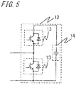
- FIG. 5 shows an example of a circuit configuration of the converter cell 12 in the power converter 10, 10A.
- the converter cell 12 is configured as a half-bridge circuit having two switching elements 13 to which diodes are connected in antiparallel, and a DC capacitor 14.
- the switching elements 13 are self-turn-off switching elements such as insulated-gate bipolar transistors (IGBT), for example.
- IGBT insulated-gate bipolar transistors
- a connection point between the two switching elements 13 and a DC terminal on the negative side are used as output ends, and two kinds of voltages, i.e., zero voltage and voltage across the DC capacitor 14 are outputted through switching of the switching elements 13.
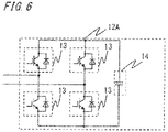
- the converter cell may have a circuit configuration of a converter cell 12A shown in FIG. 6 .
- the converter cell 12A is configured as a full-bridge circuit in which two legs each formed by series-connection of two switching elements 13 to which diodes are connected in antiparallel are connected in parallel with a DC capacitor 14.
- a connection point between the two switching elements 13 in each leg is used as an output end, and three kinds of voltages, i.e., zero voltage and positive and negative voltages across the DC capacitor 14 are outputted through switching of the switching elements 13.
- the power converter of the power conversion device 100 may have a circuit configuration of a power converter 10C shown in FIG. 7 .
- the power converter 10C is configured as a three-phase 2-level inverter in which three legs each formed by series connection of two switching elements 13 to which diodes are connected in antiparallel are connected in parallel with the DC capacitor 14. A connection point between the two switching elements 13 in each leg is used as an output end for each phase, and positive or negative voltage of the DC capacitor 14 is outputted for each phase through switching of the switching elements 13.
- the power conversion device 100 is used for a static synchronous compensator (STATCOM), an active filter, a high voltage direct current (HVDC) system for performing high-voltage DC power transmission, or the like.
- STATCOM static synchronous compensator
- HVDC high voltage direct current
- the power converter 10 configured as the MMC of a double-star-connection type and the power converter 10C configured as a three-phase 2-level inverter are used for an active filter, a STATCOM, a HVDC system, or the like.
- the active filter is a device for compensating for a harmonic component in the AC grid 1
- the STATCOM is a device for compensating for reactive power in the AC grid 1.
- the HVDC system is used for a grid of which the power transmission distance is long, and is a system in which power of an AC grid is forward converted to high-voltage DC power to be transmitted and then the DC power is inversely converted to AC power to be transmitted to another AC grid.
- the power converter 10A configured as the MMC of a delta-connection type is used for a distribution-STATCOM (D-STATCOM) for power distribution.
- D-STATCOM distribution-STATCOM
- the D-STATCOM performs reactive power compensation in a low-order grid close to a load.
- the power converter 10B configured as the MMC of a single-star-connection type is used for an active filter, a STATCOM, or the like.
- the power conversion device 100 is used for a device such as the STATCOM or the HVDC system that outputs a fundamental positive-phase-sequence component with highest priority given thereto, it is necessary to perform harmonic compensation while considering the fundamental positive-phase-sequence component outputted from the power converter 10.
- voltage that the power converter 10 can output is limited, it is necessary to appropriately set a limiter for compensation current included in the output current i of the power converter 10, also for preventing overmodulation.
- the power conversion device 100 outputs a fundamental positive-phase-sequence component and also compensates for harmonics with a priority set for each frequency component.
- FIG. 8 shows a configuration of the current command generation unit 30 of the harmonic compensation unit 23.
- the current command generation unit 30 includes a plurality of coordinate conversion units 33 that perform 3-phase/2-phase rotational coordinate conversion to extract a plurality of frequency components that are harmonic compensation targets, on the basis of the load current iload, and further includes a plurality of filters 34 and a plurality of multipliers 35.
- the three-phase load currents iload are subjected to rotational coordinate conversion by each of the plurality of coordinate conversion units 33, to be converted to DC currents for the plurality of frequency components.
- the plurality of coordinate conversion units 33 are set with different phases for coordinate conversion. For example, in a case of performing conversion to dq-axis currents idln, iq1n of a fundamental negative-phase-sequence component, coordinate conversion is performed with a negative fundamental component phase, and in a case of performing conversion to dq-axis currents id5p, iq5p of a fifth-order positive-phase-sequence component, coordinate conversion is performed with a positive fifth-order component phase.
- the fundamental negative-phase-sequence component, the fifth-order positive-phase-sequence component, a fifth-order negative-phase-sequence component, ..., a kth-order positive-phase-sequence component, and a kth-order negative-phase-sequence component are compensation targets, and dq-axis currents (id1n, iq1n), (id5p, iq5p), (id5n, iq5n), ..., (idkp, iqkp), and (idkn, iqkn) are generated.
- the dq-axis currents generated for each frequency component pass the filter 34 by which harmonic components are removed from DC current so that only the frequency component that is the compensation target is extracted.
- the compensation current desired values 32 i.e., (id1nf, iq1nf), (id5pf, iq5pf), (id5nf, iq5nf), ..., (idkpf, iqkpf), and (idknf, iqknf) are generated.
- the compensation current desired value 32 for each frequency component is multiplied by the limit coefficient K (K1n, K5p, K5n, ..., Kkp, and Kkn) generated for each frequency component by the limit coefficient calculation unit 40.
- the compensation current commands 31, i.e., (id1n ⁇ , iq1n ⁇ ), (id5p ⁇ , iq5p ⁇ ), (id5n ⁇ , iq5n ⁇ ), ..., (idkp ⁇ , iqkp ⁇ ), and (idkn ⁇ , iqkn ⁇ ) are generated.
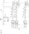
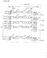
- FIG. 9 shows a configuration of the limit coefficient calculation unit 40 of the harmonic compensation unit 23.
- the limit coefficient calculation unit 40 includes a voltage limitation value generation unit 50, a current limitation value generation unit 60, and a coefficient calculating unit 70.
- the limit coefficient calculation unit 40 receives the active current command id1p and the reactive current command iq1p from the active power control unit 21 and the reactive power control unit 22, and the compensation current desired values 32 from the current command generation unit 30, and generates the limit coefficients K (K1n, K5p, K5n, ..., Kkp, and Kkn) for the respective frequency components on the basis of the received values.
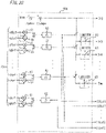
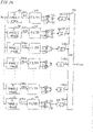
- FIG. 10 shows a configuration of the voltage limitation value generation unit 50 in the limit coefficient calculation unit 40
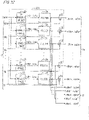
- FIG. 11 shows a configuration of the current limitation value generation unit 60 in the limit coefficient calculation unit 40
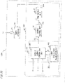
- FIG. 12 shows a configuration of the coefficient calculating unit 70 in the limit coefficient calculation unit 40.
- a priority of harmonic compensation is set for each of the plurality of frequency components, and in the limit coefficient calculation unit 40, the voltage limitation value generation unit 50 and the current limitation value generation unit 60 generate voltage upper limit values Vh1 to Vhm and current upper limit values Ih1 to Ihm for the respective frequency components, in the order of the priorities.
- a grid voltage maximum value Vsmax is subtracted from maximum voltage Vmax that the power converter 10 can output, thereby calculating voltage Vhmax that can be used for control of the power converter 10.
- the voltage limitation value generation unit 50 receives the active current command id1p and the reactive current command iq1p, and compensation current desired values 32a ((id1nf, iq1nf), (id5pf, iq5pf), (id5nf, iq5nf), ..., (idkpf, iqkpf)) excluding the kth-order negative-phase-sequence component having the lowest priority among the compensation current desired values 32 from the current command generation unit 30.
- the received d-axis and q-axis currents of each frequency component are squared by multipliers 51, and a square root of a sum obtained by adding the squared values is calculated by a square root calculator 52, thereby generating current amplitude values
- each current amplitude value is multiplied by a constant corresponding to the order number of the current and a fundamental impedance XL of a reactor in the transformer 11, thereby calculating voltage needed for outputting each current amplitude value, i.e., voltage to be allocated for each frequency component.
- the voltage limitation value generation unit 50 subtracts the voltage to be allocated for the fundamental positive-phase-sequence component from the voltage Vhmax, and then performs limiter processing for making a negative value be zero by a limiter 55, thereby calculating the voltage upper limit value Vh1 for the frequency component for which harmonic compensation is performed with the priority set at the first rank, in this case, the fundamental negative-phase-sequence component.
- the voltage to be allocated for the fundamental negative-phase-sequence component is subtracted, and the resultant value is similarly subjected to limiter processing, thus calculating the voltage upper limit value Vh2 for the frequency component of which the priority is at the second rank, in this case, the fifth-order positive-phase-sequence component.
- the voltage to be allocated for the frequency component is calculated, and this voltage is subtracted from the voltage upper limit value before limiter processing, to calculate the voltage upper limit value for the frequency component of which the priority is at the next rank.
- the voltage upper limit values Vh1, Vh2, Vh3, Vh4, ..., Vhm are generated in the order of priorities from the first rank.
- the generated voltage upper limit values are inputted to the coefficient calculating unit 70.
- the voltage value inputted to the limiter 55 is a negative value
- the output voltage of the power converter 10 has already exceeded the usable voltage, and therefore the voltage value is made to be zero by limiter processing and calculation of voltage upper limit values is not performed for the subsequent frequency components.
- the current limitation value generation unit 60 receives the active current command id1p and the reactive current command iq1p, and the compensation current desired values 32 ((id1nf, iq1nf), (id5pf, iq5pf), (id5nf, iq5nf), ..., (idkpf, iqkpf), and (idknf, iqknf)) from the current command generation unit 30.
- the d-axis and q-axis currents are squared by multipliers 61, and a square root of a sum obtained by adding the squared values is calculated by a square root calculator 62, thereby generating current amplitude values
- the current amplitude values are currents to be allocated for the respective frequency components.
- the current limitation value generation unit 60 subtracts the current amplitude value
- which is the current to be allocated for the fundamental negative-phase-sequence component is subtracted, and the resultant value is similarly subjected to limiter processing, thus calculating the current upper limit value Ih2 for the frequency component of which the priority is at the second rank, in this case, the fifth-order positive-phase-sequence component.
- the current (current amplitude value) to be allocated for the frequency component is calculated, and this current is subtracted from the current upper limit value before limiter processing, to calculate the current upper limit value for the frequency component of which the priority is at the next rank.
- the current limitation value generation unit 60 generates the current upper limit values Ih1, Ih2, Ih3, Ih4, ..., Ihm for the respective frequency components that are the compensation targets, in the order of priorities from the first rank. Then, the generated current upper limit values Ih1, Ih2, Ih3, Ih4, ..., Ihm and the generated current amplitude values
- the current value inputted to the limiter 63 is a negative value
- the output current of the power converter 10 has already exceeded the usable current, and therefore the current value is made to be zero by limiter processing and calculation of current upper limit values is not performed for the subsequent frequency components.
- limiter processing is not performed after the current amplitude value
- the coefficient calculating unit 70 receives the voltage upper limit values Vh1, Vh2, Vh3, Vh4, ..., Vhm, the current upper limit values Ih1, Ih2, Ih3, Ih4, ..., Ihm, and the current amplitude values
- the limit coefficient is calculated using the voltage upper limit value, the current upper limit value, and the current amplitude value. For example, for the fundamental negative-phase-sequence component of which the priority is at the first rank, the fundamental impedance XL of the reactor in the transformer 11 is multiplied by a constant corresponding to the order number (in this case, 1) at a constant multiplier 71, thereby calculating an impedance corresponding to the order number. Then, the voltage upper limit value Vh1 is divided by the calculated impedance at a divider 72, thereby calculating a first current value Ih1a which is a current limitation value based on the voltage upper limit value Vh1.
- are inputted to a minimum value extractor 73, and the minimum value extractor 73 extracts the minimum value among the three current values. This minimum value is divided by the current amplitude value
- the minimum values are extracted among the first current values Ih2a, ..., Ihma calculated from the voltage upper limit values Vh2, ..., Vhm and the impedances XL based on the frequencies, the current upper limit values Ih2, ..., Ihm, and the current amplitude values
- the compensation current desired values 32 for respective frequency components are multiplied by the limit coefficients K (K1n, K5p, ..., Kkn) generated as described above, that is, the compensation current desired values 32 are corrected using the limit coefficients K, whereby the compensation current commands 31 are generated.
- the harmonic compensation unit 23 in the control circuit 20 generates the compensation current desired value 32 for each of the plurality of frequency components on the basis of the load current iload, and calculates each limit coefficient K on the basis of the compensation current desired value 32, and the maximum voltage Vmax and the maximum current Imax that the power converter 10 can output. Then, each compensation current desired value 32 is corrected using the corresponding limit coefficient K, thereby generating the compensation current command 31 for each frequency component.
- the limit coefficient can be calculated individually in accordance with the order number of the compensation current, and thus it is possible to effectively perform harmonic compensation for each harmonic order.
- the limit coefficients can be calculated in real time in accordance with the operation condition of the power conversion device 100 and thus it is possible to perform control with high reliability and high accuracy.
- the voltage upper limit value Vh1 and the current upper limit value Ih1 are calculated, the minimum value is extracted among the first current value Ih1a based on the voltage upper limit value Vh1, the current upper limit value Ih1, and the current amplitude value
- the compensation current command 31 such that the usable voltage and current are not exceeded and can be sufficiently used, for each frequency component that is the compensation target.
- a priority is set for each frequency component that is the compensation target, and the voltage upper limit value (e.g., Vh1) and the current upper limit value (e.g., Ih1) are calculated in a descending order of the priorities.
- Vh1 and Ih1 are calculated in a descending order of the priorities.
- the harmonic compensation unit 23 calculates the voltage upper limit value (Vh1) and the current upper limit value (Ih1) for the frequency component of which the priority is at the first rank, on the basis of the maximum voltage Vmax and the maximum current Imax that the power converter 10 can output and the first current command (active current command id1p and reactive current command iq1p) for the fundamental positive-phase-sequence component.
- the harmonic compensation unit 23 calculates voltage and current to be allocated for the frequency component, and subtracts the calculated voltage and current from the voltage upper limit value (e.g., Vh1) and the current upper limit value (e.g., Ih1), respectively, thereby calculating the voltage upper limit value (Vh2) and the current upper limit value (Ih2) for the frequency component of which the priority is at the next rank (e.g., second rank).
- Vh1 voltage upper limit value
- Ih1 current upper limit value
- the voltage upper limit values e.g., Vh1
- the current upper limit values e.g., Ih1
- the priority of harmonic compensation is set at the first rank.
- the compensation current command 31 can be generated in the same manner and the same effects are obtained.
- the fundamental impedance XL is the impedance in the transformer 11, but impedances of the reactors L, Lp, Ln in the power converter 10 may be added thereto.
- the harmonic compensation unit 23 generates the compensation current desired value 32 for each of the plurality of frequency components on the basis of the load current iload and generates the compensation current command 31.
- the compensation current desired value 32 may be generated from another control system. For example, on the basis of the interconnection point voltage Vs, the compensation current desired value 32 may be generated so as to reduce a harmonic component of the interconnection point voltage Vs.
- Embodiment 1 the case where priorities of harmonic compensation are different among a plurality of frequency components, has been shown.
- Embodiment 2 a case where priorities are set at the same rank among a plurality of frequency components, will be described below.
- a schematic configuration of the power conversion device 100 is the same as that in the above Embodiment 1 shown in FIG. 1 , and while a fundamental positive-phase-sequence component is outputted, harmonic compensation is performed for each frequency component.
- the harmonic compensation unit 23 includes a current command generation unit 30A and a limit coefficient calculation unit 40A, and generates the compensation current commands 31 for compensating for harmonic currents by compensation currents.
- a priority of harmonic compensation for the fundamental negative-phase-sequence component is set at the first rank, and priorities for the other components are all set at the same rank.
- the current command generation unit 30A receives the value of the load current iload from the current detector 4 and the limit coefficient K generated for each frequency component by the limit coefficient calculation unit 40A. Then, the current command generation unit 30A generates the compensation current desired value 32 for each of the plurality of frequency components on the basis of the load current iload, and corrects the compensation current desired value 32 using the limit coefficient K, to generate the compensation current command 31.
- FIG. 13 shows a configuration of the current command generation unit 30A according to Embodiment 2
- FIG. 14 shows a schematic configuration of the limit coefficient calculation unit 40A.
- the current command generation unit 30A receives the value of the load current iload and the limit coefficient K (K1n, Kh) generated for each frequency component by the limit coefficient calculation unit 40A.
- K K1n, Kh
- the limit coefficients Kh for the frequency components other than the fundamental negative-phase-sequence component are all equal to each other.
- the current command generation unit 30A includes the plurality of coordinate conversion units 33 that perform 3-phase/2-phase rotational coordinate conversion to extract a plurality of frequency components that are harmonic compensation targets, on the basis of the load current iload, and further includes the plurality of filters 34 and the plurality of multipliers 35.
- the three-phase load currents iload are subjected to rotational coordinate conversion by each of the plurality of coordinate conversion units 33, to be converted to DC currents for the plurality of frequency components.
- the plurality of coordinate conversion units 33 are set with different phases for coordinate conversion. For example, in a case of performing conversion to the dq-axis currents idln, iq1n of the fundamental negative-phase-sequence component, coordinate conversion is performed with a negative fundamental component phase, and in a case of performing conversion to the dq-axis currents id5p, iq5p of the fifth-order positive-phase-sequence component, coordinate conversion is performed with a positive fifth-order component phase.
- the fundamental negative-phase-sequence component, the fifth-order positive-phase-sequence component, the fifth-order negative-phase-sequence component, ..., the kth-order positive-phase-sequence component, and the kth-order negative-phase-sequence component are compensation targets, and dq-axis currents (id1n, iq1n), (id5p, iq5p), (id5n, iq5n), ..., (idkp, iqkp), (idkn, iqkn) are generated.
- the dq-axis currents generated for each frequency component pass the filter 34 by which harmonic components are removed from DC current so that only the frequency component that is the compensation target is extracted.
- the compensation current desired values 32 i.e., (id1nf, iq1nf), (id5pf, iq5pf), (id5nf, iq5nf), ..., (idkpf, iqkpf), (idknf, iqknf) are generated.
- the compensation current desired value 32 for each frequency component is multiplied by the limit coefficient K (K1n, Kh) generated for each frequency component by the limit coefficient calculation unit 40A.
- the compensation current commands 31, i.e., (id1n ⁇ , iq1n ⁇ ), (id5p*, iq5p*), (id5n*, iq5n*), ..., (idkp*, iqkp*), and (idkn*, iqkn*) are generated.
- the limit coefficients K (K1n, Kh) generated for the respective frequency components are the same except for the fundamental negative-phase-sequence component, and therefore two kinds of limit coefficients are used.
- FIG. 15 shows a detailed configuration of the limit coefficient calculation unit 40A.
- the limit coefficient calculation unit 40A receives the active current command id1p and the reactive current command iq1p , and the compensation current desired values 32 ((id1nf, iq1nf), (id5pf, iq5pf), (id5nf, iq5nf), ..., (idkpf, iqkpf), and (idknf, iqknf)) from the current command generation unit 30A.
- the received d-axis and q-axis currents of each frequency component are squared by multipliers 81, and a square root of a sum obtained by adding the squared values is calculated by a square root calculator 82, thereby generating current amplitude values
- the limit coefficient calculation unit 40A subtracts the grid voltage maximum value Vsmax from the maximum voltage Vmax that the power converter 10 can output, thereby calculating the voltage Vhmax that can be used for control of the power converter 10.
- of the fundamental positive-phase-sequence component is multiplied by the fundamental impedance XL of the reactor in the transformer 11, thereby calculating voltage needed for outputting the current amplitude value
- the limit coefficient calculation unit 40A subtracts the voltage to be allocated for the fundamental positive-phase-sequence component from the voltage Vhmax, thereby calculating the voltage upper limit value Vh1 for the frequency component for which harmonic compensation is performed with the priority set at the first rank, in this case, the fundamental negative-phase-sequence component.
- the voltage upper limit value Vh1 is divided by the fundamental impedance XL at a divider 84, thereby calculating a first current value Ih1b which is a current limitation value based on the voltage upper limit value Vh1.
- the limit coefficient calculation unit 40A subtracts the current amplitude value
- of the fundamental negative-phase-sequence component as the second current value are inputted to a minimum value extractor 85, and the minimum value extractor 85 extracts the minimum value among the three current values.
- This minimum value is divided by the current amplitude value
- the limit coefficient Kh for the frequency component group of which the priorities are at the second rank or below is calculated as follows.
- of the fundamental positive-phase-sequence component and the fundamental negative-phase-sequence component is multiplied by the fundamental impedance XL of the reactor in the transformer 11, at a constant multiplier 91, thereby calculating voltage needed for outputting the current amplitude value
- the limit coefficient calculation unit 40A subtracts the voltage to be allocated for the fundamental positive-phase-sequence component and the fundamental negative-phase-sequence component from the voltage Vhmax, thereby calculating a voltage upper limit value Vhh for the frequency component group of which the priorities are at the second rank or below. Then, the voltage upper limit value Vhh is divided by the fundamental impedance XL at a divider 92, thereby calculating a current limitation value 92a based on the voltage upper limit value Vhh.
- an amplitude sum Ih which is the total sum of these amplitude values is calculated as the second current value, by a total sum calculator 87.
- are multiplied by constants corresponding to the respective order numbers at constant multipliers 88, and the total sum thereof is calculated as a third current value Iha by a total sum calculator 89.
- the third current value Iha is the total sum of the current amplitude values imparted with weights based on the respective frequencies.
- a value 90a obtained by dividing the amplitude sum Ih (second current value) by the third current value Iha at a divider 90 is multiplied by the current limitation value 92a based on the voltage upper limit value Vhh at a multiplier 93, thereby calculating a first current value Ihha which is a current limitation value based on the voltage upper limit value Vhh for the frequency component group of which the priorities are at the second rank or below.
- which are currents to be respectively allocated for the fundamental positive-phase-sequence component and the fundamental negative-phase-sequence component are sequentially subtracted from the maximum current Imax that the power converter 10 can output, thereby calculating a current upper limit value Ihh for the frequency component group of which the priorities are at the second rank or below.
- the calculated first current value Ihha, the calculated current upper limit value Ihh, and the calculated amplitude sum Ih (second current value) are inputted to a minimum value extractor 94, and the minimum value extractor 94 extracts the minimum value among the three current values. This minimum value is divided by the amplitude sum Ih at a divider 95, thereby calculating the limit coefficient Kh which is the ratio of the minimum value to the amplitude sum Ih.
- the compensation current desired values 32 for the respective frequency components are multiplied by the limit coefficients K (K1n, Kh) generated as described above, that is, the compensation current desired values 32 are corrected using the limit coefficients K, whereby the compensation current commands 31 are generated.
- the limit coefficient can be calculated in accordance with each order number of the compensation current, and thus it is possible to effectively perform harmonic compensation for each harmonic order.
- the limit coefficients K can be calculated in real time in accordance with the operation condition of the power conversion device 100 and thus it is possible to perform control with high reliability and high accuracy.
- the compensation current commands 31 can be generated using the same limit coefficient K without particularly setting different priorities.
- the priority for that frequency component may be set at the first rank, and priorities for the other frequency components may be set at the same rank, whereby it is possible to effectively perform harmonic compensation so as to specialize in the specific frequency component.
- priorities of harmonic compensation for the frequency components at the second rank or below are all set at the same rank.
- the same ranks of priorities may be set for a plurality of frequency component groups and thus a total of three or more different limit coefficients K may be generated to generate the compensation current commands 31, whereby control with a high degree of freedom can be realized.
- the voltage upper limit value Vh1 and the current upper limit values Ih1, Ih1c are calculated and the limit coefficient K1n is calculated.
- the present invention is not limited thereto.
- FIG. 16 is a block diagram showing a schematic configuration of a power conversion device according to Embodiment 3.
- the power conversion device 100 includes the power converter 10 and the control circuit 20, and the control circuit 20 performs switching control of switching elements in the power converter 10 on the basis of input information (interconnection point voltage Vs, load current iload, output current i) from the voltage detector 3 and the current detectors 4, 5, thereby performing output control of the power converter 10.
- input information interconnection point voltage Vs, load current iload, output current i
- the control circuit 20 includes the active power control unit 21, the reactive power control unit 22, a harmonic compensation unit 23A, the current control unit 24, and the PWM control unit 25.
- the harmonic compensation unit 23A includes the current command generation unit 30 and a limit coefficient calculation unit 40B, and generates the compensation current commands 31 for compensating for harmonic currents by compensation currents.
- the active current command id1p and the reactive current command iq1p from the active power control unit 21 and the reactive power control unit 22 are inputted only to the current control unit 24.
- the limit coefficient calculation unit 40B receives the compensation current desired values 32 from the current command generation unit 30, and generates the limit coefficient K for each frequency component on the basis of the compensation current desired values 32.
- the other configurations are the same as those in the above Embodiment 1 shown in FIG. 1 .
- FIG. 17 shows a configuration of the current command generation unit 30 of the harmonic compensation unit 23A.
- the current command generation unit 30 is the same as that in the above Embodiment 1 shown in FIG. 8 , and operates in the same manner to generate the compensation current desired value 32 and generate the compensation current command 31, for each frequency component.
- FIG. 18 shows a configuration of the limit coefficient calculation unit 40B of the harmonic compensation unit 23A.
- the limit coefficient calculation unit 40B includes a voltage limitation value generation unit 50B, a current limitation value generation unit 60B, and a coefficient calculating unit 70B.
- the limit coefficient calculation unit 40B receives the compensation current desired values 32 from the current command generation unit 30, and generates the limit coefficient K (K1n, K5p, K5n, ..., Kkp, and Kkn) for each frequency component.
- FIG. 19 shows a configuration of the voltage limitation value generation unit 50B in the limit coefficient calculation unit 40B
- FIG. 20 shows a configuration of the current limitation value generation unit 60B in the limit coefficient calculation unit 40B
- FIG. 21 shows a configuration of the coefficient calculating unit 70B in the limit coefficient calculation unit 40.
- a priority of harmonic compensation is set for each of the plurality of frequency components, and in this case, the priority for the fundamental negative-phase-sequence component is set at the first rank.
- the voltage limitation value generation unit 50B and the current limitation value generation unit 60B generate the voltage upper limit values Vh2 to Vhm and the current upper limit values Ih2 to Ihm for the respective frequency components, in a descending order of priorities from the second rank.
- the voltage limitation value generation unit 50B receives compensation current desired values 32b ((id5pf, iq5pf), (id5nf, iq5nf), ..., (idkpf, iqkpf)) excluding the fundamental negative-phase-sequence component of which the priority is at the first rank and the kth-order negative-phase-sequence component having the lowest priority among the compensation current desired values 32 from the current command generation unit 30.
- the received d-axis and q-axis currents of each frequency component are squared by the multipliers 51, and a square root of a sum obtained by adding the squared values is calculated by the square root calculator 52, thereby generating the current amplitude values
- each current amplitude value is multiplied by a constant corresponding to the order number of the current and the fundamental impedance XL of the reactor in the transformer 11, thereby calculating voltage needed for outputting each current amplitude value, i.e., voltage to be allocated for each frequency component.
- the grid voltage maximum value Vsmax is subtracted from the maximum voltage Vmax that the power converter 10 can output, thereby calculating the voltage Vhmax that can be used for control of the power converter 10. Then, the sum of a current maximum value I1pmax of the fundamental positive-phase-sequence component and a current maximum value Ilnmax of the fundamental negative-phase-sequence component is multiplied by the fundamental impedance XL of the reactor in the transformer 11, at the constant multiplier 54, thereby calculating voltage for the fundamental positive-phase-sequence component and the fundamental negative-phase-sequence component. The calculated voltage is subtracted from the voltage Vhmax, thereby calculating the voltage upper limit value Vh2 for the frequency component for which harmonic compensation is performed with the priority set at the second rank, in this case, the fifth-order positive-phase-sequence component.
- the voltage limitation value generation unit 50B subtracts the voltage to be allocated for the fifth-order positive-phase-sequence component from the voltage upper limit value Vh2 for the fifth-order positive-phase-sequence component, and then performs limiter processing for making a negative value be zero by the limiter 55, thereby calculating the voltage upper limit value Vh3 for the frequency component for which harmonic compensation is performed with the priority set at the third rank, in this case, the fifth-order negative-phase-sequence component.
- voltage to be allocated for the frequency component is calculated, and this voltage is subtracted from the voltage upper limit value before limiter processing, to calculate the voltage upper limit value for the frequency component of which the priority is at the next rank.
- the voltage upper limit values Vh2, Vh3, Vh4, ..., Vhm are generated in the order of priorities from the second rank.
- the generated voltage upper limit values are inputted to the coefficient calculating unit 70B.
- the voltage value inputted to the limiter 55 is a negative value
- the output voltage of the power converter 10 has already exceeded the usable voltage, and therefore the voltage value is made to be zero by limiter processing and calculation of voltage upper limit values is not performed for the subsequent frequency components.
- the current limitation value generation unit 60B receives compensation current desired values 32c ((id5pf, iq5pf), (id5nf, iq5nf), ..., (idkpf, iqkpf), and (idknf, iqknf)) excluding the fundamental negative-phase-sequence component of which the priority is at the first rank among the compensation current desired values 32 from the current command generation unit 30.
- the received d-axis and q-axis currents of each frequency component are squared by the multipliers 61, and a square root of a sum obtained by adding the squared values is calculated by the square root calculator 62, thereby generating the current amplitude values
- the current amplitude values are currents to be allocated for the respective frequency components, in this case, the frequency components of which the priorities are at the second rank or below.
- the current limitation value generation unit 60B subtracts the current maximum value I1pmax of the fundamental positive-phase-sequence component and the current maximum value Ilnmax of the fundamental negative-phase-sequence component from the maximum current Imax that the power converter 10 can output, thereby calculating the current upper limit value Ih2 for the frequency component for which harmonic compensation is performed with the priority set at the second rank, in this case, the fifth-order positive-phase-sequence component.
- which is the current to be allocated for the fifth-order positive-phase-sequence component is subtracted, and the resultant value is subjected to limiter processing for making a negative value be zero by the limiter 55, thereby calculating the current upper limit value Ih3 for the frequency component of which the priority is at the third rank, in this case, the fifth-order negative-phase-sequence component.
- the current (current amplitude value) to be allocated for the frequency component is calculated, and this current is subtracted from the current upper limit value before limiter processing, to calculate the current upper limit value for the frequency component of which the priority is at the next rank.
- the current limitation value generation unit 60B generates the current upper limit values Ih2, Ih3, Ih4, ..., Ihm in the order of priorities from the second rank. Then, the generated current upper limit values Ih2, Ih3, Ih4, ..., Ihm and the current amplitude values
- the current value inputted to the limiter 63 is a negative value
- the output current of the power converter 10 has already exceeded the usable current, and therefore the current value is made to be zero by limiter processing and calculation of current upper limit values is not performed for the subsequent frequency components.
- limiter processing is not performed after the current amplitude value
- the coefficient calculating unit 70B receives the fundamental negative-phase-sequence component (id1nf, iq1nf) of which the priority is at the first rank among the compensation current desired values 32 from the current command generation unit 30, and further receives the voltage upper limit values Vh2, Vh3, Vh4, ..., Vhm, the current upper limit values Ih2, Ih3, Ih4, ..., Ihm, and the current amplitude values
- the d-axis and q-axis currents for the fundamental negative-phase-sequence component (id1nf, iq1nf) of which the priority is at the first rank are squared by multipliers 75, and a square root of a sum obtained by adding the squared values is calculated by a square root calculator 76, thereby calculating the current amplitude value
- is subjected to limiter processing with a predetermined limitation value, e.g., I1nmax, by a limiter 77a, and also subjected to limiter processing for avoiding zero by a limiter 77b, and the output of the limiter 77a is divided by the output of the limiter 77b, at a divider 78.
- the limit coefficient K1n for the fundamental negative-phase-sequence component is generated.
- the coefficient calculating unit 70B calculates the limit coefficient using the voltage upper limit value, the current upper limit value, and the current amplitude value, as in the above Embodiment 1. For example, for the fifth-order positive-phase-sequence component, the fundamental impedance XL of the reactor in the transformer 11 is multiplied by a constant corresponding to the order number (in this case, 5) at the constant multiplier 71, thereby calculating an impedance corresponding to the order number. Then, the voltage upper limit value Vh2 is divided by the calculated impedance at the divider 72, thereby calculating the first current value Ih2a which is the current limitation value based on the voltage upper limit value Vh2.
- are inputted to the minimum value extractor 73, and the minimum value extractor 73 extracts the minimum value among the three current values. This minimum value is divided by the current amplitude value
- the minimum values are extracted among the first current values Ih3a, ..., Ihma calculated from the voltage upper limit values Vh3, ..., Vhm and the impedances XL based on the frequencies, the current upper limit values Ih3, ..., Ihm, and the current amplitude values
- the compensation current desired values 32 for the respective frequency components are multiplied by the limit coefficients K (K1n, K5p, ..., Kkn) generated as described above, that is, the compensation current desired values 32 are corrected using the limit coefficients K, whereby the compensation current commands 31 are generated.
- the limit coefficient can be calculated in accordance with each order number of the compensation current, and thus it is possible to effectively perform harmonic compensation for each harmonic order.
- the limit coefficient K can be calculated in real time in accordance with the operation condition of the power conversion device 100 and thus it is possible to perform control with high reliability and high accuracy.
- the limit coefficient (K1n) for individually compensating for that frequency component may be generated, and priorities may be set for the other frequency components, to generate the limit coefficients K5p, ..., Kkn using the voltage upper limit values and the current upper limit values as in the above Embodiment 1.
- priorities may be set for the other frequency components, to generate the limit coefficients K5p, ..., Kkn using the voltage upper limit values and the current upper limit values as in the above Embodiment 1.
- the power conversion device 100 includes the power converter 10 and the control circuit 20, and the control circuit 20 performs switching control of switching elements in the power converter 10 on the basis of input information (interconnection point voltage Vs, load current iload, output current i) from the voltage detector 3 and the current detectors 4, 5, thereby performing output control of the power converter 10.
- input information interconnection point voltage Vs, load current iload, output current i
- the control circuit 20 includes the active power control unit 21, the reactive power control unit 22, the harmonic compensation unit 23A, the current control unit 24, and the PWM control unit 25.
- the harmonic compensation unit 23A includes the current command generation unit 30A and a limit coefficient calculation unit 40C, and generates the compensation current commands 31 for compensating for harmonic currents by compensation currents.
- Embodiment 4 as in the above Embodiment 3, the active current command id1p and the reactive current command iq1p from the active power control unit 21 and the reactive power control unit 22 are inputted only to the current control unit 24.
- the limit coefficient calculation unit 40C receives the compensation current desired values 32 from the current command generation unit 30A, and generates the limit coefficient K for each frequency component on the basis of the compensation current desired values 32.
- the other configurations are the same as those in the above Embodiment 1.
- the harmonic compensation unit 23A includes the current command generation unit 30A and the limit coefficient calculation unit 40C, and generates the compensation current commands 31 for compensating for harmonic currents by compensation currents.
- a priority of harmonic compensation for the fundamental negative-phase-sequence component is set at the first rank, and priorities for the other components are all set at the same rank.
- the current command generation unit 30A receives the value of the load current iload from the current detector 4 and the limit coefficient K generated for each frequency component by the limit coefficient calculation unit 40C. Then, the current command generation unit 30A generates the compensation current desired value 32 for each of the plurality of frequency components on the basis of the load current iload, and corrects the compensation current desired value 32 using the limit coefficient K, to generate the compensation current command 31.
- FIG. 22 shows a configuration of the current command generation unit 30A of the harmonic compensation unit 23A
- FIG. 23 shows a configuration of the limit coefficient calculation unit 40C of the harmonic compensation unit 23A.
- the current command generation unit 30A is the same as that in the above Embodiment 2 shown in FIG. 13 , and operates in the same manner to generate the compensation current desired value 32 and generate the compensation current command 31, for each frequency component. Then, at the multiplier 35, the compensation current desired value 32 for each frequency component is multiplied by the limit coefficient K (K1n, Kh) generated for each frequency component by the limit coefficient calculation unit 40C.
- the compensation current commands 31, i.e., (id1n ⁇ , iq1n ⁇ ), (id5p*, iq5p*), (id5n*, iq5n*), ..., (idkp*, iqkp*), and (idkn*, iqkn*) are generated.
- the limit coefficients K (K1n, Kh) generated for the respective frequency components are the same except for the fundamental negative-phase-sequence component, and therefore two kinds of limit coefficients are used.
- FIG. 24 shows a detailed configuration of the limit coefficient calculation unit 40C.
- the limit coefficient calculation unit 40C receives the compensation current desired values 32 ((id1nf, iq1nf), (id5pf, iq5pf), (id5nf, iq5nf), ..., (idkpf, iqkpf), and (idknf, iqknf)) from the current command generation unit 30A.
- the received d-axis and q-axis currents of each frequency component are squared by the multipliers 81, and a square root of a sum obtained by adding the squared values is calculated by the square root calculator 82, thereby generating the current amplitude values
- the limit coefficient calculation unit 40C generates the limit coefficient K1n for the fundamental negative-phase-sequence component, in the same manner as in the above Embodiment 3. That is, the current amplitude value
- a predetermined limitation value e.g., I1nmax
- the limit coefficient Kh for the frequency component group of which the priorities are at the second rank or below is calculated as follows.
- the limit coefficient calculation unit 40C subtracts the grid voltage maximum value Vsmax from the maximum voltage Vmax that the power converter 10 can output, thereby calculating voltage Vhmax that can be used for control of the power converter 10. Then, the sum of the current maximum value I1pmax of the fundamental positive-phase-sequence component and the current maximum value I1nmax of the fundamental negative-phase-sequence component is multiplied by the fundamental impedance XL of the reactor in the transformer 11, at the constant multiplier 91, thereby calculating voltage for the fundamental positive-phase-sequence component and the fundamental negative-phase-sequence component.
- the calculated voltage is subtracted from the voltage Vhmax, thereby calculating the voltage upper limit value Vhh for the frequency component group of which the priorities are at the second rank or below. Then, the voltage upper limit value Vhh is divided by the fundamental impedance XL at the divider 92, thereby calculating the current limitation value 92a based on the voltage upper limit value Vhh.
- the amplitude sum Ih which is the total sum of these amplitude values is calculated as the second current value at the total sum calculator 87.
- are multiplied by constants corresponding to the respective order numbers at the constant multipliers 88, and the total sum thereof is calculated as the third current value Iha at the total sum calculator 89.
- the third current value Iha is the total sum of the current amplitude values imparted with weights based on the respective frequencies.
- the value 90a obtained by dividing the amplitude sum Ih (second current value) by the third current value Iha at the divider 90 is multiplied by the current limitation value 92a based on the voltage upper limit value Vhh at the multiplier 93, thereby calculating the first current value Ihha which is the current limitation value based on the voltage upper limit value Vhh for the frequency component group of which the priorities are at the second rank or below.
- the current maximum value I1pmax of the fundamental positive-phase-sequence component and the current maximum value Ilnmax of the fundamental negative-phase-sequence component are sequentially subtracted from the maximum current Imax that the power converter 10 can output, thereby calculating the current upper limit value Ihh for the frequency component group of which the priorities are at the second rank or below.
- the calculated first current value Ihha, the calculated current upper limit value Ihh, and the calculated amplitude sum Ih (second current value) are inputted to the minimum value extractor 94, and the minimum value extractor 94 extracts the minimum value among the three current values. This minimum value is divided by the amplitude sum Ih at the divider 95, thereby calculating the limit coefficient Kh which is the ratio of the minimum value to the amplitude sum Ih.
- the compensation current desired values 32 for the respective frequency components are multiplied by the limit coefficients K (K1n, Kh) generated as described above, that is, the compensation current desired values 32 are corrected using the limit coefficients K, whereby the compensation current commands 31 are generated.
- the limit coefficient can be calculated in accordance with each order number of the compensation current, and thus it is possible to effectively perform harmonic compensation for each harmonic order.
- the limit coefficients K can be calculated in real time in accordance with the operation condition of the power conversion device 100 and thus it is possible to perform control with high reliability and high accuracy.
- the compensation current commands 31 can be generated using the same limit coefficient K without particularly setting different priorities.
- the limit coefficient (K1n) for preferentially compensating for a specific frequency component individually is generated, it is possible to perform harmonic compensation so as to specialize in the specific frequency component.
- the harmonic compensation unit may generate a current command including the first current command for the fundamental positive-phase-sequence component.
- FIG. 25 is a block diagram showing a schematic configuration of a power conversion device 100A according to Embodiment 5. It is noted that the AC grid 1, the load 2, and the detectors 3, 4, 5 for voltage and currents are the same as those in the above Embodiment 1.
- a control circuit 20A includes a harmonic compensation unit 230, the current control unit 24, and the PWM control unit 25.
- the harmonic compensation unit 230 includes a current command generation unit 300 and a limit coefficient calculation unit 40D.
- the current command generation unit 300 receives the values of the interconnection point voltage Vs from the voltage detector 3, the output current i from the current detector 5, and the load current iload from the current detector 4, and the limit coefficient K generated for each frequency component by the limit coefficient calculation unit 40D.
- the current command generation unit 300 generates a compensation current desired value 320 for each of the plurality of frequency components on the basis of the load current iload, and generates an output current command 310 including a compensation current command obtained by correcting the compensation current desired value 320 using the limit coefficient K and the first current command for the fundamental positive-phase-sequence component.
- the limit coefficient calculation unit 40D receives the compensation current desired values 320 from the current command generation unit 300, and generates the limit coefficient K for each frequency component on the basis of the received values.
- the configuration of the power conversion device 100A shown in FIG. 25 is applicable also to a case of outputting only harmonic compensation currents to perform harmonic compensation, as in an active filter or the like.
- the output current command 310 outputted from the harmonic compensation unit 230 coincides with the compensation current command.
- the interphase balance in output voltages of the converter cells 12 is preferentially controlled.
- zero-phase-sequence voltage Vzero is outputted for control of the interphase balance in the output voltages of the converter cells 12.
- Embodiment 6 a case of using the power converter 10B configured as the MMC of the single-star-connection type and outputting zero-phase-sequence voltage Vzero for interphase balance control in the power conversion device 100 of the above Embodiment 1, will be described.
- FIG. 26 shows a configuration of a voltage limitation value generation unit in a limit coefficient calculation unit according to Embodiment 6.
- the grid voltage maximum value Vsmax is subtracted from the maximum voltage Vmax that the power converter 10B can output, to calculate the voltage Vhmax that can be used for control of the power converter 10B, and further, the value of the zero-phase-sequence voltage Vzero is subtracted therefrom. Then, voltage to be allocated for each of the frequency components including the fundamental positive-phase-sequence component is subtracted, and as in the above Embodiment 1, the voltage upper limit values Vh1, Vh2, ..., Vhm are generated in a descending order of priorities.
- the generated voltage upper limit values Vh1, Vh2, ..., Vhm become voltages corrected by the zero-phase-sequence voltage Vzero. Therefore, also in the power conversion device 100 that outputs the zero-phase-sequence voltage Vzero to perform interphase balance control, the voltage and the current that the power converter 10B can output can be sufficiently used, the limit coefficient can be calculated in accordance with each order number of the compensation current, and harmonic compensation can be effectively performed for each harmonic order.
- circulation current Icir is outputted for interphase balance control.
- FIG. 27 shows a configuration of a current limitation value generation unit in a limit coefficient calculation unit according to another example of Embodiment 6.
- the power converter 10, 10A configured as the MMC of the double-star-connection type or the delta-connection type is used, and the circulation current Icir is outputted for interphase balance control.
- a current limitation value generation unit 60A in the limit coefficient calculation unit 40 subtracts the value of the circulation current Icir from the maximum current Imax that the power converter 10, 10A can output. Then, current to be allocated for each of the frequency components including the fundamental positive-phase-sequence component is subtracted, and as in the above Embodiment 1, the current upper limit values Ih1, Ih2, ..., Ihm are generated in a descending order of priorities.
- the generated current upper limit values Ih1, Ih2, ..., Ihm become currents corrected by the circulation current Icir. Therefore, also in the power conversion device 100 that outputs the circulation current Icir to perform interphase balance control, the voltage and the current that the power converter 10, 10A can output can be sufficiently used, the limit coefficient can be calculated in accordance with each order number of the compensation current, and harmonic compensation can be effectively performed for each harmonic order.
- the grid voltage maximum value Vsmax if it is necessary to consider distortion of the grid voltage at the time of grid voltage disturbance, the grid voltage maximum value Vsmax can be generated considering voltage distortion for a desired frequency component.
- FIG. 28 shows a configuration of a circuit for calculating the grid voltage maximum value Vsmax which is the voltage maximum value of the AC grid 1, according to Embodiment 7.
- the three-phase interconnection point voltages Vs are subjected to rotational coordinate conversion by each of a plurality of coordinate conversion units 101, to be converted to DC voltages for the plurality of frequency components.
- the plurality of coordinate conversion units 101 are set with different phases for coordinate conversion. For example, in a case of performing conversion to the dq-axis voltages Vd1p, Vq1p for the fundamental positive-phase-sequence component, coordinate conversion is performed with a positive fundamental component phase, and in a case of performing conversion to the dq-axis voltages Vd1n, Vq1n for the fundamental negative-phase-sequence component, coordinate conversion is performed with a negative fundamental component phase.
- the fundamental positive-phase-sequence component, the fundamental negative-phase-sequence component, the fifth-order positive-phase-sequence component, the fifth-order negative-phase-sequence component, ..., the kth-order positive-phase-sequence component, and the kth-order negative-phase-sequence component are targeted, and the respective dq-axis voltages (Vd1n, Vq1n), (Vd5p, Vq5p), (Vd5n, Vq5n), ..., (Vdkp, Vqkp), and (Vdkn, Vqkn) are generated.
- the dq-axis voltages generated for each frequency component pass a filter 102 by which harmonic components are removed from DC voltage. Then, regarding the values of the dq-axis voltages after the filter processing, the d-axis and q-axis voltages for each frequency component are squared by multipliers 103, and a square root of a sum obtained by adding the squared values is calculated by the square root calculator 104, thereby generating voltage amplitude values
- the grid voltage maximum value Vsmax can be reliably calculated, the voltage and the current that the power converter 10 can output can be sufficiently used, and harmonic compensation can be effectively performed.
- the other frequency components may be any frequency components.
Landscapes
- Engineering & Computer Science (AREA)
- Power Engineering (AREA)
- Inverter Devices (AREA)
- Control Of Electrical Variables (AREA)
- Supply And Distribution Of Alternating Current (AREA)
Abstract
Description
- The present invention relates to a power conversion device.
- In an AC grid to which a load is connected, a power conversion device is connected for compensating for harmonic currents. In a conventional power conversion device, harmonic detection means provided for each harmonic order detects a harmonic component in load current separately on a harmonic-order basis, and a compensation current command value for each harmonic is generated to perform output control of the power conversion device. Thus, the compensation ratio can be easily set, and a compensation gain and a compensation capacitance limiter can be set individually for each order, whereby it is possible to compensate for only a harmonic for a specific order (see, for example, Patent Document 1).
- Patent Document 1: Japanese Laid-Open Patent Publication
JP 5- 049 172 A - In a conventional power conversion device, harmonic compensation can be performed by setting a limit individually for each harmonic order, but in some cases, voltage and current that the power conversion device can output cannot be sufficiently used.
- The present invention has been made to solve the above problem, and an object of the present invention is to provide a power conversion device that effectively performs harmonic compensation for each harmonic order while promoting usage of voltage and current that the power conversion device can output.
- A power conversion device according to the present invention includes: a power converter connected to an AC grid to which a load is connected; and a control circuit for performing output control of the power converter. The control circuit includes a harmonic compensation unit for compensating for harmonic current contained in load current by compensation current, and controls the compensation current in output current of the power converter. The harmonic compensation unit includes a current command generation unit and a limit coefficient calculation unit.
- The current command generation unit generates a compensation current desired value for each of a plurality of frequency components, and corrects each compensation current desired value using a corresponding limit coefficient, to generate a compensation current command for each frequency component. The limit coefficient calculation unit calculates each limit coefficient, on the basis of the compensation current desired value for each of the plurality of frequency components, and maximum voltage and maximum current that the power converter is able to output.
- The power conversion device according to the present invention makes it possible to effectively perform harmonic compensation for each harmonic order while promoting usage of voltage and current that the power conversion device can output.
-
-
FIG. 1 is a block diagram showing a schematic configuration of a power conversion device according toEmbodiment 1. -
FIG. 2 shows an example of a circuit configuration of a power converter according toEmbodiment 1. -
FIG. 3 shows another example of a circuit configuration of a power converter according toEmbodiment 1. -
FIG. 4 shows another example of a circuit configuration of a power converter according toEmbodiment 1. -
FIG. 5 shows an example of a circuit configuration of a converter cell in the power converter according toEmbodiment 1. -
FIG. 6 shows another example of a circuit configuration of a converter cell in the power converter according toEmbodiment 1. -
FIG. 7 shows another example of a circuit configuration of a power converter according toEmbodiment 1. -
FIG. 8 shows a configuration of a current command generation unit of the power conversion device according toEmbodiment 1. -
FIG. 9 shows a configuration of a limit coefficient calculation unit of the power conversion device according toEmbodiment 1. -
FIG. 10 shows a configuration of a voltage limitation value generation unit in the limit coefficient calculation unit according toEmbodiment 1. -
FIG. 11 shows a configuration of a current limitation value generation unit in the limit coefficient calculation unit according toEmbodiment 1. -
FIG. 12 shows a configuration of a coefficient calculating unit in the limit coefficient calculation unit according toEmbodiment 1. -
FIG. 13 shows a configuration of a current command generation unit of a power conversion device according toEmbodiment 2. -
FIG. 14 shows a schematic configuration of a limit coefficient calculation unit of the power conversion device according toEmbodiment 2. -
FIG. 15 shows a detailed configuration of the limit coefficient calculation unit of the power conversion device according toEmbodiment 2. -
FIG. 16 is a block diagram showing a schematic configuration of a power conversion device according toEmbodiment 3. -
FIG. 17 shows a configuration of a current command generation unit of the power conversion device according toEmbodiment 3. -
FIG. 18 shows a configuration of a limit coefficient calculation unit of the power conversion device according toEmbodiment 3. -
FIG. 19 shows a configuration of a voltage limitation value generation unit in the limit coefficient calculation unit according toEmbodiment 3. -
FIG. 20 shows a configuration of a current limitation value generation unit in the limit coefficient calculation unit according toEmbodiment 3. -
FIG. 21 shows a configuration of a coefficient calculating unit in the limit coefficient calculation unit according toEmbodiment 3. -
FIG. 22 shows a configuration of a current command generation unit of a power conversion device according to Embodiment 4. -
FIG. 23 shows a schematic configuration of a limit coefficient calculation unit of a power conversion device according to Embodiment 4. -
FIG. 24 shows a detailed configuration of the limit coefficient calculation unit of the power conversion device according to Embodiment 4. -
FIG. 25 is a block diagram showing a schematic configuration of a power conversion device according toEmbodiment 5. -
FIG. 26 shows a configuration of a voltage limitation value generation unit in a limit coefficient calculation unit according toEmbodiment 6. -
FIG. 27 shows a configuration of a current limitation value generation unit in a limit coefficient calculation unit according to another example ofEmbodiment 6. -
FIG. 28 shows a configuration of a circuit for calculating a voltage maximum value of an AC grid according to Embodiment 7. -
FIG. 1 is a block diagram showing a schematic configuration of a power conversion device according toEmbodiment 1. - As shown in
FIG. 1 , in a power system in which aload 2 is connected to a three-phase (U phase, V phase, W phase)AC grid 1, apower conversion device 100 is connected to theAC grid 1, in parallel to theload 2. Thepower conversion device 100 includes apower converter 10 and acontrol circuit 20 for performing output control of thepower converter 10, and thepower converter 10 is connected to theAC grid 1 via atransformer 11. - A
voltage detector 3 andcurrent detectors 4, 5 are provided for detecting voltage and currents at respective parts. Thevoltage detector 3 detects interconnection point voltage Vs (Vsu, Vsv, Vsw) which is voltage of theAC grid 1 interconnected with thepower converter 10. The current detector 4 detects load current iload (iloadu, iloadv, iloadw) flowing from theAC grid 1 to theload 2, and thecurrent detector 5 detects output current i (iu, iv, iw) outputted from thepower converter 10 to theAC grid 1. - The
control circuit 20 performs switching control of switching elements in thepower converter 10 on the basis of input information (interconnection point voltage Vs, load current iload, output current i) from thevoltage detector 3 and thecurrent detectors 4, 5, thereby performing output control of thepower converter 10. - The
control circuit 20 includes an activepower control unit 21, a reactivepower control unit 22, aharmonic compensation unit 23, acurrent control unit 24, and a pulse width modulation (PWM)control unit 25. - In the present embodiment, a case of outputting a fundamental positive-phase-sequence component (first-order positive-phase-sequence component) and also compensating for harmonics will be described. Here, frequency components other than a fundamental positive-phase-sequence component, i.e., including a fundamental negative-phase-sequence component, are treated as harmonics.
- The active
power control unit 21 and the reactivepower control unit 22 generate an active current command id1p and a reactive current command iq1p as a first current command for the fundamental positive-phase-sequence component. The activepower control unit 21 and the reactivepower control unit 22 each receive values of interconnection point voltage Vs and output current i from thevoltage detector 3 and thecurrent detector 5. Then, the activepower control unit 21 generates a d-axis current command as the active current command id1p for the fundamental positive-phase-sequence component on the basis of active power of theAC grid 1. The reactivepower control unit 22 generates a q-axis current command as the reactive current command iq1p for the fundamental positive-phase-sequence component on the basis of reactive power of theAC grid 1. - The
harmonic compensation unit 23 includes a currentcommand generation unit 30 and a limitcoefficient calculation unit 40, and generates compensationcurrent commands 31 for compensating for a plurality of frequency components that are harmonic currents by compensation currents. - The current
command generation unit 30 receives a value of the load current iload from the current detector 4 and a limit coefficient K generated for each frequency component by the limitcoefficient calculation unit 40. Then, the currentcommand generation unit 30 generates a compensation current desiredvalue 32 for each of the plurality of frequency components on the basis of the load current iload, and corrects the compensation current desiredvalue 32 using the limit coefficient K, to generate the compensationcurrent command 31. - The limit
coefficient calculation unit 40 receives the active current command id1p and the reactive current command iq1p from the activepower control unit 21 and the reactivepower control unit 22, and the compensation current desiredvalues 32 from the currentcommand generation unit 30, and generates the limit coefficient K for each frequency component on the basis of the received values. - The
current control unit 24 receives the active current command id1p and the reactive current command iq1p from the activepower control unit 21 and the reactivepower control unit 22, and the compensation current commands 31 from theharmonic compensation unit 23, and generates avoltage command 24a on the basis of an output current command obtained by adding the received values. On the basis of thevoltage command 24a, thePWM control unit 25 performs comparison using a carrier wave, to generate agate signal 25a for switching elements in thepower converter 10. -
FIG. 2 shows an example of a circuit configuration of thepower converter 10. - As shown in
FIG. 2 , thepower converter 10 is configured as a modular multilevel converter (MMC) of a double-star-connection type. In this case, thepower converter 10 includes a plurality ofconverter cells 12 connected in series in each of upper and lower arms for each of three phases connected by double star connection which is an example of star connection, and includes arm reactors Lp, Ln on the positive side and the negative side. - The power converter may have a circuit configuration of a
power converter 10A shown inFIG. 3 . As shown inFIG. 3 , thepower converter 10A is configured as a MMC of a delta-connection type. Thepower converter 10A includes a plurality ofconverter cells 12 connected in series in each of arms for each of three phases connected by delta connection, and includes arm reactors L. - Further, the power converter may have a circuit configuration of a
power converter 10B shown inFIG. 4 . As shown inFIG. 4 , thepower converter 10B is configured as a MMC of a single-star-connection type which is another example of star connection. Thepower converter 10B includes a plurality ofconverter cells 12 connected in series in each of arms for each of three phases connected by single star connection, and includes arm reactors L. -
FIG. 5 shows an example of a circuit configuration of theconverter cell 12 in thepower converter - As shown in
FIG. 5 , theconverter cell 12 is configured as a half-bridge circuit having two switchingelements 13 to which diodes are connected in antiparallel, and aDC capacitor 14. The switchingelements 13 are self-turn-off switching elements such as insulated-gate bipolar transistors (IGBT), for example. In theconverter cell 12, a connection point between the two switchingelements 13 and a DC terminal on the negative side are used as output ends, and two kinds of voltages, i.e., zero voltage and voltage across theDC capacitor 14 are outputted through switching of the switchingelements 13. - The converter cell may have a circuit configuration of a
converter cell 12A shown inFIG. 6 . As shown inFIG. 6 , theconverter cell 12A is configured as a full-bridge circuit in which two legs each formed by series-connection of two switchingelements 13 to which diodes are connected in antiparallel are connected in parallel with aDC capacitor 14. In theconverter cell 12A, a connection point between the two switchingelements 13 in each leg is used as an output end, and three kinds of voltages, i.e., zero voltage and positive and negative voltages across theDC capacitor 14 are outputted through switching of the switchingelements 13. - The power converter of the
power conversion device 100 may have a circuit configuration of a power converter 10C shown inFIG. 7 . As shown inFIG. 7 , the power converter 10C is configured as a three-phase 2-level inverter in which three legs each formed by series connection of two switchingelements 13 to which diodes are connected in antiparallel are connected in parallel with theDC capacitor 14. A connection point between the two switchingelements 13 in each leg is used as an output end for each phase, and positive or negative voltage of theDC capacitor 14 is outputted for each phase through switching of the switchingelements 13. - The
power conversion device 100 is used for a static synchronous compensator (STATCOM), an active filter, a high voltage direct current (HVDC) system for performing high-voltage DC power transmission, or the like. - The
power converter 10 configured as the MMC of a double-star-connection type and the power converter 10C configured as a three-phase 2-level inverter are used for an active filter, a STATCOM, a HVDC system, or the like. The active filter is a device for compensating for a harmonic component in theAC grid 1, and the STATCOM is a device for compensating for reactive power in theAC grid 1. The HVDC system is used for a grid of which the power transmission distance is long, and is a system in which power of an AC grid is forward converted to high-voltage DC power to be transmitted and then the DC power is inversely converted to AC power to be transmitted to another AC grid. - The
power converter 10A configured as the MMC of a delta-connection type is used for a distribution-STATCOM (D-STATCOM) for power distribution. The D-STATCOM performs reactive power compensation in a low-order grid close to a load. - The
power converter 10B configured as the MMC of a single-star-connection type is used for an active filter, a STATCOM, or the like. - In a case where the
power conversion device 100 is used for a device such as the STATCOM or the HVDC system that outputs a fundamental positive-phase-sequence component with highest priority given thereto, it is necessary to perform harmonic compensation while considering the fundamental positive-phase-sequence component outputted from thepower converter 10. In addition, since voltage that thepower converter 10 can output is limited, it is necessary to appropriately set a limiter for compensation current included in the output current i of thepower converter 10, also for preventing overmodulation. - Hereinafter, the configuration and operation of the
harmonic compensation unit 23 will be described in detail. Thepower conversion device 100 according to the present embodiment outputs a fundamental positive-phase-sequence component and also compensates for harmonics with a priority set for each frequency component. -
FIG. 8 shows a configuration of the currentcommand generation unit 30 of theharmonic compensation unit 23. - The current
command generation unit 30 includes a plurality of coordinateconversion units 33 that perform 3-phase/2-phase rotational coordinate conversion to extract a plurality of frequency components that are harmonic compensation targets, on the basis of the load current iload, and further includes a plurality offilters 34 and a plurality ofmultipliers 35. - The three-phase load currents iload are subjected to rotational coordinate conversion by each of the plurality of coordinate
conversion units 33, to be converted to DC currents for the plurality of frequency components. The plurality of coordinateconversion units 33 are set with different phases for coordinate conversion. For example, in a case of performing conversion to dq-axis currents idln, iq1n of a fundamental negative-phase-sequence component, coordinate conversion is performed with a negative fundamental component phase, and in a case of performing conversion to dq-axis currents id5p, iq5p of a fifth-order positive-phase-sequence component, coordinate conversion is performed with a positive fifth-order component phase. In this case, the fundamental negative-phase-sequence component, the fifth-order positive-phase-sequence component, a fifth-order negative-phase-sequence component, ..., a kth-order positive-phase-sequence component, and a kth-order negative-phase-sequence component are compensation targets, and dq-axis currents (id1n, iq1n), (id5p, iq5p), (id5n, iq5n), ..., (idkp, iqkp), and (idkn, iqkn) are generated. - The dq-axis currents generated for each frequency component pass the
filter 34 by which harmonic components are removed from DC current so that only the frequency component that is the compensation target is extracted. Thus, for the respective frequency components, the compensation current desiredvalues 32, i.e., (id1nf, iq1nf), (id5pf, iq5pf), (id5nf, iq5nf), ..., (idkpf, iqkpf), and (idknf, iqknf) are generated. - Then, at the
multiplier 35, the compensation current desiredvalue 32 for each frequency component is multiplied by the limit coefficient K (K1n, K5p, K5n, ..., Kkp, and Kkn) generated for each frequency component by the limitcoefficient calculation unit 40. Thus, for the respective frequency components, the compensation current commands 31, i.e., (id1n∗, iq1n∗), (id5p∗, iq5p∗), (id5n∗, iq5n∗), ..., (idkp∗, iqkp∗), and (idkn∗, iqkn∗) are generated. -
FIG. 9 shows a configuration of the limitcoefficient calculation unit 40 of theharmonic compensation unit 23. - The limit
coefficient calculation unit 40 includes a voltage limitation value generation unit 50, a current limitationvalue generation unit 60, and acoefficient calculating unit 70. The limitcoefficient calculation unit 40 receives the active current command id1p and the reactive current command iq1p from the activepower control unit 21 and the reactivepower control unit 22, and the compensation current desiredvalues 32 from the currentcommand generation unit 30, and generates the limit coefficients K (K1n, K5p, K5n, ..., Kkp, and Kkn) for the respective frequency components on the basis of the received values. -
FIG. 10 shows a configuration of the voltage limitation value generation unit 50 in the limitcoefficient calculation unit 40, andFIG. 11 shows a configuration of the current limitationvalue generation unit 60 in the limitcoefficient calculation unit 40.FIG. 12 shows a configuration of thecoefficient calculating unit 70 in the limitcoefficient calculation unit 40. - Regarding harmonics to be compensated for by the
harmonic compensation unit 23, a priority of harmonic compensation is set for each of the plurality of frequency components, and in the limitcoefficient calculation unit 40, the voltage limitation value generation unit 50 and the current limitationvalue generation unit 60 generate voltage upper limit values Vh1 to Vhm and current upper limit values Ih1 to Ihm for the respective frequency components, in the order of the priorities. - As shown in
FIG. 9 andFIG. 10 , in the voltage limitation value generation unit 50, a grid voltage maximum value Vsmax is subtracted from maximum voltage Vmax that thepower converter 10 can output, thereby calculating voltage Vhmax that can be used for control of thepower converter 10. - The voltage limitation value generation unit 50 receives the active current command id1p and the reactive current command iq1p, and compensation current desired
values 32a ((id1nf, iq1nf), (id5pf, iq5pf), (id5nf, iq5nf), ..., (idkpf, iqkpf)) excluding the kth-order negative-phase-sequence component having the lowest priority among the compensation current desiredvalues 32 from the currentcommand generation unit 30. - In the voltage limitation value generation unit 50, the received d-axis and q-axis currents of each frequency component are squared by
multipliers 51, and a square root of a sum obtained by adding the squared values is calculated by asquare root calculator 52, thereby generating current amplitude values |I1p|, |I1nf|, |I5pf|, |I5nf|, ..., |Ikpf|. Then, atconstant multipliers transformer 11, thereby calculating voltage needed for outputting each current amplitude value, i.e., voltage to be allocated for each frequency component. - Further, the voltage limitation value generation unit 50 subtracts the voltage to be allocated for the fundamental positive-phase-sequence component from the voltage Vhmax, and then performs limiter processing for making a negative value be zero by a
limiter 55, thereby calculating the voltage upper limit value Vh1 for the frequency component for which harmonic compensation is performed with the priority set at the first rank, in this case, the fundamental negative-phase-sequence component. - Then, from the voltage upper limit value Vh1 before the limiter processing, the voltage to be allocated for the fundamental negative-phase-sequence component is subtracted, and the resultant value is similarly subjected to limiter processing, thus calculating the voltage upper limit value Vh2 for the frequency component of which the priority is at the second rank, in this case, the fifth-order positive-phase-sequence component.
- Similarly, for each frequency component that is the compensation target, the voltage to be allocated for the frequency component is calculated, and this voltage is subtracted from the voltage upper limit value before limiter processing, to calculate the voltage upper limit value for the frequency component of which the priority is at the next rank.
- Thus, the voltage upper limit values Vh1, Vh2, Vh3, Vh4, ..., Vhm are generated in the order of priorities from the first rank. The generated voltage upper limit values are inputted to the
coefficient calculating unit 70. - In a case where the voltage value inputted to the
limiter 55 is a negative value, the output voltage of thepower converter 10 has already exceeded the usable voltage, and therefore the voltage value is made to be zero by limiter processing and calculation of voltage upper limit values is not performed for the subsequent frequency components. - As shown in
FIG. 9 andFIG. 11 , the current limitationvalue generation unit 60 receives the active current command id1p and the reactive current command iq1p, and the compensation current desired values 32 ((id1nf, iq1nf), (id5pf, iq5pf), (id5nf, iq5nf), ..., (idkpf, iqkpf), and (idknf, iqknf)) from the currentcommand generation unit 30. - Regarding the received dq-axis currents of each frequency component, the d-axis and q-axis currents are squared by
multipliers 61, and a square root of a sum obtained by adding the squared values is calculated by asquare root calculator 62, thereby generating current amplitude values |I1p|, |I1nf|, |I5pf|, |I5nf|, ..., |Ikpf|, and |Iknf|. The current amplitude values are currents to be allocated for the respective frequency components. - Further, the current limitation
value generation unit 60 subtracts the current amplitude value |I1p| which is the current to be allocated for the fundamental positive-phase-sequence component from maximum current Imax that thepower converter 10 can output, and then performs limiter processing for making a negative value be zero by alimiter 63, thus calculating the current upper limit value Ih1 for the frequency component for which harmonic compensation is performed with the priority set at the first rank, in this case, the fundamental negative-phase-sequence component. - Then, from the current upper limit value Ih1 before the limiter processing, the current amplitude value |I1nf| which is the current to be allocated for the fundamental negative-phase-sequence component is subtracted, and the resultant value is similarly subjected to limiter processing, thus calculating the current upper limit value Ih2 for the frequency component of which the priority is at the second rank, in this case, the fifth-order positive-phase-sequence component.
- Similarly, for each frequency component that is the compensation target, the current (current amplitude value) to be allocated for the frequency component is calculated, and this current is subtracted from the current upper limit value before limiter processing, to calculate the current upper limit value for the frequency component of which the priority is at the next rank.
- Thus, the current limitation
value generation unit 60 generates the current upper limit values Ih1, Ih2, Ih3, Ih4, ..., Ihm for the respective frequency components that are the compensation targets, in the order of priorities from the first rank. Then, the generated current upper limit values Ih1, Ih2, Ih3, Ih4, ..., Ihm and the generated current amplitude values |I1nf|, |I5pf|, |I5nf|, ..., |Ikpf|, and |Iknf| as second current values are outputted from the current limitationvalue generation unit 60 and inputted to thecoefficient calculating unit 70. - In a case where the current value inputted to the
limiter 63 is a negative value, the output current of thepower converter 10 has already exceeded the usable current, and therefore the current value is made to be zero by limiter processing and calculation of current upper limit values is not performed for the subsequent frequency components. For the kth-order negative-phase-sequence component having the lowest priority, limiter processing is not performed after the current amplitude value |Iknf| is calculated, and only the current amplitude value |Iknf| is outputted. - As shown in
FIG. 9 andFIG. 12 , thecoefficient calculating unit 70 receives the voltage upper limit values Vh1, Vh2, Vh3, Vh4, ..., Vhm, the current upper limit values Ih1, Ih2, Ih3, Ih4, ..., Ihm, and the current amplitude values |I1nf|, |I5pf|, |I5nf|, ..., |Ikpf|, and |Iknf| generated for the respective frequency components that are the compensation targets. - Then, for each frequency component, the limit coefficient is calculated using the voltage upper limit value, the current upper limit value, and the current amplitude value. For example, for the fundamental negative-phase-sequence component of which the priority is at the first rank, the fundamental impedance XL of the reactor in the
transformer 11 is multiplied by a constant corresponding to the order number (in this case, 1) at aconstant multiplier 71, thereby calculating an impedance corresponding to the order number. Then, the voltage upper limit value Vh1 is divided by the calculated impedance at adivider 72, thereby calculating a first current value Ih1a which is a current limitation value based on the voltage upper limit value Vh1. - The calculated first current value Ih1a, the calculated current upper limit value Ih1, and the calculated current amplitude value |I1nf| are inputted to a
minimum value extractor 73, and theminimum value extractor 73 extracts the minimum value among the three current values. This minimum value is divided by the current amplitude value |I1nf| at adivider 74, thereby calculating the limit coefficient K1n which is the ratio of the minimum value to the current amplitude value |I1nf|. - Similarly, also regarding the other frequency components, the minimum values are extracted among the first current values Ih2a, ..., Ihma calculated from the voltage upper limit values Vh2, ..., Vhm and the impedances XL based on the frequencies, the current upper limit values Ih2, ..., Ihm, and the current amplitude values |I5pf|, ..., |Iknf| for the respective frequency components, and the minimum values are divided by the current amplitude values |I5pf|, ..., |Iknf|, thereby calculating the limit coefficients K5p, ..., Kkn.
- The compensation current desired
values 32 for respective frequency components are multiplied by the limit coefficients K (K1n, K5p, ..., Kkn) generated as described above, that is, the compensation current desiredvalues 32 are corrected using the limit coefficients K, whereby the compensation current commands 31 are generated. - As described above, in the present embodiment, the
harmonic compensation unit 23 in thecontrol circuit 20 generates the compensation current desiredvalue 32 for each of the plurality of frequency components on the basis of the load current iload, and calculates each limit coefficient K on the basis of the compensation current desiredvalue 32, and the maximum voltage Vmax and the maximum current Imax that thepower converter 10 can output. Then, each compensation current desiredvalue 32 is corrected using the corresponding limit coefficient K, thereby generating the compensationcurrent command 31 for each frequency component. - Thus, while sufficient usage of the voltage and the current that the
power converter 10 can output is promoted, the limit coefficient can be calculated individually in accordance with the order number of the compensation current, and thus it is possible to effectively perform harmonic compensation for each harmonic order. In addition, the limit coefficients can be calculated in real time in accordance with the operation condition of thepower conversion device 100 and thus it is possible to perform control with high reliability and high accuracy. - In the present embodiment, in the
harmonic compensation unit 23, for the frequency component that is the compensation target (e.g., first-order negative-phase-sequence component), the voltage upper limit value Vh1 and the current upper limit value Ih1 are calculated, the minimum value is extracted among the first current value Ih1a based on the voltage upper limit value Vh1, the current upper limit value Ih1, and the current amplitude value |I1nf| of the compensation current desiredvalue 32, and the minimum value is divided by the current amplitude value |I1nf|, thereby calculating the limit coefficient K1n. Thus, it is possible to generate the compensationcurrent command 31 such that the usable voltage and current are not exceeded and can be sufficiently used, for each frequency component that is the compensation target. - In the present embodiment, in the
harmonic compensation unit 23, a priority is set for each frequency component that is the compensation target, and the voltage upper limit value (e.g., Vh1) and the current upper limit value (e.g., Ih1) are calculated in a descending order of the priorities. Thus, the voltage and the current that can be used for thepower converter 10 can be allocated from a frequency component having a higher priority, whereby harmonic compensation can be effectively performed. - In the present embodiment, the
harmonic compensation unit 23 calculates the voltage upper limit value (Vh1) and the current upper limit value (Ih1) for the frequency component of which the priority is at the first rank, on the basis of the maximum voltage Vmax and the maximum current Imax that thepower converter 10 can output and the first current command (active current command id1p and reactive current command iq1p) for the fundamental positive-phase-sequence component. - Then, for each frequency component that is the compensation target, the
harmonic compensation unit 23 calculates voltage and current to be allocated for the frequency component, and subtracts the calculated voltage and current from the voltage upper limit value (e.g., Vh1) and the current upper limit value (e.g., Ih1), respectively, thereby calculating the voltage upper limit value (Vh2) and the current upper limit value (Ih2) for the frequency component of which the priority is at the next rank (e.g., second rank). - Thus, while the voltage and current that can be used for the
power converter 10 are assuredly and accurately allocated from a frequency component having a higher priority, the voltage upper limit values (e.g., Vh1) and the current upper limit values (e.g., Ih1) can be calculated. - In the above embodiment, for the fundamental negative-phase-sequence component, the priority of harmonic compensation is set at the first rank. However, even in a case of another priority rank, the compensation
current command 31 can be generated in the same manner and the same effects are obtained. - In the above description, the fundamental impedance XL is the impedance in the
transformer 11, but impedances of the reactors L, Lp, Ln in thepower converter 10 may be added thereto. - In the above embodiment, the
harmonic compensation unit 23 generates the compensation current desiredvalue 32 for each of the plurality of frequency components on the basis of the load current iload and generates the compensationcurrent command 31. However, the compensation current desiredvalue 32 may be generated from another control system. For example, on the basis of the interconnection point voltage Vs, the compensation current desiredvalue 32 may be generated so as to reduce a harmonic component of the interconnection point voltage Vs. - In the
above Embodiment 1, the case where priorities of harmonic compensation are different among a plurality of frequency components, has been shown. InEmbodiment 2, a case where priorities are set at the same rank among a plurality of frequency components, will be described below. Also inEmbodiment 2, a schematic configuration of thepower conversion device 100 is the same as that in theabove Embodiment 1 shown inFIG. 1 , and while a fundamental positive-phase-sequence component is outputted, harmonic compensation is performed for each frequency component. - Hereinafter, the configuration and operation of the
harmonic compensation unit 23 according toEmbodiment 2 will be described in detail. - As in the
above Embodiment 1, theharmonic compensation unit 23 includes a currentcommand generation unit 30A and a limitcoefficient calculation unit 40A, and generates the compensation current commands 31 for compensating for harmonic currents by compensation currents. In the present embodiment, a priority of harmonic compensation for the fundamental negative-phase-sequence component is set at the first rank, and priorities for the other components are all set at the same rank. - The current
command generation unit 30A receives the value of the load current iload from the current detector 4 and the limit coefficient K generated for each frequency component by the limitcoefficient calculation unit 40A. Then, the currentcommand generation unit 30A generates the compensation current desiredvalue 32 for each of the plurality of frequency components on the basis of the load current iload, and corrects the compensation current desiredvalue 32 using the limit coefficient K, to generate the compensationcurrent command 31. -
FIG. 13 shows a configuration of the currentcommand generation unit 30A according toEmbodiment 2, andFIG. 14 shows a schematic configuration of the limitcoefficient calculation unit 40A. - The current
command generation unit 30A receives the value of the load current iload and the limit coefficient K (K1n, Kh) generated for each frequency component by the limitcoefficient calculation unit 40A. In this case, since a priority of harmonic compensation for the fundamental negative-phase-sequence component is set at the first rank, and priorities for the other components are all set at the same rank, the limit coefficients Kh for the frequency components other than the fundamental negative-phase-sequence component are all equal to each other. - As in the
above Embodiment 1, the currentcommand generation unit 30A includes the plurality of coordinateconversion units 33 that perform 3-phase/2-phase rotational coordinate conversion to extract a plurality of frequency components that are harmonic compensation targets, on the basis of the load current iload, and further includes the plurality offilters 34 and the plurality ofmultipliers 35. - The three-phase load currents iload are subjected to rotational coordinate conversion by each of the plurality of coordinate
conversion units 33, to be converted to DC currents for the plurality of frequency components. The plurality of coordinateconversion units 33 are set with different phases for coordinate conversion. For example, in a case of performing conversion to the dq-axis currents idln, iq1n of the fundamental negative-phase-sequence component, coordinate conversion is performed with a negative fundamental component phase, and in a case of performing conversion to the dq-axis currents id5p, iq5p of the fifth-order positive-phase-sequence component, coordinate conversion is performed with a positive fifth-order component phase. In this case, the fundamental negative-phase-sequence component, the fifth-order positive-phase-sequence component, the fifth-order negative-phase-sequence component, ..., the kth-order positive-phase-sequence component, and the kth-order negative-phase-sequence component are compensation targets, and dq-axis currents (id1n, iq1n), (id5p, iq5p), (id5n, iq5n), ..., (idkp, iqkp), (idkn, iqkn) are generated. - The dq-axis currents generated for each frequency component pass the
filter 34 by which harmonic components are removed from DC current so that only the frequency component that is the compensation target is extracted. Thus, for the respective frequency components, the compensation current desiredvalues 32, i.e., (id1nf, iq1nf), (id5pf, iq5pf), (id5nf, iq5nf), ..., (idkpf, iqkpf), (idknf, iqknf) are generated. - Then, at the
multiplier 35, the compensation current desiredvalue 32 for each frequency component is multiplied by the limit coefficient K (K1n, Kh) generated for each frequency component by the limitcoefficient calculation unit 40A. Thus, for the respective frequency components, the compensation current commands 31, i.e., (id1n∗, iq1n∗), (id5p*, iq5p*), (id5n*, iq5n*), ..., (idkp*, iqkp*), and (idkn*, iqkn*) are generated. In this case, the limit coefficients K (K1n, Kh) generated for the respective frequency components are the same except for the fundamental negative-phase-sequence component, and therefore two kinds of limit coefficients are used. -
FIG. 15 shows a detailed configuration of the limitcoefficient calculation unit 40A. - As shown in
FIG. 15 , the limitcoefficient calculation unit 40A receives the active current command id1p and the reactive current command iq1p, and the compensation current desired values 32 ((id1nf, iq1nf), (id5pf, iq5pf), (id5nf, iq5nf), ..., (idkpf, iqkpf), and (idknf, iqknf)) from the currentcommand generation unit 30A. - In the limit
coefficient calculation unit 40A, the received d-axis and q-axis currents of each frequency component are squared bymultipliers 81, and a square root of a sum obtained by adding the squared values is calculated by asquare root calculator 82, thereby generating current amplitude values |I1p|, |I1nf|, |I5pf|, |I5nf|, ..., |Ikpf|, and |Iknf|. - In addition, the limit
coefficient calculation unit 40A subtracts the grid voltage maximum value Vsmax from the maximum voltage Vmax that thepower converter 10 can output, thereby calculating the voltage Vhmax that can be used for control of thepower converter 10. In addition, at a constant multiplier 83, the current amplitude value |I1p| of the fundamental positive-phase-sequence component is multiplied by the fundamental impedance XL of the reactor in thetransformer 11, thereby calculating voltage needed for outputting the current amplitude value |I1p|, i.e., voltage to be allocated for the fundamental positive-phase-sequence component. - Then, the limit
coefficient calculation unit 40A subtracts the voltage to be allocated for the fundamental positive-phase-sequence component from the voltage Vhmax, thereby calculating the voltage upper limit value Vh1 for the frequency component for which harmonic compensation is performed with the priority set at the first rank, in this case, the fundamental negative-phase-sequence component. - Then, the voltage upper limit value Vh1 is divided by the fundamental impedance XL at a
divider 84, thereby calculating a first current value Ih1b which is a current limitation value based on the voltage upper limit value Vh1. - In addition, the limit
coefficient calculation unit 40A subtracts the current amplitude value |I1p| which is current to be allocated for the fundamental positive-phase-sequence component from the maximum current Imax that thepower converter 10 can output, thereby calculating a current upper limit value Ih1c for the fundamental negative-phase-sequence component. - The calculated first current value Ih1b, the calculated current upper limit value Ih1c, and the calculated current amplitude value |I1nf| of the fundamental negative-phase-sequence component as the second current value are inputted to a
minimum value extractor 85, and theminimum value extractor 85 extracts the minimum value among the three current values. This minimum value is divided by the current amplitude value |I1nf| at adivider 86, thereby calculating the limit coefficient K1n which is the ratio of the minimum value to the current amplitude value |I1nf|. - The limit coefficient Kh for the frequency component group of which the priorities are at the second rank or below is calculated as follows.
- In the limit
coefficient calculation unit 40A, the sum of the current amplitude values |I1p| and |I1nf| of the fundamental positive-phase-sequence component and the fundamental negative-phase-sequence component is multiplied by the fundamental impedance XL of the reactor in thetransformer 11, at aconstant multiplier 91, thereby calculating voltage needed for outputting the current amplitude value |I1p| and the current amplitude value |I1nf|, i.e., voltage to be allocated for the fundamental positive-phase-sequence component and the fundamental negative-phase-sequence component. - Then, the limit
coefficient calculation unit 40A subtracts the voltage to be allocated for the fundamental positive-phase-sequence component and the fundamental negative-phase-sequence component from the voltage Vhmax, thereby calculating a voltage upper limit value Vhh for the frequency component group of which the priorities are at the second rank or below. Then, the voltage upper limit value Vhh is divided by the fundamental impedance XL at adivider 92, thereby calculating acurrent limitation value 92a based on the voltage upper limit value Vhh. - In addition, regarding the current amplitude values |I5pf|, |I5nf|, ..., |Ikpf|, and |Iknf| other than the fundamental positive-phase-sequence component and the fundamental negative-phase-sequence component, an amplitude sum Ih which is the total sum of these amplitude values is calculated as the second current value, by a
total sum calculator 87. Further, the current amplitude values |I5pf|, |I5nf|, ..., |Ikpf|, and |Iknf| are multiplied by constants corresponding to the respective order numbers atconstant multipliers 88, and the total sum thereof is calculated as a third current value Iha by atotal sum calculator 89. The third current value Iha is the total sum of the current amplitude values imparted with weights based on the respective frequencies. - Then, a
value 90a obtained by dividing the amplitude sum Ih (second current value) by the third current value Iha at adivider 90 is multiplied by thecurrent limitation value 92a based on the voltage upper limit value Vhh at amultiplier 93, thereby calculating a first current value Ihha which is a current limitation value based on the voltage upper limit value Vhh for the frequency component group of which the priorities are at the second rank or below. - In addition, in the limit
coefficient calculation unit 40A, the current amplitude values |I1p| and |I1nf| which are currents to be respectively allocated for the fundamental positive-phase-sequence component and the fundamental negative-phase-sequence component are sequentially subtracted from the maximum current Imax that thepower converter 10 can output, thereby calculating a current upper limit value Ihh for the frequency component group of which the priorities are at the second rank or below. - The calculated first current value Ihha, the calculated current upper limit value Ihh, and the calculated amplitude sum Ih (second current value) are inputted to a
minimum value extractor 94, and theminimum value extractor 94 extracts the minimum value among the three current values. This minimum value is divided by the amplitude sum Ih at adivider 95, thereby calculating the limit coefficient Kh which is the ratio of the minimum value to the amplitude sum Ih. - The compensation current desired
values 32 for the respective frequency components are multiplied by the limit coefficients K (K1n, Kh) generated as described above, that is, the compensation current desiredvalues 32 are corrected using the limit coefficients K, whereby the compensation current commands 31 are generated. - Also in the present embodiment, as in the
above Embodiment 1, while sufficient usage of the voltage and the current that thepower converter 10 can output is promoted, the limit coefficient can be calculated in accordance with each order number of the compensation current, and thus it is possible to effectively perform harmonic compensation for each harmonic order. In addition, the limit coefficients K can be calculated in real time in accordance with the operation condition of thepower conversion device 100 and thus it is possible to perform control with high reliability and high accuracy. - In addition, in the present embodiment, for the plurality of frequency components of which the priorities are at the second rank or below, the compensation current commands 31 can be generated using the same limit coefficient K without particularly setting different priorities.
- Further, for example, in a case of desiring to preferentially compensate for a specific frequency component because of resonance of a transmission line or the like, the priority for that frequency component may be set at the first rank, and priorities for the other frequency components may be set at the same rank, whereby it is possible to effectively perform harmonic compensation so as to specialize in the specific frequency component.
- In the above embodiment, priorities of harmonic compensation for the frequency components at the second rank or below are all set at the same rank. However, by combining the method of the
above Embodiment 1, the same ranks of priorities may be set for a plurality of frequency component groups and thus a total of three or more different limit coefficients K may be generated to generate the compensation current commands 31, whereby control with a high degree of freedom can be realized. - In the
above embodiments -
FIG. 16 is a block diagram showing a schematic configuration of a power conversion device according toEmbodiment 3. - As in the
above Embodiment 1, thepower conversion device 100 includes thepower converter 10 and thecontrol circuit 20, and thecontrol circuit 20 performs switching control of switching elements in thepower converter 10 on the basis of input information (interconnection point voltage Vs, load current iload, output current i) from thevoltage detector 3 and thecurrent detectors 4, 5, thereby performing output control of thepower converter 10. - The
control circuit 20 includes the activepower control unit 21, the reactivepower control unit 22, aharmonic compensation unit 23A, thecurrent control unit 24, and thePWM control unit 25. Theharmonic compensation unit 23A includes the currentcommand generation unit 30 and a limitcoefficient calculation unit 40B, and generates the compensation current commands 31 for compensating for harmonic currents by compensation currents. - In
Embodiment 3, the active current command id1p and the reactive current command iq1p from the activepower control unit 21 and the reactivepower control unit 22 are inputted only to thecurrent control unit 24. The limitcoefficient calculation unit 40B receives the compensation current desiredvalues 32 from the currentcommand generation unit 30, and generates the limit coefficient K for each frequency component on the basis of the compensation current desired values 32. The other configurations are the same as those in theabove Embodiment 1 shown inFIG. 1 . -
FIG. 17 shows a configuration of the currentcommand generation unit 30 of theharmonic compensation unit 23A. The currentcommand generation unit 30 is the same as that in theabove Embodiment 1 shown inFIG. 8 , and operates in the same manner to generate the compensation current desiredvalue 32 and generate the compensationcurrent command 31, for each frequency component. -
FIG. 18 shows a configuration of the limitcoefficient calculation unit 40B of theharmonic compensation unit 23A. - The limit
coefficient calculation unit 40B includes a voltage limitationvalue generation unit 50B, a current limitationvalue generation unit 60B, and acoefficient calculating unit 70B. The limitcoefficient calculation unit 40B receives the compensation current desiredvalues 32 from the currentcommand generation unit 30, and generates the limit coefficient K (K1n, K5p, K5n, ..., Kkp, and Kkn) for each frequency component. -
FIG. 19 shows a configuration of the voltage limitationvalue generation unit 50B in the limitcoefficient calculation unit 40B, andFIG. 20 shows a configuration of the current limitationvalue generation unit 60B in the limitcoefficient calculation unit 40B.FIG. 21 shows a configuration of thecoefficient calculating unit 70B in the limitcoefficient calculation unit 40. - Regarding harmonics to be compensated for by the
harmonic compensation unit 23A, a priority of harmonic compensation is set for each of the plurality of frequency components, and in this case, the priority for the fundamental negative-phase-sequence component is set at the first rank. In the limitcoefficient calculation unit 40B, the voltage limitationvalue generation unit 50B and the current limitationvalue generation unit 60B generate the voltage upper limit values Vh2 to Vhm and the current upper limit values Ih2 to Ihm for the respective frequency components, in a descending order of priorities from the second rank. - As shown in
FIG. 18 andFIG. 19 , the voltage limitationvalue generation unit 50B receives compensation current desiredvalues 32b ((id5pf, iq5pf), (id5nf, iq5nf), ..., (idkpf, iqkpf)) excluding the fundamental negative-phase-sequence component of which the priority is at the first rank and the kth-order negative-phase-sequence component having the lowest priority among the compensation current desiredvalues 32 from the currentcommand generation unit 30. - In the voltage limitation
value generation unit 50B, the received d-axis and q-axis currents of each frequency component are squared by themultipliers 51, and a square root of a sum obtained by adding the squared values is calculated by thesquare root calculator 52, thereby generating the current amplitude values |I5pf|, |I5nf|, ..., |Ikpf|. Then, at theconstant multipliers transformer 11, thereby calculating voltage needed for outputting each current amplitude value, i.e., voltage to be allocated for each frequency component. - In addition, in the voltage limitation
value generation unit 50B, the grid voltage maximum value Vsmax is subtracted from the maximum voltage Vmax that thepower converter 10 can output, thereby calculating the voltage Vhmax that can be used for control of thepower converter 10. Then, the sum of a current maximum value I1pmax of the fundamental positive-phase-sequence component and a current maximum value Ilnmax of the fundamental negative-phase-sequence component is multiplied by the fundamental impedance XL of the reactor in thetransformer 11, at theconstant multiplier 54, thereby calculating voltage for the fundamental positive-phase-sequence component and the fundamental negative-phase-sequence component. The calculated voltage is subtracted from the voltage Vhmax, thereby calculating the voltage upper limit value Vh2 for the frequency component for which harmonic compensation is performed with the priority set at the second rank, in this case, the fifth-order positive-phase-sequence component. - Further, the voltage limitation
value generation unit 50B subtracts the voltage to be allocated for the fifth-order positive-phase-sequence component from the voltage upper limit value Vh2 for the fifth-order positive-phase-sequence component, and then performs limiter processing for making a negative value be zero by thelimiter 55, thereby calculating the voltage upper limit value Vh3 for the frequency component for which harmonic compensation is performed with the priority set at the third rank, in this case, the fifth-order negative-phase-sequence component. Similarly, for each frequency component that is the compensation target, voltage to be allocated for the frequency component is calculated, and this voltage is subtracted from the voltage upper limit value before limiter processing, to calculate the voltage upper limit value for the frequency component of which the priority is at the next rank. - Thus, the voltage upper limit values Vh2, Vh3, Vh4, ..., Vhm are generated in the order of priorities from the second rank. The generated voltage upper limit values are inputted to the
coefficient calculating unit 70B. - In a case where the voltage value inputted to the
limiter 55 is a negative value, the output voltage of thepower converter 10 has already exceeded the usable voltage, and therefore the voltage value is made to be zero by limiter processing and calculation of voltage upper limit values is not performed for the subsequent frequency components. - As shown in
FIG. 18 andFIG. 20 , the current limitationvalue generation unit 60B receives compensation current desiredvalues 32c ((id5pf, iq5pf), (id5nf, iq5nf), ..., (idkpf, iqkpf), and (idknf, iqknf)) excluding the fundamental negative-phase-sequence component of which the priority is at the first rank among the compensation current desiredvalues 32 from the currentcommand generation unit 30. - In the current limitation
value generation unit 60B, the received d-axis and q-axis currents of each frequency component are squared by themultipliers 61, and a square root of a sum obtained by adding the squared values is calculated by thesquare root calculator 62, thereby generating the current amplitude values |I5pf|, |I5nf|, ..., |Ikpf|, and |Iknf|. The current amplitude values are currents to be allocated for the respective frequency components, in this case, the frequency components of which the priorities are at the second rank or below. - Further, the current limitation
value generation unit 60B subtracts the current maximum value I1pmax of the fundamental positive-phase-sequence component and the current maximum value Ilnmax of the fundamental negative-phase-sequence component from the maximum current Imax that thepower converter 10 can output, thereby calculating the current upper limit value Ih2 for the frequency component for which harmonic compensation is performed with the priority set at the second rank, in this case, the fifth-order positive-phase-sequence component. - Then, from the current upper limit value Ih2, the current amplitude value |I5pf| which is the current to be allocated for the fifth-order positive-phase-sequence component is subtracted, and the resultant value is subjected to limiter processing for making a negative value be zero by the
limiter 55, thereby calculating the current upper limit value Ih3 for the frequency component of which the priority is at the third rank, in this case, the fifth-order negative-phase-sequence component. - Similarly, for each frequency component that is the compensation target, the current (current amplitude value) to be allocated for the frequency component is calculated, and this current is subtracted from the current upper limit value before limiter processing, to calculate the current upper limit value for the frequency component of which the priority is at the next rank.
- Thus, for the respective frequency components that are the compensation targets, the current limitation
value generation unit 60B generates the current upper limit values Ih2, Ih3, Ih4, ..., Ihm in the order of priorities from the second rank. Then, the generated current upper limit values Ih2, Ih3, Ih4, ..., Ihm and the current amplitude values |I5pf|, |I5nf|, ..., |Ikpf|, |Iknf| as second current values are outputted from the current limitationvalue generation unit 60B and inputted to thecoefficient calculating unit 70B. - In a case where the current value inputted to the
limiter 63 is a negative value, the output current of thepower converter 10 has already exceeded the usable current, and therefore the current value is made to be zero by limiter processing and calculation of current upper limit values is not performed for the subsequent frequency components. For the kth-order negative-phase-sequence component having the lowest priority, limiter processing is not performed after the current amplitude value |Iknf| is calculated, and only the current amplitude value |Iknf| is outputted. - As shown in
FIG. 18 andFIG. 21 , thecoefficient calculating unit 70B receives the fundamental negative-phase-sequence component (id1nf, iq1nf) of which the priority is at the first rank among the compensation current desiredvalues 32 from the currentcommand generation unit 30, and further receives the voltage upper limit values Vh2, Vh3, Vh4, ..., Vhm, the current upper limit values Ih2, Ih3, Ih4, ..., Ihm, and the current amplitude values |I5pf|, |I5nf|, ..., |Ikpf|, and |Iknf| generated for the respective frequency components of which the priorities are at the second rank or below. - In the
coefficient calculating unit 70B, the d-axis and q-axis currents for the fundamental negative-phase-sequence component (id1nf, iq1nf) of which the priority is at the first rank are squared bymultipliers 75, and a square root of a sum obtained by adding the squared values is calculated by asquare root calculator 76, thereby calculating the current amplitude value |I1nf|. - Then, the current amplitude value |I1nf| is subjected to limiter processing with a predetermined limitation value, e.g., I1nmax, by a
limiter 77a, and also subjected to limiter processing for avoiding zero by alimiter 77b, and the output of thelimiter 77a is divided by the output of thelimiter 77b, at adivider 78. Thus, the limit coefficient K1n for the fundamental negative-phase-sequence component is generated. - In addition, for each frequency component of which the priorities are at the second rank or below, the
coefficient calculating unit 70B calculates the limit coefficient using the voltage upper limit value, the current upper limit value, and the current amplitude value, as in theabove Embodiment 1. For example, for the fifth-order positive-phase-sequence component, the fundamental impedance XL of the reactor in thetransformer 11 is multiplied by a constant corresponding to the order number (in this case, 5) at theconstant multiplier 71, thereby calculating an impedance corresponding to the order number. Then, the voltage upper limit value Vh2 is divided by the calculated impedance at thedivider 72, thereby calculating the first current value Ih2a which is the current limitation value based on the voltage upper limit value Vh2. - The calculated first current value Ih2a, the calculated current upper limit value Ih2, and the calculated current amplitude value |I5pf| are inputted to the
minimum value extractor 73, and theminimum value extractor 73 extracts the minimum value among the three current values. This minimum value is divided by the current amplitude value |I5pf| at thedivider 74, thereby calculating the limit coefficient K5p which is the ratio of the minimum value to the current amplitude value |I5pf|. - Similarly, also regarding the other frequency components of which the priorities are at the second rank or below, the minimum values are extracted among the first current values Ih3a, ..., Ihma calculated from the voltage upper limit values Vh3, ..., Vhm and the impedances XL based on the frequencies, the current upper limit values Ih3, ..., Ihm, and the current amplitude values |I5nf|, ..., |Iknf| for the respective frequency components, and the minimum values are divided by the current amplitude values |I5nf|, ..., |Iknf|, thereby calculating the limit coefficients K5n, ..., Kkn.
- The compensation current desired
values 32 for the respective frequency components are multiplied by the limit coefficients K (K1n, K5p, ..., Kkn) generated as described above, that is, the compensation current desiredvalues 32 are corrected using the limit coefficients K, whereby the compensation current commands 31 are generated. - Also in the present embodiment, as in the
above Embodiment 1, while sufficient usage of the voltage and the current that thepower converter 10 can output is promoted, the limit coefficient can be calculated in accordance with each order number of the compensation current, and thus it is possible to effectively perform harmonic compensation for each harmonic order. In addition, the limit coefficient K can be calculated in real time in accordance with the operation condition of thepower conversion device 100 and thus it is possible to perform control with high reliability and high accuracy. - In a case of desiring to preferentially compensate for a specific frequency component, the limit coefficient (K1n) for individually compensating for that frequency component may be generated, and priorities may be set for the other frequency components, to generate the limit coefficients K5p, ..., Kkn using the voltage upper limit values and the current upper limit values as in the
above Embodiment 1. Thus, it is possible to perform harmonic compensation so as to specialize in the specific frequency component, and also for the other frequency components, it is possible to accurately perform harmonic control in accordance with priorities. - In the
above Embodiment 3, different limit coefficients K are calculated for the frequency components of which the priorities are at the second rank or below. However, as in theabove Embodiment 2, for the frequency components of which the priorities are at the second rank or below, the priorities may be set at the same rank and thus an equal limit coefficient K may be calculated. - As in
Embodiment 3 shown inFIG. 16 , thepower conversion device 100 includes thepower converter 10 and thecontrol circuit 20, and thecontrol circuit 20 performs switching control of switching elements in thepower converter 10 on the basis of input information (interconnection point voltage Vs, load current iload, output current i) from thevoltage detector 3 and thecurrent detectors 4, 5, thereby performing output control of thepower converter 10. - The
control circuit 20 includes the activepower control unit 21, the reactivepower control unit 22, theharmonic compensation unit 23A, thecurrent control unit 24, and thePWM control unit 25. Theharmonic compensation unit 23A includes the currentcommand generation unit 30A and a limitcoefficient calculation unit 40C, and generates the compensation current commands 31 for compensating for harmonic currents by compensation currents. - In Embodiment 4, as in the
above Embodiment 3, the active current command id1p and the reactive current command iq1p from the activepower control unit 21 and the reactivepower control unit 22 are inputted only to thecurrent control unit 24. The limitcoefficient calculation unit 40C receives the compensation current desiredvalues 32 from the currentcommand generation unit 30A, and generates the limit coefficient K for each frequency component on the basis of the compensation current desired values 32. The other configurations are the same as those in theabove Embodiment 1. - As in the
above Embodiment 1, theharmonic compensation unit 23A includes the currentcommand generation unit 30A and the limitcoefficient calculation unit 40C, and generates the compensation current commands 31 for compensating for harmonic currents by compensation currents. In Embodiment 4, a priority of harmonic compensation for the fundamental negative-phase-sequence component is set at the first rank, and priorities for the other components are all set at the same rank. - The current
command generation unit 30A receives the value of the load current iload from the current detector 4 and the limit coefficient K generated for each frequency component by the limitcoefficient calculation unit 40C. Then, the currentcommand generation unit 30A generates the compensation current desiredvalue 32 for each of the plurality of frequency components on the basis of the load current iload, and corrects the compensation current desiredvalue 32 using the limit coefficient K, to generate the compensationcurrent command 31. -
FIG. 22 shows a configuration of the currentcommand generation unit 30A of theharmonic compensation unit 23A, andFIG. 23 shows a configuration of the limitcoefficient calculation unit 40C of theharmonic compensation unit 23A. - The current
command generation unit 30A is the same as that in theabove Embodiment 2 shown inFIG. 13 , and operates in the same manner to generate the compensation current desiredvalue 32 and generate the compensationcurrent command 31, for each frequency component. Then, at themultiplier 35, the compensation current desiredvalue 32 for each frequency component is multiplied by the limit coefficient K (K1n, Kh) generated for each frequency component by the limitcoefficient calculation unit 40C. - Thus, for the respective frequency components, the compensation current commands 31, i.e., (id1n∗, iq1n∗), (id5p*, iq5p*), (id5n*, iq5n*), ..., (idkp*, iqkp*), and (idkn*, iqkn*) are generated. In this case, the limit coefficients K (K1n, Kh) generated for the respective frequency components are the same except for the fundamental negative-phase-sequence component, and therefore two kinds of limit coefficients are used.
-
FIG. 24 shows a detailed configuration of the limitcoefficient calculation unit 40C. - As shown in
FIG. 24 , the limitcoefficient calculation unit 40C receives the compensation current desired values 32 ((id1nf, iq1nf), (id5pf, iq5pf), (id5nf, iq5nf), ..., (idkpf, iqkpf), and (idknf, iqknf)) from the currentcommand generation unit 30A. - In the limit
coefficient calculation unit 40C, the received d-axis and q-axis currents of each frequency component are squared by themultipliers 81, and a square root of a sum obtained by adding the squared values is calculated by thesquare root calculator 82, thereby generating the current amplitude values |I1nf|, |I5pf|, |I5nf|, ..., |Ikpf|, and |Iknf|. - In addition, the limit
coefficient calculation unit 40C generates the limit coefficient K1n for the fundamental negative-phase-sequence component, in the same manner as in theabove Embodiment 3. That is, the current amplitude value |I1nf| is subjected to limiter processing with a predetermined limitation value, e.g., I1nmax, by thelimiter 77a, and also subjected to limiter processing for avoiding zero by thelimiter 77b, and the output of thelimiter 77a is divided by the output of thelimiter 77b, at thedivider 78. Thus, the limit coefficient K1n for the fundamental negative-phase-sequence component is generated. - The limit coefficient Kh for the frequency component group of which the priorities are at the second rank or below is calculated as follows.
- The limit
coefficient calculation unit 40C subtracts the grid voltage maximum value Vsmax from the maximum voltage Vmax that thepower converter 10 can output, thereby calculating voltage Vhmax that can be used for control of thepower converter 10. Then, the sum of the current maximum value I1pmax of the fundamental positive-phase-sequence component and the current maximum value I1nmax of the fundamental negative-phase-sequence component is multiplied by the fundamental impedance XL of the reactor in thetransformer 11, at theconstant multiplier 91, thereby calculating voltage for the fundamental positive-phase-sequence component and the fundamental negative-phase-sequence component. - The calculated voltage is subtracted from the voltage Vhmax, thereby calculating the voltage upper limit value Vhh for the frequency component group of which the priorities are at the second rank or below. Then, the voltage upper limit value Vhh is divided by the fundamental impedance XL at the
divider 92, thereby calculating thecurrent limitation value 92a based on the voltage upper limit value Vhh. - In addition, regarding the current amplitude values |I5pf|, |I5nf|, ..., |Ikpf|, and |Iknf| other than the fundamental positive-phase-sequence component and the fundamental negative-phase-sequence component, the amplitude sum Ih which is the total sum of these amplitude values is calculated as the second current value at the
total sum calculator 87. Further, the current amplitude values |I5pf|, |I5nf|, ..., |Ikpf|, |Iknf| are multiplied by constants corresponding to the respective order numbers at theconstant multipliers 88, and the total sum thereof is calculated as the third current value Iha at thetotal sum calculator 89. The third current value Iha is the total sum of the current amplitude values imparted with weights based on the respective frequencies. - It is noted that, regarding frequency components for each order, a positive-phase-sequence component and a negative-phase-sequence component are present, and therefore the case where the sum of the positive-phase-sequence component and the negative-phase-sequence component for the same order is calculated and then the total sum thereof is calculated, has been shown.
- Then, the
value 90a obtained by dividing the amplitude sum Ih (second current value) by the third current value Iha at thedivider 90 is multiplied by thecurrent limitation value 92a based on the voltage upper limit value Vhh at themultiplier 93, thereby calculating the first current value Ihha which is the current limitation value based on the voltage upper limit value Vhh for the frequency component group of which the priorities are at the second rank or below. - In addition, in the limit
coefficient calculation unit 40C, the current maximum value I1pmax of the fundamental positive-phase-sequence component and the current maximum value Ilnmax of the fundamental negative-phase-sequence component are sequentially subtracted from the maximum current Imax that thepower converter 10 can output, thereby calculating the current upper limit value Ihh for the frequency component group of which the priorities are at the second rank or below. - The calculated first current value Ihha, the calculated current upper limit value Ihh, and the calculated amplitude sum Ih (second current value) are inputted to the
minimum value extractor 94, and theminimum value extractor 94 extracts the minimum value among the three current values. This minimum value is divided by the amplitude sum Ih at thedivider 95, thereby calculating the limit coefficient Kh which is the ratio of the minimum value to the amplitude sum Ih. - The compensation current desired
values 32 for the respective frequency components are multiplied by the limit coefficients K (K1n, Kh) generated as described above, that is, the compensation current desiredvalues 32 are corrected using the limit coefficients K, whereby the compensation current commands 31 are generated. - Also in the present embodiment, as in the
above Embodiment 1, while sufficient usage of the voltage and the current that thepower converter 10 can output is promoted, the limit coefficient can be calculated in accordance with each order number of the compensation current, and thus it is possible to effectively perform harmonic compensation for each harmonic order. In addition, the limit coefficients K can be calculated in real time in accordance with the operation condition of thepower conversion device 100 and thus it is possible to perform control with high reliability and high accuracy. - In addition, in the present embodiment, for the plurality of frequency components of which the priorities are at the second rank or below, the compensation current commands 31 can be generated using the same limit coefficient K without particularly setting different priorities.
- In addition, since the limit coefficient (K1n) for preferentially compensating for a specific frequency component individually is generated, it is possible to perform harmonic compensation so as to specialize in the specific frequency component.
- The above embodiments have shown the power conversion device in which the active current command id1p and the reactive current command iq1p as the first current command for the fundamental positive-phase-sequence component are generated separately from the compensation current commands 31. However, the harmonic compensation unit may generate a current command including the first current command for the fundamental positive-phase-sequence component.
-
FIG. 25 is a block diagram showing a schematic configuration of apower conversion device 100A according toEmbodiment 5. It is noted that theAC grid 1, theload 2, and thedetectors above Embodiment 1. - As shown in
FIG. 25 , acontrol circuit 20A includes aharmonic compensation unit 230, thecurrent control unit 24, and thePWM control unit 25. - The
harmonic compensation unit 230 includes a currentcommand generation unit 300 and a limitcoefficient calculation unit 40D. The currentcommand generation unit 300 receives the values of the interconnection point voltage Vs from thevoltage detector 3, the output current i from thecurrent detector 5, and the load current iload from the current detector 4, and the limit coefficient K generated for each frequency component by the limitcoefficient calculation unit 40D. - Then, the current
command generation unit 300 generates a compensation current desiredvalue 320 for each of the plurality of frequency components on the basis of the load current iload, and generates an outputcurrent command 310 including a compensation current command obtained by correcting the compensation current desiredvalue 320 using the limit coefficient K and the first current command for the fundamental positive-phase-sequence component. - The limit
coefficient calculation unit 40D receives the compensation current desiredvalues 320 from the currentcommand generation unit 300, and generates the limit coefficient K for each frequency component on the basis of the received values. - The configuration of the
power conversion device 100A shown inFIG. 25 is applicable also to a case of outputting only harmonic compensation currents to perform harmonic compensation, as in an active filter or the like. In this case, the outputcurrent command 310 outputted from theharmonic compensation unit 230 coincides with the compensation current command. - In the above embodiments, in the case of configuring the
power converter 10 as a MMC, the interphase balance in output voltages of theconverter cells 12 is preferentially controlled. In the case of the MMC of the single-star-connection type as shown inFIG. 4 , zero-phase-sequence voltage Vzero is outputted for control of the interphase balance in the output voltages of theconverter cells 12. - In
Embodiment 6, a case of using thepower converter 10B configured as the MMC of the single-star-connection type and outputting zero-phase-sequence voltage Vzero for interphase balance control in thepower conversion device 100 of theabove Embodiment 1, will be described. -
FIG. 26 shows a configuration of a voltage limitation value generation unit in a limit coefficient calculation unit according toEmbodiment 6. - As shown in
FIG. 26 , in a voltage limitationvalue generation unit 50A in the limitcoefficient calculation unit 40, the grid voltage maximum value Vsmax is subtracted from the maximum voltage Vmax that thepower converter 10B can output, to calculate the voltage Vhmax that can be used for control of thepower converter 10B, and further, the value of the zero-phase-sequence voltage Vzero is subtracted therefrom. Then, voltage to be allocated for each of the frequency components including the fundamental positive-phase-sequence component is subtracted, and as in theabove Embodiment 1, the voltage upper limit values Vh1, Vh2, ..., Vhm are generated in a descending order of priorities. - The other control configurations are the same as those in the
above Embodiment 1. - Thus, the generated voltage upper limit values Vh1, Vh2, ..., Vhm become voltages corrected by the zero-phase-sequence voltage Vzero. Therefore, also in the
power conversion device 100 that outputs the zero-phase-sequence voltage Vzero to perform interphase balance control, the voltage and the current that thepower converter 10B can output can be sufficiently used, the limit coefficient can be calculated in accordance with each order number of the compensation current, and harmonic compensation can be effectively performed for each harmonic order. - In the above description, the case of application to the
above Embodiment 1 has been shown. However, the above configuration is applicable also to the other embodiments, whereby the same effects are obtained. - In the above embodiment, the case of the
power converter 10B configured as the MMC of the single-star-connection type has been described. Meanwhile, in a case of thepower converter FIG. 2 orFIG. 3 , circulation current Icir is outputted for interphase balance control. -
FIG. 27 shows a configuration of a current limitation value generation unit in a limit coefficient calculation unit according to another example ofEmbodiment 6. In this case, in thepower conversion device 100 of theabove Embodiment 1, thepower converter - As shown in
FIG. 27 , a current limitationvalue generation unit 60A in the limitcoefficient calculation unit 40 subtracts the value of the circulation current Icir from the maximum current Imax that thepower converter above Embodiment 1, the current upper limit values Ih1, Ih2, ..., Ihm are generated in a descending order of priorities. - The other control configurations are the same as those in the
above Embodiment 1. - Thus, the generated current upper limit values Ih1, Ih2, ..., Ihm become currents corrected by the circulation current Icir. Therefore, also in the
power conversion device 100 that outputs the circulation current Icir to perform interphase balance control, the voltage and the current that thepower converter - Also in this case, the above configuration is applicable to not only the
above Embodiment 1 but also the other embodiments, whereby the same effects are obtained. - In the above embodiments, regarding the grid voltage maximum value Vsmax, if it is necessary to consider distortion of the grid voltage at the time of grid voltage disturbance, the grid voltage maximum value Vsmax can be generated considering voltage distortion for a desired frequency component.
-
FIG. 28 shows a configuration of a circuit for calculating the grid voltage maximum value Vsmax which is the voltage maximum value of theAC grid 1, according to Embodiment 7. - As shown in
FIG. 28 , the three-phase interconnection point voltages Vs are subjected to rotational coordinate conversion by each of a plurality of coordinateconversion units 101, to be converted to DC voltages for the plurality of frequency components. The plurality of coordinateconversion units 101 are set with different phases for coordinate conversion. For example, in a case of performing conversion to the dq-axis voltages Vd1p, Vq1p for the fundamental positive-phase-sequence component, coordinate conversion is performed with a positive fundamental component phase, and in a case of performing conversion to the dq-axis voltages Vd1n, Vq1n for the fundamental negative-phase-sequence component, coordinate conversion is performed with a negative fundamental component phase. - In this case, as frequency components for which voltage distortion is considered, the fundamental positive-phase-sequence component, the fundamental negative-phase-sequence component, the fifth-order positive-phase-sequence component, the fifth-order negative-phase-sequence component, ..., the kth-order positive-phase-sequence component, and the kth-order negative-phase-sequence component are targeted, and the respective dq-axis voltages (Vd1n, Vq1n), (Vd5p, Vq5p), (Vd5n, Vq5n), ..., (Vdkp, Vqkp), and (Vdkn, Vqkn) are generated.
- The dq-axis voltages generated for each frequency component pass a
filter 102 by which harmonic components are removed from DC voltage. Then, regarding the values of the dq-axis voltages after the filter processing, the d-axis and q-axis voltages for each frequency component are squared bymultipliers 103, and a square root of a sum obtained by adding the squared values is calculated by thesquare root calculator 104, thereby generating voltage amplitude values |V1p|, |V1n|, |V5p|, |V5n|, ..., |Vkp|, and |Vkn| for the respective frequency components. The total sum of the generated voltage amplitude values is calculated by atotal sum calculator 105, thereby generating the grid voltage maximum value Vsmax. - Thus, also in the case where voltage distortion occurs in the
AC grid 1 at the time of grid voltage disturbance, the grid voltage maximum value Vsmax can be reliably calculated, the voltage and the current that thepower converter 10 can output can be sufficiently used, and harmonic compensation can be effectively performed. - In calculation for the grid voltage maximum value Vsmax considering voltage distortion, as long as the fundamental positive-phase-sequence component is included, the other frequency components may be any frequency components.
- Although the invention is described above in terms of various exemplary embodiments and implementations, it should be understood that the various features, aspects, and functionality described in one or more of the individual embodiments are not limited in their applicability to the particular embodiment with which they are described, but instead can be applied, alone or in various combinations to one or more of the embodiments of the invention.
- It is therefore understood that numerous modifications which have not been exemplified can be devised without departing from the scope of the present invention. For example, at least one of the constituent components may be modified, added, or eliminated. At least one of the constituent components mentioned in at least one of the preferred embodiments may be selected and combined with the constituent components mentioned in another preferred embodiment.
-
- 1
- AC grid
- 2
- load
- 10
- power converter
- 10A, 10B
- power converter
- 10C
- power converter
- 12, 12A
- converter cell
- 20, 20A
- control circuit
- 23, 23A
- harmonic compensation unit
- 230
- harmonic compensation unit
- 30, 30A
- current command generation unit
- 300
- current command generation unit
- 31
- compensation current command
- 32, 32a
- compensation current desired value
- 32b, 32c
- compensation current desired value
- 320
- compensation current desired value
- 40, 40A
- limit coefficient calculation unit
- 40B, 40C
- limit coefficient calculation unit
- 40D
- limit coefficient calculation unit
- 100, 100A
- power conversion device
- 310
- output current command
- iload
- load current
- Imax
- maximum current
- Ih1 to Ihm
- current upper limit value
- Ihlc, Ihh
- current upper limit value
- Ih1a to Ihma
- first current value
- Ihlb, Ihha
- first current value
- |I1nf| to |Iknf|
- second current value
- Ih
- second current value
- Iha
- third current value
- id1p
- active current command
- iq1p
- reactive current command
- Icir
- circulation current
- K, Kh
- limit coefficient
- K1n to Kkn
- limit coefficient
- Vmax
- maximum voltage
- Vh1 to Vhm
- voltage upper limit value
- Vhh
- voltage upper limit value
- Vsmax
- grid voltage maximum value
- Vzero
- zero-phase-sequence voltage
- XL
- fundamental impedance
Claims (15)
- A power conversion device comprising:a power converter connected to an AC grid to which a load is connected; anda control circuit for performing output control of the power converter, whereinthe control circuit includes a harmonic compensation unit for compensating for harmonic current contained in load current by compensation current, and controls the compensation current in output current of the power converter, andthe harmonic compensation unit includesa current command generation unit which generates a compensation current desired value for each of a plurality of frequency components, and corrects each compensation current desired value using a corresponding limit coefficient, to generate a compensation current command for each frequency component, anda limit coefficient calculation unit which calculates each limit coefficient, on the basis of the compensation current desired value for each of the plurality of frequency components, and maximum voltage and maximum current that the power converter is able to output.
- The power conversion device according to claim 1, wherein
the harmonic compensation unit generates the compensation current desired value for each of the plurality of frequency components on the basis of the load current. - The power conversion device according to claim 1 or 2, wherein
the harmonic compensation unit multiplies each compensation current desired value by the corresponding limit coefficient, to generate the compensation current command for each frequency component. - The power conversion device according to any one of claims 1 to 3, wherein
for a frequency component that is a compensation target, the harmonic compensation unit calculates a voltage upper limit value and a current upper limit value, extracts a minimum value among a first current value calculated from the voltage upper limit value and an impedance based on the frequency, the current upper limit value, and a second current value based on an amplitude of the compensation current desired value, and divides the minimum value by the second current value, to calculate the limit coefficient. - The power conversion device according to claim 4, wherein
the harmonic compensation unit, with priorities set for respective frequency components that are compensation targets, calculates the voltage upper limit value and the current upper limit value in a descending order of the priorities. - The power conversion device according to claim 5, whereinthe control circuit generates a first current command for a fundamental positive-phase-sequence component, and adds the first current command and the compensation current command, to generate an output current command for the power converter, andthe harmonic compensation unit calculates the voltage upper limit value and the current upper limit value for the frequency component of which the priority is at a first rank, on the basis of the maximum voltage and the maximum current, and the first current command.
- The power conversion device according to claim 5, wherein
the harmonic compensation unit calculates the limit coefficients using the voltage upper limit values and the current upper limit values only for the frequency components of which the priorities are at a second rank or below, and calculates the limit coefficient individually for the frequency component of which the priority is at a first rank. - The power conversion device according to claim 7, wherein
the harmonic compensation unit calculates the voltage upper limit value and the current upper limit value for the frequency component of which the priority is at the second rank, on the basis of the maximum voltage and the maximum current, and maximum current values respectively set for a fundamental positive-phase-sequence component and the frequency component of which the priority is at the first rank. - The power conversion device according to any one of claims 5 to 8, wherein
for each frequency component that is the compensation target, the harmonic compensation unit calculates voltage and current to be allocated for the frequency component, and subtracts the calculated voltage and current respectively from the voltage upper limit value and the current upper limit value, to calculate the voltage upper limit value and the current upper limit value for the frequency component of which the priority is at a next rank. - The power conversion device according to any one of claims 5 to 8, whereinamong the priorities set for the respective frequency components that are the compensation targets, priorities for a plurality of frequency components at a second rank or below are set at the same rank, andfor a group of the frequency components at the same rank of priority that are the compensation targets, the harmonic compensation unitcalculates the voltage upper limit value and the current upper limit value,on the basis of amplitudes of the compensation current desired values for the group of frequency components, calculates the second current value which is an amplitude sum, and a third current value which is a sum of the amplitudes imparted with weights based on the respective frequencies,extracts the minimum value among: the first current value based on the second current value, the third current value, the voltage upper limit value, and the impedance; the current upper limit value; and the second current value, anddivides the minimum value by the second current value, to calculate the limit coefficient.
- The power conversion device according to any one of claims 5 to 10, wherein
the frequency component of which the priority is at a first rank is a fundamental negative-phase-sequence component. - The power conversion device according to any one of claims 4 to 11, wherein
the maximum voltage to be used for calculation by the harmonic compensation unit is corrected by voltage of the AC grid to which the power converter is connected. - The power conversion device according to any one of claims 4 to 12, whereinthe power converter is configured as a modular multilevel converter in which a plurality of phases each including a plurality of converter cells are connected by single star connection, andthe control circuit controls the converter cells so as to output zero-phase-sequence voltage for interphase balance, and the harmonic compensation unit uses the voltage upper limit value corrected by the zero-phase-sequence voltage.
- The power conversion device according to any one of claims 4 to 12, whereinthe power converter is configured as a modular multilevel converter in which a plurality of phases each including a plurality of converter cells are connected by delta connection, andthe control circuit controls the converter cells so as to output circulation current for interphase balance, and the harmonic compensation unit uses the current upper limit value corrected by the circulation current.
- The power conversion device according to any one of claims 4 to 12, whereinthe power converter is configured as a modular multilevel converter in which a plurality of phases each including a plurality of converter cells are connected by double star connection, andthe control circuit controls the converter cells so as to output circulation current for interphase balance, and the harmonic compensation unit uses the current upper limit value corrected by the circulation current.
Applications Claiming Priority (1)
| Application Number | Priority Date | Filing Date | Title |
|---|---|---|---|
| PCT/JP2020/011610 WO2021186524A1 (en) | 2020-03-17 | 2020-03-17 | Power conversion device |
Publications (2)
| Publication Number | Publication Date |
|---|---|
| EP4123412A1 true EP4123412A1 (en) | 2023-01-25 |
| EP4123412A4 EP4123412A4 (en) | 2023-04-05 |
Family
ID=77770927
Family Applications (1)
| Application Number | Title | Priority Date | Filing Date |
|---|---|---|---|
| EP20925218.8A Pending EP4123412A4 (en) | 2020-03-17 | 2020-03-17 | CURRENT TRANSFORMING DEVICE |
Country Status (4)
| Country | Link |
|---|---|
| US (1) | US11757377B2 (en) |
| EP (1) | EP4123412A4 (en) |
| JP (1) | JP7224531B2 (en) |
| WO (1) | WO2021186524A1 (en) |
Cited By (1)
| Publication number | Priority date | Publication date | Assignee | Title |
|---|---|---|---|---|
| EP4156440A1 (en) * | 2021-09-24 | 2023-03-29 | Toshiba Carrier Corporation | Power conversion apparatus |
Families Citing this family (9)
| Publication number | Priority date | Publication date | Assignee | Title |
|---|---|---|---|---|
| EP3883115A4 (en) * | 2018-11-14 | 2022-06-22 | Toshiba Mitsubishi-Electric Industrial Systems Corporation | CURRENT CONVERSION DEVICE |
| US11855548B2 (en) * | 2019-06-04 | 2023-12-26 | Toshiba Mitsubishi-Electric Industrial Systems Corporation | Power conversion device and power conversion control device |
| WO2021180325A1 (en) * | 2020-03-12 | 2021-09-16 | Huawei Technologies Co., Ltd. | Controlling a cascaded multilevel converter |
| JP7631174B2 (en) * | 2021-11-11 | 2025-02-18 | 株式会社東芝 | POWER CONVERSION DEVICE, CONTROL METHOD FOR POWER CONVERSION DEVICE, AND PROGRAM |
| JP7711016B2 (en) * | 2022-03-15 | 2025-07-22 | 日本キヤリア株式会社 | Power Conversion Equipment |
| EP4475375A1 (en) * | 2023-06-09 | 2024-12-11 | General Electric Technology GmbH | Control of power converters in power transmission networks in order to limit converter ac currents |
| CN119519425A (en) * | 2023-08-23 | 2025-02-25 | 台达电子企业管理(上海)有限公司 | Non-isolated DC/DC power converter and power conversion device |
| CN117439083B (en) * | 2023-10-30 | 2024-03-15 | 广州晟泰供电有限责任公司 | An optimized management method and system for power quality of active distribution network |
| WO2025224780A1 (en) * | 2024-04-22 | 2025-10-30 | 三菱電機株式会社 | Electric power conversion apparatus |
Family Cites Families (12)
| Publication number | Priority date | Publication date | Assignee | Title |
|---|---|---|---|---|
| JPH0549172A (en) * | 1991-07-02 | 1993-02-26 | Mitsubishi Electric Corp | Higher harmonic compensator |
| JP2003061250A (en) * | 2001-08-10 | 2003-02-28 | Mitsubishi Electric Corp | Voltage fluctuation compensator |
| EP2556575B1 (en) * | 2010-04-06 | 2015-03-18 | Danfoss Drives A/S | Power quality improvement by active filter |
| US10331094B2 (en) | 2014-01-30 | 2019-06-25 | Meidensha Corporation | Periodic external disturbance suppression control device |
| CN103762596B (en) * | 2014-02-12 | 2016-03-09 | 陈峻岭 | A kind of differentiation control method of chain type Active Power Filter-APF |
| US10637343B2 (en) * | 2015-09-17 | 2020-04-28 | Mitsubishi Electric Corporation | Power conversion device for reliable control of circulating current |
| CN106655213A (en) * | 2016-12-26 | 2017-05-10 | 太原理工大学 | Control method of parallel active power filter |
| EP3827513A1 (en) * | 2018-07-26 | 2021-06-02 | Carrier Corporation | Hybrid active harmonic filter for high current drives |
| US11482920B2 (en) * | 2018-11-13 | 2022-10-25 | Carrier Corporation | Single stage, two level pulse width modulation strategies for active harmonic filters |
| CN109473987B (en) * | 2018-12-17 | 2022-10-04 | 广西电网有限责任公司电力科学研究院 | High-frequency harmonic parallel compensation device based on silicon carbide |
| CN110323756A (en) * | 2019-06-27 | 2019-10-11 | 浙江奔跑电器有限公司 | A kind of active power filter circuit can be used for harmonic compensation |
| CN110176787B (en) * | 2019-06-28 | 2021-07-16 | 广东志成冠军集团有限公司 | A load virtual synchronous machine control device and method with harmonic compensation |
-
2020
- 2020-03-17 WO PCT/JP2020/011610 patent/WO2021186524A1/en not_active Ceased
- 2020-03-17 US US17/791,904 patent/US11757377B2/en active Active
- 2020-03-17 EP EP20925218.8A patent/EP4123412A4/en active Pending
- 2020-03-17 JP JP2022508636A patent/JP7224531B2/en active Active
Cited By (1)
| Publication number | Priority date | Publication date | Assignee | Title |
|---|---|---|---|---|
| EP4156440A1 (en) * | 2021-09-24 | 2023-03-29 | Toshiba Carrier Corporation | Power conversion apparatus |
Also Published As
| Publication number | Publication date |
|---|---|
| JP7224531B2 (en) | 2023-02-17 |
| JPWO2021186524A1 (en) | 2021-09-23 |
| US20230051706A1 (en) | 2023-02-16 |
| WO2021186524A1 (en) | 2021-09-23 |
| EP4123412A4 (en) | 2023-04-05 |
| US11757377B2 (en) | 2023-09-12 |
Similar Documents
| Publication | Publication Date | Title |
|---|---|---|
| US11757377B2 (en) | Power conversion device | |
| Rao et al. | Development of cascaded multilevel inverter based active power filter with reduced transformers | |
| EP3627684B1 (en) | Power conversion device | |
| EP4030612B1 (en) | Power conversion device | |
| EP3393034A1 (en) | Controlling a back-to-back three-level converter with midpoint voltage ripple compensation | |
| EP3176934B1 (en) | Power conversion device | |
| EP3905507A1 (en) | Power conversion device | |
| EP3352359A1 (en) | Power conversion device | |
| EP3273586A1 (en) | Power conversion device | |
| EP3093975B1 (en) | Power conversion system | |
| EP3352361A1 (en) | Power conversion device | |
| US12273045B2 (en) | Power conversion device with individual cell and arm balancing | |
| EP4280446A1 (en) | Power conversion device | |
| US12255544B2 (en) | Power conversion device that performs power conversion between DC circuit and AC circuit | |
| Baier et al. | Performance evaluation of a multicell topology implemented with single-phase nonregenerative cells under unbalanced supply voltages | |
| He et al. | Hybrid modulation method for nearest-level-control-based MMC to suppress DC power fluctuation when enabling circulating current suppression | |
| Muneer et al. | Eight switch CHB based three-phase shunt active filter | |
| EP4104285B1 (en) | Method for controlling a multilevel inverter with a split dc link | |
| EP4521624A1 (en) | Power conversion device | |
| Sangsuwan et al. | New Switching Patterns Based on Current Space-Vector Diagram Viewpoint to Reduce Input Current Ripple for Three-Level Inverters | |
| EP4572067A1 (en) | Power conversion system and control device | |
| Sahib et al. | Analysis of a Four-Leg Inverter Feeding a Nonlinear Load using SVPWM Technique | |
| EP4683201A1 (en) | Power conversion device | |
| Baroni et al. | Application of modular multilevel converter for HVDC transmission with selective harmonics | |
| EP4651360A1 (en) | Modular multilevel power converter |
Legal Events
| Date | Code | Title | Description |
|---|---|---|---|
| STAA | Information on the status of an ep patent application or granted ep patent |
Free format text: STATUS: THE INTERNATIONAL PUBLICATION HAS BEEN MADE |
|
| PUAI | Public reference made under article 153(3) epc to a published international application that has entered the european phase |
Free format text: ORIGINAL CODE: 0009012 |
|
| STAA | Information on the status of an ep patent application or granted ep patent |
Free format text: STATUS: REQUEST FOR EXAMINATION WAS MADE |
|
| 17P | Request for examination filed |
Effective date: 20220907 |
|
| AK | Designated contracting states |
Kind code of ref document: A1 Designated state(s): AL AT BE BG CH CY CZ DE DK EE ES FI FR GB GR HR HU IE IS IT LI LT LU LV MC MK MT NL NO PL PT RO RS SE SI SK SM TR |
|
| A4 | Supplementary search report drawn up and despatched |
Effective date: 20230303 |
|
| RIC1 | Information provided on ipc code assigned before grant |
Ipc: H02J 3/18 20060101ALI20230227BHEP Ipc: H02J 3/01 20060101ALI20230227BHEP Ipc: H02M 7/48 20060101ALI20230227BHEP Ipc: G05F 1/70 20060101AFI20230227BHEP |
|
| DAV | Request for validation of the european patent (deleted) | ||
| DAX | Request for extension of the european patent (deleted) |