EP4123339A1 - Foreign object debris discrimination with modulated laser light - Google Patents
Foreign object debris discrimination with modulated laser light Download PDFInfo
- Publication number
- EP4123339A1 EP4123339A1 EP22186549.6A EP22186549A EP4123339A1 EP 4123339 A1 EP4123339 A1 EP 4123339A1 EP 22186549 A EP22186549 A EP 22186549A EP 4123339 A1 EP4123339 A1 EP 4123339A1
- Authority
- EP
- European Patent Office
- Prior art keywords
- particle
- frequency
- signal
- recited
- amplitude
- Prior art date
- Legal status (The legal status is an assumption and is not a legal conclusion. Google has not performed a legal analysis and makes no representation as to the accuracy of the status listed.)
- Pending
Links
- 239000002245 particle Substances 0.000 claims abstract description 85
- 230000005670 electromagnetic radiation Effects 0.000 claims abstract description 25
- 238000000034 method Methods 0.000 claims abstract description 17
- 230000003287 optical effect Effects 0.000 claims description 15
- 238000004891 communication Methods 0.000 claims description 13
- 230000008878 coupling Effects 0.000 claims description 13
- 238000010168 coupling process Methods 0.000 claims description 13
- 238000005859 coupling reaction Methods 0.000 claims description 13
- 239000000835 fiber Substances 0.000 claims description 13
- 230000004044 response Effects 0.000 claims description 12
- 230000015654 memory Effects 0.000 claims description 5
- 230000000007 visual effect Effects 0.000 claims description 4
- 238000012545 processing Methods 0.000 claims description 3
- 238000001514 detection method Methods 0.000 description 12
- 238000005259 measurement Methods 0.000 description 10
- XLYOFNOQVPJJNP-UHFFFAOYSA-N water Chemical compound O XLYOFNOQVPJJNP-UHFFFAOYSA-N 0.000 description 9
- 239000000463 material Substances 0.000 description 7
- 230000005855 radiation Effects 0.000 description 7
- 239000000428 dust Substances 0.000 description 6
- 230000006870 function Effects 0.000 description 6
- 230000001419 dependent effect Effects 0.000 description 5
- 239000000779 smoke Substances 0.000 description 5
- 230000001427 coherent effect Effects 0.000 description 4
- 238000004611 spectroscopical analysis Methods 0.000 description 4
- FAPWRFPIFSIZLT-UHFFFAOYSA-M Sodium chloride Chemical compound [Na+].[Cl-] FAPWRFPIFSIZLT-UHFFFAOYSA-M 0.000 description 3
- 238000004458 analytical method Methods 0.000 description 3
- 239000002956 ash Substances 0.000 description 3
- 238000010586 diagram Methods 0.000 description 3
- 230000037406 food intake Effects 0.000 description 3
- 239000000446 fuel Substances 0.000 description 3
- 235000002639 sodium chloride Nutrition 0.000 description 3
- 238000010521 absorption reaction Methods 0.000 description 2
- 238000000149 argon plasma sintering Methods 0.000 description 2
- 230000005540 biological transmission Effects 0.000 description 2
- 238000011109 contamination Methods 0.000 description 2
- 238000012937 correction Methods 0.000 description 2
- 239000003897 fog Substances 0.000 description 2
- 239000004033 plastic Substances 0.000 description 2
- 229920003023 plastic Polymers 0.000 description 2
- 239000004576 sand Substances 0.000 description 2
- 239000011780 sodium chloride Substances 0.000 description 2
- 230000003746 surface roughness Effects 0.000 description 2
- 229920000049 Carbon (fiber) Polymers 0.000 description 1
- BPQQTUXANYXVAA-UHFFFAOYSA-N Orthosilicate Chemical compound [O-][Si]([O-])([O-])[O-] BPQQTUXANYXVAA-UHFFFAOYSA-N 0.000 description 1
- 238000002835 absorbance Methods 0.000 description 1
- 230000002411 adverse Effects 0.000 description 1
- 239000000443 aerosol Substances 0.000 description 1
- 230000035559 beat frequency Effects 0.000 description 1
- 230000008901 benefit Effects 0.000 description 1
- 239000004917 carbon fiber Substances 0.000 description 1
- 230000000295 complement effect Effects 0.000 description 1
- 230000006835 compression Effects 0.000 description 1
- 238000007906 compression Methods 0.000 description 1
- 239000000356 contaminant Substances 0.000 description 1
- 239000013078 crystal Substances 0.000 description 1
- 230000009977 dual effect Effects 0.000 description 1
- 230000000694 effects Effects 0.000 description 1
- 230000003628 erosive effect Effects 0.000 description 1
- 239000003502 gasoline Substances 0.000 description 1
- 230000003993 interaction Effects 0.000 description 1
- 238000005305 interferometry Methods 0.000 description 1
- 230000004807 localization Effects 0.000 description 1
- 238000012423 maintenance Methods 0.000 description 1
- 239000002184 metal Substances 0.000 description 1
- VNWKTOKETHGBQD-UHFFFAOYSA-N methane Chemical compound C VNWKTOKETHGBQD-UHFFFAOYSA-N 0.000 description 1
- 238000012986 modification Methods 0.000 description 1
- 230000004048 modification Effects 0.000 description 1
- 238000012544 monitoring process Methods 0.000 description 1
- 239000000123 paper Substances 0.000 description 1
- 230000010287 polarization Effects 0.000 description 1
- 230000008569 process Effects 0.000 description 1
- 230000009467 reduction Effects 0.000 description 1
- 239000011435 rock Substances 0.000 description 1
- 150000003839 salts Chemical class 0.000 description 1
- 238000005070 sampling Methods 0.000 description 1
- 229910052594 sapphire Inorganic materials 0.000 description 1
- 239000010980 sapphire Substances 0.000 description 1
- 230000035945 sensitivity Effects 0.000 description 1
- 238000007493 shaping process Methods 0.000 description 1
- 230000003595 spectral effect Effects 0.000 description 1
- 238000001228 spectrum Methods 0.000 description 1
- 230000002123 temporal effect Effects 0.000 description 1
- 238000012360 testing method Methods 0.000 description 1
- 230000001052 transient effect Effects 0.000 description 1
Images



Classifications
-
- G—PHYSICS
- G01—MEASURING; TESTING
- G01S—RADIO DIRECTION-FINDING; RADIO NAVIGATION; DETERMINING DISTANCE OR VELOCITY BY USE OF RADIO WAVES; LOCATING OR PRESENCE-DETECTING BY USE OF THE REFLECTION OR RERADIATION OF RADIO WAVES; ANALOGOUS ARRANGEMENTS USING OTHER WAVES
- G01S17/00—Systems using the reflection or reradiation of electromagnetic waves other than radio waves, e.g. lidar systems
- G01S17/88—Lidar systems specially adapted for specific applications
-
- G—PHYSICS
- G01—MEASURING; TESTING
- G01N—INVESTIGATING OR ANALYSING MATERIALS BY DETERMINING THEIR CHEMICAL OR PHYSICAL PROPERTIES
- G01N21/00—Investigating or analysing materials by the use of optical means, i.e. using sub-millimetre waves, infrared, visible or ultraviolet light
- G01N21/84—Systems specially adapted for particular applications
- G01N21/88—Investigating the presence of flaws or contamination
- G01N21/8806—Specially adapted optical and illumination features
-
- G—PHYSICS
- G01—MEASURING; TESTING
- G01N—INVESTIGATING OR ANALYSING MATERIALS BY DETERMINING THEIR CHEMICAL OR PHYSICAL PROPERTIES
- G01N15/00—Investigating characteristics of particles; Investigating permeability, pore-volume or surface-area of porous materials
- G01N15/10—Investigating individual particles
-
- G—PHYSICS
- G01—MEASURING; TESTING
- G01S—RADIO DIRECTION-FINDING; RADIO NAVIGATION; DETERMINING DISTANCE OR VELOCITY BY USE OF RADIO WAVES; LOCATING OR PRESENCE-DETECTING BY USE OF THE REFLECTION OR RERADIATION OF RADIO WAVES; ANALOGOUS ARRANGEMENTS USING OTHER WAVES
- G01S17/00—Systems using the reflection or reradiation of electromagnetic waves other than radio waves, e.g. lidar systems
- G01S17/02—Systems using the reflection of electromagnetic waves other than radio waves
- G01S17/06—Systems determining position data of a target
- G01S17/08—Systems determining position data of a target for measuring distance only
- G01S17/32—Systems determining position data of a target for measuring distance only using transmission of continuous waves, whether amplitude-, frequency-, or phase-modulated, or unmodulated
- G01S17/34—Systems determining position data of a target for measuring distance only using transmission of continuous waves, whether amplitude-, frequency-, or phase-modulated, or unmodulated using transmission of continuous, frequency-modulated waves while heterodyning the received signal, or a signal derived therefrom, with a locally-generated signal related to the contemporaneously transmitted signal
-
- G—PHYSICS
- G01—MEASURING; TESTING
- G01S—RADIO DIRECTION-FINDING; RADIO NAVIGATION; DETERMINING DISTANCE OR VELOCITY BY USE OF RADIO WAVES; LOCATING OR PRESENCE-DETECTING BY USE OF THE REFLECTION OR RERADIATION OF RADIO WAVES; ANALOGOUS ARRANGEMENTS USING OTHER WAVES
- G01S17/00—Systems using the reflection or reradiation of electromagnetic waves other than radio waves, e.g. lidar systems
- G01S17/02—Systems using the reflection of electromagnetic waves other than radio waves
- G01S17/06—Systems determining position data of a target
- G01S17/46—Indirect determination of position data
- G01S17/48—Active triangulation systems, i.e. using the transmission and reflection of electromagnetic waves other than radio waves
-
- G—PHYSICS
- G01—MEASURING; TESTING
- G01S—RADIO DIRECTION-FINDING; RADIO NAVIGATION; DETERMINING DISTANCE OR VELOCITY BY USE OF RADIO WAVES; LOCATING OR PRESENCE-DETECTING BY USE OF THE REFLECTION OR RERADIATION OF RADIO WAVES; ANALOGOUS ARRANGEMENTS USING OTHER WAVES
- G01S17/00—Systems using the reflection or reradiation of electromagnetic waves other than radio waves, e.g. lidar systems
- G01S17/02—Systems using the reflection of electromagnetic waves other than radio waves
- G01S17/50—Systems of measurement based on relative movement of target
- G01S17/58—Velocity or trajectory determination systems; Sense-of-movement determination systems
-
- G—PHYSICS
- G01—MEASURING; TESTING
- G01S—RADIO DIRECTION-FINDING; RADIO NAVIGATION; DETERMINING DISTANCE OR VELOCITY BY USE OF RADIO WAVES; LOCATING OR PRESENCE-DETECTING BY USE OF THE REFLECTION OR RERADIATION OF RADIO WAVES; ANALOGOUS ARRANGEMENTS USING OTHER WAVES
- G01S17/00—Systems using the reflection or reradiation of electromagnetic waves other than radio waves, e.g. lidar systems
- G01S17/87—Combinations of systems using electromagnetic waves other than radio waves
-
- G—PHYSICS
- G01—MEASURING; TESTING
- G01S—RADIO DIRECTION-FINDING; RADIO NAVIGATION; DETERMINING DISTANCE OR VELOCITY BY USE OF RADIO WAVES; LOCATING OR PRESENCE-DETECTING BY USE OF THE REFLECTION OR RERADIATION OF RADIO WAVES; ANALOGOUS ARRANGEMENTS USING OTHER WAVES
- G01S7/00—Details of systems according to groups G01S13/00, G01S15/00, G01S17/00
- G01S7/48—Details of systems according to groups G01S13/00, G01S15/00, G01S17/00 of systems according to group G01S17/00
- G01S7/4802—Details of systems according to groups G01S13/00, G01S15/00, G01S17/00 of systems according to group G01S17/00 using analysis of echo signal for target characterisation; Target signature; Target cross-section
-
- G—PHYSICS
- G01—MEASURING; TESTING
- G01S—RADIO DIRECTION-FINDING; RADIO NAVIGATION; DETERMINING DISTANCE OR VELOCITY BY USE OF RADIO WAVES; LOCATING OR PRESENCE-DETECTING BY USE OF THE REFLECTION OR RERADIATION OF RADIO WAVES; ANALOGOUS ARRANGEMENTS USING OTHER WAVES
- G01S7/00—Details of systems according to groups G01S13/00, G01S15/00, G01S17/00
- G01S7/48—Details of systems according to groups G01S13/00, G01S15/00, G01S17/00 of systems according to group G01S17/00
- G01S7/491—Details of non-pulse systems
- G01S7/4911—Transmitters
-
- G—PHYSICS
- G02—OPTICS
- G02B—OPTICAL ELEMENTS, SYSTEMS OR APPARATUS
- G02B6/00—Light guides; Structural details of arrangements comprising light guides and other optical elements, e.g. couplings
- G02B6/24—Coupling light guides
- G02B6/36—Mechanical coupling means
- G02B6/38—Mechanical coupling means having fibre to fibre mating means
- G02B6/3807—Dismountable connectors, i.e. comprising plugs
- G02B6/3873—Connectors using guide surfaces for aligning ferrule ends, e.g. tubes, sleeves, V-grooves, rods, pins, balls
- G02B6/3885—Multicore or multichannel optical connectors, i.e. one single ferrule containing more than one fibre, e.g. ribbon type
-
- G—PHYSICS
- G01—MEASURING; TESTING
- G01N—INVESTIGATING OR ANALYSING MATERIALS BY DETERMINING THEIR CHEMICAL OR PHYSICAL PROPERTIES
- G01N15/00—Investigating characteristics of particles; Investigating permeability, pore-volume or surface-area of porous materials
- G01N15/10—Investigating individual particles
- G01N2015/1027—Determining speed or velocity of a particle
-
- G—PHYSICS
- G01—MEASURING; TESTING
- G01N—INVESTIGATING OR ANALYSING MATERIALS BY DETERMINING THEIR CHEMICAL OR PHYSICAL PROPERTIES
- G01N2201/00—Features of devices classified in G01N21/00
- G01N2201/06—Illumination; Optics
- G01N2201/061—Sources
- G01N2201/06113—Coherent sources; lasers
Definitions
- a method of foreign object debris discrimination includes illuminating a particle located within a sensing volume with a modulated electromagnetic radiation pulse emitted from a source; receiving one or more electromagnetic radiation return signals that have been scattered by the particle illuminated by the modulated electromagnetic radiation pulse at a detector; mixing, using a controller, the electromagnetic radiation return signal of amplitude I RS and frequency with a reference signal of amplitude and frequency; analyzing, using the controller, an amplitude of the mixed signal, and frequency of the mixed signal; and classifying, using the controller, a particle position, a velocity, and electromagnetic characteristic of the particle based on the amplitude, and frequency, of the mixed signal.
- the reference signal with amplitude I LS and frequency f LS is amplified by the return signal with amplitude I RS and frequency f RS .
- analyzing, using the controller, the amplitude of the mixed signal I LS I RS further comprises scattering information from the particle, its scattering regime a ⁇ provides particle characteristic size, a , information.
- analyzing, using the controller, the amplitude of the mixed signal comprises signals from different viewing angles.
- analyzing, using the controller, the amplitude of the mixed signal comprises signals from different wavelengths.
- the electromagnetic characteristic further comprises the particle's complex index of refraction.
- the modulated electromagnetic radiation pulse emitted from the source is used as both to transmit a signal to illuminate particles and as a reference to provide a local modulated signal.
- the modulated electromagnetic radiation pulse emitted from the source is emitted as a single frequency.
- the present invention further comprises determining a velocity of the particle using the particle's Doppler shift from the frequency of the mixed signal f RS - f LS .
- the particle velocity is determined almost simultaneously with a relative position of the particle.
- a system for particulate discrimination includes a continuous wave (CW) laser; a modulator downstream of the continuous wave (CW) laser; a circulator downstream of the modulator; a detector in communication with the circulator; a controller; and a tangible, non-transitory memory configured to communicate with the controller, the tangible, non-transitory memory having instructions stored thereon that, in response to execution by the controller, perform operations comprising: analyzing a frequency beats of a particle at different points in a modulated electromagnetic radiation pulse from the continuous wave (CW) laser to provide a particle velocity and a relative position of the particle.
- the modulated electromagnetic radiation pulse is a visual signal.
- the modulated electromagnetic radiation pulse is an infrared signal.
- the modulated electromagnetic radiation pulse is a terahertz signal.
- the sensor interface optic system comprises a coupling optic in a surface of a gas turbine engine.
- the present invention further comprises a fiber optic in optical communication with the sensor interface optic system.
- the fiber optic comprises a single core.
- the fiber optic includes a multiple of cores for coupling scattered light back to the circulator to mix the transmitted modulated electromagnetic radiation pulse with a return signal for processing.
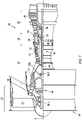
- FIG. 1 schematically illustrates a gas turbine engine 20.
- the gas turbine engine 20 is disclosed herein as a two-spool turbo fan that generally incorporates a fan section 22, a compressor section 24, a combustor section 26 and a turbine section 28.
- the fan section 22 drives air along a bypass flowpath while the compressor section 24 drives air along a core flowpath for compression and communication into the combustor section 26 then expansion through the turbine section 28.
- a turbofan in the disclosed non-limiting embodiment, it should be appreciated that the concepts described herein are not limited to use with turbofans as the teachings may be applied to other types of turbine engine architectures.
- the engine 20 generally includes a low spool 30 and a high spool 32 mounted for rotation about an engine central longitudinal axis A relative to an engine case structure 36 via several bearing compartments 38.
- the low spool 30 generally includes an inner shaft 40 that interconnects a fan 42, a low pressure compressor (“LPC”) 44 and a low pressure turbine (“LPT”) 46.
- the inner shaft 40 drives the fan 42 directly or through a geared architecture 48 to drive the fan 42 at a lower speed than the low spool 30.
- An exemplary reduction transmission is an epicyclic transmission, namely a planetary or star gear system.
- the high spool 32 includes an outer shaft 50 that interconnects a high pressure compressor (“HPC”) 52 and high pressure turbine (“HPT”) 54.
- a combustor 56 is arranged between the high pressure compressor 52 and the high pressure turbine 54.
- the inner shaft 40 and the outer shaft 50 are concentric and rotate about the engine central longitudinal axis A which is collinear with their longitudinal axes.
- Core airflow is compressed by the LPC 44 then the HPC 52, mixed with the fuel and burned in the combustor 56, then expanded over the HPT 54 and the LPT 46.
- the HPT 54 and the LPT 46 rotationally drive the respective high spool 32 and low spool 30 in response to the expansion.
- a system 80 for particulate discrimination includes a controller 82, a control interface 84, a sensor system 86, a database 88, a discrimination module 90, a debris damage module 92, and an engine control module 94.
- the controller 82 may be configured as a central network element or hub with access to various systems and may be implemented in a single processor, one or more processors and/or one or more tangible, non-transitory memories and be capable of implementing logic.
- Each processor can be a general purpose processor, a digital signal processor (DSP), an application specific integrated circuit (ASIC), a field programmable gate array (FPGA) or other programmable logic device, or any combination thereof.
- DSP digital signal processor
- ASIC application specific integrated circuit
- FPGA field programmable gate array
- the controller 82 may include a processor configured to implement various logical operations in response to execution of instructions.
- instructions may be stored on a non-transitory, tangible, computer readable medium configured to communicate with other components.
- the system 80 performs various operations.
- the controller 82 may also be in electronic communication with a user through the control interface 84, for example, a multifunction display.
- the control interface 84 enables a user to interact with the system 80, to issue commands and display information such as warnings.
- the controller 82 may also be in electronic communication with the sensor system 86 that may include, for example, as a particulate sensor, a temperature sensor, a torque sensor, a speed sensor, a pressure sensor, a position sensor, an accelerometer, a mass flow sensor, etc.
- the sensor system 86 may include, for example, as a particulate sensor, a temperature sensor, a torque sensor, a speed sensor, a pressure sensor, a position sensor, an accelerometer, a mass flow sensor, etc.
- the controller 82 may also be in electronic communication with the database 88 to store and maintain data such as sensor data, configuration settings, response models such as the model data 96, and/or the like. Data may be stored or recalled from the database 88 in response to commands from the controller 82.
- the controller 82 may also be in electronic communication with the discrimination module 90.
- the discrimination module 90 may receive sensor data 98 to discriminate between categories of foreign object debris including hard FOD (e.g., fasteners, rocks, etc.) and particulate FOD (e.g., silicate sand, dust, volcanic ash, sea-salt, smoke, steam, water vapor, and/or the like).
- the hard particulate FOD may be anything larger than about 1 mm (0.04 inches).
- Particulate FOD can also be damaging, but is not labeled as "hard" FOD.
- Hard vs soft corresponds to size (hard > 1mm, particulate ⁇ 1mm average particle diameters). Both hard and particulate may be damaging or non-damaging, for example, a large piece of chalk (>>1mm) is considered non-damaging hard FOD.
- the discrimination module 90 discriminates between categories of foreign object debris based on the sensor data 98 and algorithms such as the model data 96 which may define the various categories of hard FOD and particulate FOD within a look-up table or other relationship.
- the discrimination module 90 may determine a quantity, a size, and a type of the FOD including both hard and soft FOD.
- the sensor data 98 may also include GPS data and/or atmospheric data to provide a spacial component to the FOD events.
- the controller 82 may also be in electronic communication with the debris damage module 92.
- the debris damage module 92 may receive outputs from the discrimination module 90 and/or the sensor data 98 and is configured to determine a particulate concentration within the engine 20.
- the debris damage module 92 may determine a quantity or time-based map of ingested particulates between an inlet and an exhaust of the bypass flow-path and/or the core flow-path.
- the debris damage module 92 may determine a hazard level for a given particulate type and/or concentration and may record debris data based on the hazard level, the particulate type, or the particulate concentration.
- the damage module 92 may generate a debris alert or a damage alert via the control interface 84.
- the damage module 92 may calculate accumulated engine damage using a physics-based model of the turbine engine 20.
- the damage model 92 may be implemented separately or may be stored in the database 88.
- the damage model 92 may include modeling of gas turbine engine 20 component erosion based on the particulate type of FOD.
- the damage module 92 may provide the accumulated damage as a percentage of engine life remaining or a time before engine failure and display these measures via the control interface 84.
- the damage module 92 may also generate an alert based on exceeding a threshold value.
- the controller 82 may also be in electronic communication with the engine control module 94.
- the engine control module 94 may be configured to command the engine 20 to, for example, instruct the engine 20 to increase or decrease shaft speeds, fuel flow, vane geometry, alter bypass airflow, set valves, etc.
- the controller 82 may control the turbine engine 20 in response to the damage module 92 and/or discrimination module 90 outputs.
- the engine control module 94 may reduce fuel flow in response to exceeding an engine damage threshold as determined by the damage module 92.
- the sensor system 86 includes a particulate sensor assembly 100 having sensing volumes in areas such as an inlet ingestion sensing region 202 and a turbine gas path sensing region 204.
- a first sensing volume 206 may define the inlet ingestion sensing region 202.
- a second particulate sensor assembly may be arranged to observe a second sensing volume 208 within bypass flow-path proximate the inlet 214 of bypass duct 216.
- a third particulate sensor assembly may be coupled to the compressor section 24 to observe a third sensing volume 210 within core flow-path.
- a fourth particulate sensor assembly may be coupled proximate the exit 218 of bypass duct 216 to observe a fourth sensing volume 212 of the bypass flow-path exhaust and/or the core flow-path exhaust. It will be appreciated that any number of sensing volumes may be defined by a particulate sensor assembly configured for a particular area of interest.
- the sensor assembly 100 operates in the optical realm.
- optical refers to electromagnetic radiation in the wavelength range between 100 nm and 1 mm.
- light and “visible radiation” (VIS) refer to the wavelength range between 400 nm and 800 nm, which can be perceived by the human eye.
- VIS visible radiation
- Optical radiation with wavelengths shorter than 400 nm is called ultraviolet (UV) radiation and is further subdivided in UV-A, UV-B and UV-C ranges.
- IR radiation with wavelengths longer than 800 nm is called infrared radiation (IR) and is similarly divided into IR-A (near-infrared, or NIR), IR-B (short-wavelength infrared, or SWIR), and IR-C (long-wavelength infrared, or LWIR).
- IR-A near-infrared, or NIR
- IR-B short-wavelength infrared, or SWIR
- IR-C long-wavelength infrared, or LWIR.
- the blue LED may emit light between 380 nm and 600 nm and the infrared LED may emit light at a wavelength between 600 nm and 2000 nm.
- the terahertz (THz) regime (e.g., GHz-THz: 50GHz (6mm) - 3THz (0.1mm); THz is typically defined as 0.3-3THz (1mm-0.1mm) facilitates discrimination of hard FOD.
- Materials such as plastic, gasoline, paper, etc. are essentially transparent in the terahertz (THz) regime while metal and carbon fiber, which are typical examples of hard FOD, are reflected, providing a parameter by which to discriminate between damaging and non-damaging FOD.
- the terahertz (THz) regime spectroscopy is also able to obtain spectra for water vapor, polar plastics, etc., to thereby permit enhanced discrimination and identification thereof.
- Operation in the terahertz (THz) regime provides a response to materials in comparison to the UV/VIS/IR optical regime spectroscopy to provide additional parameters for discrimination between damaging and non-damaging FOD.
- Each source can be configured to emit within a specific GHz-THz waveband, or scan across wavebands. Scanning across wavebands enables discrimination via terahertz (THz) spectroscopy or multiple wavebands from different sources also enables terahertz (THz) spectroscopy measurements if wavebands are selected for materials of interest to identify.
- interrogation with GHz-THz wavebands enables the sensor to detect hard FOD in the presence of high concentrations of particulates, such as dust and fog that are transparent in specific GHz-THz wavebands.
- This feature is also useful for providing robustness to contamination on the surface of the sensor, where the GHz-THz radiation, unlike visible-IR radiation, can penetrate through such contaminants such as oil, dirt, and water without significant losses or scattering which would otherwise adversely affect the detection and discrimination of FOD.
- the sensor system 86 may include a coherent Light Detection and Ranging (LIDAR) sensor source.
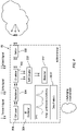
- the sensor system 86 generally includes sensor interface optic system 300, a circulator 302, a modulator 304, an RF oscillator 306 and a continuous wave (CW) laser 308.
- the circulator 302 is a passive, non-reciprocal three or four-port device that only allows a microwave or radio-frequency signal to exit through the port directly after the one it entered.
- the circulator 302 is in communication with a 3dB coupler 310 thence to a detector 312 that is in communication with the damage module 92 and/or discrimination module 90 outputs.
- a "3dB coupler" enables the reference signal and the received signal to be combined before being converted into an electrical signal by the detector 312, however, various coupling schemes may be utilized. Alternativley, the circualtor 302 may be in commiunication directly with the detector 312.
- the sensor interface optic system 300 may include a fiber optic cable 320 with one core 322A ( FIG.5 ) or a multiple of cores 322A, 322B ( FIG 6 ).
- a coupling optic 324 such as a lens may be utilized to increase sensitivity by increasing the collection area, and provide beam shaping to tailor the sensing region.
- the coupling optic 324 may be located in a surface adjacent to a gas turbine engine gas path to provide a smooth flow path.
- a window e.g. composed of sapphire
- the coupling optic 324 can be located remote from the continuous wave (CW) laser 308 with the fiber optic cable 320 therebetween.
- a dual core fiber optic ( FIG. 6 ) may be used for coupling modulated laser light.
- the dual-core fiber optic may be used for coupling the scattered light back to the circulator 302 to mix the transmitted signal with the return signal for processing.
- the dual-core fiber optic may reduce optical noise that may be otherwise caused by scattering of the transmitted signal back to the circulator.
- multi-core bundles of fiber optics may be utilized to provide multiple source locations for triangulation without substantially increasing the sensor footprint.
- Multiple sensing volumes which may be considered as the overlap between light source emission and detector field-of-view of the respective source/detector combinations, provide the sensor with additional information about the type of the particles.
- Multiple detectors positioned to receive light scattered at different scattering angles, which may be considered angle between the light cone's central axis and the central axis of the detector's field of view, interrogate the size of the FOD as the light scattering cross section of the FOD is dependent on both the scattering angle and the size of the FOD and may provide information on the surface roughness of hard FOD. Furthermore, the FOD's light scattering cross section is also dependent on wavelength.
- the signals received from light sources of multiple wavelength provides additional information on the size of the particle, but also may provide information on the surface optical properties, such as reflectance and absorption for discriminating FOD types.
- Particulate FOD is more representative of signals being detected by both overlapping and non-overlapping sensing volumes.
- Hard FOD may only be detected by the non-overlapping sensing volume at a distance from the detector where typically particulate FOD will not be detected as the scattered light is at such low intensity (scattered light from particulate FOD close to the sensor can be detected).
- multiple angles can be used to discriminate particulate types in close proximity to the sensor (assumes particulate FOD is dispersed throughout the inlet), however if hard FOD is close enough to the sensor to pick up the side and forward scatter, that information can be used to provide additional discrimination (surface roughness of hard FOD, absorbance, reflectance).
- a method 400 of foreign object debris discrimination with the detection system 80 is disclosed in terms of functional block diagrams.
- the functions of the logic are programmed software routines capable of execution in various microprocessor based electronics control embodiments and represented herein as the block diagrams. These functions may be enacted in either dedicated hardware circuitry or programmed software routines capable of execution in a microprocessor-based electronics control embodiment.
- a modulated, e.g., amplitude, frequency, etc., coherent light source (Visual; Infrared; Terahertz wavelength range) is emitted (402).
- the modulation frequency needs to be fast enough to correspond with light to be emitted, scattered, and returned.
- the frequency may be linearly dependent with time and takes a time T from f 0 to f max .
- the source has a spatial/temporal coherence from the source to the FOD particle and back.
- the same coherent source is used as a transmit signal to illuminate the FOD particles and as reference, local modulated signal. That is, a majority of the coherent light is transmitted towards the FOD particles to illuminate the FOD particles and a small fraction is used as a reference dependent on the light scatter.
- the reference signal will have the same frequency of the transmitted signal.
- the light scattered from the FOD particles is then collected (404) at the detector 312.
- the reference signal is mixed with the return signal (406).
- the total signal at the detector may be expressed as: I ⁇ I LS + I RS + 2 I LS I RS cos 2 ⁇ f RS ⁇ f LS t where I LS and f LS is the return signal amplitude and frequency, respectively, and I RS and f RS is the mixed reference signal amplitude and frequency, respectively.
- Relative particle distance with respect to detector cannot be obtained for all distances with returned signal and local signal phase difference (( ⁇ RS - ⁇ LS ). Phase difference is an ambiguous metric for large particle distances.
- an amplitude check is performed (408).
- the amplitude check may be utilized to determine if particulate FOD or hard FOD is detected. For example, the amplitude check would identify if a pulse shape from separate sensors is sufficiently narrow and of low amplitude to be considered particulate FOD, while a larger pulse width and amplitude will be indicative of hard FOD. Furthermore, if a low amplitude pulse of sufficiently large pulse width is detected on the backscatter sensor, but not in the forward or side scatter sensors, then the particulate can be considered hard FOD that has been detected at a distance beyond the forward and side scatter sensing volumes.
- the foreign object debris size and type can be based on characterizing the one or more particulates of foreign object debris.
- the sensor data may have different signatures that can be used to distinguish between particulates, smoke, dust, water, and metallic particulates.
- signal strength may vary depending upon the distance of particulate FOD from the optical sensors, the controller can compute ratio values to scale results. Scattering volume ratios can provide information on the type of particulate based on the scattering properties, such as polarization and index of refraction.
- spectral information is capable of providing identification of specific material, e.g. water vapor, in addition to providing sensor robustness to contamination (such as water and oil) on the surface of the detector and ability to detect hard FOD in the presence of high concentration of specific particulate FOD (such as fog and dust).
- the signal phases are not relevant in a modulation scheme.
- the frequency shift is determined (410).
- the frequency difference is proportional to the transmitted signal round trip travel time from the source to FOD particle and back, after being scattered by the FOD particle, to the detector 312. Travel time is proportional to the FOD particle's relative distance to detection system.
- a source frequency is modulated with a triangular function, e.g., the dotted circle in FIG. 8 shows the frequency shift.
- ⁇ f up and ⁇ f down would have the same beat frequency.
- f RS ⁇ f LS ⁇ 0 the frequency of the received signal is shifted in time due to the Doppler shift.
- the difference in traversed paths between the reference signal and the received signal shows for a source frequency modulated with a triangular function.
- ⁇ f up and ⁇ f down are different frequency beats due to the FOD particle's velocity, i.e., the Doppler shift.
- the FOD particle velocity and relative distance with respect to the detection system can be obtained with a triangular modulation quasi-simultaneously, depending on the modulation rate B/T measuring the two beats, ⁇ f up and ⁇ f down .
- the analysis of the frequency beats provides the particle's Vr and R.
- the particle's velocity vector (without assuming laminar flow), and with a minimum of one source and three detectors with different viewing angles surrounding the source are required.
- triangulation can be utilized with multiple sensors to determine the FOD particle's absolute position (and velocity). Triangulation is implemented to determine the velocity components with respect to an engine intake reference system. Analysis of frequency beats of the FOD particle at different points in the beam will increase the velocity and relative position accuracy. Visual; Infrared; Terahertz wavelength range combination, all using the frequency beats technique, provides complementary information to discriminate types of FOD particulates. For example, to determine the position and velocity of FOD particulates and to provide additional parameters (via interrogation using multiple wavelengths and scattering angles) to characterize FOD particulates by size and type.
- the particle classification is not based on frequency but into the amplitude of the mixed signal I LS I RS .
- the particle scattering signal, I LS is amplified by the reference signal, I RS , hence this technique is more sensitive to the type of particle crossing detectors.
- the total signal at one detector may be defined as: I ⁇ I LS + I RS + 2 I LS I RS cos 2 ⁇ f RS ⁇ f LS t
- I LS I RS Analysis of the amplitude of the mixed signal, I LS I RS will yield particle classification.
- I LS I RS has scattering information from the particle: Its scattering regime a ⁇ provides particle characteristic size, a , information. Especially when combined with mixed signals from source/detectors systems at different viewing angles and from different wavelengths, Vis, IR and THz.
- I LS I RS also provides particle electromagnetic absorption characteristics, through particle's complex index of refraction. THz waves particular interaction with materials provides a key differentiator to classify particles. This is enhanced when THz signals are compared to IR or Vis signals of the same particles. Scattering results are compared with tabulated data of hard FOD scattering data to determine with more accuracy the type of particle.
- a velocity correction (412) and a velocity update average (414) may be performed by assuming laminar flow.
- the velocity correction may begin with an initial FOD particle velocity measurement corrected by the angle of coincidence because the velocity measured will be a scalar projection of the FOD velocity.
- the measured velocity must be divided by COS (theta) to obtain the FOD velocity assuming the FOD has a velocity in the direction of the laminar flow field ( FIG. 10 ).
- the measurement process can be iterated as the FOD passes through the entire sensing region, whereby theta will also be changed theta0, theta1, and theta2 (and angles therebetween).
- the velocity may thus be averaged by performing the measurements iteratively, and an updated FOD particle velocity will be output after the FOD particle has completed its trajectory passing entirely through the sensing region.
- independent LIDAR sensors FIG. 11
- independent LIDAR sensors FIG. 11
- deviations between the measured velocities would indicate that the FOD particulate is indeed not following the trajectory of the laminar flow field. The extent of the deviation could then be used to assign a more accurate measurement uncertainty.
- three independent LIDAR sensors located at circumferentially around the inlet may be utilized to provide an absolute velocity without requiring assumption that the FOD particulates follow a laminar flow trajectory as necessary when using only one or two LIDAR sensors.
- the true trajectory is determined via triangulation of the velocity components. Localization in each of these embodiments may require assumptions of the FOD optical properties such as refractive index, size, geometry, etc., based on the received signal intensity.
- FOD velocity is determined (416).
- One FOD particle velocity component (relative to the sensor) is then known via the velocity update average (414) that takes into account the relative position ( FIG. 10 ) to thereby determine the FOD particle position with high spatial and velocity resolution, e.g, with one LIDAR sensor the position of the FOD is constrained to a radius from the sensor ( FIG. 13 ), with two independent LIDAR sensors the position with respect to a particular LIDAR sensor is constrained to positions where the radii (of the two LIDAR sensors; ( FIG. 14 )) intersect, and with three independent LIDAR sensors, the absolute position and velocity of the FOD particle is known with respect to a reference ( FIG. 15 ) such as the engine.
- a reference FIG. 15
- the system determines almost simultaneously the FOD particle velocity and relative position with high spatial resolution with only one detector and one modulated light source.
- the velocity is determined using the Doppler shift technique based on interferometry which results in a high spatial resolution.
- the system is not limited by detector noise (thermal noise) as the mixed signal is that which is detected and dependent on amplitude of reference modulated signal and particle scattering echo.
- the LIDAR sensors are not blinded by external light sources or stray light which do not produce a resulting signal when mixed with modulated reference signal.
- the optical system may be configured to screen out particulate FOD such as water vapor, ice crystals, fog, smoke, dust, or ash in response to the chosen GHz-THz waveband that is transmissive with respect to the particulate FOD to be screened out.
- the particulate FOD may also be a marine aerosol, or salt particulates, such as water or oil droplets surrounding NaCl particulates which may be considered damaging FOD.
Landscapes
- Physics & Mathematics (AREA)
- Engineering & Computer Science (AREA)
- General Physics & Mathematics (AREA)
- Electromagnetism (AREA)
- Remote Sensing (AREA)
- Radar, Positioning & Navigation (AREA)
- Computer Networks & Wireless Communication (AREA)
- Chemical & Material Sciences (AREA)
- Life Sciences & Earth Sciences (AREA)
- Immunology (AREA)
- Pathology (AREA)
- General Health & Medical Sciences (AREA)
- Biochemistry (AREA)
- Analytical Chemistry (AREA)
- Health & Medical Sciences (AREA)
- Dispersion Chemistry (AREA)
- Optics & Photonics (AREA)
- Investigating Or Analysing Materials By Optical Means (AREA)
Abstract
Description
- The present disclosure (invention) relates to foreign object debris discrimination.
- Aircraft engines can be damaged by Foreign Object Debris (FOD). Large objects can cause significant changes detected by engine monitoring systems, such as shaft vibration measurement. Smaller objects however, such as sand grains, can cause damage that is barely visible but may still damage or weaken components.
- Various optical particulate ingestion sensor systems are being integrated into gas turbine engines to identify FOD. Various multi-wavelength, multi-angle scattering light sources (e.g., LED) and sensors (e.g., photodiodes) provide scattering cross sections, however, this may not be suitable for FOD which can have complex geometries and may be composed of multiple materials. Further, due to the reflective and transient nature of particulate FOD such as moisture, fog, dust, ash, or smoke, the visibility conditions of the FOD may be effected.
- A method of foreign object debris discrimination according to an aspect of the present invention includes illuminating a particle located within a sensing volume with a modulated electromagnetic radiation pulse emitted from a source; receiving one or more electromagnetic radiation return signals that have been scattered by the particle illuminated by the modulated electromagnetic radiation pulse at a detector; mixing, using a controller, the electromagnetic radiation return signal of amplitude IRS and frequency with a reference signal of amplitude and frequency; analyzing, using the controller, an amplitude of the mixed signal, and frequency of the mixed signal; and classifying, using the controller, a particle position, a velocity, and electromagnetic characteristic of the particle based on the amplitude, and frequency, of the mixed signal.
- Optionally, the reference signal with amplitude ILS and frequency fLS is amplified by the return signal with amplitude IRS and frequency fRS .
- Optionally, analyzing, using the controller, the amplitude of the mixed signal


- Optionally, analyzing, using the controller, the amplitude of the mixed signal comprises signals from different viewing angles.
- Optionally, analyzing, using the controller, the amplitude of the mixed signal comprises signals from different wavelengths.
- Optionally, the electromagnetic characteristic further comprises the particle's complex index of refraction.
- Optionally, the modulated electromagnetic radiation pulse emitted from the source is used as both to transmit a signal to illuminate particles and as a reference to provide a local modulated signal.
- Optionally, the modulated electromagnetic radiation pulse emitted from the source is emitted as a single frequency.
- Optionally, the present invention further comprises determining a velocity of the particle using the particle's Doppler shift from the frequency of the mixed signal fRS - fLS.
- Optionally, the particle velocity is determined almost simultaneously with a relative position of the particle.
- Optionally, the present invention further comprises determining a velocity of the particle and a relative distance with respect to the source quasi-simultaneously with a triangular modulation depending on the modulation rate B/T measuring the two beats Δfup and Δfdown where the source emits at a frequency within a modulation bandwidth B = fmax - f0.
- A system for particulate discrimination according to an aspect of the present invention includes a continuous wave (CW) laser; a modulator downstream of the continuous wave (CW) laser; a circulator downstream of the modulator; a detector in communication with the circulator; a controller; and a tangible, non-transitory memory configured to communicate with the controller, the tangible, non-transitory memory having instructions stored thereon that, in response to execution by the controller, perform operations comprising: analyzing a frequency beats of a particle at different points in a modulated electromagnetic radiation pulse from the continuous wave (CW) laser to provide a particle velocity and a relative position of the particle.
- Optionally, the modulated electromagnetic radiation pulse is a visual signal.
- Optionally, the modulated electromagnetic radiation pulse is an infrared signal.
- Optionally, the modulated electromagnetic radiation pulse is a terahertz signal.
- Optionally, the present invention further comprises a sensor interface optic system downstream of the circulator.
- Optionally, the sensor interface optic system comprises a coupling optic in a surface of a gas turbine engine.
- Optionally, the present invention further comprises a fiber optic in optical communication with the sensor interface optic system.
- Optionally, the fiber optic comprises a single core.
- Optionally, the fiber optic includes a multiple of cores for coupling scattered light back to the circulator to mix the transmitted modulated electromagnetic radiation pulse with a return signal for processing.
- The foregoing features and elements may be combined in various combinations without exclusivity, unless expressly indicated otherwise. These features and elements as well as the operation thereof will become more apparent in light of the following description and the accompanying drawings. It should be appreciated that the following description and drawings are intended to be exemplary in nature and non-limiting.
- Various features will become apparent to those skilled in the art from the following detailed description of the disclosed non-limiting embodiment. The drawings that accompany the detailed description can be briefly described as follows:
-
FIG. 1 is a schematic cross-section of a gas turbine engine. -
FIG. 2 is a perspective view of a system for particulate discrimination. -
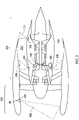
FIG. 3 is sectional view of a nacelle assembly for the gas turbine engine with the foreign object detection system. -
FIG. 4 is a schematic view of a particulate sensor system. -
FIG. 5 is a schematic view of a fiber optic light coupling according to one disclosed non-limiting embodiment. -
FIG. 6 is a schematic view of a fiber optic light coupling according to another disclosed non-limiting embodiment. -
FIG. 7 is a block diagram illustrating operation of the foreign object detection system according to one non-limiting embodiment. -
FIG. 8 is a graphical representation of a source frequency modulated with a triangular function for a stationary particle, the dotted circle shows the frequency shift. -
FIG. 9 is a graphical representation of a source frequency modulated with a triangular function for a moving particle.. -
FIG. 10 is schematic view of a LIDAR sensor embodiment according to another disclosed non-limiting embodiment. -
FIG. 11 is schematic view of a LIDAR sensor embodiment according to another disclosed non-limiting embodiment. -
FIG. 12 is schematic view of a LIDAR sensor embodiment according to another disclosed non-limiting embodiment. -
FIG. 13 is schematic view of theFIG. 10 LIDAR sensor embodiment that provides relative position and velocity (requires laminar flow assumption for absolute velocity). -
FIG. 14 is schematic view of theFIG. 11 LIDAR sensor embodiment that provides relative position and velocity (requires laminar flow assumption for absolute velocity, but provides indication as to if the FOD is not following a laminar flow trajectory). -
FIG. 15 is schematic view of theFIG. 12 LIDAR sensor embodiment that provides provides absolute position and velocity (without requiring laminar flow assumption). -
FIG. 1 schematically illustrates agas turbine engine 20. Thegas turbine engine 20 is disclosed herein as a two-spool turbo fan that generally incorporates afan section 22, acompressor section 24, acombustor section 26 and aturbine section 28. Thefan section 22 drives air along a bypass flowpath while thecompressor section 24 drives air along a core flowpath for compression and communication into thecombustor section 26 then expansion through theturbine section 28. Although depicted as a turbofan in the disclosed non-limiting embodiment, it should be appreciated that the concepts described herein are not limited to use with turbofans as the teachings may be applied to other types of turbine engine architectures. - The
engine 20 generally includes alow spool 30 and ahigh spool 32 mounted for rotation about an engine central longitudinal axis A relative to anengine case structure 36 viaseveral bearing compartments 38. Thelow spool 30 generally includes aninner shaft 40 that interconnects afan 42, a low pressure compressor ("LPC") 44 and a low pressure turbine ("LPT") 46. Theinner shaft 40 drives thefan 42 directly or through a gearedarchitecture 48 to drive thefan 42 at a lower speed than thelow spool 30. An exemplary reduction transmission is an epicyclic transmission, namely a planetary or star gear system. - The
high spool 32 includes anouter shaft 50 that interconnects a high pressure compressor ("HPC") 52 and high pressure turbine ("HPT") 54. Acombustor 56 is arranged between thehigh pressure compressor 52 and thehigh pressure turbine 54. Theinner shaft 40 and theouter shaft 50 are concentric and rotate about the engine central longitudinal axis A which is collinear with their longitudinal axes. - Core airflow is compressed by the
LPC 44 then the HPC 52, mixed with the fuel and burned in thecombustor 56, then expanded over the HPT 54 and theLPT 46. The HPT 54 and theLPT 46 rotationally drive the respectivehigh spool 32 andlow spool 30 in response to the expansion. - With reference to
FIG. 2 , asystem 80 for particulate discrimination includes acontroller 82, acontrol interface 84, asensor system 86, adatabase 88, adiscrimination module 90, adebris damage module 92, and anengine control module 94. Thecontroller 82 may be configured as a central network element or hub with access to various systems and may be implemented in a single processor, one or more processors and/or one or more tangible, non-transitory memories and be capable of implementing logic. Each processor can be a general purpose processor, a digital signal processor (DSP), an application specific integrated circuit (ASIC), a field programmable gate array (FPGA) or other programmable logic device, or any combination thereof. Thecontroller 82 may include a processor configured to implement various logical operations in response to execution of instructions. For example, instructions may be stored on a non-transitory, tangible, computer readable medium configured to communicate with other components. In response to execution by the controller, thesystem 80 performs various operations. - The
controller 82 may also be in electronic communication with a user through thecontrol interface 84, for example, a multifunction display. Thecontrol interface 84 enables a user to interact with thesystem 80, to issue commands and display information such as warnings. - The
controller 82 may also be in electronic communication with thesensor system 86 that may include, for example, as a particulate sensor, a temperature sensor, a torque sensor, a speed sensor, a pressure sensor, a position sensor, an accelerometer, a mass flow sensor, etc. - The
controller 82 may also be in electronic communication with thedatabase 88 to store and maintain data such as sensor data, configuration settings, response models such as themodel data 96, and/or the like. Data may be stored or recalled from thedatabase 88 in response to commands from thecontroller 82. - The
controller 82 may also be in electronic communication with thediscrimination module 90. Thediscrimination module 90 may receivesensor data 98 to discriminate between categories of foreign object debris including hard FOD (e.g., fasteners, rocks, etc.) and particulate FOD (e.g., silicate sand, dust, volcanic ash, sea-salt, smoke, steam, water vapor, and/or the like). In one example, the hard particulate FOD may be anything larger than about 1 mm (0.04 inches). Particulate FOD can also be damaging, but is not labeled as "hard" FOD. Hard vs soft corresponds to size (hard > 1mm, particulate <1mm average particle diameters). Both hard and particulate may be damaging or non-damaging, for example, a large piece of chalk (>>1mm) is considered non-damaging hard FOD. - The
discrimination module 90 discriminates between categories of foreign object debris based on thesensor data 98 and algorithms such as themodel data 96 which may define the various categories of hard FOD and particulate FOD within a look-up table or other relationship. Thediscrimination module 90 may determine a quantity, a size, and a type of the FOD including both hard and soft FOD. In various embodiments, thesensor data 98 may also include GPS data and/or atmospheric data to provide a spacial component to the FOD events. - The
controller 82 may also be in electronic communication with thedebris damage module 92. Thedebris damage module 92 may receive outputs from thediscrimination module 90 and/or thesensor data 98 and is configured to determine a particulate concentration within theengine 20. Thedebris damage module 92 may determine a quantity or time-based map of ingested particulates between an inlet and an exhaust of the bypass flow-path and/or the core flow-path. Thedebris damage module 92 may determine a hazard level for a given particulate type and/or concentration and may record debris data based on the hazard level, the particulate type, or the particulate concentration. In various embodiments, thedamage module 92 may generate a debris alert or a damage alert via thecontrol interface 84. - The
damage module 92 may calculate accumulated engine damage using a physics-based model of theturbine engine 20. Thedamage model 92 may be implemented separately or may be stored in thedatabase 88. Thedamage model 92 may include modeling ofgas turbine engine 20 component erosion based on the particulate type of FOD. Thedamage module 92 may provide the accumulated damage as a percentage of engine life remaining or a time before engine failure and display these measures via thecontrol interface 84. Thedamage module 92 may also generate an alert based on exceeding a threshold value. - The
controller 82 may also be in electronic communication with theengine control module 94. Theengine control module 94 may be configured to command theengine 20 to, for example, instruct theengine 20 to increase or decrease shaft speeds, fuel flow, vane geometry, alter bypass airflow, set valves, etc. In various embodiments, thecontroller 82 may control theturbine engine 20 in response to thedamage module 92 and/ordiscrimination module 90 outputs. For example, theengine control module 94 may reduce fuel flow in response to exceeding an engine damage threshold as determined by thedamage module 92. - With reference to
FIG. 3 , in various embodiments, thesensor system 86 includes aparticulate sensor assembly 100 having sensing volumes in areas such as an inletingestion sensing region 202 and a turbine gaspath sensing region 204. Afirst sensing volume 206 may define the inletingestion sensing region 202. A second particulate sensor assembly may be arranged to observe asecond sensing volume 208 within bypass flow-path proximate the inlet 214 ofbypass duct 216. A third particulate sensor assembly may be coupled to thecompressor section 24 to observe athird sensing volume 210 within core flow-path. A fourth particulate sensor assembly may be coupled proximate theexit 218 ofbypass duct 216 to observe afourth sensing volume 212 of the bypass flow-path exhaust and/or the core flow-path exhaust. It will be appreciated that any number of sensing volumes may be defined by a particulate sensor assembly configured for a particular area of interest. - In one embodiment, the
sensor assembly 100 operates in the optical realm. The term "optical" as utilized herein refers to electromagnetic radiation in the wavelength range between 100 nm and 1 mm. The terms "light" and "visible radiation" (VIS) refer to the wavelength range between 400 nm and 800 nm, which can be perceived by the human eye. Optical radiation with wavelengths shorter than 400 nm is called ultraviolet (UV) radiation and is further subdivided in UV-A, UV-B and UV-C ranges. Optical radiation with wavelengths longer than 800 nm is called infrared radiation (IR) and is similarly divided into IR-A (near-infrared, or NIR), IR-B (short-wavelength infrared, or SWIR), and IR-C (long-wavelength infrared, or LWIR). In this embodiment, the blue LED may emit light between 380 nm and 600 nm and the infrared LED may emit light at a wavelength between 600 nm and 2000 nm. The terahertz (THz) regime (e.g., GHz-THz: 50GHz (6mm) - 3THz (0.1mm); THz is typically defined as 0.3-3THz (1mm-0.1mm) facilitates discrimination of hard FOD. Materials such as plastic, gasoline, paper, etc. are essentially transparent in the terahertz (THz) regime while metal and carbon fiber, which are typical examples of hard FOD, are reflected, providing a parameter by which to discriminate between damaging and non-damaging FOD. The terahertz (THz) regime spectroscopy is also able to obtain spectra for water vapor, polar plastics, etc., to thereby permit enhanced discrimination and identification thereof. Operation in the terahertz (THz) regime provides a response to materials in comparison to the UV/VIS/IR optical regime spectroscopy to provide additional parameters for discrimination between damaging and non-damaging FOD. Each source can be configured to emit within a specific GHz-THz waveband, or scan across wavebands. Scanning across wavebands enables discrimination via terahertz (THz) spectroscopy or multiple wavebands from different sources also enables terahertz (THz) spectroscopy measurements if wavebands are selected for materials of interest to identify. In addition to providing discrimination and identification of FOD, interrogation with GHz-THz wavebands enables the sensor to detect hard FOD in the presence of high concentrations of particulates, such as dust and fog that are transparent in specific GHz-THz wavebands. This feature is also useful for providing robustness to contamination on the surface of the sensor, where the GHz-THz radiation, unlike visible-IR radiation, can penetrate through such contaminants such as oil, dirt, and water without significant losses or scattering which would otherwise adversely affect the detection and discrimination of FOD. - With reference to
FIG. 4 , in one illustrated embodiment, thesensor system 86 may include a coherent Light Detection and Ranging (LIDAR) sensor source. Thesensor system 86 generally includes sensorinterface optic system 300, acirculator 302, amodulator 304, anRF oscillator 306 and a continuous wave (CW)laser 308. Thecirculator 302 is a passive, non-reciprocal three or four-port device that only allows a microwave or radio-frequency signal to exit through the port directly after the one it entered. Thecirculator 302 is in communication with a3dB coupler 310 thence to adetector 312 that is in communication with thedamage module 92 and/ordiscrimination module 90 outputs. A "3dB coupler" enables the reference signal and the received signal to be combined before being converted into an electrical signal by thedetector 312, however, various coupling schemes may be utilized. Alternativley, thecircualtor 302 may be in commiunication directly with thedetector 312. - The sensor
interface optic system 300 may include afiber optic cable 320 with onecore 322A (FIG.5 ) or a multiple ofcores FIG 6 ). Acoupling optic 324 such as a lens may be utilized to increase sensitivity by increasing the collection area, and provide beam shaping to tailor the sensing region. Thecoupling optic 324 may be located in a surface adjacent to a gas turbine engine gas path to provide a smooth flow path. A window (e.g. composed of sapphire) may also be utilized in addition to or in place of the coupling optic to provide robustness to the sensor where the window may be located in a surface adjacent to a gas turbine engine gas path to provide a smooth flow path. That is, thecoupling optic 324 can be located remote from the continuous wave (CW)laser 308 with thefiber optic cable 320 therebetween. - A dual core fiber optic (
FIG. 6 ) may be used for coupling modulated laser light. The dual-core fiber optic may be used for coupling the scattered light back to thecirculator 302 to mix the transmitted signal with the return signal for processing. The dual-core fiber optic may reduce optical noise that may be otherwise caused by scattering of the transmitted signal back to the circulator. Alternatively, multi-core bundles of fiber optics may be utilized to provide multiple source locations for triangulation without substantially increasing the sensor footprint. - Multiple sensing volumes which may be considered as the overlap between light source emission and detector field-of-view of the respective source/detector combinations, provide the sensor with additional information about the type of the particles. Multiple detectors positioned to receive light scattered at different scattering angles, which may be considered angle between the light cone's central axis and the central axis of the detector's field of view, interrogate the size of the FOD as the light scattering cross section of the FOD is dependent on both the scattering angle and the size of the FOD and may provide information on the surface roughness of hard FOD. Furthermore, the FOD's light scattering cross section is also dependent on wavelength. Thus, the signals received from light sources of multiple wavelength provides additional information on the size of the particle, but also may provide information on the surface optical properties, such as reflectance and absorption for discriminating FOD types.
- Particulate FOD is more representative of signals being detected by both overlapping and non-overlapping sensing volumes. Hard FOD may only be detected by the non-overlapping sensing volume at a distance from the detector where typically particulate FOD will not be detected as the scattered light is at such low intensity (scattered light from particulate FOD close to the sensor can be detected). As demonstrated for smoke detection applications, multiple angles can be used to discriminate particulate types in close proximity to the sensor (assumes particulate FOD is dispersed throughout the inlet), however if hard FOD is close enough to the sensor to pick up the side and forward scatter, that information can be used to provide additional discrimination (surface roughness of hard FOD, absorbance, reflectance).
- With reference to
FIG. 7 , amethod 400 of foreign object debris discrimination with thedetection system 80 is disclosed in terms of functional block diagrams. The functions of the logic are programmed software routines capable of execution in various microprocessor based electronics control embodiments and represented herein as the block diagrams. These functions may be enacted in either dedicated hardware circuitry or programmed software routines capable of execution in a microprocessor-based electronics control embodiment. - Initially, a modulated, e.g., amplitude, frequency, etc., coherent light source (Visual; Infrared; Terahertz wavelength range) is emitted (402). The source emits at a frequency within a modulation bandwidth:

- The modulation frequency needs to be fast enough to correspond with light to be emitted, scattered, and returned. For example, the precision on the velocity can be determined by


- The light scattered from the FOD particles is then collected (404) at the
detector 312. Next, the reference signal is mixed with the return signal (406). The total signal at the detector may be expressed as:
- If a FOD particle is stationary with respect to the non-modulated light source, the frequency of the return, fRS , and the reference signal fLS , frequency are the same. Particle velocity can be found if the particle is moving with respect to a non-modulated light source, fRS - fLS ≠ 0 due to the Doppler effect.

- Relative particle distance with respect to detector cannot be obtained for all distances with returned signal and local signal phase difference ((ϕRS - ϕLS ). Phase difference is an ambiguous metric for large particle distances.
- Next, an amplitude check is performed (408). The amplitude check may be utilized to determine if particulate FOD or hard FOD is detected. For example, the amplitude check would identify if a pulse shape from separate sensors is sufficiently narrow and of low amplitude to be considered particulate FOD, while a larger pulse width and amplitude will be indicative of hard FOD. Furthermore, if a low amplitude pulse of sufficiently large pulse width is detected on the backscatter sensor, but not in the forward or side scatter sensors, then the particulate can be considered hard FOD that has been detected at a distance beyond the forward and side scatter sensing volumes. The foreign object debris size and type can be based on characterizing the one or more particulates of foreign object debris. For example, through testing and calibration, the sensor data may have different signatures that can be used to distinguish between particulates, smoke, dust, water, and metallic particulates. Since signal strength may vary depending upon the distance of particulate FOD from the optical sensors, the controller can compute ratio values to scale results. Scattering volume ratios can provide information on the type of particulate based on the scattering properties, such as polarization and index of refraction.
- Recognition of the resultant FOD type facilitates determination of maintenance requirements such that scheduling thereof may be reduced. The ability of wavelength range within a terahertz (THz) regime to have a different optical response to materials in comparison to the optical (UV/VIS/IR) regime provides additional parameters for discrimination of damaging and non-damaging FOD. Also, spectral information is capable of providing identification of specific material, e.g. water vapor, in addition to providing sensor robustness to contamination (such as water and oil) on the surface of the detector and ability to detect hard FOD in the presence of high concentration of specific particulate FOD (such as fog and dust).
- The signal phases are not relevant in a modulation scheme. Next, the frequency shift is determined (410).
- If the particle is stationary with respect to the detection system:

- The frequency difference is proportional to the transmitted signal round trip travel time from the source to FOD particle and back, after being scattered by the FOD particle, to the
detector 312. Travel time is proportional to the FOD particle's relative distance to detection system. - A source frequency is modulated with a triangular function, e.g., the dotted circle in
FIG. 8 shows the frequency shift. Δfup and Δfdown would have the same beat frequency. - If the particle is moving with respect to the detection system,

FIG. 9 ) shows for a source frequency modulated with a triangular function. - Δfup and Δfdown are different frequency beats due to the FOD particle's velocity, i.e., the Doppler shift.
- The FOD particle velocity and relative distance with respect to the detection system can be obtained with a triangular modulation quasi-simultaneously, depending on the modulation rate B/T measuring the two beats, Δfup and Δfdown .
- The FOD particle relative position, R, with respect to the detection system is:

- The FOD particle's velocity, Vr, with respect to the detection system is:

- This is assuming that

- The analysis of the frequency beats provides the particle's Vr and R. The particle's velocity vector (without assuming laminar flow), and with a minimum of one source and three detectors with different viewing angles surrounding the source are required.
- Since the distance (and velocity) from the sensor to the FOD particle can only be determined along the vector from the sensor to the FOD particle, triangulation can be utilized with multiple sensors to determine the FOD particle's absolute position (and velocity). Triangulation is implemented to determine the velocity components with respect to an engine intake reference system. Analysis of frequency beats of the FOD particle at different points in the beam will increase the velocity and relative position accuracy. Visual; Infrared; Terahertz wavelength range combination, all using the frequency beats technique, provides complementary information to discriminate types of FOD particulates. For example, to determine the position and velocity of FOD particulates and to provide additional parameters (via interrogation using multiple wavelengths and scattering angles) to characterize FOD particulates by size and type.
- The particle classification is not based on frequency but into the amplitude of the mixed signal

- The total signal at one detector may be defined as:

- Analysis of the amplitude of the mixed signal,


- ILSIRS also provides particle electromagnetic absorption characteristics, through particle's complex index of refraction. THz waves particular interaction with materials provides a key differentiator to classify particles. This is enhanced when THz signals are compared to IR or Vis signals of the same particles. Scattering results are compared with tabulated data of hard FOD scattering data to determine with more accuracy the type of particle.
- Optionally, a velocity correction (412) and a velocity update average (414) may be performed by assuming laminar flow. The velocity correction may begin with an initial FOD particle velocity measurement corrected by the angle of coincidence because the velocity measured will be a scalar projection of the FOD velocity. Thus, the measured velocity must be divided by COS (theta) to obtain the FOD velocity assuming the FOD has a velocity in the direction of the laminar flow field (
FIG. 10 ). To achieve a high degree of certainty on the velocity, the measurement process can be iterated as the FOD passes through the entire sensing region, whereby theta will also be changed theta0, theta1, and theta2 (and angles therebetween). The velocity may thus be averaged by performing the measurements iteratively, and an updated FOD particle velocity will be output after the FOD particle has completed its trajectory passing entirely through the sensing region. - Alternatively, independent LIDAR sensors (
FIG. 11 ) that are angled relative to one another may be utilized to provide additional measurements in different direction to determine to what extent the FOD is deviating from the laminar flow trajectory to provide robustness to velocity measurement. When two independently located LIDAR sensors are utilized, both should confirm measurement of a velocity within the uncertainty of the measurement for a given FOD event that is traveling axially through the inlet, following the trajectory of the laminar flow field and confirming the FOD is traveling with the laminar flow. With two independent LIDAR sensors, deviations between the measured velocities would indicate that the FOD particulate is indeed not following the trajectory of the laminar flow field. The extent of the deviation could then be used to assign a more accurate measurement uncertainty. - Alternatively, three independent LIDAR sensors (
FIG. 12 ) located at circumferentially around the inlet may be utilized to provide an absolute velocity without requiring assumption that the FOD particulates follow a laminar flow trajectory as necessary when using only one or two LIDAR sensors. The true trajectory is determined via triangulation of the velocity components. Localization in each of these embodiments may require assumptions of the FOD optical properties such as refractive index, size, geometry, etc., based on the received signal intensity. - Finally, FOD velocity is determined (416). One FOD particle velocity component (relative to the sensor) is then known via the velocity update average (414) that takes into account the relative position (
FIG. 10 ) to thereby determine the FOD particle position with high spatial and velocity resolution, e.g, with one LIDAR sensor the position of the FOD is constrained to a radius from the sensor (FIG. 13 ), with two independent LIDAR sensors the position with respect to a particular LIDAR sensor is constrained to positions where the radii (of the two LIDAR sensors; (FIG. 14 )) intersect, and with three independent LIDAR sensors, the absolute position and velocity of the FOD particle is known with respect to a reference (FIG. 15 ) such as the engine. - The system determines almost simultaneously the FOD particle velocity and relative position with high spatial resolution with only one detector and one modulated light source. The velocity is determined using the Doppler shift technique based on interferometry which results in a high spatial resolution. The system is not limited by detector noise (thermal noise) as the mixed signal is that which is detected and dependent on amplitude of reference modulated signal and particle scattering echo.
- The LIDAR sensors are not blinded by external light sources or stray light which do not produce a resulting signal when mixed with modulated reference signal. The optical system may be configured to screen out particulate FOD such as water vapor, ice crystals, fog, smoke, dust, or ash in response to the chosen GHz-THz waveband that is transmissive with respect to the particulate FOD to be screened out. The particulate FOD may also be a marine aerosol, or salt particulates, such as water or oil droplets surrounding NaCl particulates which may be considered damaging FOD.
- Although particular step sequences are shown, described, and claimed, it should be appreciated that steps may be performed in any order, separated or combined unless otherwise indicated and will still benefit from the present disclosure.
- The foregoing description is exemplary rather than defined by the limitations within. Various non-limiting embodiments are disclosed herein, however, one of ordinary skill in the art would recognize that various modifications and variations in light of the above teachings will fall within the scope of the appended claims. It is therefore to be appreciated that within the scope of the appended claims, the disclosure may be practiced other than as specifically described. For that reason the appended claims should be studied to determine true scope and content.
Claims (15)
- A method of foreign object debris discrimination, comprising:illuminating a particle located within a sensing volume (206,208,210,212) with a modulated electromagnetic radiation pulse (402) emitted from a source;receiving one or more electromagnetic radiation return signals that have been scattered by the particle illuminated by the modulated electromagnetic radiation pulse (402) at a detector (312);mixing (406), using a controller (82), the electromagnetic radiation return signal of an amplitude and a frequency with a reference signal of an amplitude and a frequency;analyzing, using the controller (82), an amplitude of the mixed signal (406) and frequency of the mixed signal; andclassifying, using the controller (82), a particle position, a velocity, and an electromagnetic characteristic of the particle based on the amplitude and frequency of the mixed signal (406).
- The method as recited in claim 1, wherein the reference signal with the amplitude ILS and the frequency fLS is amplified by the return signal (404) with the amplitude IRS and the frequency fRS ,
- The method as recited in claims 1 or 2, wherein analyzing, using the controller (82), the amplitude of the mixed signal
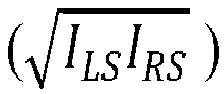

- The method as recited in claims 1 to 3, wherein analyzing, using the controller (82), the amplitude of the mixed signal (406) comprises signals from different viewing angles and/or different wavelengths.
- The method as recited in any preceding claim, wherein the electromagnetic characteristic further comprises the particle's complex index of refraction.
- The method as recited in any preceding claim, wherein the modulated electromagnetic radiation pulse (402) emitted from the source is used as both to transmit a signal to illuminate particles and as a reference to provide a local modulated signal.
- The method as recited in any preceding claim, wherein the modulated electromagnetic radiation pulse (402) emitted from the source is emitted as a single frequency.
- The method as recited in any preceding claim, further comprising determining a velocity of the particle using the particle's Doppler shift from the frequency of the mixed signal ( f RS -fLS ) (406).
- The method as recited in any preceding claim, wherein the particle velocity is determined almost simultaneously with a relative position of the particle.
- The method as recited in any preceding claim, further comprising determining a velocity of the particle and a relative distance with respect to the source quasi-simultaneously with a triangular modulation depending on the modulation rate B/T measuring the two beats (Δfup and Δfdown ) where the source emits at a frequency within a modulation bandwidth (B = fmax - f0 ).
- A system for particulate discrimination, comprising:a continuous wave (CW) laser (308);a modulator (304) downstream of the continuous wave (CW) laser (308);a circulator downstream of the modulator (304);a detector in communication with the circulator (302);a controller (82); anda tangible, non-transitory memory configured to communicate with the controller, the tangible, non-transitory memory having instructions stored thereon that, in response to execution by the controller (82), perform operations comprising:
analyzing a frequency beats of a particle at different points in a modulated electromagnetic radiation pulse (402) from the continuous wave (CW) laser (308) to provide a particle velocity and a relative position of the particle. - The system as recited in claim 11, wherein the modulated electromagnetic radiation pulse is one or more of:a visual signal;an infrared signal;a terahertz signal.
- The system as recited in claims 11 or 12, further comprising a sensor interface optic system (100;300) downstream of the circulator (302).
- The system as recited in claim 13, wherein the sensor interface optic system (100;300) comprises a coupling optic in a surface of a gas turbine engine.
- The system as recited in claim 14, further comprising a fiber optic (320) in optical communication with the sensor interface optic system (100;300), wherein the fiber optic (320) optionally comprises:a single core (320A); ora multiple of cores (322A,322B) for coupling scattered light back to the circulator (302) to mix (406) the transmitted modulated electromagnetic radiation pulse (402) with a return signal (404) for processing.
Applications Claiming Priority (1)
| Application Number | Priority Date | Filing Date | Title |
|---|---|---|---|
| US17/383,781 US12019028B2 (en) | 2021-07-23 | 2021-07-23 | Foreign object debris discrimination with modulated laser light |
Publications (1)
| Publication Number | Publication Date |
|---|---|
| EP4123339A1 true EP4123339A1 (en) | 2023-01-25 |
Family
ID=82701890
Family Applications (1)
| Application Number | Title | Priority Date | Filing Date |
|---|---|---|---|
| EP22186549.6A Pending EP4123339A1 (en) | 2021-07-23 | 2022-07-22 | Foreign object debris discrimination with modulated laser light |
Country Status (2)
| Country | Link |
|---|---|
| US (2) | US12019028B2 (en) |
| EP (1) | EP4123339A1 (en) |
Families Citing this family (1)
| Publication number | Priority date | Publication date | Assignee | Title |
|---|---|---|---|---|
| US12391393B2 (en) | 2023-07-20 | 2025-08-19 | Rtx Corporation | Aircraft propulsion system with inlet air monitoring system and method |
Citations (3)
| Publication number | Priority date | Publication date | Assignee | Title |
|---|---|---|---|---|
| EP2212717A2 (en) * | 2007-10-09 | 2010-08-04 | Danmarks Tekniske Universitet | Coherent lidar system based on a semiconductor laser and amplifier |
| US20120286098A1 (en) * | 2009-11-25 | 2012-11-15 | Poulos Air & Space | Stabilization of unstable space debris |
| US20210025977A1 (en) * | 2019-07-26 | 2021-01-28 | The Aerospace Corporation | Object detection and characterization using a lidar-based sensor |
Family Cites Families (15)
| Publication number | Priority date | Publication date | Assignee | Title |
|---|---|---|---|---|
| US5164784A (en) * | 1992-01-17 | 1992-11-17 | The Boeing Company | CW doppler lidar |
| US5943130A (en) * | 1996-10-21 | 1999-08-24 | Insitec, Inc. | In situ sensor for near wafer particle monitoring in semiconductor device manufacturing equipment |
| US6297878B1 (en) * | 1998-11-13 | 2001-10-02 | Rosemount Aerospace Inc. | Non-scanning, three-axis, self-referenced heterodyne laser air data sensing system |
| US6597446B2 (en) * | 2001-03-22 | 2003-07-22 | Sentec Corporation | Holographic scatterometer for detection and analysis of wafer surface deposits |
| US8372183B2 (en) | 2007-06-12 | 2013-02-12 | Orono Spectral Solution, Inc. | Detection system for airborne particles |
| JP5568322B2 (en) | 2009-03-25 | 2014-08-06 | 日本碍子株式会社 | Particulate matter accumulation detection device |
| US9267919B1 (en) | 2010-05-06 | 2016-02-23 | The Florida International University Board Of Trustees | Nanotip sensor |
| US10598769B2 (en) * | 2013-05-06 | 2020-03-24 | Danmarks Tekniske Universitet | Coaxial direct-detection LIDAR-system |
| US10436904B2 (en) * | 2015-04-15 | 2019-10-08 | The Boeing Company | Systems and methods for modular LADAR scanning |
| US10871452B2 (en) | 2016-06-15 | 2020-12-22 | Kidde Technologies, Inc. | Systems and methods for chamberless smoke detection and indoor air quality monitoring |
| US10845294B1 (en) | 2019-07-03 | 2020-11-24 | Raytheon Technologies Corporation | Systems and methods for particulate ingestion sensing in gas turbine engines |
| US11492967B2 (en) | 2019-07-03 | 2022-11-08 | Raytheon Technologies Corporation | Particulate ingestion sensor for gas turbine engines |
| KR102443656B1 (en) * | 2020-03-30 | 2022-09-16 | 한국과학기술원 | Silicon-OPA-Based LiDAR for Measuring Distance Using Quasi-Frequency Modulation |
| US11726035B2 (en) | 2020-12-11 | 2023-08-15 | Raytheon Technologies Corporation | Terahertz enhanced foreign object debris discrimination for optical particulate sensor |
| US11762086B2 (en) * | 2021-03-02 | 2023-09-19 | GM Global Technology Operations LLC | Generating a high frequency FMCW radar from low frequency FMCW radar |
-
2021
- 2021-07-23 US US17/383,781 patent/US12019028B2/en active Active
-
2022
- 2022-07-22 EP EP22186549.6A patent/EP4123339A1/en active Pending
-
2024
- 2024-05-20 US US18/668,764 patent/US12313562B2/en active Active
Patent Citations (3)
| Publication number | Priority date | Publication date | Assignee | Title |
|---|---|---|---|---|
| EP2212717A2 (en) * | 2007-10-09 | 2010-08-04 | Danmarks Tekniske Universitet | Coherent lidar system based on a semiconductor laser and amplifier |
| US20120286098A1 (en) * | 2009-11-25 | 2012-11-15 | Poulos Air & Space | Stabilization of unstable space debris |
| US20210025977A1 (en) * | 2019-07-26 | 2021-01-28 | The Aerospace Corporation | Object detection and characterization using a lidar-based sensor |
Also Published As
| Publication number | Publication date |
|---|---|
| US12019028B2 (en) | 2024-06-25 |
| US20230027449A1 (en) | 2023-01-26 |
| US20240319106A1 (en) | 2024-09-26 |
| US12313562B2 (en) | 2025-05-27 |
Similar Documents
| Publication | Publication Date | Title |
|---|---|---|
| US7106447B2 (en) | Molecular optical air data systems (MOADS) | |
| EP4012378B1 (en) | Terahertz enhanced foreign object debris discrimination for optical particulate sensor | |
| EP1943541B1 (en) | A method for improving the performance accuracy in differential absorption lidar for oil and gas pipeline leak detection and quantification | |
| KR102875849B1 (en) | spectrometer device | |
| EP2449361B1 (en) | Method for remote sensing of vehicle emission | |
| CN108303706B (en) | An aerosol optical parameter detection method and hyperspectral lidar detection system | |
| US12313562B2 (en) | Foreign object debris discrimination with modulated laser light | |
| US6841778B1 (en) | Method and apparatus for measuring particulates in vehicle emissions | |
| CN101124474A (en) | particle detector | |
| US7675619B2 (en) | Micro-LiDAR velocity, temperature, density, concentration sensor | |
| CN114764035B (en) | Thermal measurement system | |
| WO2019010009A1 (en) | Optical detection of black powder concentration in gas flow-lines | |
| CN212111024U (en) | Engine tail jet flow particulate parameter monitoring device | |
| CN113376652B (en) | Laser imaging spectrum radar remote sensing detection method and device | |
| US12196658B2 (en) | Optical particulate detection for an aircraft | |
| US7158240B2 (en) | Measurement device and method | |
| US9316484B2 (en) | Fringe shift measurement system having an optical phase mask with phase-shifted first and second halves | |
| WO2017174978A1 (en) | Combining laser doppler velocimetry and spectroscopy for particle characterisation | |
| WO2021063960A1 (en) | Surface condition sensor | |
| US12602758B1 (en) | Building leakage detector using reference-free background oriented schlieren photography | |
| US20230046323A1 (en) | Range-Enabled Three-Dimensional Imaging System and Associated Methods | |
| Cézard et al. | Airflow characterization by Rayleigh-Mie lidars | |
| WO1990002936A1 (en) | Transmissometer | |
| KR20220077549A (en) | Fire sensing system using a wideband spectrometer | |
| Egert et al. | AEROSOL TYPE-IDENTIFICATION USING UV-NIR-IR LIDAR SYSTEM |
Legal Events
| Date | Code | Title | Description |
|---|---|---|---|
| PUAI | Public reference made under article 153(3) epc to a published international application that has entered the european phase |
Free format text: ORIGINAL CODE: 0009012 |
|
| STAA | Information on the status of an ep patent application or granted ep patent |
Free format text: STATUS: THE APPLICATION HAS BEEN PUBLISHED |
|
| AK | Designated contracting states |
Kind code of ref document: A1 Designated state(s): AL AT BE BG CH CY CZ DE DK EE ES FI FR GB GR HR HU IE IS IT LI LT LU LV MC MK MT NL NO PL PT RO RS SE SI SK SM TR |
|
| STAA | Information on the status of an ep patent application or granted ep patent |
Free format text: STATUS: REQUEST FOR EXAMINATION WAS MADE |
|
| 17P | Request for examination filed |
Effective date: 20230724 |
|
| RBV | Designated contracting states (corrected) |
Designated state(s): AL AT BE BG CH CY CZ DE DK EE ES FI FR GB GR HR HU IE IS IT LI LT LU LV MC MK MT NL NO PL PT RO RS SE SI SK SM TR |
|
| RAP3 | Party data changed (applicant data changed or rights of an application transferred) |
Owner name: RTX CORPORATION |