EP4123233B1 - Air-conditioning apparatus - Google Patents
Air-conditioning apparatus Download PDFInfo
- Publication number
- EP4123233B1 EP4123233B1 EP21425035.9A EP21425035A EP4123233B1 EP 4123233 B1 EP4123233 B1 EP 4123233B1 EP 21425035 A EP21425035 A EP 21425035A EP 4123233 B1 EP4123233 B1 EP 4123233B1
- Authority
- EP
- European Patent Office
- Prior art keywords
- air
- port
- damper
- outside
- return
- Prior art date
- Legal status (The legal status is an assumption and is not a legal conclusion. Google has not performed a legal analysis and makes no representation as to the accuracy of the status listed.)
- Active
Links
Images


Classifications
-
- F—MECHANICAL ENGINEERING; LIGHTING; HEATING; WEAPONS; BLASTING
- F24—HEATING; RANGES; VENTILATING
- F24F—AIR-CONDITIONING; AIR-HUMIDIFICATION; VENTILATION; USE OF AIR CURRENTS FOR SCREENING
- F24F1/00—Room units for air-conditioning, e.g. separate or self-contained units or units receiving primary air from a central station
- F24F1/0003—Room units for air-conditioning, e.g. separate or self-contained units or units receiving primary air from a central station characterised by a split arrangement, wherein parts of the air-conditioning system, e.g. evaporator and condenser, are in separately located units
-
- F—MECHANICAL ENGINEERING; LIGHTING; HEATING; WEAPONS; BLASTING
- F24—HEATING; RANGES; VENTILATING
- F24F—AIR-CONDITIONING; AIR-HUMIDIFICATION; VENTILATION; USE OF AIR CURRENTS FOR SCREENING
- F24F7/00—Ventilation
- F24F7/04—Ventilation with ducting systems, e.g. by double walls; with natural circulation
- F24F7/06—Ventilation with ducting systems, e.g. by double walls; with natural circulation with forced air circulation, e.g. by fan positioning of a ventilator in or against a conduit
- F24F7/08—Ventilation with ducting systems, e.g. by double walls; with natural circulation with forced air circulation, e.g. by fan positioning of a ventilator in or against a conduit with separate ducts for supplied and exhausted air with provisions for reversal of the input and output systems
-
- F—MECHANICAL ENGINEERING; LIGHTING; HEATING; WEAPONS; BLASTING
- F24—HEATING; RANGES; VENTILATING
- F24F—AIR-CONDITIONING; AIR-HUMIDIFICATION; VENTILATION; USE OF AIR CURRENTS FOR SCREENING
- F24F11/00—Control or safety arrangements
- F24F11/70—Control systems characterised by their outputs; Constructional details thereof
- F24F11/72—Control systems characterised by their outputs; Constructional details thereof for controlling the supply of treated air, e.g. its pressure
-
- F—MECHANICAL ENGINEERING; LIGHTING; HEATING; WEAPONS; BLASTING
- F24—HEATING; RANGES; VENTILATING
- F24F—AIR-CONDITIONING; AIR-HUMIDIFICATION; VENTILATION; USE OF AIR CURRENTS FOR SCREENING
- F24F13/00—Details common to, or for air-conditioning, air-humidification, ventilation or use of air currents for screening
- F24F13/08—Air-flow control members, e.g. louvres, grilles, flaps or guide plates
- F24F13/10—Air-flow control members, e.g. louvres, grilles, flaps or guide plates movable, e.g. dampers
-
- F—MECHANICAL ENGINEERING; LIGHTING; HEATING; WEAPONS; BLASTING
- F24—HEATING; RANGES; VENTILATING
- F24F—AIR-CONDITIONING; AIR-HUMIDIFICATION; VENTILATION; USE OF AIR CURRENTS FOR SCREENING
- F24F13/00—Details common to, or for air-conditioning, air-humidification, ventilation or use of air currents for screening
- F24F13/30—Arrangement or mounting of heat-exchangers
-
- F—MECHANICAL ENGINEERING; LIGHTING; HEATING; WEAPONS; BLASTING
- F24—HEATING; RANGES; VENTILATING
- F24F—AIR-CONDITIONING; AIR-HUMIDIFICATION; VENTILATION; USE OF AIR CURRENTS FOR SCREENING
- F24F3/00—Air-conditioning systems in which conditioned primary air is supplied from one or more central stations to distributing units in the rooms or spaces where it may receive secondary treatment; Apparatus specially designed for such systems
- F24F3/001—Air-conditioning systems in which conditioned primary air is supplied from one or more central stations to distributing units in the rooms or spaces where it may receive secondary treatment; Apparatus specially designed for such systems in which the air treatment in the central station takes place by means of a heat-pump or by means of a reversible cycle
-
- F—MECHANICAL ENGINEERING; LIGHTING; HEATING; WEAPONS; BLASTING
- F24—HEATING; RANGES; VENTILATING
- F24F—AIR-CONDITIONING; AIR-HUMIDIFICATION; VENTILATION; USE OF AIR CURRENTS FOR SCREENING
- F24F11/00—Control or safety arrangements
- F24F11/30—Control or safety arrangements for purposes related to the operation of the system, e.g. for safety or monitoring
- F24F11/32—Responding to malfunctions or emergencies
- F24F11/36—Responding to malfunctions or emergencies to leakage of heat-exchange fluid
-
- F—MECHANICAL ENGINEERING; LIGHTING; HEATING; WEAPONS; BLASTING
- F24—HEATING; RANGES; VENTILATING
- F24F—AIR-CONDITIONING; AIR-HUMIDIFICATION; VENTILATION; USE OF AIR CURRENTS FOR SCREENING
- F24F11/00—Control or safety arrangements
- F24F11/89—Arrangement or mounting of control or safety devices
-
- F—MECHANICAL ENGINEERING; LIGHTING; HEATING; WEAPONS; BLASTING
- F24—HEATING; RANGES; VENTILATING
- F24F—AIR-CONDITIONING; AIR-HUMIDIFICATION; VENTILATION; USE OF AIR CURRENTS FOR SCREENING
- F24F12/00—Use of energy recovery systems in air conditioning, ventilation or screening
- F24F12/001—Use of energy recovery systems in air conditioning, ventilation or screening with heat-exchange between supplied and exhausted air
- F24F12/006—Use of energy recovery systems in air conditioning, ventilation or screening with heat-exchange between supplied and exhausted air using an air-to-air heat exchanger
-
- F—MECHANICAL ENGINEERING; LIGHTING; HEATING; WEAPONS; BLASTING
- F24—HEATING; RANGES; VENTILATING
- F24F—AIR-CONDITIONING; AIR-HUMIDIFICATION; VENTILATION; USE OF AIR CURRENTS FOR SCREENING
- F24F13/00—Details common to, or for air-conditioning, air-humidification, ventilation or use of air currents for screening
- F24F13/02—Ducting arrangements
-
- F—MECHANICAL ENGINEERING; LIGHTING; HEATING; WEAPONS; BLASTING
- F24—HEATING; RANGES; VENTILATING
- F24F—AIR-CONDITIONING; AIR-HUMIDIFICATION; VENTILATION; USE OF AIR CURRENTS FOR SCREENING
- F24F2203/00—Devices or apparatus used for air treatment
- F24F2203/10—Rotary wheel
- F24F2203/104—Heat exchanger wheel
-
- Y—GENERAL TAGGING OF NEW TECHNOLOGICAL DEVELOPMENTS; GENERAL TAGGING OF CROSS-SECTIONAL TECHNOLOGIES SPANNING OVER SEVERAL SECTIONS OF THE IPC; TECHNICAL SUBJECTS COVERED BY FORMER USPC CROSS-REFERENCE ART COLLECTIONS [XRACs] AND DIGESTS
- Y02—TECHNOLOGIES OR APPLICATIONS FOR MITIGATION OR ADAPTATION AGAINST CLIMATE CHANGE
- Y02B—CLIMATE CHANGE MITIGATION TECHNOLOGIES RELATED TO BUILDINGS, e.g. HOUSING, HOUSE APPLIANCES OR RELATED END-USER APPLICATIONS
- Y02B30/00—Energy efficient heating, ventilation or air conditioning [HVAC]
- Y02B30/56—Heat recovery units
Definitions
- the present invention relates to an air-conditioning apparatus that supplies air to a room through a duct.
- an air-conditioning apparatus that includes a main duct, an indoor unit, an air conditioning duct, and an outflow duct, the main duct being disposed in a ceiling or the like, the indoor unit being installed at an intermediate portion of the main duct to divide the main duct into a suction side and a blowing side, the air conditioning duct supplying conditioned air generated in the indoor unit by an air-sending device to the room from the main duct on the suction side, the outflow duct causing air of the room to flow out to the main duct on the suction side (see International Publication No. WO 2019/097604 A1 , and US Publication No. US 2015/096714 A1 for example).
- the air-conditioning apparatus disclosed in US 2015/096714 A1 further includes an air supply damper which can be opened or closed in order to allow or prevent communication between the room and the indoor unit; and a control module which controls the opening and closing of the damper in accordance with the operational status of the air-sending device.
- the air-conditioning apparatus disclosed in WO 2019/097604 A1 further includes an exhaust duct and an exhaust fan, the exhaust duct making the main duct on the suction side and the outside communicate with each other, the exhaust fan being disposed in the exhaust duct.
- a leakage detection sensor is disposed in the main duct on the suction side to detect leakage of flammable refrigerant. When the leakage detection sensor detects leakage of refrigerant, an operation is performed in which the exhaust fan is driven to discharge leaked refrigerant to the outside from the main duct on the suction side via the exhaust duct.
- US 2015/096714 A1 discloses the features of the preamble of claims 1 and 10, it does not address the problem of refrigerant leaking.
- the present invention has been made to solve such a problem, and it is an object of the present disclosure to provide an air-conditioning apparatus that supplies air to the room through a duct, and that can suppress formation of a flammable region in the room even when the air-conditioning apparatus is in a stopped state.
- the air supply damper is closed during the stop of the air-sending device and hence, it is possible to suppress formation of a flammable region in the room when the air-conditioning apparatus is in a stopped state.
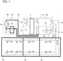
- Fig. 1 is a schematic view showing the overall configuration of an air-conditioning apparatus according to Embodiment 1, not making part of the present invention, but useful for its understanding.
- the air-conditioning apparatus includes a fan unit 1 and an outdoor unit 20 that are installed outside.
- the fan unit 1 includes an air-sending device 3 therein, and supplies conditioned air (hereinafter referred to as "supply air") to air-conditioned rooms 30 through an air supply duct 13, which will be described later, by operating the air-sending device 3.
- supply air conditioned air
- conditioned air is supplied to the rooms 30 by distributing the conditioned air via the air supply duct 13 and hence, the conditioned air can be supplied to the plurality of rooms 30 by one fan unit 1.
- Conditioned air indicates air conditioned to a certain temperature by an indoor heat exchanger 2 during an air conditioning and ventilation operation, which will be described later, or outside air taken into the fan unit 1 from the outside in a ventilation operation, which will be described later.
- the fan unit 1 includes a housing 1a having a cuboid shape, and the indoor heat exchanger 2, the air-sending device 3, an air return device 4, and a total heat exchanger 5 are disposed in the housing 1a.
- the housing 1a has an outside air port 6, an air supply port 7, a return air port 8, and an exhaust port 9 that are formed in a penetrating manner, the outside air port 6 taking air into the housing 1a from the outside, the air supply port 7 supplying the outside air taken into the housing 1a from the outside air port 6 to the rooms 30, the return air port 8 taking air into the housing 1a from the rooms 30, the exhaust port 9 exhausting the air taken into the housing 1a from the return air port 8 to the outside.
- a partition wall 10 is disposed in the housing 1a to extend in the horizontal direction. Due to the partition wall 10, the inside of the housing 1a is divided in a vertical direction to form an outside air passage 11A and an exhaust air passage 11B.
- the outside air passage 11A is formed in the lower portion of the housing 1a, and the exhaust air passage 11B is formed in the upper portion of the housing 1a.
- the air-conditioning apparatus is not limited to the configuration where the inside of the housing 1a is divided in the vertical direction, and may have a configuration where the inside of the housing 1a is divided in a lateral direction.
- the outside air passage 11A is an air passage that makes the outside air port 6 and the air supply port 7 communicate with each other, and that supplies outside air taken into the housing 1a from the outside air port 6 to the rooms 30 from the air supply port 7.
- the exhaust air passage 11B is an air passage that makes the return air port 8 and the exhaust port 9 communicate with each other, and that exhausts air of the rooms 30 taken into the housing 1a from the return air port 8 to the outside from the exhaust port 9.
- Outline arrows in Fig. 1 indicate the flow of air in the outside air passage 11A and the exhaust air passage 11B.
- the indoor heat exchanger 2 and the air-sending device 3 are disposed in the outside air passage 11A in that order from the upwind side.
- the air return device 4 is disposed in the exhaust air passage 11B.
- the total heat exchanger 5 is also disposed in the housing 1a in a shared manner with the outside air passage 11A and the exhaust air passage 11B such that the total heat exchanger 5 is disposed in an intermediate portion of the outside air passage 11A and in an intermediate portion of the exhaust air passage 11B.
- the total heat exchanger 5 is disposed on the upwind side of the indoor heat exchanger 2 in the outside air passage 11A, and is disposed on the upwind side of the air return device 4 in the exhaust air passage 11B.
- the air-sending device 3 is driven to generate an air flow directed toward the rooms 30 from the outside air port 6 via the air supply port 7 and the air supply duct 13, which will be described later.
- the air return device 4 is driven to generate an air flow directed toward the exhaust port 9 from the rooms 30 via a return air duct 14, which will be described later, and the return air port 8.
- the total heat exchanger 5 performs heat exchange between outside air taken into the housing 1a from the outside air port 6 and air of the rooms 30 taken into the housing 1a from the return air port 8.
- the total heat exchanger 5 is a device that performs heat exchange between outside air passing through the outside air passage 11A and exhaust air passing through the exhaust air passage 11B to recover energy of air conditioning that is lost due to ventilation with outside air.
- the total heat exchanger 5 is a rotary total heat exchanger having a configuration where a casing 5a is divided into an outside air side and an exhaust air side and a honeycomb rotor 5b is disposed in the casing 5a, the total heat exchanger 5 performing heat exchange by rotating the honeycomb rotor 5b.
- the total heat exchanger 5 is not limited to a rotary total heat exchanger, and may be a static total heat exchanger where an outside air flow passage and an exhaust air flow passage are partitioned by a planar sheet to form independent flow passages, and heat exchange is performed between outside air and exhaust air.
- the air supply duct 13 and the return air duct 14 are connected to the fan unit 1.
- the air supply duct 13 supplies air that passes through the outside air passage 11A to the respective rooms 30.
- the return air duct 14 causes air of the respective rooms 30 to be refluxed to the return air port 8.
- the air supply duct 13 makes the air supply port 7 and the respective rooms 30 communicate with each other.
- the air supply duct 13 extends from the air supply port 7 toward the respective rooms 30, and blows air toward the rooms 30 from air outlets 13a respectively provided to the rooms 30.
- the return air duct 14 extends from the return air port 8 toward the respective rooms 30, and suctions air of the rooms 30 from air inlets 14a respectively provided to the rooms 30 to return the air to the return air port 8.
- the air outlets 13a are located on the ceiling side of the rooms 30, and the air inlets 14a are located on the floor surface side of the rooms 30. As shown by solid line arrows in Fig. 1 , the flows of air from the ceiling side toward the floor surface side are formed in the rooms 30.
- the air supply port 7 is provided with an air supply damper 12 that opens and closes the air supply port 7.
- an air supply damper 12 that opens and closes the air supply port 7.
- the air supply damper 12 is open during the operation of the air-conditioning apparatus, and is closed during the stop of the operation of the air-conditioning apparatus. Opening and closing control of the air supply damper 12 is performed by a controller not shown in the drawing.
- the configuration of the fan unit 1 is not limited to the configuration where the air supply damper 12 is provided to the air supply port 7, and may be a configuration where the air supply damper 12 is provided to each air outlet 13a. Also in the case of the configuration where the air supply damper 12 is provided to each air outlet 13a, each air supply damper 12 is operated in the same manner as the case where the air supply damper 12 is provided to the air supply port 7. That is, each air supply damper 12 is open during the operation of the air-conditioning apparatus, and is closed during the stop of the air-conditioning apparatus.
- a position where the fan unit 1 is installed is not limited to the outside.
- the fan unit 1 may be installed in the room 30 provided that extension ducts are connected to the outside air port 6 and the exhaust port 9 and the end portions of the ducts are introduced to the outside for taking outside air into the fan unit 1 and for exhausting exhaust air to the outside.
- the outdoor unit 20 includes a compressor 21, a four-way valve 22, an outdoor heat exchanger 23, a pressure reducing device 24, and an outdoor air-sending device 25.
- the compressor 21 is equipment that compresses refrigerant to increase pressure and temperature of the refrigerant.
- a rotary compressor or a scroll compressor may be used, for example.
- the pressure reducing device 24 is a device that causes refrigerant to expand to reduce the pressure of the refrigerant.
- the pressure reducing device 24 may be an electronic expansion valve (LEV), for example.
- the compressor 21, the four-way valve 22, the outdoor heat exchanger 23, and the pressure reducing device 24 are installed in the outdoor unit 20, the indoor heat exchanger 2 is installed in the fan unit 1, and a refrigerant circuit through which refrigerant cycles is formed by connecting these components via refrigerant pipes 26.
- a specific pipe configuration is as follows. The refrigerant pipe 26 extending to the outside of the outdoor unit 20 from the outdoor unit 20 and the refrigerant pipe 26 extending to the outside of the fan unit 1 from the fan unit 1 are connected with each other via a metal connection portion (not shown in the drawing), such as a joint, to form the refrigerant circuit.
- the air-conditioning apparatus selectively performs the air conditioning and ventilation operation or the ventilation operation.
- ventilation is performed while a refrigeration cycle action is performed by causing refrigerant to cycle through the refrigerant circuit to perform air conditioning.
- ventilation operation only ventilation is performed without performing the refrigeration cycle action.
- the compressor 21 and the outdoor air-sending device 25 are operated, and the air-sending device 3 is operated.
- the air-conditioning apparatus can switch a cooling operation and a heating operation by switching the four-way valve 22 to reverse a direction in which refrigerant cycles in the refrigerant circuit.
- the compressor 21 and the outdoor air-sending device 25 are stopped, and the air-sending device 3 is operated.
- These operations of the air-conditioning apparatus can be controlled by a remote control or the like in the room 30.
- “during the operation of the air-conditioning apparatus” indicates that the air-conditioning apparatus performs the air conditioning and ventilation operation or the ventilation operation, so that at least the air-sending device 3 is operated.
- “during the stop of the air-conditioning apparatus” indicates that the air conditioning and ventilation operation or the ventilation operation of the air-conditioning apparatus is stopped, so that the compressor 21, the outdoor air-sending device 25, the air-sending device 3, and the air return device 4 are in a stopped state unless otherwise specified.
- refrigerant that cycles through the refrigerant circuit, it is desirable to use refrigerant having small global warming potential (GWP) from the viewpoint of global environmental protection.
- GWP global warming potential
- Refrigerant used in Embodiments is refrigerant having flammability and having greater average molecular weight than air. That is, refrigerant has greater density than air and is heavier than air under atmospheric pressure. Accordingly, the refrigerant has property of sinking downward in the direction of gravity in air.
- the air-conditioning apparatus In the air-conditioning apparatus, during the cooling operation, refrigerant cycles through the compressor 21, the outdoor heat exchanger 23, the pressure reducing device 24, and the indoor heat exchanger 2 in that order.
- the indoor heat exchanger 2 serves as an evaporator
- the outdoor heat exchanger 23 serves as a condenser.
- Refrigerant in a two-phase gas-liquid state with a temperature lower than a room temperature flows through the indoor heat exchanger 2. Therefore, air passing through the indoor heat exchanger 2 in the fan unit 1 is cooled by refrigerant, and the cooled air is supplied to the respective rooms 30, so that the respective rooms 30 are cooled.
- the air-conditioning apparatus In the air-conditioning apparatus, during the heating operation, refrigerant cycles through the compressor 21, the indoor heat exchanger 2, the pressure reducing device 24, and the outdoor heat exchanger 23 in that order.
- the indoor heat exchanger 2 serves as a condenser
- the outdoor heat exchanger 23 serves as an evaporator.
- Refrigerant in a two-phase gas-liquid state with a temperature higher than a room temperature flows through the indoor heat exchanger 2. Therefore, air passing through the indoor heat exchanger 2 in the fan unit 1 is heated by refrigerant, and the heated air is supplied to the respective rooms 30, so that the respective rooms 30 are heated.
- the refrigerant circuit performs the above-mentioned cooling operation.
- the air supply damper 12 is opened, and the air-sending device 3 and the air return device 4 are operated.
- the outside air passage 11A outside air is taken into the housing 1a from the outside air port 6 due to the operation of the air-sending device 3.
- the outside air taken into the housing 1a from the outside air port 6 passes through the total heat exchanger 5, the outside air exchanges heat with air passing through the exhaust air passage 11B.
- Warm outside air passing through the outside air passage 11A is caused to perform, in the total heat exchanger 5, total heat exchange with relatively cool air from the rooms 30 passing through the exhaust air passage 11B, thus being cooled, and the outside air is further cooled due to heat exchange with refrigerant in the indoor heat exchanger 2.
- Air that passes through the indoor heat exchanger 2 in the outside air passage 11A passes through the air-sending device 3 and the air supply port 7, is distributed through the air supply duct 13, and is supplied to the respective rooms 30 from the respective air outlets 13a. With such operations, the respective rooms 30 are cooled.
- Embodiment 1 the air conditioning and ventilation operation where the air-conditioning apparatus performs the refrigeration cycle action has been described. However, as described above, the air-conditioning apparatus may also perform the ventilation operation in which the refrigeration cycle action is not performed. During the ventilation operation, as described above, it is sufficient to stop the operation of the compressor 21 is stopped and to operate the air-sending device 3 and the air return device 4.
- the air supply damper 12 is open as described above.
- the air supply damper 12 is open as described above.
- the air supply damper 12 is stirred in each room 30 by an air flow generated by the air-sending device 3 and hence, the concentration of refrigerant in the room 30 does not become equal to or higher than flammable concentration whereby there is no possibility that a flammable region is formed in the room 30.
- the air supply damper 12 of the air-conditioning apparatus is closed. Therefore, in the air-conditioning apparatus, the flow of air from the outside air passage 11A to the rooms 30 is shut off. Accordingly, in the case where refrigerant leaks during the stop of the air-sending device 3, there is no possibility that refrigerant leaked in the fan unit 1 intrudes into the room 30. The leaked refrigerant flows through the outside air passage 11A in a direction opposite to a normal flow direction, and is discharged to the outside from the outside air port 6 that is open.
- the air supply damper 12 is closed and hence, even in the case where refrigerant leaks during the stop of the air-sending device 3, the air-conditioning apparatus can suppress formation of a flammable region in the room 30 due to refrigerant.
- the air supply damper 12 it is desirable to use a damper that is open during energization and is closed during non-energization.
- a damper for example, it is sufficient to use a damper that is opened by driving a motor and that is closed by a spring when energization is stopped.
- the air-conditioning apparatus can bring the air supply damper 12 into a closed state during power failure. Therefore, even if leakage of refrigerant occurs during power failure, it is possible to suppress formation of a flammable region in the room 30 due to refrigerant.
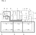
- the air-conditioning apparatus is not limited to a structure shown in Fig. 1 . As shown in Fig. 2 , which will be described next, the air-conditioning apparatus may also have a configuration where a damper is provided to each of the outside air port 6, the return air port 8, and the exhaust port 9.
- Fig. 2 is a schematic view showing a modification of the air-conditioning apparatus according to Embodiment 1, not making part of the present invention, but useful for its understanding.
- an outside air damper 15 is provided to the outside air port 6, a return air damper 16 is provided to the return air port 8, and an exhaust damper 17 is provided to the exhaust port 9.
- the outside air damper 15 and the exhaust damper 17 are closed.
- the outside air port 6 and the exhaust port 9 communicate with the outside and hence, by closing the outside air port 6 and the exhaust port 9 by using the outside air damper 15 and the exhaust damper 17, the air-conditioning apparatus can prevent intrusion of insects, small animals, or the like into the housing 1a.
- the return air damper 16 is open during the operation of the air-conditioning apparatus, and is closed during the stop of the air-conditioning apparatus. With such a configuration, the following can be achieved. During the stop of the air-conditioning apparatus, the return air damper 16 is closed and hence, for example, it is possible to prevent a situation where leaked refrigerant from the indoor heat exchanger 2 in the outside air passage 11A flows into the exhaust air passage 11B via the total heat exchanger 5, and intrudes into the room 30 from the return air duct 14. Further, the air-conditioning apparatus uses, for the return air damper 16, a damper that is open during energization and that is closed during non-energization.
- the return air damper 16 is brought into a closed state and hence, it is possible to suppress intrusion of leaked refrigerant into the room 30 during power failure. Opening and closing control of the outside air damper 15, the exhaust damper 17, and the return air damper 16 is performed by the controller not shown in the drawing. In general, even when the damper is closed, a slight gap is formed between the damper and an open port.
- the air-conditioning apparatus uses, for the air supply damper 12, a damper having a higher degree of airtightness than the return air damper 16, in other words, the air-conditioning apparatus uses, for the air supply damper 12, a damper having the highest degree of airtightness among four dampers and hence, it is possible to suppress intrusion of refrigerant into the room 30 with more certainty. That is, since leakage of refrigerant occurs in the indoor heat exchanger 2, by closing, to a high degree of airtightness, the air supply port 7 communicating with the outside air passage 11A in which the indoor heat exchanger 2 is disposed, the air-conditioning apparatus can suppress intrusion of refrigerant into the room 30 with more certainty.
- the air-conditioning apparatus of Embodiment 1 includes the housing 1a having the outside air port 6, the air supply port 7, the return air port 8, and the exhaust port 9, the outside air port 6 taking outside air into the housing 1a, the air supply port 7 supplying the outside air taken into the housing 1a from the outside air port 6 to the rooms 30, the return air port 8 taking air into the housing 1a from the rooms 30, the exhaust port 9 exhausting the air taken into the housing 1a from the return air port 8 to the outside.
- the air-conditioning apparatus also includes the air supply duct 13, the outside air passage 11A, and the exhaust air passage 11B, the air supply duct 13 making the air supply port 7 and the rooms 30 communicate with each other, the outside air passage 11A being formed in the housing 1a to make the outside air port 6 and the air supply port 7 communicate with each other, the exhaust air passage 11B being formed in the housing 1a in a separated manner from the outside air passage 11A to make the return air port 8 and the exhaust port 9 communicate with each other.
- the air-conditioning apparatus also includes the air-sending device 3, the indoor heat exchanger 2, and the air supply damper 12.
- the air-sending device 3 is disposed in the outside air passage 11A, and is configured to generate an air flow directed toward the rooms 30 from the outside air port 6 via the air supply port 7 and the air supply duct 13.
- the indoor heat exchanger 2 is disposed in the outside air passage 11A, and refrigerant flows through the indoor heat exchanger 2.
- the air supply damper 12 is open during the operation of the air-sending device 3, and is closed during the stop of the air-sending device 3.
- the air supply damper 12 is closed during the stop of the air-sending device 3 and hence, the air-conditioning apparatus can suppress formation of a flammable region in the room when the air-conditioning apparatus is in a stopped state.
- the air-conditioning apparatus of Embodiment 1 also includes the return air duct 14, the return air damper 16, the outside air damper 15, the exhaust damper 17, and the air return device 4, the return air duct 14 making the return air port 8 and the rooms 30 communicate with each other, the return air damper 16 opening and closing the return air port 8, the outside air damper 15 opening and closing the outside air port 6, the exhaust damper 17 opening and closing the exhaust port 9, the air return device 4 being disposed in the exhaust air passage 11B to generate an air flow directed toward the exhaust port 9 from the rooms 30 via the return air duct 14 and the return air port 8.
- the return air damper 16, the outside air damper 15, and the exhaust damper 17 are closed during the stop of the air-sending device 3 and the air return device 4.
- the air-conditioning apparatus may have a configuration where each open port is provided with a damper.
- the outside air damper 15 and the exhaust damper 17 that communicate with the outside are closed and hence, it is possible to prevent intrusion of insects, small animals, or the like into the housing 1a.
- the return air damper 16 is closed and hence, it is possible to prevent a situation where leaked refrigerant from the indoor heat exchanger 2 in the outside air passage 11A flows into the exhaust air passage 11B via the total heat exchanger 5, and intrudes into the room 30 from the return air duct 14.
- the degree of airtightness of the air supply damper 12 and the degree of airtightness of the return air damper 16 are higher than the degree of airtightness of the outside air damper 15 and the exhaust damper 17.
- the degree of airtightness of the air supply damper 12 is higher than the degree of airtightness of the return air damper 16.
- Embodiment 2 differs from Embodiment 1 in relation to the configuration of the housing 1a of the fan unit 1.
- Other components in Embodiment 2 are identical or equal to corresponding components in Embodiment 1.
- components that make Embodiment 2 different from Embodiment 1 will be mainly described.
- Components that are not described in Embodiment 2 are substantially equal to the corresponding components in Embodiment 1.
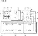
- Fig. 3 is a schematic view showing the overall configuration of an air-conditioning apparatus according to Embodiment 2.
- the housing 1a has an open port 40 that causes the outside air passage 11A to be open to the outside, and the open port 40 is provided with an open port damper 41 that opens and closes the open port 40.
- the open port damper 41 is closed during the operation of the air-conditioning apparatus, that is, during the operation of the air-sending device 3, and is open during the stop of the air-conditioning apparatus. That is, during the operation, the air supply damper 12 is open and the open port damper 41 is closed. During the stop, the air supply damper 12 is closed and the open port damper 41 is open. Opening and closing control of the air supply damper 12 and the open port damper 41 is performed by a controller not shown in the drawing.
- the open port damper 41 it is desirable to use a damper that is closed during energization and that is open during non-energization. For such a damper, for example, it is sufficient to use a damper that is closed by driving a motor, and is opened by a spring when energization is stopped.
- the open port damper 41 is closed and hence, there is no possibility that air in the outside air passage 11A leaks to the outside from the open port 40. Therefore, during the operation of the air-conditioning apparatus, there is no influence due to the open port 40 being provided, and the air-conditioning apparatus exhibits an air-conditioning effect from a normal air conditioning and ventilation operation or a normal ventilation operation.
- the open port damper 41 is open, so that the inside and the outside of the fan unit 1 are made to communicate with each other via the open port 40. Therefore, in the case where leakage of refrigerant occurs in the housing 1a during the stop of the air-conditioning apparatus, the air-conditioning apparatus can discharge leaked refrigerant to the outside of the fan unit 1 from the open port 40.
- the air supply damper 12 is closed during the stop of the air-conditioning apparatus and hence, in the case where leakage of refrigerant occurs in the housing 1a, there is no possibility of intrusion of refrigerant into the room 30 from the air supply port 7 via the air supply duct 13.
- a slight gap is formed between the damper and the open port.
- a gap may be formed between the damper and the open port due to deterioration of the damper over time or clogging of a foreign substance between the damper and the open port, for example. If such a gap is formed between the air supply damper 12 and the air supply port 7, even when the air supply damper 12 is closed, leaked refrigerant may intrude into the room 30 via the air supply port 7.
- Embodiment 2 is a mode preferable for such a case.
- the open port 40 that is open during the stop of the operation is provided to the housing 1a and hence, refrigerant leaked in the housing 1a is discharged to the outside from the open port 40 in priority to the gap formed between the air supply damper 12 and the air supply port 7.
- the open port 40 it is possible to suppress a situation where leaked refrigerant intrudes into the room 30 through the gap, thus forming a flammable region. It is sufficient to form the open port 40 at a position that allows the outside air passage 11A to be open to the outside.
- Fig. 3 shows an example where the open port 40 is provided to the bottom surface of the housing 1a at a position between the indoor heat exchanger 2 and the air supply port 7.
- the open port 40 is additionally provided with a net or the like for preventing intrusion of insects or small animals.
- the air-conditioning apparatus may also be configured such that, in the same manner as Embodiment 1, the outside air port 6 and the exhaust port 9 are respectively provided with the outside air damper 15 and the exhaust damper 17 that are closed during the stop of the operation to prevent intrusion of insects, small animals or the like from the outside air port 6 and the exhaust port 9.
- the return air damper 16 may be provided to the return air port 8.
- each of all four open ports is provided with a damper as described above, if no open port 40 is provided, there is a possibility that a flammable region is formed in the housing 1a when refrigerant leaks.
- the open port 40 is provided and hence, it is possible to suppress formation of a flammable region in the housing 1a when refrigerant leaks.
- the air-conditioning apparatus of Embodiment 2 can obtain advantageous effects substantially equal to the advantageous effects of Embodiment 1. Further, the air-conditioning apparatus of Embodiment 2 includes the open port 40 that causes the outside air passage 11A to be open to the outside and the open port damper 41 that opens the open port 40 during the stop of the operation and hence, the following advantageous effects can be obtained. That is, in the case where leakage of refrigerant occurs in the housing 1a during the stop of the operation, the air-conditioning apparatus of Embodiment 2 can efficiently discharge the refrigerant to the outside of the housing 1a from the open port 40 and hence, it is possible to suppress formation of a flammable region in the room 30.
- Embodiment 3 differs from Embodiment 1 in relation to the configuration of the housing 1a of the fan unit 1.
- Other components in Embodiment 3 are identical or equal to corresponding components in Embodiment 1.
- components that make Embodiment 3 different from Embodiment 1 will be mainly described.
- Components that are not described in Embodiment 3 are substantially equal to the corresponding components in Embodiment 1.
- Fig. 4 is a schematic view showing the overall configuration of an air-conditioning apparatus according to Embodiment 3.
- the partition wall 10 in the housing 1a of the fan unit 1 has a communication port 50 that makes the outside air passage 11A and the exhaust air passage 11B communicate with each other, and the communication port 50 is provided with a penetrated damper 51 that opens and closes the communication port 50.
- the penetrated damper 51 is closed during the operation of the air-conditioning apparatus, that is, during the operation of the air-sending device 3, and is open during the stop of the air-conditioning apparatus. Opening and closing control of the penetrated damper 51 is performed by a controller not shown in the drawing.
- the penetrated damper 51 it is desirable to use a damper that is closed during energization and that is open during non-energization.
- a damper for example, it is sufficient to use a damper that is closed by driving a motor and that is opened by a spring when energization is stopped.
- the return air port 8 is provided with the return air damper 16 that opens and closes the return air port 8.
- the air supply damper 12 and the return air damper 16 are open, and the penetrated damper 51 is close.
- the air supply damper 12 and the return air damper 16 are closed, and the penetrated damper 51 is open. Further, during the stop of the air-conditioning apparatus, the operation of the air-sending device 3 is stopped, but the operation of the air return device 4 is continued.
- the flow of air in the fan unit 1 during the operation of the air-conditioning apparatus is substantially equal to the flow of air in Embodiment 1 and, during the operation, the air-conditioning apparatus exhibits air-conditioning effect from a normal air conditioning and ventilation operation or a normal ventilation operation.
- the penetrated damper 51 is open, the air-sending device 3 is stopped, and the operation of the air return device 4 is continued.
- the operation of the air return device 4 is continued and hence, an air flow shown by solid line arrows in Fig. 4 is generated in the fan unit 1. That is, the following air flow is generated.
- outside air is taken into the outside air passage 11A in the housing 1a from the outside air port 6, and passes through the total heat exchanger 5 and the indoor heat exchanger 2. Thereafter, the outside air flows into the exhaust air passage 11B via the communication port 50, and passes through the total heat exchanger 5 and the air return device 4, and is then exhausted to the outside from the exhaust port 9.
- the air supply damper 12 and the return air damper 16 are closed and hence, there is no possibility that air is sent into the room 30.
- the position of the penetrated damper 51 is not limited to the position shown in Fig. 1 , and may be a position shown in Fig. 5 , which will be described next.
- Fig. 5 is a schematic view showing a modification of the air-conditioning apparatus according to Embodiment 3.
- the communication port 50 and the penetrated damper 51 are provided on the upwind side of the indoor heat exchanger 2.
- the present invention can be used for an air-conditioning apparatus that conditions air of a target room by using ducts.
Landscapes
- Engineering & Computer Science (AREA)
- Chemical & Material Sciences (AREA)
- Combustion & Propulsion (AREA)
- Mechanical Engineering (AREA)
- General Engineering & Computer Science (AREA)
- Air-Flow Control Members (AREA)
- Air Conditioning Control Device (AREA)
- Air Filters, Heat-Exchange Apparatuses, And Housings Of Air-Conditioning Units (AREA)
Priority Applications (6)
| Application Number | Priority Date | Filing Date | Title |
|---|---|---|---|
| EP21425035.9A EP4123233B1 (en) | 2021-07-23 | 2021-07-23 | Air-conditioning apparatus |
| CN202280049632.XA CN117693651A (zh) | 2021-07-23 | 2022-02-15 | 空调机 |
| PCT/JP2022/005925 WO2023002653A1 (ja) | 2021-07-23 | 2022-02-15 | 空気調和機 |
| AU2022313619A AU2022313619A1 (en) | 2021-07-23 | 2022-02-15 | Air conditioner |
| US18/564,196 US20240247824A1 (en) | 2021-07-23 | 2022-02-15 | Air-conditioning apparatus |
| JP2023536587A JPWO2023002653A1 (https=) | 2021-07-23 | 2022-02-15 |
Applications Claiming Priority (1)
| Application Number | Priority Date | Filing Date | Title |
|---|---|---|---|
| EP21425035.9A EP4123233B1 (en) | 2021-07-23 | 2021-07-23 | Air-conditioning apparatus |
Publications (2)
| Publication Number | Publication Date |
|---|---|
| EP4123233A1 EP4123233A1 (en) | 2023-01-25 |
| EP4123233B1 true EP4123233B1 (en) | 2024-08-28 |
Family
ID=77543458
Family Applications (1)
| Application Number | Title | Priority Date | Filing Date |
|---|---|---|---|
| EP21425035.9A Active EP4123233B1 (en) | 2021-07-23 | 2021-07-23 | Air-conditioning apparatus |
Country Status (6)
| Country | Link |
|---|---|
| US (1) | US20240247824A1 (https=) |
| EP (1) | EP4123233B1 (https=) |
| JP (1) | JPWO2023002653A1 (https=) |
| CN (1) | CN117693651A (https=) |
| AU (1) | AU2022313619A1 (https=) |
| WO (1) | WO2023002653A1 (https=) |
Families Citing this family (3)
| Publication number | Priority date | Publication date | Assignee | Title |
|---|---|---|---|---|
| WO2024252670A1 (ja) * | 2023-06-09 | 2024-12-12 | 三菱電機株式会社 | 外気処理ユニットおよび空気調和機 |
| WO2025197133A1 (ja) * | 2024-03-22 | 2025-09-25 | 三菱電機株式会社 | 同時給排形換気装置 |
| WO2025215854A1 (ja) * | 2024-04-08 | 2025-10-16 | 三菱電機株式会社 | 換気装置 |
Family Cites Families (7)
| Publication number | Priority date | Publication date | Assignee | Title |
|---|---|---|---|---|
| JP4496821B2 (ja) * | 2003-12-03 | 2010-07-07 | ダイキン工業株式会社 | 調湿装置 |
| JP5208100B2 (ja) * | 2009-12-18 | 2013-06-12 | 三菱電機株式会社 | 空気調和機 |
| KR101256780B1 (ko) * | 2013-01-24 | 2013-04-25 | (주)새한공조 | 직접 부하 제어 모드를 갖는 하이브리드 공조 시스템 |
| WO2015054303A1 (en) * | 2013-10-08 | 2015-04-16 | Johnson Controls Technology Company | Systems and methods for air conditioning a building using an energy recovery wheel |
| JP6851500B2 (ja) | 2017-11-15 | 2021-03-31 | 日立ジョンソンコントロールズ空調株式会社 | ダクト式空気調和機 |
| US10935454B2 (en) * | 2017-12-01 | 2021-03-02 | Johnson Controls Technology Company | Systems and methods for refrigerant leak management |
| WO2021050617A1 (en) * | 2019-09-13 | 2021-03-18 | Carrier Corporation | Hvac/r system with one or more leak mitigation dampers and method of diluting a leaked refrigerant in such a system |
-
2021
- 2021-07-23 EP EP21425035.9A patent/EP4123233B1/en active Active
-
2022
- 2022-02-15 WO PCT/JP2022/005925 patent/WO2023002653A1/ja not_active Ceased
- 2022-02-15 AU AU2022313619A patent/AU2022313619A1/en not_active Abandoned
- 2022-02-15 JP JP2023536587A patent/JPWO2023002653A1/ja active Pending
- 2022-02-15 CN CN202280049632.XA patent/CN117693651A/zh not_active Withdrawn
- 2022-02-15 US US18/564,196 patent/US20240247824A1/en active Pending
Also Published As
| Publication number | Publication date |
|---|---|
| CN117693651A (zh) | 2024-03-12 |
| US20240247824A1 (en) | 2024-07-25 |
| WO2023002653A1 (ja) | 2023-01-26 |
| EP4123233A1 (en) | 2023-01-25 |
| AU2022313619A1 (en) | 2023-12-14 |
| JPWO2023002653A1 (https=) | 2023-01-26 |
Similar Documents
| Publication | Publication Date | Title |
|---|---|---|
| US10928092B2 (en) | Usage-side air-conditioning apparatus and air-conditioning apparatus provided with same | |
| US20240247824A1 (en) | Air-conditioning apparatus | |
| EP2647920B1 (en) | Air-conditioning apparatus | |
| EP3045833B1 (en) | Refrigeration cycle device | |
| JP6701444B2 (ja) | 空気調和システム及びその冷媒量設定方法 | |
| JP6851500B2 (ja) | ダクト式空気調和機 | |
| JP5677461B2 (ja) | 冷凍サイクル装置の部品交換方法および冷凍サイクル装置 | |
| JPWO2002077535A1 (ja) | 空気調和装置及びその設置方法 | |
| JP2025010423A (ja) | 冷媒サイクルシステム | |
| EP2647930B1 (en) | Part replacement method for refrigeration cycle device | |
| JP2020183829A (ja) | 空調システム及び補助ファン | |
| EP3199881B1 (en) | Refrigeration cycle device | |
| EP4717986A1 (en) | Heat source unit and refrigeration apparatus | |
| WO2016046965A1 (ja) | 冷凍サイクル装置 |
Legal Events
| Date | Code | Title | Description |
|---|---|---|---|
| PUAI | Public reference made under article 153(3) epc to a published international application that has entered the european phase |
Free format text: ORIGINAL CODE: 0009012 |
|
| STAA | Information on the status of an ep patent application or granted ep patent |
Free format text: STATUS: THE APPLICATION HAS BEEN PUBLISHED |
|
| AK | Designated contracting states |
Kind code of ref document: A1 Designated state(s): AL AT BE BG CH CY CZ DE DK EE ES FI FR GB GR HR HU IE IS IT LI LT LU LV MC MK MT NL NO PL PT RO RS SE SI SK SM TR |
|
| STAA | Information on the status of an ep patent application or granted ep patent |
Free format text: STATUS: REQUEST FOR EXAMINATION WAS MADE |
|
| 17P | Request for examination filed |
Effective date: 20230511 |
|
| RBV | Designated contracting states (corrected) |
Designated state(s): AL AT BE BG CH CY CZ DE DK EE ES FI FR GB GR HR HU IE IS IT LI LT LU LV MC MK MT NL NO PL PT RO RS SE SI SK SM TR |
|
| STAA | Information on the status of an ep patent application or granted ep patent |
Free format text: STATUS: EXAMINATION IS IN PROGRESS |
|
| 17Q | First examination report despatched |
Effective date: 20231115 |
|
| GRAP | Despatch of communication of intention to grant a patent |
Free format text: ORIGINAL CODE: EPIDOSNIGR1 |
|
| STAA | Information on the status of an ep patent application or granted ep patent |
Free format text: STATUS: GRANT OF PATENT IS INTENDED |
|
| RIC1 | Information provided on ipc code assigned before grant |
Ipc: F24F 13/10 20060101ALI20240318BHEP Ipc: F24F 1/00 20190101ALI20240318BHEP Ipc: F24F 11/72 20180101ALI20240318BHEP Ipc: F24F 3/00 20060101AFI20240318BHEP |
|
| INTG | Intention to grant announced |
Effective date: 20240409 |
|
| GRAS | Grant fee paid |
Free format text: ORIGINAL CODE: EPIDOSNIGR3 |
|
| GRAA | (expected) grant |
Free format text: ORIGINAL CODE: 0009210 |
|
| STAA | Information on the status of an ep patent application or granted ep patent |
Free format text: STATUS: THE PATENT HAS BEEN GRANTED |
|
| AK | Designated contracting states |
Kind code of ref document: B1 Designated state(s): AL AT BE BG CH CY CZ DE DK EE ES FI FR GB GR HR HU IE IS IT LI LT LU LV MC MK MT NL NO PL PT RO RS SE SI SK SM TR |
|
| RAP3 | Party data changed (applicant data changed or rights of an application transferred) |
Owner name: MITSUBISHI ELECTRIC HYDRONICS &IT COOLING SYSTEMS S.P.A. Owner name: MITSUBISHI ELECTRIC CORPORATION |
|
| REG | Reference to a national code |
Ref country code: CH Ref legal event code: EP |
|
| REG | Reference to a national code |
Ref country code: DE Ref legal event code: R096 Ref document number: 602021017894 Country of ref document: DE |
|
| P01 | Opt-out of the competence of the unified patent court (upc) registered |
Free format text: CASE NUMBER: APP_47999/2024 Effective date: 20240821 |
|
| REG | Reference to a national code |
Ref country code: IE Ref legal event code: FG4D |
|
| REG | Reference to a national code |
Ref country code: LT Ref legal event code: MG9D |
|
| PG25 | Lapsed in a contracting state [announced via postgrant information from national office to epo] |
Ref country code: NO Free format text: LAPSE BECAUSE OF FAILURE TO SUBMIT A TRANSLATION OF THE DESCRIPTION OR TO PAY THE FEE WITHIN THE PRESCRIBED TIME-LIMIT Effective date: 20241128 |
|
| REG | Reference to a national code |
Ref country code: AT Ref legal event code: MK05 Ref document number: 1718313 Country of ref document: AT Kind code of ref document: T Effective date: 20240828 |
|
| PG25 | Lapsed in a contracting state [announced via postgrant information from national office to epo] |
Ref country code: NL Free format text: LAPSE BECAUSE OF FAILURE TO SUBMIT A TRANSLATION OF THE DESCRIPTION OR TO PAY THE FEE WITHIN THE PRESCRIBED TIME-LIMIT Effective date: 20240828 Ref country code: PL Free format text: LAPSE BECAUSE OF FAILURE TO SUBMIT A TRANSLATION OF THE DESCRIPTION OR TO PAY THE FEE WITHIN THE PRESCRIBED TIME-LIMIT Effective date: 20240828 Ref country code: GR Free format text: LAPSE BECAUSE OF FAILURE TO SUBMIT A TRANSLATION OF THE DESCRIPTION OR TO PAY THE FEE WITHIN THE PRESCRIBED TIME-LIMIT Effective date: 20241129 Ref country code: FI Free format text: LAPSE BECAUSE OF FAILURE TO SUBMIT A TRANSLATION OF THE DESCRIPTION OR TO PAY THE FEE WITHIN THE PRESCRIBED TIME-LIMIT Effective date: 20240828 Ref country code: PT Free format text: LAPSE BECAUSE OF FAILURE TO SUBMIT A TRANSLATION OF THE DESCRIPTION OR TO PAY THE FEE WITHIN THE PRESCRIBED TIME-LIMIT Effective date: 20241230 |
|
| PG25 | Lapsed in a contracting state [announced via postgrant information from national office to epo] |
Ref country code: BG Free format text: LAPSE BECAUSE OF FAILURE TO SUBMIT A TRANSLATION OF THE DESCRIPTION OR TO PAY THE FEE WITHIN THE PRESCRIBED TIME-LIMIT Effective date: 20240828 |
|
| PG25 | Lapsed in a contracting state [announced via postgrant information from national office to epo] |
Ref country code: LV Free format text: LAPSE BECAUSE OF FAILURE TO SUBMIT A TRANSLATION OF THE DESCRIPTION OR TO PAY THE FEE WITHIN THE PRESCRIBED TIME-LIMIT Effective date: 20240828 |
|
| REG | Reference to a national code |
Ref country code: NL Ref legal event code: MP Effective date: 20240828 |
|
| PG25 | Lapsed in a contracting state [announced via postgrant information from national office to epo] |
Ref country code: AT Free format text: LAPSE BECAUSE OF FAILURE TO SUBMIT A TRANSLATION OF THE DESCRIPTION OR TO PAY THE FEE WITHIN THE PRESCRIBED TIME-LIMIT Effective date: 20240828 Ref country code: IS Free format text: LAPSE BECAUSE OF FAILURE TO SUBMIT A TRANSLATION OF THE DESCRIPTION OR TO PAY THE FEE WITHIN THE PRESCRIBED TIME-LIMIT Effective date: 20241228 |
|
| PG25 | Lapsed in a contracting state [announced via postgrant information from national office to epo] |
Ref country code: HR Free format text: LAPSE BECAUSE OF FAILURE TO SUBMIT A TRANSLATION OF THE DESCRIPTION OR TO PAY THE FEE WITHIN THE PRESCRIBED TIME-LIMIT Effective date: 20240828 |
|
| PG25 | Lapsed in a contracting state [announced via postgrant information from national office to epo] |
Ref country code: ES Free format text: LAPSE BECAUSE OF FAILURE TO SUBMIT A TRANSLATION OF THE DESCRIPTION OR TO PAY THE FEE WITHIN THE PRESCRIBED TIME-LIMIT Effective date: 20240828 Ref country code: RS Free format text: LAPSE BECAUSE OF FAILURE TO SUBMIT A TRANSLATION OF THE DESCRIPTION OR TO PAY THE FEE WITHIN THE PRESCRIBED TIME-LIMIT Effective date: 20241128 |
|
| PG25 | Lapsed in a contracting state [announced via postgrant information from national office to epo] |
Ref country code: RS Free format text: LAPSE BECAUSE OF FAILURE TO SUBMIT A TRANSLATION OF THE DESCRIPTION OR TO PAY THE FEE WITHIN THE PRESCRIBED TIME-LIMIT Effective date: 20241128 Ref country code: PT Free format text: LAPSE BECAUSE OF FAILURE TO SUBMIT A TRANSLATION OF THE DESCRIPTION OR TO PAY THE FEE WITHIN THE PRESCRIBED TIME-LIMIT Effective date: 20241230 Ref country code: PL Free format text: LAPSE BECAUSE OF FAILURE TO SUBMIT A TRANSLATION OF THE DESCRIPTION OR TO PAY THE FEE WITHIN THE PRESCRIBED TIME-LIMIT Effective date: 20240828 Ref country code: NO Free format text: LAPSE BECAUSE OF FAILURE TO SUBMIT A TRANSLATION OF THE DESCRIPTION OR TO PAY THE FEE WITHIN THE PRESCRIBED TIME-LIMIT Effective date: 20241128 Ref country code: NL Free format text: LAPSE BECAUSE OF FAILURE TO SUBMIT A TRANSLATION OF THE DESCRIPTION OR TO PAY THE FEE WITHIN THE PRESCRIBED TIME-LIMIT Effective date: 20240828 Ref country code: LV Free format text: LAPSE BECAUSE OF FAILURE TO SUBMIT A TRANSLATION OF THE DESCRIPTION OR TO PAY THE FEE WITHIN THE PRESCRIBED TIME-LIMIT Effective date: 20240828 Ref country code: IS Free format text: LAPSE BECAUSE OF FAILURE TO SUBMIT A TRANSLATION OF THE DESCRIPTION OR TO PAY THE FEE WITHIN THE PRESCRIBED TIME-LIMIT Effective date: 20241228 Ref country code: HR Free format text: LAPSE BECAUSE OF FAILURE TO SUBMIT A TRANSLATION OF THE DESCRIPTION OR TO PAY THE FEE WITHIN THE PRESCRIBED TIME-LIMIT Effective date: 20240828 Ref country code: GR Free format text: LAPSE BECAUSE OF FAILURE TO SUBMIT A TRANSLATION OF THE DESCRIPTION OR TO PAY THE FEE WITHIN THE PRESCRIBED TIME-LIMIT Effective date: 20241129 Ref country code: FI Free format text: LAPSE BECAUSE OF FAILURE TO SUBMIT A TRANSLATION OF THE DESCRIPTION OR TO PAY THE FEE WITHIN THE PRESCRIBED TIME-LIMIT Effective date: 20240828 Ref country code: ES Free format text: LAPSE BECAUSE OF FAILURE TO SUBMIT A TRANSLATION OF THE DESCRIPTION OR TO PAY THE FEE WITHIN THE PRESCRIBED TIME-LIMIT Effective date: 20240828 Ref country code: BG Free format text: LAPSE BECAUSE OF FAILURE TO SUBMIT A TRANSLATION OF THE DESCRIPTION OR TO PAY THE FEE WITHIN THE PRESCRIBED TIME-LIMIT Effective date: 20240828 Ref country code: AT Free format text: LAPSE BECAUSE OF FAILURE TO SUBMIT A TRANSLATION OF THE DESCRIPTION OR TO PAY THE FEE WITHIN THE PRESCRIBED TIME-LIMIT Effective date: 20240828 |
|
| PG25 | Lapsed in a contracting state [announced via postgrant information from national office to epo] |
Ref country code: DK Free format text: LAPSE BECAUSE OF FAILURE TO SUBMIT A TRANSLATION OF THE DESCRIPTION OR TO PAY THE FEE WITHIN THE PRESCRIBED TIME-LIMIT Effective date: 20240828 Ref country code: RO Free format text: LAPSE BECAUSE OF FAILURE TO SUBMIT A TRANSLATION OF THE DESCRIPTION OR TO PAY THE FEE WITHIN THE PRESCRIBED TIME-LIMIT Effective date: 20240828 Ref country code: SM Free format text: LAPSE BECAUSE OF FAILURE TO SUBMIT A TRANSLATION OF THE DESCRIPTION OR TO PAY THE FEE WITHIN THE PRESCRIBED TIME-LIMIT Effective date: 20240828 |
|
| PG25 | Lapsed in a contracting state [announced via postgrant information from national office to epo] |
Ref country code: EE Free format text: LAPSE BECAUSE OF FAILURE TO SUBMIT A TRANSLATION OF THE DESCRIPTION OR TO PAY THE FEE WITHIN THE PRESCRIBED TIME-LIMIT Effective date: 20240828 |
|
| PG25 | Lapsed in a contracting state [announced via postgrant information from national office to epo] |
Ref country code: CZ Free format text: LAPSE BECAUSE OF FAILURE TO SUBMIT A TRANSLATION OF THE DESCRIPTION OR TO PAY THE FEE WITHIN THE PRESCRIBED TIME-LIMIT Effective date: 20240828 |
|
| PG25 | Lapsed in a contracting state [announced via postgrant information from national office to epo] |
Ref country code: SK Free format text: LAPSE BECAUSE OF FAILURE TO SUBMIT A TRANSLATION OF THE DESCRIPTION OR TO PAY THE FEE WITHIN THE PRESCRIBED TIME-LIMIT Effective date: 20240828 |
|
| REG | Reference to a national code |
Ref country code: DE Ref legal event code: R097 Ref document number: 602021017894 Country of ref document: DE |
|
| PLBE | No opposition filed within time limit |
Free format text: ORIGINAL CODE: 0009261 |
|
| STAA | Information on the status of an ep patent application or granted ep patent |
Free format text: STATUS: NO OPPOSITION FILED WITHIN TIME LIMIT |
|
| 26N | No opposition filed |
Effective date: 20250530 |
|
| PG25 | Lapsed in a contracting state [announced via postgrant information from national office to epo] |
Ref country code: SE Free format text: LAPSE BECAUSE OF FAILURE TO SUBMIT A TRANSLATION OF THE DESCRIPTION OR TO PAY THE FEE WITHIN THE PRESCRIBED TIME-LIMIT Effective date: 20240828 |
|
| REG | Reference to a national code |
Ref country code: DE Ref legal event code: R119 Ref document number: 602021017894 Country of ref document: DE |
|
| REG | Reference to a national code |
Ref country code: CH Ref legal event code: H13 Free format text: ST27 STATUS EVENT CODE: U-0-0-H10-H13 (AS PROVIDED BY THE NATIONAL OFFICE) Effective date: 20260224 |
|
| PG25 | Lapsed in a contracting state [announced via postgrant information from national office to epo] |
Ref country code: LU Free format text: LAPSE BECAUSE OF NON-PAYMENT OF DUE FEES Effective date: 20250723 |
|
| GBPC | Gb: european patent ceased through non-payment of renewal fee |
Effective date: 20250723 |
|
| REG | Reference to a national code |
Ref country code: BE Ref legal event code: MM Effective date: 20250731 |
|
| PG25 | Lapsed in a contracting state [announced via postgrant information from national office to epo] |
Ref country code: GB Free format text: LAPSE BECAUSE OF NON-PAYMENT OF DUE FEES Effective date: 20250723 |
|
| PG25 | Lapsed in a contracting state [announced via postgrant information from national office to epo] |
Ref country code: DE Free format text: LAPSE BECAUSE OF NON-PAYMENT OF DUE FEES Effective date: 20260203 |
|
| PG25 | Lapsed in a contracting state [announced via postgrant information from national office to epo] |
Ref country code: BE Free format text: LAPSE BECAUSE OF NON-PAYMENT OF DUE FEES Effective date: 20250731 |
|
| PG25 | Lapsed in a contracting state [announced via postgrant information from national office to epo] |
Ref country code: FR Free format text: LAPSE BECAUSE OF NON-PAYMENT OF DUE FEES Effective date: 20250731 |