EP4123207A1 - Expansion pipe joint and incineration ash treatment facility - Google Patents
Expansion pipe joint and incineration ash treatment facility Download PDFInfo
- Publication number
- EP4123207A1 EP4123207A1 EP21770934.4A EP21770934A EP4123207A1 EP 4123207 A1 EP4123207 A1 EP 4123207A1 EP 21770934 A EP21770934 A EP 21770934A EP 4123207 A1 EP4123207 A1 EP 4123207A1
- Authority
- EP
- European Patent Office
- Prior art keywords
- flange
- expansion joint
- axial direction
- peripheral portion
- outer tube
- Prior art date
- Legal status (The legal status is an assumption and is not a legal conclusion. Google has not performed a legal analysis and makes no representation as to the accuracy of the status listed.)
- Granted
Links
Images



Classifications
-
- F—MECHANICAL ENGINEERING; LIGHTING; HEATING; WEAPONS; BLASTING
- F16—ENGINEERING ELEMENTS AND UNITS; GENERAL MEASURES FOR PRODUCING AND MAINTAINING EFFECTIVE FUNCTIONING OF MACHINES OR INSTALLATIONS; THERMAL INSULATION IN GENERAL
- F16L—PIPES; JOINTS OR FITTINGS FOR PIPES; SUPPORTS FOR PIPES, CABLES OR PROTECTIVE TUBING; MEANS FOR THERMAL INSULATION IN GENERAL
- F16L27/00—Adjustable joints; Joints allowing movement
- F16L27/10—Adjustable joints; Joints allowing movement comprising a flexible connection only
- F16L27/107—Adjustable joints; Joints allowing movement comprising a flexible connection only the ends of the pipe being interconnected by a flexible sleeve
- F16L27/108—Adjustable joints; Joints allowing movement comprising a flexible connection only the ends of the pipe being interconnected by a flexible sleeve the sleeve having the form of a bellows with only one corrugation
-
- F—MECHANICAL ENGINEERING; LIGHTING; HEATING; WEAPONS; BLASTING
- F16—ENGINEERING ELEMENTS AND UNITS; GENERAL MEASURES FOR PRODUCING AND MAINTAINING EFFECTIVE FUNCTIONING OF MACHINES OR INSTALLATIONS; THERMAL INSULATION IN GENERAL
- F16L—PIPES; JOINTS OR FITTINGS FOR PIPES; SUPPORTS FOR PIPES, CABLES OR PROTECTIVE TUBING; MEANS FOR THERMAL INSULATION IN GENERAL
- F16L27/00—Adjustable joints; Joints allowing movement
- F16L27/12—Adjustable joints; Joints allowing movement allowing substantial longitudinal adjustment or movement
-
- B—PERFORMING OPERATIONS; TRANSPORTING
- B02—CRUSHING, PULVERISING, OR DISINTEGRATING; PREPARATORY TREATMENT OF GRAIN FOR MILLING
- B02C—CRUSHING, PULVERISING, OR DISINTEGRATING IN GENERAL; MILLING GRAIN
- B02C23/00—Auxiliary methods or auxiliary devices or accessories specially adapted for crushing or disintegrating not provided for in preceding groups or not specially adapted to apparatus covered by a single preceding group
- B02C23/02—Feeding devices
-
- F—MECHANICAL ENGINEERING; LIGHTING; HEATING; WEAPONS; BLASTING
- F16—ENGINEERING ELEMENTS AND UNITS; GENERAL MEASURES FOR PRODUCING AND MAINTAINING EFFECTIVE FUNCTIONING OF MACHINES OR INSTALLATIONS; THERMAL INSULATION IN GENERAL
- F16L—PIPES; JOINTS OR FITTINGS FOR PIPES; SUPPORTS FOR PIPES, CABLES OR PROTECTIVE TUBING; MEANS FOR THERMAL INSULATION IN GENERAL
- F16L51/00—Expansion-compensation arrangements for pipe-lines
- F16L51/02—Expansion-compensation arrangements for pipe-lines making use of a bellows or an expansible folded or corrugated tube
- F16L51/022—Expansion-compensation arrangements for pipe-lines making use of a bellows or an expansible folded or corrugated tube with a single corrugation
-
- F—MECHANICAL ENGINEERING; LIGHTING; HEATING; WEAPONS; BLASTING
- F23—COMBUSTION APPARATUS; COMBUSTION PROCESSES
- F23J—REMOVAL OR TREATMENT OF COMBUSTION PRODUCTS OR COMBUSTION RESIDUES; FLUES
- F23J3/00—Removing solid residues from passages or chambers beyond the fire, e.g. from flues by soot blowers
- F23J3/06—Systems for accumulating residues from different parts of furnace plant
-
- B—PERFORMING OPERATIONS; TRANSPORTING
- B02—CRUSHING, PULVERISING, OR DISINTEGRATING; PREPARATORY TREATMENT OF GRAIN FOR MILLING
- B02C—CRUSHING, PULVERISING, OR DISINTEGRATING IN GENERAL; MILLING GRAIN
- B02C17/00—Disintegrating by tumbling mills, i.e. mills having a container charged with the material to be disintegrated with or without special disintegrating members such as pebbles or balls
- B02C17/14—Mills in which the charge to be ground is turned over by movements of the container other than by rotating, e.g. by swinging, vibrating, tilting
-
- F—MECHANICAL ENGINEERING; LIGHTING; HEATING; WEAPONS; BLASTING
- F23—COMBUSTION APPARATUS; COMBUSTION PROCESSES
- F23J—REMOVAL OR TREATMENT OF COMBUSTION PRODUCTS OR COMBUSTION RESIDUES; FLUES
- F23J2700/00—Ash removal, handling and treatment means; Ash and slag handling in pulverulent fuel furnaces; Ash removal means for incinerators
- F23J2700/003—Ash removal means for incinerators
Definitions
- the present disclosure relates to expansion joints in piping systems through which powdery or granular materials are transferred and in particular to an expansion joint that is located at a point of connection of pipes in a region where a powdery or granular material is transferred by gravity and that absorbs displacement between the connected pipes.
- the present disclosure also relates to incineration ash treatment equipment including the expansion pipe.
- the expansion joint of Patent Literature 1 includes an outer tube, an inner tube located inside the outer tube, and an elastic closure (bellows) closing a gap between the upstream ends of the inner and outer tubes.
- the downstream end of the outer tube is connected to a downstream pipe, and the upstream end of the inner tube is connected to an upstream pipe.
- the upstream ends of the inner and outer tubes are located at substantially the same height.
- the downstream end of the inner tube and the closure are far enough from each other to prevent contact between the closure and a hot transferred material getting in between the inner and outer tubes.
- Expansion joints are inserted between upstream and downstream pipes placed beforehand. Expansion joints are heavy, and may be located at great heights or in narrow places. With the use of the expansion joint of Patent Literature 1 in such a situation, the expansion joint mounting work including connecting the inner tube to the upstream pipe and attaching the closure could be cumbersome because the upstream end of the outer tube, the upstream end of the inner tube, and the downstream end of the upstream pipe are located at substantially the same height.
- the present disclosure has been made in view of the above circumstances, and an object of the present disclosure is to propose an expansion joint in which the downstream end of an inner tube and a closure are far enough from each other and which can easily be mounted and removed.
- An expansion joint is an expansion joint that absorbs displacement occurring at a point of connection between upstream and downstream pipes through which a powdery and/or granular material is transferred by gravity, the expansion joint including:
- Incineration ash treatment equipment includes: a vibrator that treats incineration ash; a pipe that delivers the incineration ash to the vibrator; and the expansion joint as defined above, the expansion joint being located between an outlet of the pipe and an inlet of the vibrator.
- the middle flange, to which the closure is attached is spaced from the fourth end (i.e., downstream end) of the inner tube in the axial direction.
- the fourth end of the inner tube and the closure can be spaced a distance corresponding to the distance between the fourth end and middle flange of the inner tube in the axial direction. This can reduce the likelihood that the transferred material entering the gap between the inner tube and the outer tube from the fourth end of the inner tube comes into contact with the closure 4.
- the first flange located at the first end of the outer tube and the third flange located at the third end of the inner tube are spaced from each other in the axial direction.
- the space between the first flange and the third flange in the axial direction can be used as a workspace for connection (or disconnection) of the third flange and the upstream pipe.
- connection and disconnection of the expansion joint and the upstream pipe can easily be performed.
- the third end of the inner tube connected to the upstream pipe and the first end of the outer tube are spaced from each other in the axial direction.
- the dimension of the outer tube in the axial direction is smaller than the vertical dimension of a mounting region extending between the upstream pipe and the downstream pipe.
- the outer tube with the inner tube inserted therein can easily be carried into the mounting region.
- the closure can be carried into the mounting region by utilizing a gap between the upstream pipe and the outer tube.
- the space between the third flange and the middle flange in the axial direction can be used as a workspace for attachment (or detachment) of the closure.
- attachment and detachment of the closure are easy.
- the present disclosure can propose an expansion joint in which the downstream end of an inner tube and a closure are far enough from each other and which can easily be mounted and removed.
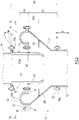
- FIG. 1 shows a schematic configuration of incineration ash treatment equipment 7 including an expansion joint 10 according to an exemplary embodiment of the present disclosure.
- the incineration ash treatment equipment 7 is adapted to finely grind incineration ash generated, for example, in a coal-fired boiler or garbage incinerator.
- the incineration ash treatment equipment 7 of FIG. 1 includes a grinder 75 that finely grinds incineration ash 70, a conveyor 74 that transfers the incineration ash 70 to the grinder 75, and a hopper 76 that receives the incineration ash 70 ground by the grinder 75.
- a vibrating mill can be used as the grinder 75. In a typical vibrating mill, a grinding medium and a material to be ground collides with each other in a rapidly vibrating drum, and thus the material is finely ground.
- the conveyor 74 and the grinder 75 are connected by a piping system through which the incineration ash 70 in the form of grains or aggregates is transferred.
- the piping system includes a vibrating pipe 78 coupled to the inlet of the grinder 75, a fixed pipe 77 located upstream of the vibrating pipe 78, and an expansion joint 10 connecting the fixed pipe 77 to the vibrating pipe 78.
- upstream and downstream respectively refer to upstream and downstream in the direction of flow of the material (incineration ash 70) transferred through the piping system.
- the fixed pipe 77 is an "upstream pipe” for the expansion joint 10
- the vibrating pipe 78 is a "downstream pipe" for the expansion joint 10.
- the fixed pipe 77 is fixed relative to a structure including a device upstream of the grinder 75 (the device is, for example, the conveyor 74 or an unshown device used for another coal treatment process).
- the vibrating pipe 78 vibrates in conjunction with vibration of the drum of the grinder 75.
- displacement occurs at a point of connection between the fixed pipe 77 and the vibrating pipe 78 due to the vibration of the vibrating pipe 78.
- the expansion joint 10 absorbs the displacement occurring at the point of connection between the fixed pipe 77 and the vibrating pipe 78.
- the expansion joint 10 according to the present disclosure is applicable also in the case where both the fixed pipe 77 and the vibrating pipe 78 are movable.
- FIG. 2 shows the expansion joint 10 according to an exemplary embodiment of the present disclosure and is an end view of the expansion joint 10 cut along a plane including the central axis of the expansion joint 10.
- the expansion joint 10 is generally shaped as a solid of revolution.
- the direction in which the axis of revolution extends is referred to as the "axial direction X" of the expansion joint 10, and the axis of revolution is referred to as the "central axis" of the expansion joint 10.
- the expansion joint 10 is mounted in a space between the fixed pipe 77 and the vibrating pipe 78 in the up-down direction.
- the space between the fixed pipe 77 and the vibrating pipe 78 in the up-down direction will be referred to as a "mounting region A" hereinafter.
- a straight line drawn between the center of the opening of the fixed pipe 77 and the center of the opening of the vibrating pipe 78 is parallel to the axial direction X of the expansion joint 10.
- the expansion joint 10 of FIG. 2 includes an outer tube 2, an inner tube 3 located inside the outer tube 2, and a closure 4 closing a gap between the outer tube 2 and the inner tube 3.
- the inner circumference of the inner tube 3 defines a transfer path 11 along which the transferred material (e.g., the incineration ash 70) flows through the expansion joint 10.
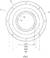
- FIG. 3 shows the outer tube 2 as viewed in the axial direction X.
- the outer tube 2 is a metallic tubular body extending from its upstream end (first end) to its downstream end (second end) in the axial direction X.
- the outer tube 2 includes a first flange 21 located at the upstream end of the outer tube 2, a second flange 22 located at the downstream end of the outer tube 2, a barrel 23 connecting the first flange 21 to the second flange 22, and a baffle plate 24 located on the inner circumference of the barrel 23.
- Each of the first and second flanges 21 and 22 includes circumferentially arranged insertion holes. Bolts are inserted into the insertion holes.
- the second flange 22 is connected to an inlet flange 78a located at the upstream end of the vibrating pipe 78. Between the second flange 22 and the inlet flange 78a there is a lower gasket 37 that provides hermeticity.
- the outer tube 2 vibrates in conjunction with vibration of the vibrating pipe 78.
- the inner diameter D21 of the first flange 21 is greater than the inner diameter D22 of the second flange 22.
- the barrel 23 is tapered downward to smoothly connect the first and second flanges 21 and 22 having different inner diameters.
- the outer tube 2 structured as described above can ensure a range over which the outer tube 2 is displaceable relative to the inner tube 3 in a direction perpendicular to the axial direction X and at the same time allow for quick movement or transfer of the material from the outer tube 2 to the vibrating pipe 78.
- the baffle plate 24 serves to prevent the transferred material accumulated in the transfer path 11 of the expansion joint 10 from entering the gap between the outer tube 2 and the inner tube 3.
- the baffle plate 24 is shaped as an annular disc and located at approximately the center of the barrel 23 in the axial direction X.
- the inner diameter D24a of the baffle plate 24 is greater than the inner diameter D22 of the second flange 22.
- the outer diameter D24b of the baffle plate 24 is smaller than the inner diameter D21 of the first flange 21.
- the outer periphery of the baffle plate 24 is welded to the inner circumferential surface of the barrel 23.
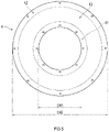
- FIG. 4 shows the inner tube 3 as viewed in the axial direction X.
- the inner tube 3 is a metallic tubular body extending from its upstream end (third end) to its downstream end (fourth end) in the axial direction X.
- the inner tube 3 includes a third flange 31 located at the upstream end of the inner tube 3, a barrel 32 extending downward from the third flange 31, and a middle flange 33 located at a middle portion of the barrel 32 in the axial direction X.
- the middle flange 33 includes circumferentially arranged insertion holes. Bolts are inserted into the insertion holes.
- the third flange 31 is connected to an outlet flange 77a located at the downstream end of the fixed pipe 77.
- the outer diameter D31 of the third flange 31 is smaller than the outer diameter of the outlet flange 77a.
- the third flange 31 is placed between retainers 25 and the outlet flange 77a, and the retainers 25, outlet flange 77a, and third flange 31 are fastened together by bolts inserted through the retainers 25 and the outlet flange 77a.
- the retainers 25 (the number of which is, for example, four) are arranged along the outer periphery of the third flange 31.
- Each of the retainers 25 is shaped as a segment of a ring, and the retainers 25 form the ring together.
- Each of the retainers 25 includes a cut at its upper inner periphery, and the third flange 31 is fitted in the cut.
- the third flange 31 of the inner tube 3 is restricted from moving relative to the outlet flange 77a of the fixed pipe 77 in the radial and up-down directions in the event that the point of connection between the fixed pipe 77 and the inner tube 3 is subjected to vibration.
- Each of the retainers 25 includes at least one insertion hole 25a for insertion of a bolt. Between the retainers 25 and the outlet flange 77a there is an upper gasket 36 that provides hermeticity.
- the middle flange 33 protrudes radially outward from the outer circumferential surface of the barrel 32.
- the outer diameter D33 of the middle flange 33 is greater than the inner diameter D24a of the baffle plate 24 and smaller than the outer diameter D24b of the baffle plate 24.
- the outer diameter D31 of the third flange 31 is desirably smaller than the outer diameter D33 of the middle flange 33.
- FIG. 5 shows the closure 4 as viewed in the axial direction X.
- the closure 4 is shaped as an annular disc.
- the closure 4 includes an inner peripheral portion 41, an outer peripheral portion 42, and an elastic portion 43 located between the inner peripheral portion 41 and the outer peripheral portion 42.
- Each of the inner and outer peripheral portions 41 and 42 includes circumferentially arranged insertion holes. Bolts are inserted into the insertion holes.
- the inner diameter D41 of the closure 4 is greater than the outer diameter D32 of the barrel 32 of the inner tube 3 (i.e., the inner diameter of the middle flange 33) and smaller than the outer diameter D33 of the middle flange 33.
- the outer diameter D42 of the closure 4 is greater than the inner diameter D21 of the first flange 21 of the outer tube 2.
- FIG. 6 is a view taken along the arrow VI-VI of FIG. 2 .
- the inner peripheral portion 41 of the closure 4 is connected to the middle flange 33 of the inner tube 3.
- the inner peripheral portion 41 is placed between the middle flange 33 of the inner tube 3 and retainers 28, and the retainers 28, inner peripheral portion 41, and middle flange 33 are fastened together by bolts inserted through the retainers 28, inner peripheral portion 41, and middle flange 33.
- the retainers 28 (the number of which is, for example, four) are arranged in a ring along the inner peripheral portion 41.
- Each of the retainers 28 is shaped as a segment of a ring, and the retainers 28 form the ring together.
- the outer peripheral portion 42 of the closure 4 is connected to the first flange 21 of the outer tube 2.
- the outer peripheral portion 42 is placed between the first flange 21 of the outer tube 2 and retainers 26, and the retainers 26, outer peripheral portion 42, and first flange 21 are fastened together by bolts inserted through the retainers 26, outer peripheral portion 42, and first flange 21.
- the retainers 26 (the number of which is, for example, four) are arranged in a ring along the outer peripheral portion 42.
- Each of the retainers 26 is shaped as a segment of a ring, and the retainers 26 form the ring together.
- the elastic portion 43 is expanded or contracted to absorb displacement of the outer peripheral portion 42 relative to the inner peripheral portion 41 in the axial direction X and the radial direction.
- the elastic portion 43 shown in FIG. 2 is made of rubber, resin, or fabric and includes one or more corrugations arranged in the radial direction.
- the elastic portion 43 is not limited to being corrugated.
- the elastic portion 43 of the closure 4 may be shaped as a flat sheet insofar as the elastic portion 43 is made of elastic rubber or resin. In the case where the material to be transferred is hot, a heat-resistant material is desirably used for the elastic portion 43.
- the dimension of the outer tube 2 in the axial direction X is referred to as "outer tube height H2”
- the dimension of the inner tube 3 in the axial direction X is referred to as “inner tube height H3”
- the dimension of the inner tube 3 from its upstream end to the middle flange 33 in the axial direction X is referred to as “protrusion height H3a”
- the dimension of the closure 4 in the axial direction X is referred to as "closure height H4"
- the dimension of the mounting region A in a direction parallel to the axial direction X is referred to as "mounting region height HO”.
- the outer tube height H2 is smaller than the mounting region height H0.
- the sum of the outer tube height H2 and the closure height H4 is desirably smaller than the mounting region height H0.
- the inner tube height H3 is smaller than the mounting region height H0.
- the sum of the inner tube height H3 and the closure height H4 is desirably smaller than the mounting region height H0.
- the protrusion height H3a is desirably greater than the closure height H4.
- the sum of the outer tube height H2, the protrusion height H3a, the thickness of the upper gasket 36, and the thickness of the lower gasket 37 is substantially equal to the mounting region height H0.
- FIGS. 7 to 10 illustrate how to mount the expansion joint 10.
- the outer tube 2 and the inner tube 3 are combined into an assembly 20.
- the inner tube 3 is inserted into the outer tube 2 from above.
- the upper surface of the baffle plate 24 of the outer tube 2 is in contact with the lower surface of the middle flange 33 of the inner tube 3.
- the inner tube 3 is stably supported by the outer tube 2 and restricted from moving downward relative to the outer tube 2.
- the assembly 20 is placed into the mounting region A, and the second flange 22 of the outer tube 2 is placed onto the inlet flange 78a of the vibrating pipe 78.
- the dimension of the assembly 20 in the axial direction X is referred to as "assembly height H20".
- the assembly height H20 is smaller than the mounting region height H0 by approximately an extension amount H24 corresponding to the length from the baffle plate 24 to the first flange 21 in the axial direction X.
- the assembly 20 can easily be brought into the mounting region A in a direction perpendicular to the axial direction X.
- the closure 4 is placed into the mounting region A.
- the sum of the assembly height H20 and the closure height H4 is desirably smaller than the mounting region height H0 so that the closure 4 can easily be brought into the mounting region A in a direction perpendicular to the axial direction X.
- the size of the gap between the fixed pipe 77 and the assembly 20 may be slightly smaller than the closure height H4.
- the inner tube 3 is raised a distance equal to the extension amount H24 relative to the outer tube 2 to bring the third flange 31 of the inner tube 3 into contact with the outlet flange 77a of the fixed pipe 77.
- the location of the middle flange 33 of the inner tube 3 in the axial direction X becomes approximately the same as the location of the first flange 21 of the outer tube 2 in the axial direction X.
- the outlet flange 77a of the fixed pipe 77 and the third flange 31 are fastened by bolts.
- the inlet flange 78a of the vibrating pipe 78 and the second flange 22 are fastened by bolts, the inner peripheral portion 41 of the closure 4 and the middle flange 33 are fastened by bolts, and the outer peripheral portion 42 of the closure 4 and the first flange 21 of the outer tube 2 are fastened by bolts.
- the bolt fastening may be performed at any time during the mounting work.
- the expansion joint 10 can be removed by a reverse procedure to the mounting of the expansion joint 10. That is, the expansion joint 10 can be removed from the mounting region A by unfastening the bolts, lowering the inner tube 3 toward the outer tube 2, removing the closure 4 from the mounting region A, and removing the assembly 20 from the mounting region A.
- incineration ash treatment equipment 7 includes a grinder 75 serving as a vibrator that treats incineration ash, a pipe (a fixed pipe 77 serving as an upstream pipe) that delivers the incineration ash to the grinder 75, and an expansion joint 10 located between an outlet of the pipe and an inlet of the grinder 75 (or a vibrating pipe 78 serving as a downstream pipe).
- the expansion joint 10 absorbs displacement occurring at a point of connection between the upstream and downstream pipes 77 and 78 through which a powdery and/or granular material is transferred by gravity.
- the expansion joint 10 includes an outer tube 2, an inner tube 3 located inside the outer tube 2, and a closure 4 closing a gap between the outer tube 2 and the inner tube 3.
- the outer tube 2 includes opposite first and second ends (upstream and downstream ends) and extends from the first end to the second end in an axial direction X of the expansion joint 10.
- the outer tube 2 further includes a first flange 21 and a second flange 22, the first flange 21 being located at the first end, the second flange 22 being located at the second end and connectable to the downstream pipe.
- the inner tube 3 includes opposite third and fourth ends (upstream and downstream ends) and extends from the third end to the fourth end in the axial direction X.
- the inner tube 3 further includes a third flange 31 and a middle flange 33, the third flange 31 being located at the third end and connectable to the upstream pipe, the middle flange 33 being located at a middle portion between the third and fourth ends.
- the closure 4 includes an outer peripheral portion 42 connected to the first flange 21, an inner peripheral portion 41 connected to the middle flange 33, and an elastic portion 43 connecting the outer peripheral portion 42 to the inner peripheral portion 41.
- the first flange 21 of the outer tube 2 secured to the downstream pipe 78 and the middle flange 33 of the inner tube 3 secured to the upstream pipe 77 are at the same location in the axial direction X.
- the statement that "the first flange 21 and the middle flange 33 are at the same location in the axial direction X" is intended to include not only the case where the location of the first flange 21 in the axial direction X and the location of the middle flange 33 in the axial direction X are exactly the same, but also the case where the distance between the locations of the first flange 21 and the middle flange 33 in the axial direction X is equal to or below a threshold.
- the threshold is equal to, and desirably smaller than, the dimension of the closure 4 in the axial direction X (i.e., the closure height H4).
- the present disclosure is not limited to the expansion joint 10 in which the first flange 21 of the outer tube 2 secured to the downstream pipe 78 and the middle flange 33 of the inner tube 3 secured to the upstream pipe 77 are at the same location in the axial direction X.
- the first end (upstream end) of the outer tube 2 may be spaced from the third end (upstream end) of the inner tube 3 in the axial direction X and located between the third end and the fourth end (downstream end) of the inner tube 3 in the axial direction X.
- the middle flange 33 to which the closure 4 is attached, is spaced from the fourth end of the inner tube 3 in the axial direction X.
- the downstream end of the inner tube 3 and the closure 4 can be spaced a distance corresponding to the distance between the downstream end and middle flange 33 of the inner tube 3 in the axial direction X. This can reduce the likelihood that the transferred material entering the gap between the inner tube 3 and the outer tube 2 from the downstream end of the inner tube 3 comes into contact with the closure 4.
- the first flange 21 located at the first end of the outer tube 2 and the third flange 31 located at the third end of the inner tube 3 and connected to the upstream pipe 77 are spaced from each other in the axial direction X.
- the space between the first flange 21 and the third flange 31 in the axial direction X can be used as a workspace for connection (or disconnection) of the third flange 31 and the upstream pipe 77.
- the first flange 21 being located radially outside the third flange 31, the work of connecting the third flange 31 and the upstream pipe 77 is not disturbed by the first flange 21.
- connection and disconnection of the expansion joint 10 and the upstream pipe 77 can easily be performed.
- the third end (upstream end) of the inner tube 3 connected to the upstream pipe 77 and the first end (upstream end) of the outer tube 2 connected to the downstream pipe 78 are spaced from each other in the axial direction X.
- the dimension of the outer tube 2 in the axial direction X is smaller than the vertical dimension of the mounting region A extending between the upstream pipe 77 and the downstream pipe 78 (mounting region height H0).
- the closure 4 can be carried into the mounting region A by utilizing a gap extending downward from the upstream pipe 77 and having a size corresponding to the extension amount H24. Additionally, the space between the third flange 31 connected to the upstream pipe 77 and the middle flange 33 can be used as a workspace for attachment (or detachment) of the closure 4. Thus, attachment and detachment of the closure 4 are easy, and this is advantageous not only in mounting/removing work but also in maintenance work in which only the closure 4 is replaced by a new one.
- the downstream end of the inner tube 3 and the closure 4 are far enough from each other to avoid contact between the transferred material and the closure 4.
- the expansion joint 10 serves the same function as the conventional expansion joint disclosed in Patent Literature 1 and is easier to mount and remove than the conventional expansion joint.
- the outer diameter D33 of the middle flange 33 is greater than the inner diameter D22 of the second flange 22 and smaller than the inner diameter D21 of the first flange 21.
- the inner tube 3 is stably supported by the outer tube 2 in the assembly 20 constructed by inserting the inner tube 3 into the outer tube 2.
- the outer tube 2 includes a baffle plate 24 shaped as an annular disc that projects radially from an inner circumferential surface of the outer tube 2.
- the baffle plate 24 according to the above embodiment is shaped as an annular disc that is circumferentially continuous, the baffle plate 24 may be shaped as an annular disc that is circumferentially discontinuous.
- the baffle plate 24 serves to prevent the transferred material from reaching the closure 4 through the gap between the outer tube 2 and the inner tube 3. This can reduce the likelihood of contact between the transferred material and the closure 4.
- the baffle plate 24 is located between the middle flange 33 and the second flange 22 in the axial direction X, and the outer diameter of the middle flange 33 is greater than the inner diameter of the baffle plate 24 and smaller than the outer diameter of the baffle plate 24.
- the middle flange 33 is in contact with, and supported by, the baffle plate 24.
- the inner tube 3 is stably supported by the outer tube 2.
- the expansion joint 10 further includes first retainers 25 arranged circumferentially along an outer periphery of the third flange 31 to hold the third flange 31 between the upstream pipe 77 and the first retainers.
- Each of the first retainers 25 includes at least one insertion hole 25a for insertion of a bolt.
- each of the first retainer 25 is not shaped as a circular ring but a segment of a circular ring, and thus the first retainers 25 can be arranged around the third flange 31 without having to pass the inner tube 3 through the central opening of the circular ring formed by the first retainers 25. As such, mounting and removal of the expansion joint 10 are simplified.
- the expansion joint 10 according to the above embodiment further includes second retainers 28 arranged circumferentially along the inner peripheral portion 41 of the closure 4 to hold the inner peripheral portion 41 between the middle flange 33 and the second retainers 28.
- the expansion joint 10 according to the above embodiment further includes third retainers 26 arranged circumferentially along the outer peripheral portion 42 of the closure 4 to hold the outer peripheral portion 42 between the first flange 21 and the third retainers 26.
- Each of the second retainers 28 and the third retainers 26 is not shaped as a circular ring but a segment of a circular ring.
- the second retainers 28 can be arranged along the inner peripheral portion 41 of the closure 4 without having to pass the outer tube 2, inner tube 3, and closure 4 through the central opening of the circular ring formed by the second retainers 28.
- the third retainers 26 can be arranged along the outer peripheral portion 42 of the closure 4 without having to pass the outer tube 2, inner tube 3, and closure 4 through the central opening of the circular ring formed by the third retainers 26.
- the outer tube 2 of the expansion joint 10 includes the baffle plate 24, the baffle plate 24 is not essential and may be omitted.
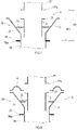
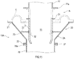
- FIG. 11 shows an expansion joint 10A according to a first variant and is an end view of the expansion joint 10A cut along a plane including the central axis of the expansion joint 10A.
- the expansion joint 10A of FIG. 11 includes an outer tube 2A, which is devoid of the baffle plate 24.
- the middle flange 33 of the inner tube 3 is in contact with the inner circumferential surface of the barrel 23 of the outer tube 2A.
- the inner tube 3 is supported by the outer tube 2A and restricted from moving downward relative to the outer tube 2A.
- the baffle plate 24 the likelihood of contact between the transferred material and the closure 4 can be reduced since the closure 4 is maximally far from a point where the transferred material enters the gap between the inner tube 3 and the outer tube 2A.
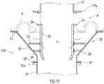
- FIG. 12 shows an expansion joint 10B according to a second variant and is an end view of the expansion joint 10B cut along a plane including the central axis of the expansion joint 10B.
- the expansion joint 10B of the FIG. 12 includes an outer tube 2A, which is devoid of the baffle plate 24.
- the expansion joint 10B includes an inner tube 3A including a lower flange 34 located below the middle flange 33.
- the lower flange 34 protrudes radially outward from the outer circumferential surface of the barrel 32.
- the outer diameter of the lower flange 34 is smaller than the outer diameter D33 of the middle flange 33.
- the lower flange 34 of the inner tube 3 A is in contact with the inner circumferential surface of the barrel 23 of the outer tube 2A.
- the inner tube 3A is supported by the outer tube 2A and restricted from moving downward relative to the outer tube 2A.
- the baffle plate 24 the likelihood of contact between the transferred material and the closure 4 can be reduced since the lower flange 34 serves to prevent the transferred material from entering the gap between the inner tube 3A and the outer tube 2A.
- the expansion joint according to the present disclosure is not limited to the embodiments described above, and can be widely used as an expansion unit included in a piping system through which a powdery or granular material is transferred, in particular as an expansion unit that is located at a point of connection of pipes in a region where the material is transferred by gravity and that absorbs displacement between the connected pipes.
Landscapes
- Engineering & Computer Science (AREA)
- General Engineering & Computer Science (AREA)
- Mechanical Engineering (AREA)
- Food Science & Technology (AREA)
- Joints Allowing Movement (AREA)
- Incineration Of Waste (AREA)
- Gasification And Melting Of Waste (AREA)
- Rigid Pipes And Flexible Pipes (AREA)
Abstract
Description
- The present disclosure relates to expansion joints in piping systems through which powdery or granular materials are transferred and in particular to an expansion joint that is located at a point of connection of pipes in a region where a powdery or granular material is transferred by gravity and that absorbs displacement between the connected pipes. The present disclosure also relates to incineration ash treatment equipment including the expansion pipe.
- Conventionally, there is known an expansion joint included in equipment for treatment of powdery or granular materials and used at a connection point where displacement between connected parts occurs, such as at a point of connection between a vibrator and a pipe. The present applicant has proposed such a kind of expansion joint in Patent Literature 1.
- The expansion joint of Patent Literature 1 includes an outer tube, an inner tube located inside the outer tube, and an elastic closure (bellows) closing a gap between the upstream ends of the inner and outer tubes. The downstream end of the outer tube is connected to a downstream pipe, and the upstream end of the inner tube is connected to an upstream pipe. The upstream ends of the inner and outer tubes are located at substantially the same height. In the expansion joint of Patent Literature 1, the downstream end of the inner tube and the closure are far enough from each other to prevent contact between the closure and a hot transferred material getting in between the inner and outer tubes.
- PTL 1:
Japanese Laid-Open Patent Application Publication No. 2018-173117 - Expansion joints are inserted between upstream and downstream pipes placed beforehand. Expansion joints are heavy, and may be located at great heights or in narrow places. With the use of the expansion joint of Patent Literature 1 in such a situation, the expansion joint mounting work including connecting the inner tube to the upstream pipe and attaching the closure could be cumbersome because the upstream end of the outer tube, the upstream end of the inner tube, and the downstream end of the upstream pipe are located at substantially the same height.
- The present disclosure has been made in view of the above circumstances, and an object of the present disclosure is to propose an expansion joint in which the downstream end of an inner tube and a closure are far enough from each other and which can easily be mounted and removed.
- An expansion joint according to one aspect of the present disclosure is an expansion joint that absorbs displacement occurring at a point of connection between upstream and downstream pipes through which a powdery and/or granular material is transferred by gravity, the expansion joint including:
- an outer tube including opposite first and second ends and extending from the first end to the second end in an axial direction of the expansion joint, the outer tube further including a first flange and a second flange, the first flange being located at the first end, the second flange being located at the second end and connectable to the downstream pipe;
- an inner tube including opposite third and fourth ends and extending from the third end to the fourth end in the axial direction, the inner tube being located inside the outer tube and further including a third flange and a middle flange, the third flange being located at the third end and connectable to the upstream pipe, the middle flange being located at a middle portion between the third and fourth ends; and
- a closure including an outer peripheral portion connected to the first flange, an inner peripheral portion connected to the middle flange, and an elastic portion connecting the outer peripheral portion to the inner peripheral portion, wherein
- the first end is spaced from the third end in the axial direction and located between the third and fourth ends in the axial direction.
- Incineration ash treatment equipment according to one aspect of the present disclosure includes: a vibrator that treats incineration ash; a pipe that delivers the incineration ash to the vibrator; and the expansion joint as defined above, the expansion joint being located between an outlet of the pipe and an inlet of the vibrator.
- In the expansion joint and incineration ash treatment equipment configured as described above, the middle flange, to which the closure is attached, is spaced from the fourth end (i.e., downstream end) of the inner tube in the axial direction. Thus, the fourth end of the inner tube and the closure can be spaced a distance corresponding to the distance between the fourth end and middle flange of the inner tube in the axial direction. This can reduce the likelihood that the transferred material entering the gap between the inner tube and the outer tube from the fourth end of the inner tube comes into contact with the
closure 4. - In the expansion joint and incineration ash treatment equipment configured as described above, the first flange located at the first end of the outer tube and the third flange located at the third end of the inner tube are spaced from each other in the axial direction. The space between the first flange and the third flange in the axial direction can be used as a workspace for connection (or disconnection) of the third flange and the upstream pipe. Thus, connection and disconnection of the expansion joint and the upstream pipe can easily be performed.
- In the expansion joint and incineration ash treatment equipment configured as described above, the third end of the inner tube connected to the upstream pipe and the first end of the outer tube are spaced from each other in the axial direction. Thus, the dimension of the outer tube in the axial direction is smaller than the vertical dimension of a mounting region extending between the upstream pipe and the downstream pipe. As such, the outer tube with the inner tube inserted therein can easily be carried into the mounting region. After the inner tube and the outer tube are placed in the mounting region, the closure can be carried into the mounting region by utilizing a gap between the upstream pipe and the outer tube. Additionally, the space between the third flange and the middle flange in the axial direction can be used as a workspace for attachment (or detachment) of the closure. Thus, attachment and detachment of the closure are easy.
- The present disclosure can propose an expansion joint in which the downstream end of an inner tube and a closure are far enough from each other and which can easily be mounted and removed.
-
-
FIG. 1 shows a schematic configuration of incineration ash treatment equipment including an expansion joint according to an exemplary embodiment of the present disclosure. -
FIG. 2 shows the expansion joint according to the exemplary embodiment of the present disclosure and is an end view of the expansion joint cut along a plane including the central axis of the expansion joint. -
FIG. 3 shows an outer tube as viewed in the axial direction. -
FIG. 4 shows an inner tube as viewed in the axial direction. -
FIG. 5 shows a closure as viewed in the axial direction. -
FIG. 6 is a view taken along the arrow VI-VI ofFIG. 2 . -
FIG. 7 illustrates how to mount the expansion joint. -
FIG. 8 illustrates how to mount the expansion joint. -
FIG. 9 illustrates how to mount the expansion joint. -
FIG. 10 illustrates how to mount the expansion joint. -
FIG. 11 shows an expansion joint according to a first variant and is an end view of the expansion joint cut along a plane including the central axis of the expansion joint. -
FIG. 12 shows an expansion joint according to a second variant and is an end view of the expansion joint cut along a plane including the central axis of the expansion joint. - Hereinafter, exemplary embodiments of the present disclosure will be described with reference to the drawings.
FIG. 1 shows a schematic configuration of incinerationash treatment equipment 7 including anexpansion joint 10 according to an exemplary embodiment of the present disclosure. The incinerationash treatment equipment 7 is adapted to finely grind incineration ash generated, for example, in a coal-fired boiler or garbage incinerator. - The incineration
ash treatment equipment 7 ofFIG. 1 includes agrinder 75 that finely grindsincineration ash 70, aconveyor 74 that transfers theincineration ash 70 to thegrinder 75, and ahopper 76 that receives theincineration ash 70 ground by thegrinder 75. A vibrating mill can be used as thegrinder 75. In a typical vibrating mill, a grinding medium and a material to be ground collides with each other in a rapidly vibrating drum, and thus the material is finely ground. - The
conveyor 74 and thegrinder 75 are connected by a piping system through which theincineration ash 70 in the form of grains or aggregates is transferred. The piping system includes a vibratingpipe 78 coupled to the inlet of thegrinder 75, afixed pipe 77 located upstream of the vibratingpipe 78, and anexpansion joint 10 connecting thefixed pipe 77 to the vibratingpipe 78. The terms "upstream" and "downstream", as used in the specification and the appended claims, respectively refer to upstream and downstream in the direction of flow of the material (incineration ash 70) transferred through the piping system. Thefixed pipe 77 is an "upstream pipe" for theexpansion joint 10, and the vibratingpipe 78 is a "downstream pipe" for theexpansion joint 10. - The
fixed pipe 77 is fixed relative to a structure including a device upstream of the grinder 75 (the device is, for example, theconveyor 74 or an unshown device used for another coal treatment process). The vibratingpipe 78 vibrates in conjunction with vibration of the drum of thegrinder 75. Thus, displacement occurs at a point of connection between thefixed pipe 77 and the vibratingpipe 78 due to the vibration of the vibratingpipe 78. Theexpansion joint 10 absorbs the displacement occurring at the point of connection between the fixedpipe 77 and the vibratingpipe 78. Theexpansion joint 10 according to the present disclosure is applicable also in the case where both the fixedpipe 77 and the vibratingpipe 78 are movable. - Hereinafter, the
expansion joint 10 will be described in detail.FIG. 2 shows theexpansion joint 10 according to an exemplary embodiment of the present disclosure and is an end view of theexpansion joint 10 cut along a plane including the central axis of theexpansion joint 10. Theexpansion joint 10 is generally shaped as a solid of revolution. The direction in which the axis of revolution extends is referred to as the "axial direction X" of theexpansion joint 10, and the axis of revolution is referred to as the "central axis" of theexpansion joint 10. Theexpansion joint 10 is mounted in a space between the fixedpipe 77 and the vibratingpipe 78 in the up-down direction. The space between the fixedpipe 77 and the vibratingpipe 78 in the up-down direction will be referred to as a "mounting region A" hereinafter. When the vibratingpipe 78 is at rest, a straight line drawn between the center of the opening of the fixedpipe 77 and the center of the opening of the vibratingpipe 78 is parallel to the axial direction X of theexpansion joint 10. - The
expansion joint 10 ofFIG. 2 includes anouter tube 2, aninner tube 3 located inside theouter tube 2, and aclosure 4 closing a gap between theouter tube 2 and theinner tube 3. The inner circumference of theinner tube 3 defines atransfer path 11 along which the transferred material (e.g., the incineration ash 70) flows through theexpansion joint 10. -
FIG. 3 shows theouter tube 2 as viewed in the axial direction X. As shown inFIGS. 2 and3 , theouter tube 2 is a metallic tubular body extending from its upstream end (first end) to its downstream end (second end) in the axial direction X. Theouter tube 2 includes afirst flange 21 located at the upstream end of theouter tube 2, asecond flange 22 located at the downstream end of theouter tube 2, abarrel 23 connecting thefirst flange 21 to thesecond flange 22, and abaffle plate 24 located on the inner circumference of thebarrel 23. Each of the first andsecond flanges - The
second flange 22 is connected to aninlet flange 78a located at the upstream end of the vibratingpipe 78. Between thesecond flange 22 and theinlet flange 78a there is alower gasket 37 that provides hermeticity. Theouter tube 2 vibrates in conjunction with vibration of the vibratingpipe 78. - The inner diameter D21 of the
first flange 21 is greater than the inner diameter D22 of thesecond flange 22. Thebarrel 23 is tapered downward to smoothly connect the first andsecond flanges outer tube 2 structured as described above can ensure a range over which theouter tube 2 is displaceable relative to theinner tube 3 in a direction perpendicular to the axial direction X and at the same time allow for quick movement or transfer of the material from theouter tube 2 to the vibratingpipe 78. - The
baffle plate 24 serves to prevent the transferred material accumulated in thetransfer path 11 of the expansion joint 10 from entering the gap between theouter tube 2 and theinner tube 3. Thebaffle plate 24 is shaped as an annular disc and located at approximately the center of thebarrel 23 in the axial direction X. The inner diameter D24a of thebaffle plate 24 is greater than the inner diameter D22 of thesecond flange 22. The outer diameter D24b of thebaffle plate 24 is smaller than the inner diameter D21 of thefirst flange 21. The outer periphery of thebaffle plate 24 is welded to the inner circumferential surface of thebarrel 23. -
FIG. 4 shows theinner tube 3 as viewed in the axial direction X. As shown inFIGS. 2 and4 , theinner tube 3 is a metallic tubular body extending from its upstream end (third end) to its downstream end (fourth end) in the axial direction X. Theinner tube 3 includes athird flange 31 located at the upstream end of theinner tube 3, abarrel 32 extending downward from thethird flange 31, and amiddle flange 33 located at a middle portion of thebarrel 32 in the axial direction X. Themiddle flange 33 includes circumferentially arranged insertion holes. Bolts are inserted into the insertion holes. - The
third flange 31 is connected to anoutlet flange 77a located at the downstream end of the fixedpipe 77. The outer diameter D31 of thethird flange 31 is smaller than the outer diameter of theoutlet flange 77a. Thethird flange 31 is placed betweenretainers 25 and theoutlet flange 77a, and theretainers 25,outlet flange 77a, andthird flange 31 are fastened together by bolts inserted through theretainers 25 and theoutlet flange 77a. The retainers 25 (the number of which is, for example, four) are arranged along the outer periphery of thethird flange 31. Each of theretainers 25 is shaped as a segment of a ring, and theretainers 25 form the ring together. Each of theretainers 25 includes a cut at its upper inner periphery, and thethird flange 31 is fitted in the cut. Thus, thethird flange 31 of theinner tube 3 is restricted from moving relative to theoutlet flange 77a of the fixedpipe 77 in the radial and up-down directions in the event that the point of connection between the fixedpipe 77 and theinner tube 3 is subjected to vibration. Each of theretainers 25 includes at least oneinsertion hole 25a for insertion of a bolt. Between theretainers 25 and theoutlet flange 77a there is anupper gasket 36 that provides hermeticity. - The
middle flange 33 protrudes radially outward from the outer circumferential surface of thebarrel 32. The outer diameter D33 of themiddle flange 33 is greater than the inner diameter D24a of thebaffle plate 24 and smaller than the outer diameter D24b of thebaffle plate 24. To improve the handleability of theinner tube 3, the outer diameter D31 of thethird flange 31 is desirably smaller than the outer diameter D33 of themiddle flange 33. -
FIG. 5 shows theclosure 4 as viewed in the axial direction X. As shown inFIGS. 2 and5 , theclosure 4 is shaped as an annular disc. Theclosure 4 includes an innerperipheral portion 41, an outerperipheral portion 42, and anelastic portion 43 located between the innerperipheral portion 41 and the outerperipheral portion 42. Each of the inner and outerperipheral portions - The inner diameter D41 of the
closure 4 is greater than the outer diameter D32 of thebarrel 32 of the inner tube 3 (i.e., the inner diameter of the middle flange 33) and smaller than the outer diameter D33 of themiddle flange 33. The outer diameter D42 of theclosure 4 is greater than the inner diameter D21 of thefirst flange 21 of theouter tube 2. -
FIG. 6 is a view taken along the arrow VI-VI ofFIG. 2 . As shown inFIGS. 2 and6 , the innerperipheral portion 41 of theclosure 4 is connected to themiddle flange 33 of theinner tube 3. The innerperipheral portion 41 is placed between themiddle flange 33 of theinner tube 3 andretainers 28, and theretainers 28, innerperipheral portion 41, andmiddle flange 33 are fastened together by bolts inserted through theretainers 28, innerperipheral portion 41, andmiddle flange 33. The retainers 28 (the number of which is, for example, four) are arranged in a ring along the innerperipheral portion 41. Each of theretainers 28 is shaped as a segment of a ring, and theretainers 28 form the ring together. - The outer
peripheral portion 42 of theclosure 4 is connected to thefirst flange 21 of theouter tube 2. The outerperipheral portion 42 is placed between thefirst flange 21 of theouter tube 2 andretainers 26, and theretainers 26, outerperipheral portion 42, andfirst flange 21 are fastened together by bolts inserted through theretainers 26, outerperipheral portion 42, andfirst flange 21. The retainers 26 (the number of which is, for example, four) are arranged in a ring along the outerperipheral portion 42. Each of theretainers 26 is shaped as a segment of a ring, and theretainers 26 form the ring together. - The
elastic portion 43 is expanded or contracted to absorb displacement of the outerperipheral portion 42 relative to the innerperipheral portion 41 in the axial direction X and the radial direction. Theelastic portion 43 shown inFIG. 2 is made of rubber, resin, or fabric and includes one or more corrugations arranged in the radial direction. Theelastic portion 43 is not limited to being corrugated. For example, theelastic portion 43 of theclosure 4 may be shaped as a flat sheet insofar as theelastic portion 43 is made of elastic rubber or resin. In the case where the material to be transferred is hot, a heat-resistant material is desirably used for theelastic portion 43. - As shown in
FIG. 2 , for theexpansion joint 10 configured as described above, the dimension of theouter tube 2 in the axial direction X is referred to as "outer tube height H2", the dimension of theinner tube 3 in the axial direction X is referred to as "inner tube height H3", the dimension of theinner tube 3 from its upstream end to themiddle flange 33 in the axial direction X is referred to as "protrusion height H3a", the dimension of theclosure 4 in the axial direction X is referred to as "closure height H4", and the dimension of the mounting region A in a direction parallel to the axial direction X is referred to as "mounting region height HO". - The outer tube height H2 is smaller than the mounting region height H0. The sum of the outer tube height H2 and the closure height H4 is desirably smaller than the mounting region height H0.
- The inner tube height H3 is smaller than the mounting region height H0. The sum of the inner tube height H3 and the closure height H4 is desirably smaller than the mounting region height H0. The protrusion height H3a is desirably greater than the closure height H4.
- The sum of the outer tube height H2, the protrusion height H3a, the thickness of the
upper gasket 36, and the thickness of thelower gasket 37 is substantially equal to the mounting region height H0. - The following describes how to mount the
expansion joint 10.FIGS. 7 to 10 illustrate how to mount theexpansion joint 10. - First, as shown in
FIG. 7 , theouter tube 2 and theinner tube 3 are combined into anassembly 20. To construct theassembly 20, theinner tube 3 is inserted into theouter tube 2 from above. In theassembly 20, the upper surface of thebaffle plate 24 of theouter tube 2 is in contact with the lower surface of themiddle flange 33 of theinner tube 3. Thus, theinner tube 3 is stably supported by theouter tube 2 and restricted from moving downward relative to theouter tube 2. - The
assembly 20 is placed into the mounting region A, and thesecond flange 22 of theouter tube 2 is placed onto theinlet flange 78a of the vibratingpipe 78. The dimension of theassembly 20 in the axial direction X is referred to as "assembly height H20". The assembly height H20 is smaller than the mounting region height H0 by approximately an extension amount H24 corresponding to the length from thebaffle plate 24 to thefirst flange 21 in the axial direction X. As the assembly height H20 is smaller than the mounting region height H0, theassembly 20 can easily be brought into the mounting region A in a direction perpendicular to the axial direction X. - Next, as shown in
FIG. 8 , theclosure 4 is placed into the mounting region A. The sum of the assembly height H20 and the closure height H4 is desirably smaller than the mounting region height H0 so that theclosure 4 can easily be brought into the mounting region A in a direction perpendicular to the axial direction X. As theclosure 4 is elastically deformable, the size of the gap between the fixedpipe 77 and theassembly 20 may be slightly smaller than the closure height H4. - Subsequently, as shown in
FIG. 9 , theinner tube 3 is raised a distance equal to the extension amount H24 relative to theouter tube 2 to bring thethird flange 31 of theinner tube 3 into contact with theoutlet flange 77a of the fixedpipe 77. As a result, the location of themiddle flange 33 of theinner tube 3 in the axial direction X becomes approximately the same as the location of thefirst flange 21 of theouter tube 2 in the axial direction X. - Afterwards, as shown in
FIG. 10 , theoutlet flange 77a of the fixedpipe 77 and thethird flange 31 are fastened by bolts. Theinlet flange 78a of the vibratingpipe 78 and thesecond flange 22 are fastened by bolts, the innerperipheral portion 41 of theclosure 4 and themiddle flange 33 are fastened by bolts, and the outerperipheral portion 42 of theclosure 4 and thefirst flange 21 of theouter tube 2 are fastened by bolts. The bolt fastening may be performed at any time during the mounting work. - The
expansion joint 10 can be removed by a reverse procedure to the mounting of theexpansion joint 10. That is, theexpansion joint 10 can be removed from the mounting region A by unfastening the bolts, lowering theinner tube 3 toward theouter tube 2, removing theclosure 4 from the mounting region A, and removing theassembly 20 from the mounting region A. - As described above, incineration
ash treatment equipment 7 according to an exemplary embodiment includes agrinder 75 serving as a vibrator that treats incineration ash, a pipe (a fixedpipe 77 serving as an upstream pipe) that delivers the incineration ash to thegrinder 75, and anexpansion joint 10 located between an outlet of the pipe and an inlet of the grinder 75 (or a vibratingpipe 78 serving as a downstream pipe). Theexpansion joint 10 absorbs displacement occurring at a point of connection between the upstream anddownstream pipes expansion joint 10 includes anouter tube 2, aninner tube 3 located inside theouter tube 2, and aclosure 4 closing a gap between theouter tube 2 and theinner tube 3. Theouter tube 2 includes opposite first and second ends (upstream and downstream ends) and extends from the first end to the second end in an axial direction X of theexpansion joint 10. Theouter tube 2 further includes afirst flange 21 and asecond flange 22, thefirst flange 21 being located at the first end, thesecond flange 22 being located at the second end and connectable to the downstream pipe. Theinner tube 3 includes opposite third and fourth ends (upstream and downstream ends) and extends from the third end to the fourth end in the axial direction X. Theinner tube 3 further includes athird flange 31 and amiddle flange 33, thethird flange 31 being located at the third end and connectable to the upstream pipe, themiddle flange 33 being located at a middle portion between the third and fourth ends. Theclosure 4 includes an outerperipheral portion 42 connected to thefirst flange 21, an innerperipheral portion 41 connected to themiddle flange 33, and anelastic portion 43 connecting the outerperipheral portion 42 to the innerperipheral portion 41. - In the
expansion joint 10 according to the above embodiment, thefirst flange 21 of theouter tube 2 secured to thedownstream pipe 78 and themiddle flange 33 of theinner tube 3 secured to theupstream pipe 77 are at the same location in the axial direction X. The statement that "thefirst flange 21 and themiddle flange 33 are at the same location in the axial direction X" is intended to include not only the case where the location of thefirst flange 21 in the axial direction X and the location of themiddle flange 33 in the axial direction X are exactly the same, but also the case where the distance between the locations of thefirst flange 21 and themiddle flange 33 in the axial direction X is equal to or below a threshold. For example, the threshold is equal to, and desirably smaller than, the dimension of theclosure 4 in the axial direction X (i.e., the closure height H4). - The present disclosure is not limited to the
expansion joint 10 in which thefirst flange 21 of theouter tube 2 secured to thedownstream pipe 78 and themiddle flange 33 of theinner tube 3 secured to theupstream pipe 77 are at the same location in the axial direction X. In theexpansion joint 10, the first end (upstream end) of theouter tube 2 may be spaced from the third end (upstream end) of theinner tube 3 in the axial direction X and located between the third end and the fourth end (downstream end) of theinner tube 3 in the axial direction X. - In the
expansion joint 10 and incinerationash treatment equipment 7 configured as described above, themiddle flange 33, to which theclosure 4 is attached, is spaced from the fourth end of theinner tube 3 in the axial direction X. Thus, the downstream end of theinner tube 3 and theclosure 4 can be spaced a distance corresponding to the distance between the downstream end andmiddle flange 33 of theinner tube 3 in the axial direction X. This can reduce the likelihood that the transferred material entering the gap between theinner tube 3 and theouter tube 2 from the downstream end of theinner tube 3 comes into contact with theclosure 4. - In the
expansion joint 10 and incinerationash treatment equipment 7 configured as described above, thefirst flange 21 located at the first end of theouter tube 2 and thethird flange 31 located at the third end of theinner tube 3 and connected to theupstream pipe 77 are spaced from each other in the axial direction X. The space between thefirst flange 21 and thethird flange 31 in the axial direction X can be used as a workspace for connection (or disconnection) of thethird flange 31 and theupstream pipe 77. Despite thefirst flange 21 being located radially outside thethird flange 31, the work of connecting thethird flange 31 and theupstream pipe 77 is not disturbed by thefirst flange 21. Thus, connection and disconnection of theexpansion joint 10 and theupstream pipe 77 can easily be performed. - In the
expansion joint 10 and incinerationash treatment equipment 7 configured as described above, the third end (upstream end) of theinner tube 3 connected to theupstream pipe 77 and the first end (upstream end) of theouter tube 2 connected to thedownstream pipe 78 are spaced from each other in the axial direction X. Thus, the dimension of theouter tube 2 in the axial direction X (outer tube height H2) is smaller than the vertical dimension of the mounting region A extending between theupstream pipe 77 and the downstream pipe 78 (mounting region height H0). As such, theouter tube 2 with theinner tube 3 inserted therein (i.e., the assembly 20) can easily be carried into the mounting region A. After theassembly 20 constructed of theinner tube 3 and theouter tube 2 is placed in the mounting region A, theclosure 4 can be carried into the mounting region A by utilizing a gap extending downward from theupstream pipe 77 and having a size corresponding to the extension amount H24. Additionally, the space between thethird flange 31 connected to theupstream pipe 77 and themiddle flange 33 can be used as a workspace for attachment (or detachment) of theclosure 4. Thus, attachment and detachment of theclosure 4 are easy, and this is advantageous not only in mounting/removing work but also in maintenance work in which only theclosure 4 is replaced by a new one. - In the
expansion joint 10 and incinerationash treatment equipment 7 according to the above embodiment, the downstream end of theinner tube 3 and theclosure 4 are far enough from each other to avoid contact between the transferred material and theclosure 4. Theexpansion joint 10 serves the same function as the conventional expansion joint disclosed in Patent Literature 1 and is easier to mount and remove than the conventional expansion joint. - In the
expansion joint 10 according to the above embodiment, the outer diameter D33 of themiddle flange 33 is greater than the inner diameter D22 of thesecond flange 22 and smaller than the inner diameter D21 of thefirst flange 21. - Thus, the
inner tube 3 is stably supported by theouter tube 2 in theassembly 20 constructed by inserting theinner tube 3 into theouter tube 2. - In the
expansion joint 10 according to the above embodiment, theouter tube 2 includes abaffle plate 24 shaped as an annular disc that projects radially from an inner circumferential surface of theouter tube 2. Although thebaffle plate 24 according to the above embodiment is shaped as an annular disc that is circumferentially continuous, thebaffle plate 24 may be shaped as an annular disc that is circumferentially discontinuous. - The
baffle plate 24 serves to prevent the transferred material from reaching theclosure 4 through the gap between theouter tube 2 and theinner tube 3. This can reduce the likelihood of contact between the transferred material and theclosure 4. - In the
above expansion joint 10, thebaffle plate 24 is located between themiddle flange 33 and thesecond flange 22 in the axial direction X, and the outer diameter of themiddle flange 33 is greater than the inner diameter of thebaffle plate 24 and smaller than the outer diameter of thebaffle plate 24. - Thus, in the
assembly 20 constructed by inserting theinner tube 3 into theouter tube 2, themiddle flange 33 is in contact with, and supported by, thebaffle plate 24. As such, theinner tube 3 is stably supported by theouter tube 2. - The
expansion joint 10 according to the above embodiment further includesfirst retainers 25 arranged circumferentially along an outer periphery of thethird flange 31 to hold thethird flange 31 between theupstream pipe 77 and the first retainers. Each of thefirst retainers 25 includes at least oneinsertion hole 25a for insertion of a bolt. - The insertion holes through which bolts are inserted to connect the
third flange 31 to theoutlet flange 77a of theupstream pipe 77 are included in thefirst retainers 25, rather than thethird flange 31. This eliminates the need to adjust the rotational position of theinner tube 3 to align theoutlet flange 77a and thethird flange 31. Additionally, each of thefirst retainer 25 is not shaped as a circular ring but a segment of a circular ring, and thus thefirst retainers 25 can be arranged around thethird flange 31 without having to pass theinner tube 3 through the central opening of the circular ring formed by thefirst retainers 25. As such, mounting and removal of theexpansion joint 10 are simplified. - The
expansion joint 10 according to the above embodiment further includessecond retainers 28 arranged circumferentially along the innerperipheral portion 41 of theclosure 4 to hold the innerperipheral portion 41 between themiddle flange 33 and thesecond retainers 28. Theexpansion joint 10 according to the above embodiment further includesthird retainers 26 arranged circumferentially along the outerperipheral portion 42 of theclosure 4 to hold the outerperipheral portion 42 between thefirst flange 21 and thethird retainers 26. - Each of the
second retainers 28 and thethird retainers 26 is not shaped as a circular ring but a segment of a circular ring. Thus, thesecond retainers 28 can be arranged along the innerperipheral portion 41 of theclosure 4 without having to pass theouter tube 2,inner tube 3, andclosure 4 through the central opening of the circular ring formed by thesecond retainers 28. Thethird retainers 26 can be arranged along the outerperipheral portion 42 of theclosure 4 without having to pass theouter tube 2,inner tube 3, andclosure 4 through the central opening of the circular ring formed by thethird retainers 26. - Although the foregoing has described a preferred embodiment of the present disclosure, the scope of the present disclosure embraces modifications made to the details of the structure and/or function of the above embodiment without departing from the gist of the present disclosure.
- For example, although the
outer tube 2 of theexpansion joint 10 according to the above embodiment includes thebaffle plate 24, thebaffle plate 24 is not essential and may be omitted. -
FIG. 11 shows an expansion joint 10A according to a first variant and is an end view of theexpansion joint 10A cut along a plane including the central axis of theexpansion joint 10A. The expansion joint 10A ofFIG. 11 includes anouter tube 2A, which is devoid of thebaffle plate 24. In theassembly 20 constructed of theouter tube 2A and theinner tube 3, themiddle flange 33 of theinner tube 3 is in contact with the inner circumferential surface of thebarrel 23 of theouter tube 2A. Thus, theinner tube 3 is supported by theouter tube 2A and restricted from moving downward relative to theouter tube 2A. Despite the absence of thebaffle plate 24, the likelihood of contact between the transferred material and theclosure 4 can be reduced since theclosure 4 is maximally far from a point where the transferred material enters the gap between theinner tube 3 and theouter tube 2A. -
FIG. 12 shows anexpansion joint 10B according to a second variant and is an end view of the expansion joint 10B cut along a plane including the central axis of theexpansion joint 10B. The expansion joint 10B of theFIG. 12 includes anouter tube 2A, which is devoid of thebaffle plate 24. Theexpansion joint 10B includes aninner tube 3A including alower flange 34 located below themiddle flange 33. Thelower flange 34 protrudes radially outward from the outer circumferential surface of thebarrel 32. The outer diameter of thelower flange 34 is smaller than the outer diameter D33 of themiddle flange 33. In theassembly 20 constructed of theouter tube 2A and theinner tube 3A, thelower flange 34 of theinner tube 3 A is in contact with the inner circumferential surface of thebarrel 23 of theouter tube 2A. Thus, theinner tube 3A is supported by theouter tube 2A and restricted from moving downward relative to theouter tube 2A. Despite the absence of thebaffle plate 24, the likelihood of contact between the transferred material and theclosure 4 can be reduced since thelower flange 34 serves to prevent the transferred material from entering the gap between theinner tube 3A and theouter tube 2A. - The expansion joint according to the present disclosure is not limited to the embodiments described above, and can be widely used as an expansion unit included in a piping system through which a powdery or granular material is transferred, in particular as an expansion unit that is located at a point of connection of pipes in a region where the material is transferred by gravity and that absorbs displacement between the connected pipes.
-
- 2: outer tube
- 3: inner tube
- 4: closure
- 7: incineration ash treatment equipment
- 10: expansion joint
- 21: first flange
- 22: second flange
- 24: baffle plate
- 25, 26, 28: retainer
- 31: third flange
- 33: middle flange
- 41: inner peripheral portion
- 42: outer peripheral portion
- 43: elastic portion
- 70: incineration ash
- 77: fixed pipe (upstream pipe)
- 78: vibrating pipe (downstream pipe)
Claims (9)
- An expansion joint that absorbs displacement occurring at a point of connection between upstream and downstream pipes through which a powdery and/or granular material is transferred by gravity, the expansion joint comprising:an outer tube including opposite first and second ends and extending from the first end to the second end in an axial direction of the expansion joint, the outer tube further including a first flange and a second flange, the first flange being located at the first end, the second flange being located at the second end and connectable to the downstream pipe;an inner tube including opposite third and fourth ends and extending from the third end to the fourth end in the axial direction, the inner tube being located inside the outer tube and further including a third flange and a middle flange, the third flange being located at the third end and connectable to the upstream pipe, the middle flange being located at a middle portion between the third and fourth ends; anda closure including an outer peripheral portion connected to the first flange, an inner peripheral portion connected to the middle flange, and an elastic portion connecting the outer peripheral portion to the inner peripheral portion, whereinthe first end is spaced from the third end in the axial direction and located between the third and fourth ends in the axial direction.
- The expansion joint according to claim 1, wherein the first flange and the middle flange are at the same location in the axial direction.
- The expansion joint according to claim 1 or 2, wherein an outer diameter of the middle flange is greater than an inner diameter of the second flange and smaller than an inner diameter of the first flange.
- The expansion joint according to any one of claims 1 to 3, wherein the outer tube includes a baffle plate shaped as an annular disc that projects radially from an inner circumferential surface of the outer tube or shaped as an annular disc that is circumferentially discontinuous.
- The expansion joint according to claim 4, whereinthe baffle plate is located between the middle flange and the second flange in the axial direction, andan outer diameter of the middle flange is greater than an inner diameter of the baffle plate and smaller than an outer diameter of the baffle plate.
- The expansion joint according to any one of claims 1 to 5, further comprising first retainers arranged circumferentially along an outer periphery of the third flange to hold the third flange between the upstream pipe and the first retainers, wherein
each of the first retainers includes at least one insertion hole for insertion of a bolt. - The expansion joint according to any one of claims 1 to 6, further comprising second retainers arranged circumferentially along the inner peripheral portion of the closure to hold the inner peripheral portion between the middle flange and the second retainers.
- The expansion joint according to any one of claims 1 to 7, further comprising third retainers arranged circumferentially along the outer peripheral portion of the closure to hold the outer peripheral portion between the first flange and the third retainers.
- Incineration ash treatment equipment comprising:a vibrator that treats incineration ash;a pipe that delivers the incineration ash to the vibrator; andthe expansion joint according to any one of claims 1 to 8, the expansion joint being located between an outlet of the pipe and an inlet of the vibrator.
Applications Claiming Priority (2)
| Application Number | Priority Date | Filing Date | Title |
|---|---|---|---|
| JP2020045284A JP7402086B2 (en) | 2020-03-16 | 2020-03-16 | Expansion pipe joints and incineration ash processing equipment |
| PCT/JP2021/009751 WO2021187303A1 (en) | 2020-03-16 | 2021-03-11 | Expansion pipe joint and incineration ash treatment facility |
Publications (3)
| Publication Number | Publication Date |
|---|---|
| EP4123207A1 true EP4123207A1 (en) | 2023-01-25 |
| EP4123207A4 EP4123207A4 (en) | 2024-03-27 |
| EP4123207B1 EP4123207B1 (en) | 2025-06-18 |
Family
ID=77771274
Family Applications (1)
| Application Number | Title | Priority Date | Filing Date |
|---|---|---|---|
| EP21770934.4A Active EP4123207B1 (en) | 2020-03-16 | 2021-03-11 | Expansion joint and incineration ash treatment equipment |
Country Status (5)
| Country | Link |
|---|---|
| US (1) | US12264760B2 (en) |
| EP (1) | EP4123207B1 (en) |
| JP (1) | JP7402086B2 (en) |
| TW (1) | TWI767610B (en) |
| WO (1) | WO2021187303A1 (en) |
Family Cites Families (17)
| Publication number | Priority date | Publication date | Assignee | Title |
|---|---|---|---|---|
| US686598A (en) * | 1901-07-02 | 1901-11-12 | Quimby N Evans | Expansion-joint for pipes. |
| US1076738A (en) * | 1912-10-29 | 1913-10-28 | Edward F Berry | Dredging device (coupling.) |
| GB1130911A (en) * | 1965-03-09 | 1968-10-16 | English Electric Co Ltd | Expansion joints |
| NL7906355A (en) * | 1978-08-24 | 1980-02-26 | Bridgestone Tire Co Ltd | FLEXIBLE PIPE COUPLING. |
| US4251354A (en) * | 1979-12-28 | 1981-02-17 | Rotex, Inc. | Screening machine |
| GB2083152B (en) * | 1980-06-24 | 1984-01-11 | Grovag Grossventiltech | Seals for ducts |
| JPS6060394A (en) * | 1983-09-14 | 1985-04-06 | バブコツク日立株式会社 | Vibration absorbing connector |
| JPH03153987A (en) * | 1989-11-10 | 1991-07-01 | Nkk Corp | Expansion joint |
| US5259511A (en) * | 1991-09-27 | 1993-11-09 | Rotex, Inc. | Sliding conduit connector for screening machine |
| US5443290A (en) * | 1993-12-03 | 1995-08-22 | Mid-Atlantic Technical Services Incorporated | Floating ring expansion joint liner seal |
| US5887726A (en) * | 1996-07-30 | 1999-03-30 | Rotex, Inc. | Coupling for connecting feed spout to screening machine |
| US8646534B2 (en) * | 2011-05-23 | 2014-02-11 | Richard R. Magden | Well head containment fitting device |
| CN202203966U (en) * | 2011-07-26 | 2012-04-25 | 成都万基电力设备制造有限公司 | Dedicated three-dimensional expansion joint of slag cooler |
| CN104976462B (en) * | 2015-07-08 | 2017-06-13 | 河南昌茂供水设备有限公司 | External pressure elastomer connector |
| JP6863798B2 (en) | 2017-03-31 | 2021-04-21 | 川崎重工業株式会社 | Expansion joints and incineration ash treatment equipment |
| CN108131524A (en) * | 2017-12-30 | 2018-06-08 | 江苏恒丰波纹管有限公司 | Three-dimensional ball joint compensator with guide ring |
| KR101970172B1 (en) * | 2019-01-18 | 2019-04-18 | 고경태 | Earthquake proof slip joint for piping |
-
2020
- 2020-03-16 JP JP2020045284A patent/JP7402086B2/en active Active
-
2021
- 2021-03-11 US US17/912,401 patent/US12264760B2/en active Active
- 2021-03-11 WO PCT/JP2021/009751 patent/WO2021187303A1/en not_active Ceased
- 2021-03-11 EP EP21770934.4A patent/EP4123207B1/en active Active
- 2021-03-15 TW TW110109129A patent/TWI767610B/en active
Also Published As
| Publication number | Publication date |
|---|---|
| EP4123207A4 (en) | 2024-03-27 |
| US20230138080A1 (en) | 2023-05-04 |
| US12264760B2 (en) | 2025-04-01 |
| JP7402086B2 (en) | 2023-12-20 |
| TWI767610B (en) | 2022-06-11 |
| TW202144695A (en) | 2021-12-01 |
| WO2021187303A1 (en) | 2021-09-23 |
| JP2021148133A (en) | 2021-09-27 |
| EP4123207B1 (en) | 2025-06-18 |
Similar Documents
| Publication | Publication Date | Title |
|---|---|---|
| US10751661B2 (en) | Air cleaner arrangements; components; and, methods | |
| EP2483587B1 (en) | Spherical flange joint | |
| US7861743B1 (en) | Sacrificial conduit lining system | |
| US12264760B2 (en) | Expansion joint and incineration ash treatment equipment | |
| EP2730764A1 (en) | Pipe joint structure for exhaust gas processing device for industrial vehicle | |
| CN216279948U (en) | Flexible Alignment Seal Couplings | |
| CN104455851B (en) | A kind of swivel joint of energy impurity screening | |
| CN101095605A (en) | Telescopic vacuum cleaner suction tube | |
| EP3604884B1 (en) | Expansion pipe joint and incineration ash treatment facility | |
| CN216241490U (en) | Intake volute for heavy duty gas turbine and heavy duty gas turbine | |
| CN204176198U (en) | Filter-type swivel joint | |
| CN102985739A (en) | Pipe connector | |
| US12123352B2 (en) | Vibration damper for fluid conduit of gas turbine combustor | |
| CN102899446A (en) | Purging device | |
| JP6621280B2 (en) | How to install pipe fittings | |
| CA2252337C (en) | Mechanical leak-proof coupling | |
| TW202447129A (en) | Powder adhesion prevention bellows | |
| JP7601048B2 (en) | Expansion joint structure and expansion joint cover member | |
| JP7541646B2 (en) | Expansion joint and method for adjusting expansion joint | |
| EP4671120A1 (en) | DRAINAGE CONDITIONING DEVICE | |
| JP2020073815A (en) | How to install fittings | |
| CN116531864A (en) | Filter system with primary and secondary filter elements and secondary and primary filter elements for such a filter system | |
| JPH0629637U (en) | Horizontal mill trunnion seal structure | |
| HK1134533B (en) | Banded flexible pipe coupling | |
| HK1134533A1 (en) | Banded flexible pipe coupling |
Legal Events
| Date | Code | Title | Description |
|---|---|---|---|
| STAA | Information on the status of an ep patent application or granted ep patent |
Free format text: STATUS: THE INTERNATIONAL PUBLICATION HAS BEEN MADE |
|
| PUAI | Public reference made under article 153(3) epc to a published international application that has entered the european phase |
Free format text: ORIGINAL CODE: 0009012 |
|
| STAA | Information on the status of an ep patent application or granted ep patent |
Free format text: STATUS: REQUEST FOR EXAMINATION WAS MADE |
|
| 17P | Request for examination filed |
Effective date: 20220926 |
|
| AK | Designated contracting states |
Kind code of ref document: A1 Designated state(s): AL AT BE BG CH CY CZ DE DK EE ES FI FR GB GR HR HU IE IS IT LI LT LU LV MC MK MT NL NO PL PT RO RS SE SI SK SM TR |
|
| DAV | Request for validation of the european patent (deleted) | ||
| DAX | Request for extension of the european patent (deleted) | ||
| REG | Reference to a national code |
Ref country code: DE Ref legal event code: R079 Free format text: PREVIOUS MAIN CLASS: F16L0027120000 Ipc: F16L0027108000 Ref country code: DE Ref legal event code: R079 Ref document number: 602021032501 Country of ref document: DE Free format text: PREVIOUS MAIN CLASS: F16L0027120000 Ipc: F16L0027108000 |
|
| A4 | Supplementary search report drawn up and despatched |
Effective date: 20240227 |
|
| RIC1 | Information provided on ipc code assigned before grant |
Ipc: F16L 27/12 20060101ALN20240221BHEP Ipc: F16L 51/02 20060101ALI20240221BHEP Ipc: F16L 27/108 20060101AFI20240221BHEP |
|
| GRAP | Despatch of communication of intention to grant a patent |
Free format text: ORIGINAL CODE: EPIDOSNIGR1 |
|
| STAA | Information on the status of an ep patent application or granted ep patent |
Free format text: STATUS: GRANT OF PATENT IS INTENDED |
|
| RIC1 | Information provided on ipc code assigned before grant |
Ipc: F16L 27/12 20060101ALN20250227BHEP Ipc: F16L 51/02 20060101ALI20250227BHEP Ipc: F16L 27/108 20060101AFI20250227BHEP |
|
| INTG | Intention to grant announced |
Effective date: 20250311 |
|
| GRAS | Grant fee paid |
Free format text: ORIGINAL CODE: EPIDOSNIGR3 |
|
| GRAA | (expected) grant |
Free format text: ORIGINAL CODE: 0009210 |
|
| STAA | Information on the status of an ep patent application or granted ep patent |
Free format text: STATUS: THE PATENT HAS BEEN GRANTED |
|
| AK | Designated contracting states |
Kind code of ref document: B1 Designated state(s): AL AT BE BG CH CY CZ DE DK EE ES FI FR GB GR HR HU IE IS IT LI LT LU LV MC MK MT NL NO PL PT RO RS SE SI SK SM TR |
|
| REG | Reference to a national code |
Ref country code: GB Ref legal event code: FG4D |
|
| REG | Reference to a national code |
Ref country code: CH Ref legal event code: EP |
|
| REG | Reference to a national code |
Ref country code: DE Ref legal event code: R096 Ref document number: 602021032501 Country of ref document: DE |
|
| REG | Reference to a national code |
Ref country code: CH Ref legal event code: EP |
|
| REG | Reference to a national code |
Ref country code: IE Ref legal event code: FG4D |
|
| PG25 | Lapsed in a contracting state [announced via postgrant information from national office to epo] |
Ref country code: FI Free format text: LAPSE BECAUSE OF FAILURE TO SUBMIT A TRANSLATION OF THE DESCRIPTION OR TO PAY THE FEE WITHIN THE PRESCRIBED TIME-LIMIT Effective date: 20250618 |
|
| REG | Reference to a national code |
Ref country code: LT Ref legal event code: MG9D |
|
| PG25 | Lapsed in a contracting state [announced via postgrant information from national office to epo] |
Ref country code: NO Free format text: LAPSE BECAUSE OF FAILURE TO SUBMIT A TRANSLATION OF THE DESCRIPTION OR TO PAY THE FEE WITHIN THE PRESCRIBED TIME-LIMIT Effective date: 20250918 Ref country code: GR Free format text: LAPSE BECAUSE OF FAILURE TO SUBMIT A TRANSLATION OF THE DESCRIPTION OR TO PAY THE FEE WITHIN THE PRESCRIBED TIME-LIMIT Effective date: 20250919 |
|
| PG25 | Lapsed in a contracting state [announced via postgrant information from national office to epo] |
Ref country code: BG Free format text: LAPSE BECAUSE OF FAILURE TO SUBMIT A TRANSLATION OF THE DESCRIPTION OR TO PAY THE FEE WITHIN THE PRESCRIBED TIME-LIMIT Effective date: 20250618 |
|
| PG25 | Lapsed in a contracting state [announced via postgrant information from national office to epo] |
Ref country code: HR Free format text: LAPSE BECAUSE OF FAILURE TO SUBMIT A TRANSLATION OF THE DESCRIPTION OR TO PAY THE FEE WITHIN THE PRESCRIBED TIME-LIMIT Effective date: 20250618 |
|
| PG25 | Lapsed in a contracting state [announced via postgrant information from national office to epo] |
Ref country code: RS Free format text: LAPSE BECAUSE OF FAILURE TO SUBMIT A TRANSLATION OF THE DESCRIPTION OR TO PAY THE FEE WITHIN THE PRESCRIBED TIME-LIMIT Effective date: 20250918 |
|
| REG | Reference to a national code |
Ref country code: NL Ref legal event code: MP Effective date: 20250618 |
|
| PG25 | Lapsed in a contracting state [announced via postgrant information from national office to epo] |
Ref country code: LV Free format text: LAPSE BECAUSE OF FAILURE TO SUBMIT A TRANSLATION OF THE DESCRIPTION OR TO PAY THE FEE WITHIN THE PRESCRIBED TIME-LIMIT Effective date: 20250618 |
|
| PG25 | Lapsed in a contracting state [announced via postgrant information from national office to epo] |
Ref country code: NL Free format text: LAPSE BECAUSE OF FAILURE TO SUBMIT A TRANSLATION OF THE DESCRIPTION OR TO PAY THE FEE WITHIN THE PRESCRIBED TIME-LIMIT Effective date: 20250618 |
|
| PG25 | Lapsed in a contracting state [announced via postgrant information from national office to epo] |
Ref country code: PT Free format text: LAPSE BECAUSE OF FAILURE TO SUBMIT A TRANSLATION OF THE DESCRIPTION OR TO PAY THE FEE WITHIN THE PRESCRIBED TIME-LIMIT Effective date: 20251020 |
|
| REG | Reference to a national code |
Ref country code: AT Ref legal event code: MK05 Ref document number: 1804450 Country of ref document: AT Kind code of ref document: T Effective date: 20250618 |
|
| PG25 | Lapsed in a contracting state [announced via postgrant information from national office to epo] |
Ref country code: IS Free format text: LAPSE BECAUSE OF FAILURE TO SUBMIT A TRANSLATION OF THE DESCRIPTION OR TO PAY THE FEE WITHIN THE PRESCRIBED TIME-LIMIT Effective date: 20251018 |
|
| PG25 | Lapsed in a contracting state [announced via postgrant information from national office to epo] |
Ref country code: SM Free format text: LAPSE BECAUSE OF FAILURE TO SUBMIT A TRANSLATION OF THE DESCRIPTION OR TO PAY THE FEE WITHIN THE PRESCRIBED TIME-LIMIT Effective date: 20250618 Ref country code: AT Free format text: LAPSE BECAUSE OF FAILURE TO SUBMIT A TRANSLATION OF THE DESCRIPTION OR TO PAY THE FEE WITHIN THE PRESCRIBED TIME-LIMIT Effective date: 20250618 |
|
| PG25 | Lapsed in a contracting state [announced via postgrant information from national office to epo] |
Ref country code: CZ Free format text: LAPSE BECAUSE OF FAILURE TO SUBMIT A TRANSLATION OF THE DESCRIPTION OR TO PAY THE FEE WITHIN THE PRESCRIBED TIME-LIMIT Effective date: 20250618 |
|
| PG25 | Lapsed in a contracting state [announced via postgrant information from national office to epo] |
Ref country code: PL Free format text: LAPSE BECAUSE OF FAILURE TO SUBMIT A TRANSLATION OF THE DESCRIPTION OR TO PAY THE FEE WITHIN THE PRESCRIBED TIME-LIMIT Effective date: 20250618 |
|
| PG25 | Lapsed in a contracting state [announced via postgrant information from national office to epo] |
Ref country code: EE Free format text: LAPSE BECAUSE OF FAILURE TO SUBMIT A TRANSLATION OF THE DESCRIPTION OR TO PAY THE FEE WITHIN THE PRESCRIBED TIME-LIMIT Effective date: 20250618 |
|
| PG25 | Lapsed in a contracting state [announced via postgrant information from national office to epo] |
Ref country code: SK Free format text: LAPSE BECAUSE OF FAILURE TO SUBMIT A TRANSLATION OF THE DESCRIPTION OR TO PAY THE FEE WITHIN THE PRESCRIBED TIME-LIMIT Effective date: 20250618 |
|
| PG25 | Lapsed in a contracting state [announced via postgrant information from national office to epo] |
Ref country code: ES Free format text: LAPSE BECAUSE OF FAILURE TO SUBMIT A TRANSLATION OF THE DESCRIPTION OR TO PAY THE FEE WITHIN THE PRESCRIBED TIME-LIMIT Effective date: 20250618 |
|
| REG | Reference to a national code |
Ref country code: DE Ref legal event code: R097 Ref document number: 602021032501 Country of ref document: DE |
|
| PG25 | Lapsed in a contracting state [announced via postgrant information from national office to epo] |
Ref country code: DK Free format text: LAPSE BECAUSE OF FAILURE TO SUBMIT A TRANSLATION OF THE DESCRIPTION OR TO PAY THE FEE WITHIN THE PRESCRIBED TIME-LIMIT Effective date: 20250618 |
|
| PGFP | Annual fee paid to national office [announced via postgrant information from national office to epo] |
Ref country code: IT Payment date: 20260319 Year of fee payment: 6 |
|
| PLBE | No opposition filed within time limit |
Free format text: ORIGINAL CODE: 0009261 |
|
| STAA | Information on the status of an ep patent application or granted ep patent |
Free format text: STATUS: NO OPPOSITION FILED WITHIN TIME LIMIT |
|
| REG | Reference to a national code |
Ref country code: CH Ref legal event code: L10 Free format text: ST27 STATUS EVENT CODE: U-0-0-L10-L00 (AS PROVIDED BY THE NATIONAL OFFICE) Effective date: 20260430 |
|
| 26N | No opposition filed |
Effective date: 20260319 |
|
| PG25 | Lapsed in a contracting state [announced via postgrant information from national office to epo] |
Ref country code: LT Free format text: LAPSE BECAUSE OF FAILURE TO SUBMIT A TRANSLATION OF THE DESCRIPTION OR TO PAY THE FEE WITHIN THE PRESCRIBED TIME-LIMIT Effective date: 20250618 |
|
| PG25 | Lapsed in a contracting state [announced via postgrant information from national office to epo] |
Ref country code: SE Free format text: LAPSE BECAUSE OF FAILURE TO SUBMIT A TRANSLATION OF THE DESCRIPTION OR TO PAY THE FEE WITHIN THE PRESCRIBED TIME-LIMIT Effective date: 20250618 |