EP4123201A1 - Pressure-operated valve - Google Patents
Pressure-operated valve Download PDFInfo
- Publication number
- EP4123201A1 EP4123201A1 EP22185504.2A EP22185504A EP4123201A1 EP 4123201 A1 EP4123201 A1 EP 4123201A1 EP 22185504 A EP22185504 A EP 22185504A EP 4123201 A1 EP4123201 A1 EP 4123201A1
- Authority
- EP
- European Patent Office
- Prior art keywords
- valve
- passage
- piston
- housing
- rim
- Prior art date
- Legal status (The legal status is an assumption and is not a legal conclusion. Google has not performed a legal analysis and makes no representation as to the accuracy of the status listed.)
- Granted
Links
Images





Classifications
-
- F—MECHANICAL ENGINEERING; LIGHTING; HEATING; WEAPONS; BLASTING
- F16—ENGINEERING ELEMENTS AND UNITS; GENERAL MEASURES FOR PRODUCING AND MAINTAINING EFFECTIVE FUNCTIONING OF MACHINES OR INSTALLATIONS; THERMAL INSULATION IN GENERAL
- F16K—VALVES; TAPS; COCKS; ACTUATING-FLOATS; DEVICES FOR VENTING OR AERATING
- F16K1/00—Lift valves or globe valves, i.e. cut-off apparatus with closure members having at least a component of their opening and closing motion perpendicular to the closing faces
- F16K1/12—Lift valves or globe valves, i.e. cut-off apparatus with closure members having at least a component of their opening and closing motion perpendicular to the closing faces with streamlined valve member around which the fluid flows when the valve is opened
-
- F—MECHANICAL ENGINEERING; LIGHTING; HEATING; WEAPONS; BLASTING
- F16—ENGINEERING ELEMENTS AND UNITS; GENERAL MEASURES FOR PRODUCING AND MAINTAINING EFFECTIVE FUNCTIONING OF MACHINES OR INSTALLATIONS; THERMAL INSULATION IN GENERAL
- F16K—VALVES; TAPS; COCKS; ACTUATING-FLOATS; DEVICES FOR VENTING OR AERATING
- F16K17/00—Safety valves; Equalising valves, e.g. pressure relief valves
- F16K17/02—Safety valves; Equalising valves, e.g. pressure relief valves opening on surplus pressure on one side; closing on insufficient pressure on one side
- F16K17/04—Safety valves; Equalising valves, e.g. pressure relief valves opening on surplus pressure on one side; closing on insufficient pressure on one side spring-loaded
- F16K17/06—Safety valves; Equalising valves, e.g. pressure relief valves opening on surplus pressure on one side; closing on insufficient pressure on one side spring-loaded with special arrangements for adjusting the opening pressure
- F16K17/065—Safety valves; Equalising valves, e.g. pressure relief valves opening on surplus pressure on one side; closing on insufficient pressure on one side spring-loaded with special arrangements for adjusting the opening pressure with differential piston
-
- F—MECHANICAL ENGINEERING; LIGHTING; HEATING; WEAPONS; BLASTING
- F16—ENGINEERING ELEMENTS AND UNITS; GENERAL MEASURES FOR PRODUCING AND MAINTAINING EFFECTIVE FUNCTIONING OF MACHINES OR INSTALLATIONS; THERMAL INSULATION IN GENERAL
- F16K—VALVES; TAPS; COCKS; ACTUATING-FLOATS; DEVICES FOR VENTING OR AERATING
- F16K11/00—Multiple-way valves, e.g. mixing valves; Pipe fittings incorporating such valves
- F16K11/02—Multiple-way valves, e.g. mixing valves; Pipe fittings incorporating such valves with all movable sealing faces moving as one unit
- F16K11/06—Multiple-way valves, e.g. mixing valves; Pipe fittings incorporating such valves with all movable sealing faces moving as one unit comprising only sliding valves, i.e. sliding closure elements
- F16K11/065—Multiple-way valves, e.g. mixing valves; Pipe fittings incorporating such valves with all movable sealing faces moving as one unit comprising only sliding valves, i.e. sliding closure elements with linearly sliding closure members
- F16K11/07—Multiple-way valves, e.g. mixing valves; Pipe fittings incorporating such valves with all movable sealing faces moving as one unit comprising only sliding valves, i.e. sliding closure elements with linearly sliding closure members with cylindrical slides
- F16K11/0716—Multiple-way valves, e.g. mixing valves; Pipe fittings incorporating such valves with all movable sealing faces moving as one unit comprising only sliding valves, i.e. sliding closure elements with linearly sliding closure members with cylindrical slides with fluid passages through the valve member
-
- F—MECHANICAL ENGINEERING; LIGHTING; HEATING; WEAPONS; BLASTING
- F16—ENGINEERING ELEMENTS AND UNITS; GENERAL MEASURES FOR PRODUCING AND MAINTAINING EFFECTIVE FUNCTIONING OF MACHINES OR INSTALLATIONS; THERMAL INSULATION IN GENERAL
- F16K—VALVES; TAPS; COCKS; ACTUATING-FLOATS; DEVICES FOR VENTING OR AERATING
- F16K31/00—Actuating devices; Operating means; Releasing devices
- F16K31/12—Actuating devices; Operating means; Releasing devices actuated by fluid
- F16K31/122—Actuating devices; Operating means; Releasing devices actuated by fluid the fluid acting on a piston
- F16K31/1221—Actuating devices; Operating means; Releasing devices actuated by fluid the fluid acting on a piston one side of the piston being spring-loaded
-
- F—MECHANICAL ENGINEERING; LIGHTING; HEATING; WEAPONS; BLASTING
- F16—ENGINEERING ELEMENTS AND UNITS; GENERAL MEASURES FOR PRODUCING AND MAINTAINING EFFECTIVE FUNCTIONING OF MACHINES OR INSTALLATIONS; THERMAL INSULATION IN GENERAL
- F16K—VALVES; TAPS; COCKS; ACTUATING-FLOATS; DEVICES FOR VENTING OR AERATING
- F16K31/00—Actuating devices; Operating means; Releasing devices
- F16K31/12—Actuating devices; Operating means; Releasing devices actuated by fluid
- F16K31/122—Actuating devices; Operating means; Releasing devices actuated by fluid the fluid acting on a piston
- F16K31/1223—Actuating devices; Operating means; Releasing devices actuated by fluid the fluid acting on a piston one side of the piston being acted upon by the circulating fluid
-
- F—MECHANICAL ENGINEERING; LIGHTING; HEATING; WEAPONS; BLASTING
- F16—ENGINEERING ELEMENTS AND UNITS; GENERAL MEASURES FOR PRODUCING AND MAINTAINING EFFECTIVE FUNCTIONING OF MACHINES OR INSTALLATIONS; THERMAL INSULATION IN GENERAL
- F16K—VALVES; TAPS; COCKS; ACTUATING-FLOATS; DEVICES FOR VENTING OR AERATING
- F16K1/00—Lift valves or globe valves, i.e. cut-off apparatus with closure members having at least a component of their opening and closing motion perpendicular to the closing faces
- F16K1/12—Lift valves or globe valves, i.e. cut-off apparatus with closure members having at least a component of their opening and closing motion perpendicular to the closing faces with streamlined valve member around which the fluid flows when the valve is opened
- F16K1/126—Lift valves or globe valves, i.e. cut-off apparatus with closure members having at least a component of their opening and closing motion perpendicular to the closing faces with streamlined valve member around which the fluid flows when the valve is opened actuated by fluid
-
- Y—GENERAL TAGGING OF NEW TECHNOLOGICAL DEVELOPMENTS; GENERAL TAGGING OF CROSS-SECTIONAL TECHNOLOGIES SPANNING OVER SEVERAL SECTIONS OF THE IPC; TECHNICAL SUBJECTS COVERED BY FORMER USPC CROSS-REFERENCE ART COLLECTIONS [XRACs] AND DIGESTS
- Y10—TECHNICAL SUBJECTS COVERED BY FORMER USPC
- Y10T—TECHNICAL SUBJECTS COVERED BY FORMER US CLASSIFICATION
- Y10T137/00—Fluid handling
- Y10T137/3367—Larner-Johnson type valves; i.e., telescoping internal valve in expanded flow line section
Definitions
- This disclosure relates generally to fluid systems and valves therefore, and more particularly to pressure referenced valves for use in, for example, an oil system of a gas turbine engine or the like.
- valves are used for controlling and/or selectively permitting fluid flow between a source and a wet component, for example check valves which are used to open or close an oil path from a reservoir to a bearing in a gearbox.
- the opening and closing of such check valves can be triggered by various mechanisms. While existing valves may suit their intended purpose, there remains room for improvement in the art, for instance where space, weight and/or part count pertaining to such valves are design concerns.
- a valve for use in a fluid system, the valve comprising: a housing having an inlet passage, an outlet passage spaced axially spaced apart from the inlet passage relative to a longitudinal axis extending through the housing, and a pressure reference port located axially between the inlet passage and the outlet passage, the housing including: an inner-housing wall enclosing a housing cavity providing fluid communication between the inlet passage and the outlet passage; a rim in the housing cavity extending circumferentially about the longitudinal axis, the rim defining an axially-extending bypass passage circumscribed radially outwardly by the inner-housing wall and radially inwardly by the rim, a radially-extending upstream passage located axially between an upstream end of the housing cavity and the rim, and a radially-extending downstream passage located axially between the rim and a downstream end of the housing cavity, wherein the inlet passage, the upstream passage, the bypass passage, the downstream passage and the outlet passage are in
- valve as defined above and described herein may also include one or more of the following features, in whole or in part, and in any combination.
- the housing includes a body defining the inlet passage and a transfer tube defining the outlet passage, the transfer tube slidably received by the body.
- the transfer tube extends axially relative to an outlet axis and is slidable along the outlet axis relative to the housing, the outlet axis being at least one of at an angle relative to the longitudinal axis and radially offset relative to the longitudinal axis.
- the inlet passage is disposed about the longitudinal axis.
- the transfer tube is fastenable to the body so as to hold the outlet passage in place relative to the inlet passage.
- the rib is one of a plurality of ribs circumferentially spaced apart from one another, the plurality of ribs partitioning the bypass passage into a plurality of axially-extending channels.
- the channels have a cylindrical shape.
- the pressure reference port is in fluid communication between a portion of the chamber partially enclosed by the piston assembly and outside the valve.
- the piston assembly further comprises a biasing means adjusted to bias the piston toward the first valve position.
- the outlet passage is a first outlet passage, the housing defining a second outlet passage in fluid communication with the inlet passage, the second outlet passage located closer to the inlet passage than the pressure reference port.
- the piston when the piston is in the first valve position, the piston obstructs the second outlet passage and when the piston is in the second valve position, the piston is at least partially clear of the second outlet passage.
- the piston has a first piston end proximate to the inlet passage, a second piston end opposite the first piston end, and a hollow piston portion extending from the first piston end toward the second piston end, the piston defining a port extending radially outwardly from inside the hollow piston portion to outside the hollow piston portion, the inlet passage in fluid communication with inside the hollow piston portion via the first piston end upon the piston being either in the first valve position or in the second valve position, the second outlet passage being in fluid communication with the inlet passage via the port upon the piston being in the first valve position and the first outlet passage being in fluid communication with the inlet passage via the port upon the piston being in the second valve position.
- a fluid system for a gas turbine engine comprising: a reservoir for receiving a fluid; a valve downstream of the reservoir and having a valve inlet in fluid communication therewith, the valve including: a housing including: an inlet passage defining the valve inlet, an outlet passage spaced axially spaced from the inlet passage relative to a longitudinal axis extending through the housing, and a pressure reference port located axially between the inlet passage and the inlet passage, the outlet passage defining a valve outlet; an axially-extending bypass passage radially outward of the longitudinal axis; a radially-extending upstream passage in fluid communication between the inlet passage and an upstream end of the bypass passage; a radially-extending downstream passage in fluid communication between a downstream end of the bypass passage and the outlet passage, wherein the inlet passage, the upstream passage, the bypass passage, the downstream passage and the outlet passage are in serial flow communication so as to define a flow path through the valve, and a chamber extending axially between the
- the fluid system as defined above and described herein may also include one or more of the following features, in whole or in part, and in any combination.
- the fluid system further comprises a pump upstream of the valve inlet and a pressure reference in fluid flow communication with the pressure reference port.
- the pressure reference port provides fluid communication between a portion of the chamber partially enclosed by the piston assembly and a region outside the valve.
- the piston assembly further comprises a biasing means adjusted to bias the piston toward the first valve position.
- the outlet passage is a first outlet passage, the housing defining a second outlet passage in fluid communication with the inlet passage, the second outlet passage located closer to the inlet passage than the pressure reference port.
- a return line is downstream of the second outlet passage, the return line in fluid communication with the reservoir.
- the housing includes a body defining the inlet passage and the pressure reference port, and a transfer tube defining the outlet passage, the transfer tube slidably received by the body.
- the transfer tube extends axially relative to an outlet axis and is slidable along the outlet axis relative to the body, the outlet axis being at least one of at an angle relative to the longitudinal axis and radially offset relative to the longitudinal axis.
- Fig. 1 illustrates an aircraft engine 10 of a type preferably provided for use in subsonic flight, such as for example a gas turbine engine generally comprising in serial flow communication a fan 12 through which ambient air is propelled, a compressor section 14 for pressurizing the air, a combustor 16 in which the compressed air is mixed with fuel and ignited for generating an annular stream of hot combustion gases, and a turbine section 18 for extracting energy from the combustion gases.
- a gas turbine engine generally comprising in serial flow communication a fan 12 through which ambient air is propelled, a compressor section 14 for pressurizing the air, a combustor 16 in which the compressed air is mixed with fuel and ignited for generating an annular stream of hot combustion gases, and a turbine section 18 for extracting energy from the combustion gases.
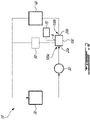
- Fig. 2 illustrates an oil system 20 for the engine 10, comprising a reservoir 30, a wet cavity 40 downstream of the reservoir 30, a pump 50 in fluid communication between the reservoir 30 and the wet cavity 40 and a valve 100 in fluid communication between the pump 50 and the wet cavity 40.
- the valve 100 is also in fluid communication with a return line 60, itself in fluid communication with the reservoir 50, via which the valve 100 may drain, for example upon the engine 10 shutting down.
- valve 100 and others described herein are so-called “pressure referenced” valve (or simply “referenced” valve), and thus is actuated to open or close based on, or in reference to, a pressure reference schematically shown at 70, for example a sensed fluid pressure somewhere in the fluid system.
- a referenced valve may be configured to open when the pressure of the fluid at a certain point in the fluid system (not necessarily on either side of the valve itself) reaches a threshold pressure value.
- the pressure reference 70 can in some cases be located at the reservoir 30 or at the wet cavity 40. Suitable locations for the pressure reference 70 within the fluid system include a fluid tank, a bearing cavity, and a gearbox, among others.
- the pressure reference 70 can also be external to the fluid system, and may be located for example in the main gas path of the engine 10 at the compressor section 14. Various other suitable locations for the pressure reference 70 are also possible, depending on the implementation of the valve 100.
- the pressure reference 70 may be a location at which the pressure is the lowest of any location of the fluid system, which may minimize a pressure drop of the fluid flowing across the valve 100.
- the valve 100 therefore has a pressure reference port R in fluid communication with the pressure reference 70, and is configured to operate (i.e., open or close) as a function of system pressures exerted onto the valve 100 such as a pressure exerted by the pump 50 and a pressure exerted by the pressure reference 70 via the reference port R.
- the valve 100 includes a housing 110 having an upstream end 100 a of the valve 100 defining an inlet passage P I , or inlet port, and a downstream end 100 b of the valve 100 defining an outlet passage P O , or outlet port.
- the housing 110 has a cylindrical shape and extends along a longitudinal axis A that extends through the valve 100.
- the upstream and downstream ends 100 a , 100 b project from opposite ends of the housing 110 in opposite directions parallel to the axis A, defining spouts sealingly receivable by fluid conduits 20a, 20b ( Figs.
- the upstream and downstream ends 100 a , 100 b are arranged for sealingly receiving the fluid conduits 20a, 20b.
- the housing 110 is embedded in another housing-type structure of the oil system 20 (for example an oil pump housing, an oil tank housing, a bearing cavity housing, a gearbox cavity housing, etc.) defining either conduit 20a, 20b, and may be said to form a unitary piece therewith.
- the housing 110 defines a chamber C along the axis A having an upstream end in fluid communication with the inlet passage P I and a downstream end in fluid communication with the outlet passage P O .
- the reference port R of the valve 100 is defined by the housing 110 and is in fluid communication with inside the chamber C.
- a piston assembly 120 of the valve 100 is sealingly received by the chamber C so as to close the chamber C at either end.
- the piston assembly 120 is structured and arranged so as to be clear of a portion of the chamber C that is in fluid communication with the reference port R.
- Radially outward of the chamber C relative to the axis A, the housing 110 defines an axially-extending passage referred to as a bypass passage P A .
- the bypass passage P A extends besides the chamber C away from the upstream end 100 a and toward the downstream end 100 b .
- the housing 110 defines a radially-extending upstream passage P Ra extending from the inlet passage P I to an upstream end of the bypass passage P A .
- the housing 110 defines a radially-extending downstream passage P Rb extending from a downstream end of the bypass passage P A to the outlet passage Po.
- the inlet passage P I , the upstream passage P Ra , the bypass passage P A , the downstream passage P Rb and the outlet passage Po are in serial flow communication so as to define a flow path through the valve 100.
- the flow path may be said to be routed through the valve 100 so as to circumvent the chamber C and the reference port R as it extends from the upstream end 100 a to the downstream end 100 b of the valve 100.
- the piston assembly 120 is arranged relatively to the housing 110 so as to selectively obstruct the flow path at the upstream passage P Ra , as will be described hereinbelow.
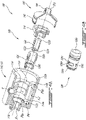
- the valve 100 is shown disassembled and circumferentially cutaway so as to exhibit interior features.
- the housing 110 has an interior-housing wall 112 defining a housing cavity about the axis A in fluid communication between the inlet passage P I and the outlet passage Po.
- the housing 110 also has a tubular rim 114 located in the housing cavity about the axis A.
- An exterior of the rim 114 defines the bypass passage P A
- an interior of the rim 114 defines the chamber C.
- the bypass passage P A is circumscribed radially outwardly by the inner-housing wall 112 and radially inwardly by the rim 114 relative to the axis A.
- the rim 114 is axially shorter than the inner-housing wall 112. Moreover, an upstream end 112 a and a downstream end 112 b of the inner-housing wall 112 are respectively axially spaced outwardly from an upstream end 114 a and a downstream end 114 b of the rim 114, leaving portions of the bypass passage P A radially inwardly unenclosed at either end of the rim 114.
- This arrangement of the rim 114 relative to the inner-housing wall 112 defines portions of the upstream passage P Ra and the downstream passage P Rb , which may also be referred to as housing windows defined by the housing 110 radially through the rim 114 on either side of the chamber C.
- the rim 114 extends axially to either one or both of the ends 112 a , 112 b of the inner-housing wall 112, and the housing windows are openings defined in a portion of the rim 114 surrounded by the inner-housing wall 112.
- the housing 110 is also provided with at least one web-like member, henceforth referred to as a rib 116, which extends radially outwardly relative to the axis A from the rim 114 to the inner-housing wall 112.
- a plurality of ribs 116 being circumferentially spaced apart from one another can be provided.
- the plurality of ribs 116 partition the bypass passage P A into a plurality of axially-extending channels.
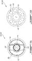
- two ribs 116 located diametrically opposite one another are provided ( Fig. 5A ) to support the rim 114 relative to the inner-housing wall 112, and define, together with the rim 114, a pair of C-shaped channels.
- the channels have a cylindrical shape ( Fig. 5B ).
- the housing 110 also defines an annular housing seat 118 surrounding a downstream end of the inlet passage P I , by way of which the housing 110 engages with the piston assembly 120 as will now be described.
- the piston assembly 120 includes a piston 122, a base 124, a biasing means (not shown) between the piston 122 and the base 124 and a sleeve 126 by which the piston 122 is slidably received.
- a first sleeve end of the sleeve 126 is sealingly received by the housing seat 118 and a second sleeve end of the sleeve 126 is sealingly received by the rim 114 within the chamber C.
- the sleeve 126 thus extends from inside the chamber C to the inlet passage P I , thereby extending across the upstream passage P Ra .
- An inner-sleeve wall 126a of the sleeve 126 defines an annular sleeve seat 126b located proximate to the first sleeve end on the inside of the sleeve 126. Between the sleeve seat 126b and the second sleeve end, slot-like openings, referred to henceforth as sleeve windows 126c, extend from inside the sleeve 126 to outside thereof. Upon the sleeve 126 being received by the housing seat 118, the sleeve windows 126c longitudinally align with and circumferentially overlap the housing windows, such that fluid flowing through the flow path may flow through the sleeve windows 126c.
- an overlap area of the sleeve windows 126c relative to the housing windows corresponds to at least a cross sectional area of the inlet passage P I or the outlet passage Po, whichever is the lesser, such that the sleeve windows 126c are not a restrictor of the flow path.
- three similarly shaped and equally spaced apart sleeve windows 126c are provided, in what is merely one of numerous suitable configurations of the sleeve 126.
- the base 124 is fastened to the housing 110, in this case via the rim 114, so as to hold the sleeve 126, with the piston 122 therein, in place relative to the housing 110.
- the piston 122 is movable relative to the housing 110 between a first valve position ( Fig. 7A ) in which the piston 122 obstructs the flow path at the upstream passage P RA and a second valve position ( Fig. 7B ) in which the piston 122 is at least partially clear of the flow path.
- the first and second valve positions may thus be respectively referred to as a closed position and an open position of the valve 100.
- the piston 122 encroaches the upstream passage P Ra .
- a first piston end 122a, or tip, of the piston 122 engages the sleeve seat 126b and blocks the flow path at the inlet passage P I .
- the first piston end 122a has a shape complementary to that of the sleeve seat 126b. A portion of the piston 122 proximate to the first piston end 122a blocks the flow path at the sleeve windows 126c. In some embodiments, the sleeve 126 is omitted, and the piston is slidably received by the rim 114. In such embodiments, the first piston end 122a engages the housing seat 118 when in the closed valve position so as to block the flow path at the inlet passage P I .
- the biasing means biases the piston 122 toward the first valve position under a certain biasing force.
- the biasing force is selected to be suitable for biasing the piston 122 in the first valve position upon any pressures exerted by fluids against the piston 122 being either balanced or absent, as the case may be during shutdown of the engine 10.
- the biasing force can be adjusted by any suitable way, such as by adjusting mechanical properties of the spring including a nominal length and/or stiffness of the spring.
- the second piston end 122b defines a recess 122c, and the biasing means engages a bottom surface of the recess 122c.
- a portion of the chamber C partially enclosed by the piston assembly 120 is in fluid communication with the reference port R.
- a reference fluid which may be oil or a gas, is injected in the chamber C via the reference port R, thereby further urging the piston 122 toward the first position.
- the spring can be adjusted such that the piston 122 requires a pressure greater than that in effect at the reference port R by a predetermined amount in order to be moved from the first valve position to the second valve position.
- Increasing the stiffness of the spring can in some cases desirably lessen the effect of sudden pressure variations, such as a sudden pressure drop at the reference port R or a sudden pressure increase at the inlet passage P I .
- the biasing means is omitted, such that the piston 122 is biased toward the first valve position under the sole influence of the reference fluid, provided that a suitable pressure is in effect at the reference port R.
- the flow path defining features described hereinabove allow circumvention of the reference port R by the flow path, such that the reference port R may be located between the inlet passage P I and the outlet passage P O , i.e., at a location axially closer to the inlet passage P I than a location of the outlet passage P O .
- the inlet passage P I and the outlet passage Po respectively extend along an inlet axis and an outlet axis that are collinear to the axis A.
- the inlet passage P I , the chamber C and the outlet passage Po are concentric.
- one or both of the inlet axis and the outlet axis may be at an angle to the axis A or transversely offset relative to the axis A.
- the housing 110 is constructed of multiple pieces structured and arranged such that one such piece defining the chamber C is detachable from another such piece defining one of the upstream and downstream ends 100 a , 100 b of the valve 100.
- the housing 110 includes a body 130 having the upstream end 100 a of the valve 100, and a tubular member, referred to henceforth as a transfer tube 140, having the downstream end 100 b of the valve 100 and being detachable from the body 130.
- the transfer tube 140 extends along the outlet axis.
- the transfer tube 140 has a proximal tube portion 142 slidably received by the body 130 alongside the inner-housing wall 112, and a distal tube portion 144 defining the outlet passage P O .
- the body 130 is instead slidably received by the proximal tube portion 142.
- the transfer tube 140 tapers and cooperates with the body 130 to define the downstream passage P Rb .
- the downstream passage P Rb is fully defined by the body 130, and the transfer tube 140 is located downstream thereof.
- an axial length of the valve 100 is selectively variable, and various means can be used to selectively position the transfer tube 140 relative to the body 130.
- an annular body flange 132 of the body 130 extending radially outwardly relative to the inner-housing wall 112 can act as an abutment for limiting axial movement of the transfer tube 140 toward the upstream end 100 a of the valve 100.
- a C-clip (or other like fastener) engaged in an annular, radially outer tube groove 146 defined by the proximal tube portion 142 can abut the body flange 132, thereby stopping the transfer tube 140.
- the proximal tube portion 142 can define a plurality of tube grooves 146 spaced from one another, each allowing to selectively place the C-clip to stop the transfer tube 140 at a different offset relative to the body 130.
- the proximal tube portion 142 may be threadedly engaged with a nut 148 disposed therearound, and abut the body flange 132 via the nut 148.
- axial movement of the transfer tube 140 away from the upstream end 100 a of the valve 100 can be limited by any one of several suitable means. For example, as shown in Fig.
- the body 130 may have an axially-extending wall 134 located radially outward of the flange 132 defining an annular, radially inner body groove 136 by which a C-clip (or other like fastener) may be received.
- the C-clip may engage the transfer tube 140 directly or indirectly via another C-clip fitted thereto.
- a flanged nut 138 threadedly engaged with the body 130 may be used to limit the outward movement of the transfer tube 140.
- the valve 100 is shown in a retracted position, in which the transfer tube 140 is received by the body 130 such that the axial length, i.e., a distance between the upstream and downstream ends 100 a , 100 b of the valve 100, is minimized.
- the proximal tube portion 142 is received by an annular, axially-extending recess 139 defined by the body 130 at a location radially inward of the inner-housing wall 112 and axially inward the ribs 116.
- the recess 139 is also shown in Fig. 5A .
- Fig. 5A In Fig.
- the valve 100 is shown in an extended position in which the transfer tube 140 is held relative to the body 130 such that the axial length, i.e., the distance between the upstream and downstream ends 100 a , 100 b of the valve 100, is maximized.
- the extended position corresponds to a distance between fixed ends of the fluid conduits 20a, 20b of the oil system 20.
- the valve 100 may be aligned with the fluid conduits 20a, 20b upon being in the retracted position and, once in alignment, be moved into the extended position to connect to the fluid conduits 20a, 20b.
- the body 130 is integral to a housing defining the fixed end of the fluid conduit 20a.
- the transfer tube 140 is integral to a housing defining the fixed end of the fluid conduit 20b.
- the outlet passage Po is a first outlet passage P O1
- the inlet passage P I , the upstream passage P Ra , the axial passage P A , the downstream passage P Rb and the first outlet passage Po are in serial flow communication so as to define a first flow path through the valve 100.
- the housing 110 defines a second outlet passage P O2 located axially between the inlet passage P I and the reference port R.
- the second outlet passage P O2 is in fluid communication with the inlet passage P I , at a location upstream of the upstream passage P Ra , defining a second flow path therewith through the valve 100.
- the second flow path may for example be upstream of the return line 60.
- the first piston end 122a is hollow. Stated otherwise, the piston 122 has a hollow piston portion extending from the first piston end 122a toward the second piston end 122b. The piston 122 defines a port 122d extending radially outwardly from inside the hollow piston portion to outside the piston 122.
- the piston 122 is movable relative to the housing 110 between a first valve position ( Fig. 11A ) and a second valve position ( Fig. 11B ). In the first valve position, the piston 122 at least partially obstructs the first flow path at the upstream passage P RA , yet remains at least partially clear of the second flow path as the port 122d communicates with the second outlet passage P O2 .
- the inlet passage P I is in fluid communication with the second outlet passage P O2 via the hollow piston portion.
- the piston 122 at least partially obstructs the second flow path yet remains at least partially clear of the first flow path as the port 122d communicates with the first outlet passage P O1 .
- the inlet passage P I is in fluid communication with the first outlet passage P O1 via the hollow piston portion. Hence, fluid may flow through the valve 100 regardless of the position of the piston 122.
- most but not all of the flow of fluid entering the valve 100 via the inlet passage P I exits the valve 100 via the second outlet passage P O2 when the piston 122 is in the first valve position, and exits the valve 100 via the first outlet passage P O1 when the piston 122 is in the second valve position.
- Figs. such as the one depicted in Figs.
- the valve 100 is referred to as a bypass valve, i.e., 100% of the fluid entering the valve 100 via the inlet passage P I exits the valve 100 via the second outlet passage P O2 when the piston 122 is in the first valve position, and exits the valve 100 via the first outlet passage P O1 when the piston 122 is in the second valve position.
Landscapes
- Engineering & Computer Science (AREA)
- General Engineering & Computer Science (AREA)
- Mechanical Engineering (AREA)
- Physics & Mathematics (AREA)
- Fluid Mechanics (AREA)
- Lift Valve (AREA)
- Valve Housings (AREA)
- Safety Valves (AREA)
Abstract
Description
- This disclosure relates generally to fluid systems and valves therefore, and more particularly to pressure referenced valves for use in, for example, an oil system of a gas turbine engine or the like.
- Various valves are used for controlling and/or selectively permitting fluid flow between a source and a wet component, for example check valves which are used to open or close an oil path from a reservoir to a bearing in a gearbox. The opening and closing of such check valves can be triggered by various mechanisms. While existing valves may suit their intended purpose, there remains room for improvement in the art, for instance where space, weight and/or part count pertaining to such valves are design concerns.
- There is accordingly provided a valve for use in a fluid system, the valve comprising: a housing having an inlet passage, an outlet passage spaced axially spaced apart from the inlet passage relative to a longitudinal axis extending through the housing, and a pressure reference port located axially between the inlet passage and the outlet passage, the housing including: an inner-housing wall enclosing a housing cavity providing fluid communication between the inlet passage and the outlet passage; a rim in the housing cavity extending circumferentially about the longitudinal axis, the rim defining an axially-extending bypass passage circumscribed radially outwardly by the inner-housing wall and radially inwardly by the rim, a radially-extending upstream passage located axially between an upstream end of the housing cavity and the rim, and a radially-extending downstream passage located axially between the rim and a downstream end of the housing cavity, wherein the inlet passage, the upstream passage, the bypass passage, the downstream passage and the outlet passage are in serial flow communication so as to define a flow path through the valve; a chamber circumscribed radially outwardly by the rim, the chamber in fluid communication with the pressure reference port; a rib extending radially outwardly from the rim to the inner-housing wall, through the bypass passage; and a piston assembly received within the chamber, the piston assembly including a piston movable axially relative to the rim between a first valve position in which the piston obstructs the flow path at the upstream passage and a second valve position in which the piston is at least partially clear of the flow path to permit fluid flow along the flow path.
- The valve as defined above and described herein may also include one or more of the following features, in whole or in part, and in any combination.
- In certain aspects, the housing includes a body defining the inlet passage and a transfer tube defining the outlet passage, the transfer tube slidably received by the body.
- In certain aspects, the transfer tube extends axially relative to an outlet axis and is slidable along the outlet axis relative to the housing, the outlet axis being at least one of at an angle relative to the longitudinal axis and radially offset relative to the longitudinal axis.
- In certain aspects, the inlet passage is disposed about the longitudinal axis.
- In certain aspects, the transfer tube is fastenable to the body so as to hold the outlet passage in place relative to the inlet passage.
- In certain aspects, the rib is one of a plurality of ribs circumferentially spaced apart from one another, the plurality of ribs partitioning the bypass passage into a plurality of axially-extending channels.
- In certain aspects, the channels have a cylindrical shape.
- In certain aspects, the pressure reference port is in fluid communication between a portion of the chamber partially enclosed by the piston assembly and outside the valve.
- In certain aspects, the piston assembly further comprises a biasing means adjusted to bias the piston toward the first valve position.
- In certain aspects, the outlet passage is a first outlet passage, the housing defining a second outlet passage in fluid communication with the inlet passage, the second outlet passage located closer to the inlet passage than the pressure reference port.
- In certain aspects, when the piston is in the first valve position, the piston obstructs the second outlet passage and when the piston is in the second valve position, the piston is at least partially clear of the second outlet passage.
- In certain aspects, the piston has a first piston end proximate to the inlet passage, a second piston end opposite the first piston end, and a hollow piston portion extending from the first piston end toward the second piston end, the piston defining a port extending radially outwardly from inside the hollow piston portion to outside the hollow piston portion, the inlet passage in fluid communication with inside the hollow piston portion via the first piston end upon the piston being either in the first valve position or in the second valve position, the second outlet passage being in fluid communication with the inlet passage via the port upon the piston being in the first valve position and the first outlet passage being in fluid communication with the inlet passage via the port upon the piston being in the second valve position.
- There is also provided a fluid system for a gas turbine engine, the fluid system comprising: a reservoir for receiving a fluid; a valve downstream of the reservoir and having a valve inlet in fluid communication therewith, the valve including: a housing including: an inlet passage defining the valve inlet, an outlet passage spaced axially spaced from the inlet passage relative to a longitudinal axis extending through the housing, and a pressure reference port located axially between the inlet passage and the inlet passage, the outlet passage defining a valve outlet; an axially-extending bypass passage radially outward of the longitudinal axis; a radially-extending upstream passage in fluid communication between the inlet passage and an upstream end of the bypass passage; a radially-extending downstream passage in fluid communication between a downstream end of the bypass passage and the outlet passage, wherein the inlet passage, the upstream passage, the bypass passage, the downstream passage and the outlet passage are in serial flow communication so as to define a flow path through the valve, and a chamber extending axially between the upstream passage and the downstream passage, the chamber in fluid communication with the pressure reference port; a piston assembly received by the chamber, the piston assembly including a piston movable axially relative to the chamber between a first valve position in which the piston obstructs the flow path at the upstream passage and a second valve position in which the piston is at least partially clear of the flow path to permit fluid flow along the flow path; and a wet cavity downstream of the valve and in fluid flow communication with the valve outlet.
- The fluid system as defined above and described herein may also include one or more of the following features, in whole or in part, and in any combination.
- In certain aspects, the fluid system further comprises a pump upstream of the valve inlet and a pressure reference in fluid flow communication with the pressure reference port.
- In certain aspects, the pressure reference port provides fluid communication between a portion of the chamber partially enclosed by the piston assembly and a region outside the valve.
- In certain aspects, the piston assembly further comprises a biasing means adjusted to bias the piston toward the first valve position.
- In certain aspects, the outlet passage is a first outlet passage, the housing defining a second outlet passage in fluid communication with the inlet passage, the second outlet passage located closer to the inlet passage than the pressure reference port.
- In certain aspects, a return line is downstream of the second outlet passage, the return line in fluid communication with the reservoir.
- In certain aspects, the housing includes a body defining the inlet passage and the pressure reference port, and a transfer tube defining the outlet passage, the transfer tube slidably received by the body.
- In certain aspects, the transfer tube extends axially relative to an outlet axis and is slidable along the outlet axis relative to the body, the outlet axis being at least one of at an angle relative to the longitudinal axis and radially offset relative to the longitudinal axis.
- Reference is now made to the accompanying figures in which:
-
Fig. 1 is a schematic cross sectional view of a gas turbine engine; -
Fig. 2 is a schematic representation of a fluid system of the gas turbine engine ofFig. 1 ; -
Fig. 3 is a cutaway, partially sectioned, perspective view of a valve of the fluid system ofFig. 2 , with a spring of the valve having been removed for clarity; -
Fig. 4A is an exploded view of the valve ofFig. 3 ; -
Fig. 4B is a perspective view of a sleeve of the valve ofFig. 3 ; -
Fig. 5A is an end elevation view of a housing body of the valve ofFig. 3 ; -
Fig. 5B is another end elevation view of a housing body of a valve of the fluid system ofFig. 2 ; -
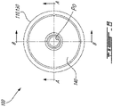
Fig. 6 is an elevation view of the valve ofFig. 3 ; -
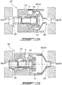
Fig. 7A is a cross sectional view of the valve ofFig. 3 taken along the line A-A ofFig. 6 , with the valve shown in a closed valve position; -
Fig. 7B is a cross sectional view of the valve ofFig. 3 taken along the line A-A ofFig. 6 , with the valve shown in an open valve position; -
Fig. 8A is a cross sectional view of the valve according to an embodiment; -
Fig. 8B is a cross sectional view of the valve according to an embodiment; -
Fig. 9A is a cross sectional view of the valve according to an embodiment; -
Fig. 9B is a cross sectional view of the valve according to an embodiment; -
Fig. 10A is a cross sectional view of the valve ofFig. 3 taken along the line B-B ofFig. 6 , with the valve shown in the closed valve position and in a retracted position; -
Fig. 10B is a cross sectional view of the valve ofFig. 3 taken along the line B-B ofFig. 6 , with the valve shown in the closed valve position and in an extended position; -
Fig. 11A is a schematic representation of a valve according to another embodiment, with the valve shown in a first valve position, and -
Fig. 11B is a schematic representation of the valve ofFig. 11A , with the valve shown in a second valve position. -
Fig. 1 illustrates anaircraft engine 10 of a type preferably provided for use in subsonic flight, such as for example a gas turbine engine generally comprising in serial flow communication afan 12 through which ambient air is propelled, acompressor section 14 for pressurizing the air, acombustor 16 in which the compressed air is mixed with fuel and ignited for generating an annular stream of hot combustion gases, and aturbine section 18 for extracting energy from the combustion gases. - Although the present technology will generally be described in an exemplary manner with respect to an
oil system 20 of theengine 10, it shall be understood that it may also be implemented, mutatis mutandis, in any other fluid system of theengine 10, such as for example a fuel system. Additionally, the valves as described herein may also be implemented in other types of fluid systems. -
Fig. 2 illustrates anoil system 20 for theengine 10, comprising areservoir 30, a wet cavity 40 downstream of thereservoir 30, apump 50 in fluid communication between thereservoir 30 and the wet cavity 40 and avalve 100 in fluid communication between thepump 50 and the wet cavity 40. Thevalve 100 is also in fluid communication with areturn line 60, itself in fluid communication with thereservoir 50, via which thevalve 100 may drain, for example upon theengine 10 shutting down. - The
valve 100 and others described herein are so-called "pressure referenced" valve (or simply "referenced" valve), and thus is actuated to open or close based on, or in reference to, a pressure reference schematically shown at 70, for example a sensed fluid pressure somewhere in the fluid system. Indeed, a referenced valve may be configured to open when the pressure of the fluid at a certain point in the fluid system (not necessarily on either side of the valve itself) reaches a threshold pressure value. Thepressure reference 70 can in some cases be located at thereservoir 30 or at the wet cavity 40. Suitable locations for thepressure reference 70 within the fluid system include a fluid tank, a bearing cavity, and a gearbox, among others. Nevertheless, thepressure reference 70 can also be external to the fluid system, and may be located for example in the main gas path of theengine 10 at thecompressor section 14. Various other suitable locations for thepressure reference 70 are also possible, depending on the implementation of thevalve 100. Thepressure reference 70 may be a location at which the pressure is the lowest of any location of the fluid system, which may minimize a pressure drop of the fluid flowing across thevalve 100. - The
valve 100 therefore has a pressure reference port R in fluid communication with thepressure reference 70, and is configured to operate (i.e., open or close) as a function of system pressures exerted onto thevalve 100 such as a pressure exerted by thepump 50 and a pressure exerted by thepressure reference 70 via the reference port R. - With reference to
Figs. 3 to 6 , thevalve 100 will be described in greater detail. As illustrated inFig. 3 , thevalve 100 includes ahousing 110 having anupstream end 100a of thevalve 100 defining an inlet passage PI, or inlet port, and adownstream end 100b of thevalve 100 defining an outlet passage PO, or outlet port. In this embodiment, thehousing 110 has a cylindrical shape and extends along a longitudinal axis A that extends through thevalve 100. The upstream and downstream ends 100a, 100b project from opposite ends of thehousing 110 in opposite directions parallel to the axis A, defining spouts sealingly receivable byfluid conduits Figs. 2 ,10A, 10B ) of theoil system 20 respectively located upstream and downstream of thevalve 100. In certain other embodiments, the upstream and downstream ends 100a, 100b are arranged for sealingly receiving thefluid conduits housing 110 is embedded in another housing-type structure of the oil system 20 (for example an oil pump housing, an oil tank housing, a bearing cavity housing, a gearbox cavity housing, etc.) defining eitherconduit - On the inside, the
housing 110 defines a chamber C along the axis A having an upstream end in fluid communication with the inlet passage PI and a downstream end in fluid communication with the outlet passage PO. The reference port R of thevalve 100 is defined by thehousing 110 and is in fluid communication with inside the chamber C. Apiston assembly 120 of thevalve 100 is sealingly received by the chamber C so as to close the chamber C at either end. Thepiston assembly 120, as will be described, is structured and arranged so as to be clear of a portion of the chamber C that is in fluid communication with the reference port R. Radially outward of the chamber C relative to the axis A, thehousing 110 defines an axially-extending passage referred to as a bypass passage PA. The bypass passage PA extends besides the chamber C away from theupstream end 100a and toward thedownstream end 100b. Upstream of the chamber C, thehousing 110 defines a radially-extending upstream passage PRa extending from the inlet passage PI to an upstream end of the bypass passage PA. Downstream of the chamber C, thehousing 110 defines a radially-extending downstream passage PRb extending from a downstream end of the bypass passage PA to the outlet passage Po. The inlet passage PI, the upstream passage PRa, the bypass passage PA, the downstream passage PRb and the outlet passage Po are in serial flow communication so as to define a flow path through thevalve 100. The flow path may be said to be routed through thevalve 100 so as to circumvent the chamber C and the reference port R as it extends from theupstream end 100a to thedownstream end 100b of thevalve 100. Thepiston assembly 120 is arranged relatively to thehousing 110 so as to selectively obstruct the flow path at the upstream passage PRa, as will be described hereinbelow. - In
Fig. 4A , thevalve 100 is shown disassembled and circumferentially cutaway so as to exhibit interior features. As shown inFig. 4A , thehousing 110 has an interior-housing wall 112 defining a housing cavity about the axis A in fluid communication between the inlet passage PI and the outlet passage Po. Thehousing 110 also has atubular rim 114 located in the housing cavity about the axis A. An exterior of therim 114 defines the bypass passage PA, whereas an interior of therim 114 defines the chamber C. The bypass passage PA is circumscribed radially outwardly by the inner-housing wall 112 and radially inwardly by therim 114 relative to the axis A. It shall be noted that in this embodiment, therim 114 is axially shorter than the inner-housing wall 112. Moreover, anupstream end 112a and adownstream end 112b of the inner-housing wall 112 are respectively axially spaced outwardly from anupstream end 114a and adownstream end 114b of therim 114, leaving portions of the bypass passage PA radially inwardly unenclosed at either end of therim 114. This arrangement of therim 114 relative to the inner-housing wall 112 defines portions of the upstream passage PRa and the downstream passage PRb, which may also be referred to as housing windows defined by thehousing 110 radially through therim 114 on either side of the chamber C. In some embodiments, therim 114 extends axially to either one or both of theends housing wall 112, and the housing windows are openings defined in a portion of therim 114 surrounded by the inner-housing wall 112. - The
housing 110 is also provided with at least one web-like member, henceforth referred to as arib 116, which extends radially outwardly relative to the axis A from therim 114 to the inner-housing wall 112. Depending on the embodiment, a plurality ofribs 116 being circumferentially spaced apart from one another can be provided. The plurality ofribs 116 partition the bypass passage PA into a plurality of axially-extending channels. For example, in this embodiment, tworibs 116 located diametrically opposite one another are provided (Fig. 5A ) to support therim 114 relative to the inner-housing wall 112, and define, together with therim 114, a pair of C-shaped channels. In some embodiments, more than two channels are provided. In some embodiments, the channels have a cylindrical shape (Fig. 5B ). Thehousing 110 also defines anannular housing seat 118 surrounding a downstream end of the inlet passage PI, by way of which thehousing 110 engages with thepiston assembly 120 as will now be described. - Still referring to
Fig. 4A , thepiston assembly 120 includes apiston 122, abase 124, a biasing means (not shown) between thepiston 122 and thebase 124 and asleeve 126 by which thepiston 122 is slidably received. A first sleeve end of thesleeve 126 is sealingly received by thehousing seat 118 and a second sleeve end of thesleeve 126 is sealingly received by therim 114 within the chamber C. Thesleeve 126 thus extends from inside the chamber C to the inlet passage PI, thereby extending across the upstream passage PRa. An inner-sleeve wall 126a of thesleeve 126 defines anannular sleeve seat 126b located proximate to the first sleeve end on the inside of thesleeve 126. Between thesleeve seat 126b and the second sleeve end, slot-like openings, referred to henceforth assleeve windows 126c, extend from inside thesleeve 126 to outside thereof. Upon thesleeve 126 being received by thehousing seat 118, thesleeve windows 126c longitudinally align with and circumferentially overlap the housing windows, such that fluid flowing through the flow path may flow through thesleeve windows 126c. Preferably, an overlap area of thesleeve windows 126c relative to the housing windows corresponds to at least a cross sectional area of the inlet passage PI or the outlet passage Po, whichever is the lesser, such that thesleeve windows 126c are not a restrictor of the flow path. Here, as best seen inFig. 4B , three similarly shaped and equally spaced apartsleeve windows 126c are provided, in what is merely one of numerous suitable configurations of thesleeve 126. Thebase 124 is fastened to thehousing 110, in this case via therim 114, so as to hold thesleeve 126, with thepiston 122 therein, in place relative to thehousing 110. - Referring to
Figs. 6-7B , thepiston 122 is movable relative to thehousing 110 between a first valve position (Fig. 7A ) in which thepiston 122 obstructs the flow path at the upstream passage PRA and a second valve position (Fig. 7B ) in which thepiston 122 is at least partially clear of the flow path. The first and second valve positions may thus be respectively referred to as a closed position and an open position of thevalve 100. In the first valve position, thepiston 122 encroaches the upstream passage PRa. Afirst piston end 122a, or tip, of thepiston 122 engages thesleeve seat 126b and blocks the flow path at the inlet passage PI. Preferably, thefirst piston end 122a has a shape complementary to that of thesleeve seat 126b. A portion of thepiston 122 proximate to thefirst piston end 122a blocks the flow path at thesleeve windows 126c. In some embodiments, thesleeve 126 is omitted, and the piston is slidably received by therim 114. In such embodiments, thefirst piston end 122a engages thehousing seat 118 when in the closed valve position so as to block the flow path at the inlet passage PI. - The biasing means, in this case provided in the form of a spring having opposite ends respectively engaging the
base 124 and asecond piston end 122b of thepiston 122, biases thepiston 122 toward the first valve position under a certain biasing force. The biasing force is selected to be suitable for biasing thepiston 122 in the first valve position upon any pressures exerted by fluids against thepiston 122 being either balanced or absent, as the case may be during shutdown of theengine 10. The biasing force can be adjusted by any suitable way, such as by adjusting mechanical properties of the spring including a nominal length and/or stiffness of the spring. Conversely, this can be done by replacing the spring with another having a different length and/or stiffness, but also by way of a spacing means, such as one or more shims, inserted at one or both ends of the spring. In the depicted embodiment, thesecond piston end 122b defines arecess 122c, and the biasing means engages a bottom surface of therecess 122c. Proximate to thesecond piston end 122b and thebase 124, a portion of the chamber C partially enclosed by thepiston assembly 120 is in fluid communication with the reference port R. A reference fluid, which may be oil or a gas, is injected in the chamber C via the reference port R, thereby further urging thepiston 122 toward the first position. Thus, to move thepiston 122 from the first valve position to the second valve position, a force greater than the sum of those exerted by the spring and by the reference fluid against thesecond piston end 122b must be exerted against thefirst piston end 122a. Hence, the spring can be adjusted such that thepiston 122 requires a pressure greater than that in effect at the reference port R by a predetermined amount in order to be moved from the first valve position to the second valve position. Increasing the stiffness of the spring can in some cases desirably lessen the effect of sudden pressure variations, such as a sudden pressure drop at the reference port R or a sudden pressure increase at the inlet passage PI. In some embodiments, the biasing means is omitted, such that thepiston 122 is biased toward the first valve position under the sole influence of the reference fluid, provided that a suitable pressure is in effect at the reference port R. - Whereas conventional referenced valves have their outlet located between their inlet and their pressure reference port, it should be noted that the flow path defining features described hereinabove allow circumvention of the reference port R by the flow path, such that the reference port R may be located between the inlet passage PI and the outlet passage PO, i.e., at a location axially closer to the inlet passage PI than a location of the outlet passage PO. This renders possible various spatial arrangements of the inlet passage PI and of the outlet passage PO relative to one another. For example, in this exemplary embodiment, the inlet passage PI and the outlet passage Po respectively extend along an inlet axis and an outlet axis that are collinear to the axis A. Stated otherwise, the inlet passage PI, the chamber C and the outlet passage Po are concentric. In other embodiments, one or both of the inlet axis and the outlet axis may be at an angle to the axis A or transversely offset relative to the axis A.
- Moreover, in this exemplary embodiment, the
housing 110 is constructed of multiple pieces structured and arranged such that one such piece defining the chamber C is detachable from another such piece defining one of the upstream and downstream ends 100a, 100b of thevalve 100. In this particular arrangement, thehousing 110 includes abody 130 having theupstream end 100a of thevalve 100, and a tubular member, referred to henceforth as atransfer tube 140, having thedownstream end 100b of thevalve 100 and being detachable from thebody 130. Thetransfer tube 140 extends along the outlet axis. Thetransfer tube 140 has aproximal tube portion 142 slidably received by thebody 130 alongside the inner-housing wall 112, and adistal tube portion 144 defining the outlet passage PO. In other embodiments, thebody 130 is instead slidably received by theproximal tube portion 142. As it extends axially from theproximal tube portion 142 to thedistal tube portion 144, thetransfer tube 140 tapers and cooperates with thebody 130 to define the downstream passage PRb. In other embodiments, the downstream passage PRb is fully defined by thebody 130, and thetransfer tube 140 is located downstream thereof. - In some embodiments, an axial length of the
valve 100 is selectively variable, and various means can be used to selectively position thetransfer tube 140 relative to thebody 130. For instance, referring toFigs. 7A-7B , anannular body flange 132 of thebody 130 extending radially outwardly relative to the inner-housing wall 112 can act as an abutment for limiting axial movement of thetransfer tube 140 toward theupstream end 100a of thevalve 100. A C-clip (or other like fastener) engaged in an annular, radiallyouter tube groove 146 defined by theproximal tube portion 142 can abut thebody flange 132, thereby stopping thetransfer tube 140. As shown inFig. 8A , in certain embodiments, theproximal tube portion 142 can define a plurality oftube grooves 146 spaced from one another, each allowing to selectively place the C-clip to stop thetransfer tube 140 at a different offset relative to thebody 130. Alternatively, as shown inFig. 8B , theproximal tube portion 142 may be threadedly engaged with anut 148 disposed therearound, and abut thebody flange 132 via thenut 148. Conversely, axial movement of thetransfer tube 140 away from theupstream end 100a of thevalve 100 can be limited by any one of several suitable means. For example, as shown inFig. 9A , thebody 130 may have an axially-extendingwall 134 located radially outward of theflange 132 defining an annular, radiallyinner body groove 136 by which a C-clip (or other like fastener) may be received. The C-clip may engage thetransfer tube 140 directly or indirectly via another C-clip fitted thereto. Alternatively, as shown inFig. 9B , a flanged nut 138 threadedly engaged with thebody 130 may be used to limit the outward movement of thetransfer tube 140. - Referring to
Fig. 10A , thevalve 100 is shown in a retracted position, in which thetransfer tube 140 is received by thebody 130 such that the axial length, i.e., a distance between the upstream and downstream ends 100a, 100b of thevalve 100, is minimized. In the retracted position, theproximal tube portion 142 is received by an annular, axially-extendingrecess 139 defined by thebody 130 at a location radially inward of the inner-housing wall 112 and axially inward theribs 116. Therecess 139 is also shown inFig. 5A . InFig. 10B , thevalve 100 is shown in an extended position in which thetransfer tube 140 is held relative to thebody 130 such that the axial length, i.e., the distance between the upstream and downstream ends 100a, 100b of thevalve 100, is maximized. In this arrangement, the extended position corresponds to a distance between fixed ends of thefluid conduits oil system 20. Thevalve 100 may be aligned with thefluid conduits fluid conduits body 130 is integral to a housing defining the fixed end of thefluid conduit 20a. In embodiments, thetransfer tube 140 is integral to a housing defining the fixed end of thefluid conduit 20b. - With reference to
Figs. 11A and 11B , another embodiment of the present technology will now be described, in which the outlet passage Po is a first outlet passage PO1, and the inlet passage PI, the upstream passage PRa, the axial passage PA, the downstream passage PRb and the first outlet passage Po are in serial flow communication so as to define a first flow path through thevalve 100. In this embodiment, thehousing 110 defines a second outlet passage PO2 located axially between the inlet passage PI and the reference port R. The second outlet passage PO2 is in fluid communication with the inlet passage PI, at a location upstream of the upstream passage PRa, defining a second flow path therewith through thevalve 100. The second flow path may for example be upstream of thereturn line 60. - In this embodiment, the
first piston end 122a is hollow. Stated otherwise, thepiston 122 has a hollow piston portion extending from thefirst piston end 122a toward thesecond piston end 122b. Thepiston 122 defines aport 122d extending radially outwardly from inside the hollow piston portion to outside thepiston 122. Thepiston 122 is movable relative to thehousing 110 between a first valve position (Fig. 11A ) and a second valve position (Fig. 11B ). In the first valve position, thepiston 122 at least partially obstructs the first flow path at the upstream passage PRA, yet remains at least partially clear of the second flow path as theport 122d communicates with the second outlet passage PO2. The inlet passage PI is in fluid communication with the second outlet passage PO2 via the hollow piston portion. In the second valve position, thepiston 122 at least partially obstructs the second flow path yet remains at least partially clear of the first flow path as theport 122d communicates with the first outlet passage PO1. The inlet passage PI is in fluid communication with the first outlet passage PO1 via the hollow piston portion. Hence, fluid may flow through thevalve 100 regardless of the position of thepiston 122. In some embodiments, most but not all of the flow of fluid entering thevalve 100 via the inlet passage PI exits thevalve 100 via the second outlet passage PO2 when thepiston 122 is in the first valve position, and exits thevalve 100 via the first outlet passage PO1 when thepiston 122 is in the second valve position. In some such embodiments, fluid exits thevalve 100 at a given rate regardless of the position of thepiston 122. In some other embodiments such as the one depicted inFigs. 11A, 11B , thevalve 100 is referred to as a bypass valve, i.e., 100% of the fluid entering thevalve 100 via the inlet passage PI exits thevalve 100 via the second outlet passage PO2 when thepiston 122 is in the first valve position, and exits thevalve 100 via the first outlet passage PO1 when thepiston 122 is in the second valve position. - The embodiments described in this document provide non-limiting examples of possible implementations of the present technology. Upon review of the present disclosure, a person of ordinary skill in the art will recognize that changes may be made to the embodiments described herein without departing from the scope of the present technology. Indeed, various modifications could be implemented by a person of ordinary skill in the art in view of the present disclosure, which modifications would be within the scope of the present technology.
Claims (14)
- A valve (100) for use in a fluid system (20), the valve (100) comprising:a housing (110) having an inlet passage (PI), an outlet passage (PO) axially spaced apart from the inlet passage (PI) relative to a longitudinal axis (A) extending through the housing (110), and a pressure reference port (R) located axially between the inlet passage (PI) and the outlet passage (PO), the housing (110) including:an inner-housing wall (112) enclosing a housing cavity providing fluid communication between the inlet passage (PI) and the outlet passage (PO);a rim (114) in the housing cavity extending circumferentially about the longitudinal axis (A), the rim (114) defining an axially-extending bypass passage (PA) circumscribed radially outwardly by the inner-housing wall (112) and radially inwardly by the rim (114), a radially-extending upstream passage (PRa) located axially between an upstream end of the housing cavity and the rim (114), and a radially-extending downstream passage (PRb) located axially between the rim (114) and a downstream end of the housing cavity, wherein the inlet passage (PI), the upstream passage (PO), the bypass passage (PA), the downstream passage (PRb) and the outlet passage (Po) are in serial flow communication so as to define a flow path through the valve (100);a chamber (C) circumscribed radially outwardly by the rim (114), the chamber (C) in fluid communication with the pressure reference port (R);a rib (116) extending radially outwardly from the rim (114) to the inner-housing wall (112), through the bypass passage (PA); anda piston assembly (120) received within the chamber (C), the piston assembly (120) including a piston (122) movable axially relative to the rim (114) between a first valve position in which the piston (122) obstructs the flow path at the upstream passage (PRa) and a second valve position in which the piston (122) is at least partially clear of the flow path to permit fluid flow along the flow path.
- The valve (100) of claim 1, wherein the housing (110) includes a body (130) defining the inlet passage (PI) and a transfer tube (140) defining the outlet passage (PO), the transfer tube (140) slidably received by the body (130).
- The valve (100) of claim 2, wherein the transfer tube (140) extends axially relative to an outlet axis and is slidable along the outlet axis relative to the housing (110), the outlet axis being at least one of at an angle relative to the longitudinal axis (A) and radially offset relative to the longitudinal axis (A).
- The valve (100) of any preceding claim, wherein the inlet passage (PI) is disposed about the longitudinal axis (A).
- The valve (100) of claim 2, or of claim 3 or 4 as dependent on claim 2, wherein the transfer tube (140) is fastenable to the body (130) so as to hold the outlet passage (Po) in place relative to the inlet passage (PI).
- The valve (100) of any one of the preceding claims, wherein the rib (116) is one of a plurality of ribs (116) circumferentially spaced apart from one another, the plurality of ribs (116) partitioning the bypass passage (PA) into a plurality of axially-extending channels, the channels optionally having a cylindrical shape.
- The valve (100) of any one of the preceding, wherein the pressure reference port (R) is in fluid communication between a portion of the chamber (C) partially enclosed by the piston assembly (120) and outside the valve (100).
- The valve (100) of any one of the preceding, wherein the piston assembly (120) further comprises a biasing means adjusted to bias the piston (122) toward the first valve position.
- The valve (100) of any one of the preceding, wherein the outlet passage (Po) is a first outlet passage (PO1), the housing (110) defining a second outlet passage (PO2) in fluid communication with the inlet passage (PI), the second outlet passage (PO2) located closer to the inlet passage (PI) than the pressure reference port (R).
- The valve (100) of claim 9, wherein when the piston (122) is in the first valve position, the piston (122) obstructs the second outlet passage (PO2) and when the piston (122) is in the second valve position, the piston (122) is at least partially clear of the second outlet passage (PO2).
- The valve (100) of claim 10, wherein the piston (122) has a first piston end (122a) proximate to the inlet passage (PI), a second piston end (122b) opposite the first piston end (122a), and a hollow piston portion extending from the first piston end (122a) toward the second piston end (122b), the piston (122) defining a port (122d) extending radially outwardly from inside the hollow piston portion to outside the hollow piston portion, the inlet passage (PI) in fluid communication with inside the hollow piston portion via the first piston end (122a) upon the piston (122) being either in the first valve position or in the second valve position, the second outlet passage (PO2) being in fluid communication with the inlet passage (PI) via the port (122d) upon the piston (122) being in the first valve position and the first outlet passage (PO1) being in fluid communication with the inlet passage (PI) via the port (122d) upon the piston (122) being in the second valve position.
- A fluid system (20) for a gas turbine engine (10), the fluid system (20) comprising:a reservoir (30) for receiving a fluid;the valve (100) as defined in any one of the preceding claims, the valve (100) located downstream of the reservoir (30), the inlet passage (PI) of the valve (100) in fluid communication with the reservoir (30); anda wet cavity (40) downstream of the valve (100) and in fluid flow communication with the outlet passage (Po) of the valve (100).
- The fluid system (20) of claim 12, further comprising a pump (50) upstream of the valve (100) and a pressure reference (70) in fluid flow communication with the pressure reference port (R).
- The fluid system (20) of claim 12 or 13, wherein the outlet passage (Po) is a first outlet passage(Poi), the housing (110) defining a second outlet passage (PO2) in fluid communication with the inlet passage (PI), the second outlet passage (PO2) located closer to the inlet passage (Pi) than the pressure reference port (R), and the fluid system (20) further comprising a return line (60) downstream of the second outlet passage (PO2), the return line (60)in fluid communication with the reservoir (30).
Applications Claiming Priority (1)
| Application Number | Priority Date | Filing Date | Title |
|---|---|---|---|
| US17/380,573 US12000495B2 (en) | 2021-07-20 | 2021-07-20 | Pressure referenced valve |
Publications (2)
| Publication Number | Publication Date |
|---|---|
| EP4123201A1 true EP4123201A1 (en) | 2023-01-25 |
| EP4123201B1 EP4123201B1 (en) | 2025-07-02 |
Family
ID=82655057
Family Applications (1)
| Application Number | Title | Priority Date | Filing Date |
|---|---|---|---|
| EP22185504.2A Active EP4123201B1 (en) | 2021-07-20 | 2022-07-18 | Pressure-operated valve |
Country Status (3)
| Country | Link |
|---|---|
| US (1) | US12000495B2 (en) |
| EP (1) | EP4123201B1 (en) |
| CA (1) | CA3166954A1 (en) |
Cited By (1)
| Publication number | Priority date | Publication date | Assignee | Title |
|---|---|---|---|---|
| WO2025061630A1 (en) * | 2023-09-22 | 2025-03-27 | Fft Produktionssysteme Gmbh & Co. Kg | Cartridge valve for a fluid system filling device, fluid system filling device having such a cartridge valve and method for filling a system in vacuum-pressure filling |
Families Citing this family (1)
| Publication number | Priority date | Publication date | Assignee | Title |
|---|---|---|---|---|
| US12297758B2 (en) * | 2023-01-07 | 2025-05-13 | Pratt & Whitney Canada Corp. | Bypass valve |
Citations (2)
| Publication number | Priority date | Publication date | Assignee | Title |
|---|---|---|---|---|
| FR2871212A1 (en) * | 2004-06-03 | 2005-12-09 | Mp 98 Sarl | Fluid e.g. gas, carrying circuit closing and sealing device, has tube supported on seating face of valve body and maintained and moved by mechanism contained in core at center of body, where tube is moved to front and rear of core |
| EP3626942A1 (en) * | 2018-09-21 | 2020-03-25 | United Technologies Corporation | Ducted gas turbine engine stability bleed valve with passive and active shutoff |
Family Cites Families (11)
| Publication number | Priority date | Publication date | Assignee | Title |
|---|---|---|---|---|
| US2938533A (en) * | 1956-12-04 | 1960-05-31 | Garrett Corp | Shutoff valve |
| US3260275A (en) * | 1964-05-18 | 1966-07-12 | Rockwell Mfg Co | Regulator |
| US3650289A (en) * | 1970-02-05 | 1972-03-21 | Us Industries Inc | Safety relief valve |
| US3836115A (en) * | 1973-08-30 | 1974-09-17 | Vapor Corp | Variable length valve |
| US4285495A (en) * | 1977-12-12 | 1981-08-25 | King Ottis W | Safety valve |
| US4479507A (en) * | 1981-06-29 | 1984-10-30 | Emerson Electric Co. | Fluid pressure operated valve |
| US4520843A (en) | 1984-02-27 | 1985-06-04 | Rockwell International Corporation | Flow control valve |
| US5509787A (en) * | 1994-10-07 | 1996-04-23 | Valdes; Osvaldo J. | Hydraulic actuator for pressure switch of fluidic system |
| US5462081A (en) | 1994-08-24 | 1995-10-31 | Nupro Company | Excess flow valve |
| WO2016133800A1 (en) * | 2015-02-16 | 2016-08-25 | Dukes Aerospace, Inc. | Redundant valve system |
| CA3018212C (en) * | 2016-03-23 | 2021-10-12 | Dukes Aerospace, Inc. | Inlet pressure compensation for a valve system |
-
2021
- 2021-07-20 US US17/380,573 patent/US12000495B2/en active Active
-
2022
- 2022-07-06 CA CA3166954A patent/CA3166954A1/en active Pending
- 2022-07-18 EP EP22185504.2A patent/EP4123201B1/en active Active
Patent Citations (2)
| Publication number | Priority date | Publication date | Assignee | Title |
|---|---|---|---|---|
| FR2871212A1 (en) * | 2004-06-03 | 2005-12-09 | Mp 98 Sarl | Fluid e.g. gas, carrying circuit closing and sealing device, has tube supported on seating face of valve body and maintained and moved by mechanism contained in core at center of body, where tube is moved to front and rear of core |
| EP3626942A1 (en) * | 2018-09-21 | 2020-03-25 | United Technologies Corporation | Ducted gas turbine engine stability bleed valve with passive and active shutoff |
Cited By (1)
| Publication number | Priority date | Publication date | Assignee | Title |
|---|---|---|---|---|
| WO2025061630A1 (en) * | 2023-09-22 | 2025-03-27 | Fft Produktionssysteme Gmbh & Co. Kg | Cartridge valve for a fluid system filling device, fluid system filling device having such a cartridge valve and method for filling a system in vacuum-pressure filling |
Also Published As
| Publication number | Publication date |
|---|---|
| CA3166954A1 (en) | 2023-01-20 |
| US12000495B2 (en) | 2024-06-04 |
| EP4123201B1 (en) | 2025-07-02 |
| US20230027703A1 (en) | 2023-01-26 |
Similar Documents
| Publication | Publication Date | Title |
|---|---|---|
| EP4123201B1 (en) | Pressure-operated valve | |
| US6877306B2 (en) | Nozzle assembly with flow divider and ecology valve | |
| CN101776166B (en) | Methods, apparatus and/or systems relating to controlling flow through concentric passages | |
| JP3650401B2 (en) | Bleed valve | |
| ES2370949T3 (en) | FLUID CONTROLLED VALVE FOR A GAS TURBINE AND FOR A COMBUSTION CHAMBER. | |
| US8578967B2 (en) | Pressure regulating valve for aircraft engine | |
| US7650908B2 (en) | Valve assembly and related arrangements | |
| CA2941800C (en) | Ejector arrangement | |
| CN101769204A (en) | Methods, apparatus and/or systems relating to fuel delivery systems for industrial machinery | |
| US9068511B2 (en) | Pressure regulating valve | |
| CN114729601B (en) | Fuel nozzle with reduced flow tolerance | |
| MX2015004045A (en) | Slam shut safety device with guided plug support. | |
| EP3775639B1 (en) | Damped check valve having multi-pressure operation | |
| US8511330B1 (en) | Servo minimum pressure valve | |
| WO2024098057A1 (en) | Balanced pneumatic regulator | |
| US20090255250A1 (en) | Switch valve for exhaust gas turbocharger system | |
| US9500171B2 (en) | Pressure regulating valve | |
| US10458335B2 (en) | Minimum pressure shut-off valve | |
| CN107524525B (en) | Liquid fuel control valve and method of controlling liquid fuel flow to an engine | |
| US20180052474A1 (en) | Pressure Regulator | |
| US20180052475A1 (en) | Poppet valve | |
| US6722131B1 (en) | Fuel control valve | |
| JP3730407B2 (en) | Pump inlet pressure reducing valve | |
| RU2006900C1 (en) | Pressure regulator | |
| CN115046039A (en) | Safety valve |
Legal Events
| Date | Code | Title | Description |
|---|---|---|---|
| PUAI | Public reference made under article 153(3) epc to a published international application that has entered the european phase |
Free format text: ORIGINAL CODE: 0009012 |
|
| STAA | Information on the status of an ep patent application or granted ep patent |
Free format text: STATUS: THE APPLICATION HAS BEEN PUBLISHED |
|
| AK | Designated contracting states |
Kind code of ref document: A1 Designated state(s): AL AT BE BG CH CY CZ DE DK EE ES FI FR GB GR HR HU IE IS IT LI LT LU LV MC MK MT NL NO PL PT RO RS SE SI SK SM TR |
|
| STAA | Information on the status of an ep patent application or granted ep patent |
Free format text: STATUS: REQUEST FOR EXAMINATION WAS MADE |
|
| 17P | Request for examination filed |
Effective date: 20230718 |
|
| RBV | Designated contracting states (corrected) |
Designated state(s): AL AT BE BG CH CY CZ DE DK EE ES FI FR GB GR HR HU IE IS IT LI LT LU LV MC MK MT NL NO PL PT RO RS SE SI SK SM TR |
|
| GRAP | Despatch of communication of intention to grant a patent |
Free format text: ORIGINAL CODE: EPIDOSNIGR1 |
|
| STAA | Information on the status of an ep patent application or granted ep patent |
Free format text: STATUS: GRANT OF PATENT IS INTENDED |
|
| RIC1 | Information provided on ipc code assigned before grant |
Ipc: F16K 11/07 20060101ALI20250227BHEP Ipc: F16K 31/122 20060101ALI20250227BHEP Ipc: F16K 1/12 20060101AFI20250227BHEP |
|
| INTG | Intention to grant announced |
Effective date: 20250311 |
|
| GRAS | Grant fee paid |
Free format text: ORIGINAL CODE: EPIDOSNIGR3 |
|
| GRAA | (expected) grant |
Free format text: ORIGINAL CODE: 0009210 |
|
| STAA | Information on the status of an ep patent application or granted ep patent |
Free format text: STATUS: THE PATENT HAS BEEN GRANTED |
|
| AK | Designated contracting states |
Kind code of ref document: B1 Designated state(s): AL AT BE BG CH CY CZ DE DK EE ES FI FR GB GR HR HU IE IS IT LI LT LU LV MC MK MT NL NO PL PT RO RS SE SI SK SM TR |
|
| REG | Reference to a national code |
Ref country code: GB Ref legal event code: FG4D |
|
| REG | Reference to a national code |
Ref country code: CH Ref legal event code: EP |
|
| REG | Reference to a national code |
Ref country code: DE Ref legal event code: R096 Ref document number: 602022016742 Country of ref document: DE |
|
| REG | Reference to a national code |
Ref country code: IE Ref legal event code: FG4D |
|
| PGFP | Annual fee paid to national office [announced via postgrant information from national office to epo] |
Ref country code: DE Payment date: 20250724 Year of fee payment: 4 |
|
| PGFP | Annual fee paid to national office [announced via postgrant information from national office to epo] |
Ref country code: AT Payment date: 20251020 Year of fee payment: 4 |
|
| REG | Reference to a national code |
Ref country code: NL Ref legal event code: MP Effective date: 20250702 |
|
| PG25 | Lapsed in a contracting state [announced via postgrant information from national office to epo] |
Ref country code: PT Free format text: LAPSE BECAUSE OF FAILURE TO SUBMIT A TRANSLATION OF THE DESCRIPTION OR TO PAY THE FEE WITHIN THE PRESCRIBED TIME-LIMIT Effective date: 20251103 |
|
| PG25 | Lapsed in a contracting state [announced via postgrant information from national office to epo] |
Ref country code: NL Free format text: LAPSE BECAUSE OF FAILURE TO SUBMIT A TRANSLATION OF THE DESCRIPTION OR TO PAY THE FEE WITHIN THE PRESCRIBED TIME-LIMIT Effective date: 20250702 |
|
| REG | Reference to a national code |
Ref country code: AT Ref legal event code: MK05 Ref document number: 1809550 Country of ref document: AT Kind code of ref document: T Effective date: 20250702 |
|
| PG25 | Lapsed in a contracting state [announced via postgrant information from national office to epo] |
Ref country code: IS Free format text: LAPSE BECAUSE OF FAILURE TO SUBMIT A TRANSLATION OF THE DESCRIPTION OR TO PAY THE FEE WITHIN THE PRESCRIBED TIME-LIMIT Effective date: 20251102 |
|
| PG25 | Lapsed in a contracting state [announced via postgrant information from national office to epo] |
Ref country code: NO Free format text: LAPSE BECAUSE OF FAILURE TO SUBMIT A TRANSLATION OF THE DESCRIPTION OR TO PAY THE FEE WITHIN THE PRESCRIBED TIME-LIMIT Effective date: 20251002 |
|
| REG | Reference to a national code |
Ref country code: LT Ref legal event code: MG9D |
|
| PG25 | Lapsed in a contracting state [announced via postgrant information from national office to epo] |
Ref country code: AT Free format text: LAPSE BECAUSE OF FAILURE TO SUBMIT A TRANSLATION OF THE DESCRIPTION OR TO PAY THE FEE WITHIN THE PRESCRIBED TIME-LIMIT Effective date: 20250702 |
|
| PG25 | Lapsed in a contracting state [announced via postgrant information from national office to epo] |
Ref country code: FI Free format text: LAPSE BECAUSE OF FAILURE TO SUBMIT A TRANSLATION OF THE DESCRIPTION OR TO PAY THE FEE WITHIN THE PRESCRIBED TIME-LIMIT Effective date: 20250702 |
|
| PG25 | Lapsed in a contracting state [announced via postgrant information from national office to epo] |
Ref country code: HR Free format text: LAPSE BECAUSE OF FAILURE TO SUBMIT A TRANSLATION OF THE DESCRIPTION OR TO PAY THE FEE WITHIN THE PRESCRIBED TIME-LIMIT Effective date: 20250702 |
|
| PG25 | Lapsed in a contracting state [announced via postgrant information from national office to epo] |
Ref country code: GR Free format text: LAPSE BECAUSE OF FAILURE TO SUBMIT A TRANSLATION OF THE DESCRIPTION OR TO PAY THE FEE WITHIN THE PRESCRIBED TIME-LIMIT Effective date: 20251003 |
|
| PG25 | Lapsed in a contracting state [announced via postgrant information from national office to epo] |
Ref country code: CZ Free format text: LAPSE BECAUSE OF FAILURE TO SUBMIT A TRANSLATION OF THE DESCRIPTION OR TO PAY THE FEE WITHIN THE PRESCRIBED TIME-LIMIT Effective date: 20250702 Ref country code: SE Free format text: LAPSE BECAUSE OF FAILURE TO SUBMIT A TRANSLATION OF THE DESCRIPTION OR TO PAY THE FEE WITHIN THE PRESCRIBED TIME-LIMIT Effective date: 20250702 |
|
| PG25 | Lapsed in a contracting state [announced via postgrant information from national office to epo] |
Ref country code: LV Free format text: LAPSE BECAUSE OF FAILURE TO SUBMIT A TRANSLATION OF THE DESCRIPTION OR TO PAY THE FEE WITHIN THE PRESCRIBED TIME-LIMIT Effective date: 20250702 |
|
| PG25 | Lapsed in a contracting state [announced via postgrant information from national office to epo] |
Ref country code: BG Free format text: LAPSE BECAUSE OF FAILURE TO SUBMIT A TRANSLATION OF THE DESCRIPTION OR TO PAY THE FEE WITHIN THE PRESCRIBED TIME-LIMIT Effective date: 20250702 Ref country code: PL Free format text: LAPSE BECAUSE OF FAILURE TO SUBMIT A TRANSLATION OF THE DESCRIPTION OR TO PAY THE FEE WITHIN THE PRESCRIBED TIME-LIMIT Effective date: 20250702 |
|
| PG25 | Lapsed in a contracting state [announced via postgrant information from national office to epo] |
Ref country code: RS Free format text: LAPSE BECAUSE OF FAILURE TO SUBMIT A TRANSLATION OF THE DESCRIPTION OR TO PAY THE FEE WITHIN THE PRESCRIBED TIME-LIMIT Effective date: 20251002 |
|
| PG25 | Lapsed in a contracting state [announced via postgrant information from national office to epo] |
Ref country code: ES Free format text: LAPSE BECAUSE OF FAILURE TO SUBMIT A TRANSLATION OF THE DESCRIPTION OR TO PAY THE FEE WITHIN THE PRESCRIBED TIME-LIMIT Effective date: 20250702 |
|
| REG | Reference to a national code |
Ref country code: CH Ref legal event code: H13 Free format text: ST27 STATUS EVENT CODE: U-0-0-H10-H13 (AS PROVIDED BY THE NATIONAL OFFICE) Effective date: 20260224 |
|
| PG25 | Lapsed in a contracting state [announced via postgrant information from national office to epo] |
Ref country code: LU Free format text: LAPSE BECAUSE OF NON-PAYMENT OF DUE FEES Effective date: 20250718 Ref country code: RO Free format text: LAPSE BECAUSE OF FAILURE TO SUBMIT A TRANSLATION OF THE DESCRIPTION OR TO PAY THE FEE WITHIN THE PRESCRIBED TIME-LIMIT Effective date: 20250702 |
|
| REG | Reference to a national code |
Ref country code: BE Ref legal event code: MM Effective date: 20250731 |
|
| PG25 | Lapsed in a contracting state [announced via postgrant information from national office to epo] |
Ref country code: SM Free format text: LAPSE BECAUSE OF FAILURE TO SUBMIT A TRANSLATION OF THE DESCRIPTION OR TO PAY THE FEE WITHIN THE PRESCRIBED TIME-LIMIT Effective date: 20250702 |
|
| REG | Reference to a national code |
Ref country code: DE Ref legal event code: R097 Ref document number: 602022016742 Country of ref document: DE |
|
| PG25 | Lapsed in a contracting state [announced via postgrant information from national office to epo] |
Ref country code: DK Free format text: LAPSE BECAUSE OF FAILURE TO SUBMIT A TRANSLATION OF THE DESCRIPTION OR TO PAY THE FEE WITHIN THE PRESCRIBED TIME-LIMIT Effective date: 20250702 |
|
| PG25 | Lapsed in a contracting state [announced via postgrant information from national office to epo] |
Ref country code: IT Free format text: LAPSE BECAUSE OF FAILURE TO SUBMIT A TRANSLATION OF THE DESCRIPTION OR TO PAY THE FEE WITHIN THE PRESCRIBED TIME-LIMIT Effective date: 20250702 Ref country code: BE Free format text: LAPSE BECAUSE OF NON-PAYMENT OF DUE FEES Effective date: 20250731 |
|
| PG25 | Lapsed in a contracting state [announced via postgrant information from national office to epo] |
Ref country code: CH Free format text: LAPSE BECAUSE OF NON-PAYMENT OF DUE FEES Effective date: 20250731 |
|
| PG25 | Lapsed in a contracting state [announced via postgrant information from national office to epo] |
Ref country code: EE Free format text: LAPSE BECAUSE OF FAILURE TO SUBMIT A TRANSLATION OF THE DESCRIPTION OR TO PAY THE FEE WITHIN THE PRESCRIBED TIME-LIMIT Effective date: 20250702 Ref country code: SK Free format text: LAPSE BECAUSE OF FAILURE TO SUBMIT A TRANSLATION OF THE DESCRIPTION OR TO PAY THE FEE WITHIN THE PRESCRIBED TIME-LIMIT Effective date: 20250702 |
|
| PLBE | No opposition filed within time limit |
Free format text: ORIGINAL CODE: 0009261 |
|
| STAA | Information on the status of an ep patent application or granted ep patent |
Free format text: STATUS: NO OPPOSITION FILED WITHIN TIME LIMIT |
|
| REG | Reference to a national code |
Ref country code: CH Ref legal event code: L10 Free format text: ST27 STATUS EVENT CODE: U-0-0-L10-L00 (AS PROVIDED BY THE NATIONAL OFFICE) Effective date: 20260518 |
|
| 26N | No opposition filed |
Effective date: 20260407 |
|
| PG25 | Lapsed in a contracting state [announced via postgrant information from national office to epo] |
Ref country code: MC Free format text: LAPSE BECAUSE OF FAILURE TO SUBMIT A TRANSLATION OF THE DESCRIPTION OR TO PAY THE FEE WITHIN THE PRESCRIBED TIME-LIMIT Effective date: 20250702 Ref country code: LT Free format text: LAPSE BECAUSE OF FAILURE TO SUBMIT A TRANSLATION OF THE DESCRIPTION OR TO PAY THE FEE WITHIN THE PRESCRIBED TIME-LIMIT Effective date: 20250702 |
|
| PGFP | Annual fee paid to national office [announced via postgrant information from national office to epo] |
Ref country code: GB Payment date: 20260618 Year of fee payment: 5 |
|
| PG25 | Lapsed in a contracting state [announced via postgrant information from national office to epo] |
Ref country code: IE Free format text: LAPSE BECAUSE OF NON-PAYMENT OF DUE FEES Effective date: 20250718 |
|
| PGFP | Annual fee paid to national office [announced via postgrant information from national office to epo] |
Ref country code: FR Payment date: 20260618 Year of fee payment: 5 |
|
| PG25 | Lapsed in a contracting state [announced via postgrant information from national office to epo] |
Ref country code: CY Free format text: LAPSE BECAUSE OF FAILURE TO SUBMIT A TRANSLATION OF THE DESCRIPTION OR TO PAY THE FEE WITHIN THE PRESCRIBED TIME-LIMIT Effective date: 20250702 |