EP4123167A1 - Information generating device, information generating method and information generating program - Google Patents
Information generating device, information generating method and information generating program Download PDFInfo
- Publication number
- EP4123167A1 EP4123167A1 EP22185516.6A EP22185516A EP4123167A1 EP 4123167 A1 EP4123167 A1 EP 4123167A1 EP 22185516 A EP22185516 A EP 22185516A EP 4123167 A1 EP4123167 A1 EP 4123167A1
- Authority
- EP
- European Patent Office
- Prior art keywords
- motor
- unit
- information generating
- stiffness
- amount
- Prior art date
- Legal status (The legal status is an assumption and is not a legal conclusion. Google has not performed a legal analysis and makes no representation as to the accuracy of the status listed.)
- Granted
Links
Images




Classifications
-
- F—MECHANICAL ENGINEERING; LIGHTING; HEATING; WEAPONS; BLASTING
- F03—MACHINES OR ENGINES FOR LIQUIDS; WIND, SPRING, OR WEIGHT MOTORS; PRODUCING MECHANICAL POWER OR A REACTIVE PROPULSIVE THRUST, NOT OTHERWISE PROVIDED FOR
- F03D—WIND MOTORS
- F03D7/00—Controlling wind motors
- F03D7/02—Controlling wind motors the wind motors having rotation axis substantially parallel to the air flow entering the rotor
- F03D7/0244—Controlling wind motors the wind motors having rotation axis substantially parallel to the air flow entering the rotor for braking
-
- F—MECHANICAL ENGINEERING; LIGHTING; HEATING; WEAPONS; BLASTING
- F03—MACHINES OR ENGINES FOR LIQUIDS; WIND, SPRING, OR WEIGHT MOTORS; PRODUCING MECHANICAL POWER OR A REACTIVE PROPULSIVE THRUST, NOT OTHERWISE PROVIDED FOR
- F03D—WIND MOTORS
- F03D15/00—Transmission of mechanical power
-
- F—MECHANICAL ENGINEERING; LIGHTING; HEATING; WEAPONS; BLASTING
- F03—MACHINES OR ENGINES FOR LIQUIDS; WIND, SPRING, OR WEIGHT MOTORS; PRODUCING MECHANICAL POWER OR A REACTIVE PROPULSIVE THRUST, NOT OTHERWISE PROVIDED FOR
- F03D—WIND MOTORS
- F03D17/00—Monitoring or testing of wind motors, e.g. diagnostics
-
- F—MECHANICAL ENGINEERING; LIGHTING; HEATING; WEAPONS; BLASTING
- F03—MACHINES OR ENGINES FOR LIQUIDS; WIND, SPRING, OR WEIGHT MOTORS; PRODUCING MECHANICAL POWER OR A REACTIVE PROPULSIVE THRUST, NOT OTHERWISE PROVIDED FOR
- F03D—WIND MOTORS
- F03D17/00—Monitoring or testing of wind motors, e.g. diagnostics
- F03D17/001—Inspection
- F03D17/002—Inspection by testing or performing a safety check
-
- F—MECHANICAL ENGINEERING; LIGHTING; HEATING; WEAPONS; BLASTING
- F03—MACHINES OR ENGINES FOR LIQUIDS; WIND, SPRING, OR WEIGHT MOTORS; PRODUCING MECHANICAL POWER OR A REACTIVE PROPULSIVE THRUST, NOT OTHERWISE PROVIDED FOR
- F03D—WIND MOTORS
- F03D17/00—Monitoring or testing of wind motors, e.g. diagnostics
- F03D17/009—Monitoring or testing of wind motors, e.g. diagnostics characterised by the purpose
- F03D17/022—Monitoring or testing of wind motors, e.g. diagnostics characterised by the purpose for monitoring displacement
-
- F—MECHANICAL ENGINEERING; LIGHTING; HEATING; WEAPONS; BLASTING
- F03—MACHINES OR ENGINES FOR LIQUIDS; WIND, SPRING, OR WEIGHT MOTORS; PRODUCING MECHANICAL POWER OR A REACTIVE PROPULSIVE THRUST, NOT OTHERWISE PROVIDED FOR
- F03D—WIND MOTORS
- F03D17/00—Monitoring or testing of wind motors, e.g. diagnostics
- F03D17/027—Monitoring or testing of wind motors, e.g. diagnostics characterised by the component being monitored or tested
- F03D17/029—Blade pitch or yaw drive systems, e.g. pitch or yaw angle
-
- F—MECHANICAL ENGINEERING; LIGHTING; HEATING; WEAPONS; BLASTING
- F03—MACHINES OR ENGINES FOR LIQUIDS; WIND, SPRING, OR WEIGHT MOTORS; PRODUCING MECHANICAL POWER OR A REACTIVE PROPULSIVE THRUST, NOT OTHERWISE PROVIDED FOR
- F03D—WIND MOTORS
- F03D7/00—Controlling wind motors
- F03D7/02—Controlling wind motors the wind motors having rotation axis substantially parallel to the air flow entering the rotor
- F03D7/0204—Controlling wind motors the wind motors having rotation axis substantially parallel to the air flow entering the rotor for orientation in relation to wind direction
-
- F—MECHANICAL ENGINEERING; LIGHTING; HEATING; WEAPONS; BLASTING
- F05—INDEXING SCHEMES RELATING TO ENGINES OR PUMPS IN VARIOUS SUBCLASSES OF CLASSES F01-F04
- F05B—INDEXING SCHEME RELATING TO WIND, SPRING, WEIGHT, INERTIA OR LIKE MOTORS, TO MACHINES OR ENGINES FOR LIQUIDS COVERED BY SUBCLASSES F03B, F03D AND F03G
- F05B2260/00—Function
- F05B2260/30—Retaining components in desired mutual position
- F05B2260/301—Retaining bolts or nuts
-
- F—MECHANICAL ENGINEERING; LIGHTING; HEATING; WEAPONS; BLASTING
- F05—INDEXING SCHEMES RELATING TO ENGINES OR PUMPS IN VARIOUS SUBCLASSES OF CLASSES F01-F04
- F05B—INDEXING SCHEME RELATING TO WIND, SPRING, WEIGHT, INERTIA OR LIKE MOTORS, TO MACHINES OR ENGINES FOR LIQUIDS COVERED BY SUBCLASSES F03B, F03D AND F03G
- F05B2260/00—Function
- F05B2260/80—Diagnostics
-
- F—MECHANICAL ENGINEERING; LIGHTING; HEATING; WEAPONS; BLASTING
- F05—INDEXING SCHEMES RELATING TO ENGINES OR PUMPS IN VARIOUS SUBCLASSES OF CLASSES F01-F04
- F05B—INDEXING SCHEME RELATING TO WIND, SPRING, WEIGHT, INERTIA OR LIKE MOTORS, TO MACHINES OR ENGINES FOR LIQUIDS COVERED BY SUBCLASSES F03B, F03D AND F03G
- F05B2260/00—Function
- F05B2260/83—Testing, e.g. methods, components or tools therefor
-
- F—MECHANICAL ENGINEERING; LIGHTING; HEATING; WEAPONS; BLASTING
- F05—INDEXING SCHEMES RELATING TO ENGINES OR PUMPS IN VARIOUS SUBCLASSES OF CLASSES F01-F04
- F05B—INDEXING SCHEME RELATING TO WIND, SPRING, WEIGHT, INERTIA OR LIKE MOTORS, TO MACHINES OR ENGINES FOR LIQUIDS COVERED BY SUBCLASSES F03B, F03D AND F03G
- F05B2270/00—Control
- F05B2270/30—Control parameters, e.g. input parameters
- F05B2270/331—Mechanical loads
-
- F—MECHANICAL ENGINEERING; LIGHTING; HEATING; WEAPONS; BLASTING
- F05—INDEXING SCHEMES RELATING TO ENGINES OR PUMPS IN VARIOUS SUBCLASSES OF CLASSES F01-F04
- F05D—INDEXING SCHEME FOR ASPECTS RELATING TO NON-POSITIVE-DISPLACEMENT MACHINES OR ENGINES, GAS-TURBINES OR JET-PROPULSION PLANTS
- F05D2260/00—Function
- F05D2260/30—Retaining components in desired mutual position
- F05D2260/31—Retaining bolts or nuts
-
- F—MECHANICAL ENGINEERING; LIGHTING; HEATING; WEAPONS; BLASTING
- F05—INDEXING SCHEMES RELATING TO ENGINES OR PUMPS IN VARIOUS SUBCLASSES OF CLASSES F01-F04
- F05D—INDEXING SCHEME FOR ASPECTS RELATING TO NON-POSITIVE-DISPLACEMENT MACHINES OR ENGINES, GAS-TURBINES OR JET-PROPULSION PLANTS
- F05D2260/00—Function
- F05D2260/40—Transmission of power
- F05D2260/403—Transmission of power through the shape of the drive components
- F05D2260/4031—Transmission of power through the shape of the drive components as in toothed gearing
-
- F—MECHANICAL ENGINEERING; LIGHTING; HEATING; WEAPONS; BLASTING
- F05—INDEXING SCHEMES RELATING TO ENGINES OR PUMPS IN VARIOUS SUBCLASSES OF CLASSES F01-F04
- F05D—INDEXING SCHEME FOR ASPECTS RELATING TO NON-POSITIVE-DISPLACEMENT MACHINES OR ENGINES, GAS-TURBINES OR JET-PROPULSION PLANTS
- F05D2260/00—Function
- F05D2260/90—Braking
- F05D2260/903—Braking using electrical or magnetic forces
-
- F—MECHANICAL ENGINEERING; LIGHTING; HEATING; WEAPONS; BLASTING
- F05—INDEXING SCHEMES RELATING TO ENGINES OR PUMPS IN VARIOUS SUBCLASSES OF CLASSES F01-F04
- F05D—INDEXING SCHEME FOR ASPECTS RELATING TO NON-POSITIVE-DISPLACEMENT MACHINES OR ENGINES, GAS-TURBINES OR JET-PROPULSION PLANTS
- F05D2270/00—Control
- F05D2270/30—Control parameters, e.g. input parameters
- F05D2270/331—Mechanical loads
-
- F—MECHANICAL ENGINEERING; LIGHTING; HEATING; WEAPONS; BLASTING
- F05—INDEXING SCHEMES RELATING TO ENGINES OR PUMPS IN VARIOUS SUBCLASSES OF CLASSES F01-F04
- F05D—INDEXING SCHEME FOR ASPECTS RELATING TO NON-POSITIVE-DISPLACEMENT MACHINES OR ENGINES, GAS-TURBINES OR JET-PROPULSION PLANTS
- F05D2270/00—Control
- F05D2270/30—Control parameters, e.g. input parameters
- F05D2270/335—Output power or torque
-
- Y—GENERAL TAGGING OF NEW TECHNOLOGICAL DEVELOPMENTS; GENERAL TAGGING OF CROSS-SECTIONAL TECHNOLOGIES SPANNING OVER SEVERAL SECTIONS OF THE IPC; TECHNICAL SUBJECTS COVERED BY FORMER USPC CROSS-REFERENCE ART COLLECTIONS [XRACs] AND DIGESTS
- Y02—TECHNOLOGIES OR APPLICATIONS FOR MITIGATION OR ADAPTATION AGAINST CLIMATE CHANGE
- Y02E—REDUCTION OF GREENHOUSE GAS [GHG] EMISSIONS, RELATED TO ENERGY GENERATION, TRANSMISSION OR DISTRIBUTION
- Y02E10/00—Energy generation through renewable energy sources
- Y02E10/70—Wind energy
- Y02E10/72—Wind turbines with rotation axis in wind direction
Definitions
- the present disclosure relates to an information generating device, an information generating method and an information generating program.
- Wind power generation devices include nacelles.
- the nacelle utilizes driving torques from one or more yaw drive devices to yaw about the tower.
- the wind power generation devices are required to prevent the yaw drive devices from experiencing overload.
- Patent Literature 1 Japanese Patent Application Publication No. 2015-140777
- the load on the yaw drive devices can be determined by determining deformation of the clamps (fastening bolts) provided to fixedly attach the yaw drive devices to the nacelle and using the determined deformation as an indicator of the load on the yaw drive devices.
- the yaw drive devices generate a predetermined driving torque, the amount of deformation may vary among the clamps due to the individual differences between the yaw drive devices and other factors.
- the correspondence between the driving torque of the yaw drive devices and the amount of deformation experienced by the clamps may not be fixed while the wind power generation devices are in operation. With such variability being present, the load on the yaw drive devices can not be accurately determined based on the driving torque of the yaw drive devices.
- calibration is required. The calibration can be performed using correlation information indicating the correspondence between the amount of deformation experienced by the clamps and the driving torque of the yaw drive devices.
- the wind power generation devices are driven and controlled only by controlling whether to drive or brake the yaw drive devices. For this reason, if one of the yaw drive devices is simply driven while the ring gear is being braked, the driven yaw drive device is overloaded. This may result in breakage of the turning power transmitting portion of the yaw drive device.
- the correlation information indicating the correspondence between the driving torque of each yaw drive devices and the amount of deformation experienced by the corresponding clamp is obtained by a worker going inside the nacelle and manually rotating each yaw drive devices to measure the amount of deformation of the clamp. This approach, however, forces burden on the worker. Therefore, an alternative method is required to enable the correlation information to be obtained remotely.
- An object of the present disclosure is to provide an information generating device, an information generating method and an information generating program for remotely generating correlation information indicating the correspondence between the amount of deformation experienced by clamps provided to fixedly attach yaw drive devices to a nacelle and a driving torque produced by the yaw drive devices.
- the present disclosure can generate the correlation information remotely, which indicates the correspondence between the amount of deformation experienced by the clamp used to fixedly attach the yaw driving devices to the nacelle and the driving torque of the yaw driving devices.
- Fig. 1 shows an example configuration of a wind power generation device 1 .
- the wind power generation device 1 includes, for example, a nacelle 10, a tower 20, blades 30, and a hub 40.
- the tower 20 and nacelle 10 are presented as an example of two structures included in the wind power generation device 1.
- the tower 20 and nacelle 10 move relative to each other utilizing a force from a yaw drive device.
- the tower 20 is presented as an example of a first structure.
- the first structure is a part of the wind power generation device 1 that is fixedly installed on a surface where the wind power generation device 1 is installed (the ground or sea surface).
- the nacelle 10 is presented as an example of a second structure.
- the second structure is movable relative to the first structure utilizing drive forces from yaw drive devices.
- the second structure becomes stationary relative to the first structure when acted upon by a braking force from the yaw drive devices 100.
- the nacelle 10 is mounted on the top end (the end in the Z direction) of the tower 20.
- the blades 30 are mounted to the nacelle 10 via the hub 40.
- the nacelle 10 turns the blades 30 and hub 40 to adjust their orientation in the yaw direction.
- the nacelle 10 has a yaw drive mechanism provided therein.
- the yaw drive mechanism is configured to generate a yaw drive force for causing the nacelle 10 to yaw.
- a yaw drive device is introduced as an example of a drive device and a wind turbine drive device.
- the drive device and wind turbine drive device are configured to generate a force for rotating the blades 30 and hub 40 to adjust their orientation (the orientation of the wind turbine) in accordance with the wind direction.
- the yaw drive device is designed to rotate the blades 30 and hub 40 to adjust their orientation (the orientation of the wind turbine) in accordance with the wind direction.
- the nacelle 10 is presented as an example of a structure that is designed to receive none of the force generated by the drive device.
- the tower 20 is presented as an example of a structure that is designed to receive the force generated by the drive device.
- the tower 20 is installed on land or offshore.
- the tower 20 extends upward vertically from the ground or sea surface.
- the nacelle 10 is mounted on the top end of the tower 20.
- the tower 20 has a ring gear therein for turning the nacelle 10 in the yaw direction.
- the blades 30 are vanes for generating a rotational force when acted upon by a force of wind. In the present embodiment, three blades 30 are provided.
- the hub 40 is mounted to the nacelle 10.
- the blades 30 are mounted to the hub 40.
- the hub 40 is configured to transmit to a rotatable shaft the rotational force (motive power) generated by the blades 30 when acted upon by a force of wind.
- the hub 40 transmits to the nacelle 10 the rotational force via the rotatable shaft.
- the hub 40 has a pitch drive mechanism provided therein.
- the pitch drive mechanism is configured to generate a pitch drive force for causing the blades 30 to pitch.
- Each blade 30 is provided with a pitch drive mechanism.
- the pitch drive mechanisms cause the blades 30 to pitch at a speed determined by the speed of the wind, to control the angle of the blades 30.
- the motive power generated by the rotation of the blades 30 is transmitted from the hub 40 to a power generator (not shown) in the nacelle 10.
- the generator converts the motive power into electric power. In this way, the wind power generation device 1 generates power from wind.
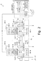
- Fig. 2 illustrates an example configuration of the information generating system 2.
- the information generating system 2 is configured to generate correlation information used for calibration.
- the information generating system 2 includes yaw drive devices 100-1 to 100-N and an information generating device 3.
- the information generating device 3 may be connected to a communication line 4.
- the communication line 4 may be a wired or wireless communication line.
- the yaw drive devices 100 for generating a yaw drive force are mounted to the nacelle 10.
- N is an integer greater than or equal to 2
- yaw drive devices 100-1 through 100-N are mounted on the nacelle 10.
- the yaw drive devices may be collectively referred to simply as "the yaw drive device 100-N" ("N" is an integer ranging from 1 to N), or as "the yaw drive devices 100.”
- a ring gear 22 is formed in the inner wall of the tower 20. The ring gear 22 meshes with pinion gears 150 of the yaw drive devices 100.
- a force such as a gust of wind may be applied to the nacelle 10, the tower 20 or the like.
- a tangential force may be generated between the ring gear 22 and the pinion gears 150.
- the tangential force is generated in the tangential direction of the gear forming surface of the ring gear 22.
- the tangential force applies a torsional stress to a speed reducing unit 164 of each of the yaw drive devices 100.
- the tangential force applies tensile and compressive stresses to the clamp (fastening unit) in each of the yaw drive devices 100.
- the ring gear 22 is provided in the tower 20, and the yaw drive devices 100 are fixedly attached to the nacelle 10, but the present embodiment is not limited to such.
- the nacelle 10 may include a gear portion corresponding to the ring gear 22, and the tower 20 may include yaw drive devices corresponding to the yaw drive devices 100.
- the yaw drive devices 100 each include, for example, a casing 110, a flange 120, a fastening bolt 130, an output shaft 140, and a pinion gear 150.
- the flange 120 is mounted to the casing 110.
- the flange 120 is connected to the nacelle 10 with the fastening bolt 130.
- a first end of the output shaft 140 is connected to the interior of the casing 110 and the flange 120.
- a second end of the output shaft 140 has the pinion gear 150 provided thereon.
- the pinion gear 150 is positioned so as to mesh with the ring gear 22.
- the pinion gear 150 is rotatable when acted upon by the drive force (drive torque) output from the output shaft 140.
- the pinion gear 150 When rotating, the pinion gear 150 causes the yaw drive device 100 to turn in a turn direction (the direction in which the device is movable, or the -X direction).
- the yaw drive device 100 in turn causes the nacelle 10 to turn in the yaw direction relative to the tower 20.
- the fastening bolt 130 (fastening unit) is presented as an example of the clamp.
- the clamp is a constituent element for fixedly attaching the yaw drive device 100 to the nacelle 10.
- the clamp is not limited to the fastening bolt 130 but may be any of other known members.
- the output shaft 140 and pinion gear 150 are presented as an example of a transmission unit.
- the transmission unit is configured to transmit a drive force (drive torque) and a braking force (braking torque) from the yaw drive device 100 to the tower 20. If the drive device is fixedly attached to the tower 20, the transmission unit is configured to transmit the force from the tower 20 to the nacelle 10.
- the yaw drive devices 100 each include a braking unit 160, a motor driving unit 162, and a speed reducing unit 164.
- the braking unit 160 (shaft braking unit) is configured to generate a braking force to be applied to the output shaft 140.
- the motor driving unit 162 is configured to generate a drive force to be applied to the output shaft 140.
- the yaw drive device 100 is configured to rotate, together with the nacelle 10, relative to the ring gear 22, when acted upon by the driving force from the motor driving unit 162.
- the braking unit 160 uses an electromagnetic action to generate a braking force, in response to a control signal fed from outside.
- the braking unit 160 operates as an electromagnetic brake for generating a braking force.
- the braking unit 160 is configured not to generate a braking force (electromagnetic braking force) while being fed with a voltage.
- the braking unit 160 is configured to generate a braking force (electromagnetic braking force) while not being fed with a voltage.
- the motor driving unit 162 uses an electromagnetic action to generate a driving force, in response to a control signal fed from outside.
- the speed reducing unit 164 is configured to reduce the rotation speed determined by the motor driving unit 162, thereby increasing the driving torque.
- the yaw drive devices 100 each include a deformation sensor 166.
- the deformation sensor 166 is presented as an example of a sensing circuit.
- the deformation sensor 166 (first deformation amount obtaining unit) is configured to detect a value (signal) determined based on the deformation of the columnar portion of the fastening bolt 130.
- the deformation sensor 166 may detect a value (signal) determined by how much the clamp of the fastening bolt 130 such as a nut is deformed. The deformation of the columnar portion of the fastening bolt 130 depends on the tangential force.
- the wind power generation device 1 includes one or more hydraulic brakes (braking units) for applying a braking force to the ring gear 22.
- the hydraulic brakes are, for example, caliper brake mechanisms.
- the hydraulic brakes each include a hydraulic brake driving unit 52 and a friction member 50.
- the hydraulic brake driving unit 52 is configured to move the friction member 50 in the Z direction shown in Fig. 2 , in response to a control signal fed from outside.
- the hydraulic brake driving unit 52 is configured to apply a braking force to the ring gear 22 by pressing the friction member 50 against the ring gear 22. This allows the hydraulic brake driving unit 52 to brake the rotation of the ring gear 22 and the pinion gear 150 relative to each other. In this way, the information generating device 3 can adjust the braking force (hydraulic brake force) applied by the hydraulic brakes to the ring gear 22.
- the hydraulic brake is released. In other words, the braking force from the hydraulic brake does not act on the ring gear 22 in the first embodiment.
- the information generating device 3 includes a storage unit 31, a communicating unit 32, a control unit 33 and an information generating unit 34. Some or all of the functional units of the information generating device 3 are implemented by a processor (computer) such as a central processing unit (CPU) executing a program(s) stored on the storage unit 31.
- the storage unit 31 is preferably formed of a non-volatile storage medium (non-transitory storage medium) such as a flash memory or a hard disk drive (HDD).
- the storage unit 31 may include a volatile storage medium such as a random access memory (RAM).
- Some or all of the functional units of the information generating device 3 may be implemented by using hardware such as a large scale integrated circuit (LSI) or an application specific integrated circuit (ASIC).
- LSI large scale integrated circuit
- ASIC application specific integrated circuit
- the storage unit 31 stores thereon correlation information.
- the correlation information indicates the correspondence between the amount of deformation experienced by the fastening bolt 130-N (clamp) and the driving or braking torque of the yaw drive device 100-N.
- the format of the correlation information is not limited to a specific format but can be, for example, a data table.
- the communicating unit 32 communicates with each of the yaw drive devices 100. For example, the communicating unit 32 obtains the value of the current fed to the motor driving unit 162-N from the current sensor of the yaw drive device 100-N. The communicating unit 32 may communicate with an external device (not shown) via the communication line 4.
- the communicating unit 32 (second deformation amount obtaining unit) communicates with the deformation sensors 166.
- the communicating unit 32 obtains the amount of deformation experienced by the fastening bolt 130-N from the deformation sensor 166-N.
- the control unit 33 controls how the yaw drive devices 100 operate via the communicating unit 32.
- the control unit 33 controls the hydraulic brake drive unit 52 via the communicating unit 32.
- the motor driving unit 162 rotates, the pinion gear 150 meshing with the ring gear 22 rotates.
- the control unit 33 rotates the motor driving unit 162 while keeping a predetermined braking force applied to brake the rotation of the turnable part of the wind power generation device 1 (wind turbine), such as the ring gear 22 or nacelle 10.
- the predetermined braking force is the electromagnetic braking force generated by the braking unit 160-N (shaft braking unit).
- the upper limit of the predetermined braking force or driving torque is less than the allowable torque for the weakest one of the stiffness of the ring gear 22 (turnable gear), the stiffness of the pinion gears 150, and the stiffness of the speed reducing units 164 or hydraulic brake driving units 52.
- the upper limit of the predetermined braking force electromagagnetic braking force
- the control unit 33 determines the braking force based on the allowable torque of the yaw drive device 100 such that the yaw drive device 100 does not break down.
- the allowable torque is determined based on the specifications of the speed reducing unit 164 connected to the motor driving unit 162.
- the control unit 33 obtains the driving torque of the motor driving unit 162 via the communicating unit 32. For example, the control unit 33 calculates the driving torque of the motor driving unit 162 based on the value of the current fed to the motor driving unit 162.
- the information generating unit 34 generates correlation information indicating the correspondence between the driving torque of the motor driving unit 162-N and the amount of deformation of the fastening bolt 130-N.
- the information generating unit 34 may record the correlation information in the storage unit 31.
- Fig. 3 is a flowchart showing, as an example, how the information generating system 2 operates.
- the control unit 33 causes the hydraulic brake driving units 52 (hydraulic brake) to stop applying the hydraulic braking force (frictional braking force) designed to brake the rotation of the ring gear 22 (step S101).
- the control unit 33 uses the yaw drive devices 100-2 to 100-N (one or more second yaw drive devices) to apply an electromagnetic braking force to brake the rotation of the pinion gears 150-2 to 150-N.
- the control unit 33 determines how many of the yaw drive devices 100 generate a braking force such that the braking force does not exceed the allowable torque. This causes the electromagnetic braking force to brake the rotation of the ring gear 22 (step S102).
- the control unit 33 rotates the motor driving unit 162-1 of the yaw drive device 100- 1 (first yaw drive device) (step S103).
- the communicating unit 32 (second deformation amount obtaining unit) obtains the amount of deformation experienced by the fastening bolt 130-1 from the deformation sensor 166-1 (step S104).
- the control unit 33 obtains, via the communicating unit 32, the driving torque of the motor driving unit 162-1 (step S105).
- the information generating unit 34 generates correlation information indicating the correspondence between the driving torque of the motor driving unit 162-1 and the amount of deformation (step S106).
- the information generating unit 34 may record the correlation information in the storage unit 31.
- the communicating unit 32 may transmit the correlation information to the communication line 4.
- the control unit 33 causes the motor driving unit 162-1 to rotate while the predetermined braking force (electromagnetic braking force) is being applied to brake the rotation of the turnable unit of the wind power generation device 1 (wind turbine), for example, the nacelle 10 or ring gear 22.
- the control unit 33 causes the fastening bolt 130-1 (clamp) to deform, which is used to fixedly attach the yaw drive device 100-1 to the nacelle 10 (target part).
- the deformation sensor 166-1 (first deformation amount obtaining unit) and communicating unit 32 (second deformation amount obtaining unit) obtain the amount of deformation experienced by the fastening bolt 130-1.
- the information generating unit 34 generates the correlation information indicating the correspondence between the driving torque of the motor driving unit 162-1 and the amount of deformation experienced when the driving torque is used to rotate the yaw drive device 100-1.
- the correlation information can be generated remotely, which indicates the correspondence between the amount of deformation experienced by the clamps (fastening units) provided to fixedly attach the yaw drive devices 100 to the nacelle 10 and the driving torque generated the yaw drive devices 100.
- the first embodiment can reduce a sudden increase in the torque of the output shaft 140, thereby preventing breakage of the yaw drive devices 100 and ring gear 22.
- the second embodiment differs from the first embodiment in that at least part of the hydraulic braking force (the braking force produced by one or more hydraulic brakes selected based on a predetermined condition from among the one or more hydraulic brakes) is applied by the friction member 50 to the ring gear 22.
- the following description of the second embodiment will be mainly focused on the difference from the first embodiment.
- the control unit 33 causes the motor driving unit 162 to rotate while a predetermined braking force is being applied to brake the rotation of the ring gear 22.
- the predetermined braking force applied to the ring gear 22 is the hydraulic braking force (frictional braking force) generated by the hydraulic brake driving unit 52.
- the upper limit of the predetermined braking force or driving torque is less than the allowable torque for the weakest one of the stiffness of the ring gear 22 (turnable gear), the stiffness of the pinion gears 150, and the stiffness of the speed reducing units 164 or hydraulic brake driving units 52.
- the upper limit of the predetermined braking force (frictional braking force) is less than the allowable torque of the pinion gears 150, which are configured to be rotated by the motor driving units 162.
- the control unit 33 determines the braking force based on the allowable torque of the yaw drive device 100 such that the yaw drive device 100 does not break down.
- Fig. 4 is a flowchart showing, as an example, how the information generating system 2 operates.
- the control unit 33 selects one or more hydraulic brake driving units 52 from among the one or more hydraulic brake driving units 52.
- the control unit 33 uses the selected hydraulic brake driving units 52 to brake the rotation of the ring gear 22. In other words, the control unit 33 uses at least part of the hydraulic brake force to brake the rotation of the ring gear 22 (step S201).
- the control unit 33 causes the yaw drive devices 100-2 to 100-N to stop applying the electromagnetic braking force (braking torque) of the braking units 160-2 to 160-N (step S202).
- the control unit 33 causes the motor driving unit 162-1 to rotate (step S203).
- the communicating unit 32 obtains the amount of deformation experienced by the fastening bolt 130-1 from the deformation sensor 166-1 (step S204).
- the control unit 33 obtains, via the communicating unit 32, the driving torque of the motor driving unit 162-1 (step S205).
- the information generating unit 34 generates the correlation information indicating the correspondence between the driving torque of the motor driving unit 162-1 and the amount of deformation (step S206).
- the information generating unit 34 may record the correlation information in the storage unit 31.
- the communicating unit 32 may transmit the correlation information to the communication line 4.
- control unit 33 selects one or more hydraulic brake driving units 52 (braking unit) from among one or more hydraulic brake driving units 52.
- the control unit 33 controls the selected hydraulic brake driving units 52.
- the information generating unit 34 generates the correlation information indicating the correspondence between the driving torque of the motor driving unit 162-1 and the amount of deformation.
- the correlation information can be generated remotely, which indicates the correspondence between the amount of deformation experienced by the fastening bolts 130 and the driving torque of the yaw drive devices 100.
- a third embodiment is different from the second embodiment in that the yaw drive devices 100-1 to 100-N rotate the pinion gears 150-1 to 150-N.
- the following description of the third embodiment will be mainly focused on the differences from the second embodiment.
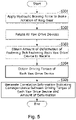
- Fig. 5 is a flowchart showing, as an example, how the information generating system 2 operates.
- the control unit 33 uses the hydraulic brake driving units 52 to apply a hydraulic braking force to brake the rotation of the ring gear 22 (step S301).
- the control unit 33 causes the motor driving units 162-1 to 162-N to rotate.
- the upper limit of the hydraulic braking force or driving torque is less than the allowable torque for the weakest one of the stiffness of the pinion gears 150, the stiffness of the ring gears 22 (turnable gear), and the stiffness of the speed reducing units 164 or hydraulic brake driving units 52.
- the communicating unit 32 obtains the amount of deformation experienced by the fastening bolts 130-1 to 130-N of the yaw drive devices 100-1 to 100-N such that the amount of deformation of each yaw drive device 100-N is obtained from the deformation sensor 166-N (step S303).
- the control unit 33 obtains, via the communicating unit 32, the driving torque of each of the yaw drive devices 100-1 to 100-N (step S304).
- the information generating unit 34 generates, for each of the yaw drive devices 100-1 to 100-N, the correlation information indicating the correspondence between the driving torque and the amount of deformation (step S305).
- the information generating unit 34 may record the correlation information in the storage unit 31.
- the communicating unit 32 may transmit the correlation information to the communication line 4.
- control unit 33 controls the hydraulic brake driving units 52 (braking unit).
- the control unit 33 causes the motor driving units 162-1 to 162-N of the yaw drive devices 100-1 to 100-N to rotate.
- the information generating unit 34 generates the correlation information indicating the correspondence between the driving torque and the amount of deformation for each of the yaw drive devices 100-1 to 100-N.
- the correlation information can be generated at once for all of the yaw drive devices 100, which indicates the correspondence between the amount of deformation experienced by the fastening bolts 130 and the driving torque of the yaw drive devices 100.
- the electromagnetic braking force (braking force) of the braking unit 160-1 is used to brake the rotation of the ring gear 22 via the pinion gear 150-1. Furthermore, the fourth embodiment is different from the first embodiment in that correlation information is generated indicating the correspondence between the electromagnetic braking force of the braking unit 160-1 and the amount of deformation of the fastening bolt 130-1. The following description of the fourth embodiment will be mainly focused on the differences from the first embodiment.
- the communicating unit 32 communicates with each of the yaw drive devices 100. For example, the communicating unit 32 obtains the value of the current fed to the braking unit 160-N from the current sensor of the yaw drive device 100-N.
- the control unit 33 controls the braking units 160.
- the control unit 33 calculates the driving torque of the braking unit 160-N based on the value of the current fed to the braking unit 160-N.
- the information generating unit 34 generates correlation information indicating the correspondence between the driving torque of the braking unit 160-N and the amount of deformation of the fastening bolt 130-N.
- Fig. 6 is a flowchart showing, as an example, how the information generating system 2 operates.
- the control unit 33 causes the hydraulic brake driving units 52 to stop applying the hydraulic braking force designed to brake the rotation of the ring gear 22 (step S401).
- the control unit 33 uses the yaw drive device 100-1 to apply an electromagnetic braking force to brake the rotation of the pinion gear 150-1 (step S402).
- the control unit 33 causes the motor driving units 162-2 to 162-N to rotate (step S403).
- the communicating unit 32 obtains the amount of deformation experienced by the fastening bolt 130-1 from the deformation sensor 166-1 (step S404).
- the control unit 33 obtains, via the communicating unit 32, the driving torque of the braking unit 160-1, in place of the driving torque of the motor driving unit 162-1 (step S405).
- the information generating unit 34 generates the correlation information indicating the correspondence between the driving torque of the braking unit 160-1 and the amount of deformation (step S406).
- the information generating unit 34 may record the correlation information in the storage unit 31.
- the communicating unit 32 may transmit the correlation information to the communication line 4.
- control unit 33 uses the yaw drive device 100-1 to apply an electromagnetic braking force to brake the rotation of the pinion gear 150-1.
- the control unit 33 causes the motor driving units 162-2 to 162-N of the yaw drive devices 100-2 to 100-N to rotate.
- the information generating unit 34 generates the correlation information indicating the correspondence between the driving torque of the braking unit 160-1 of the yaw drive device 100-1 and the amount of deformation.
- the correlation information can be generated remotely, which indicates the correspondence between the amount of deformation experienced by the fastening bolts 130 and the driving torque of the yaw drive devices 100.
- a plurality of functions are distributively provided. Some or all of the functions may be integrated. Any one of the functions may be partly or entirely segmented into a plurality of functions, which are distributively provided. Irrespective of whether or not the functions are integrated or distributed, they are acceptable as long as they are configured to solve the problems.
Landscapes
- Engineering & Computer Science (AREA)
- Life Sciences & Earth Sciences (AREA)
- Sustainable Development (AREA)
- Sustainable Energy (AREA)
- Chemical & Material Sciences (AREA)
- Combustion & Propulsion (AREA)
- Mechanical Engineering (AREA)
- General Engineering & Computer Science (AREA)
- Wind Motors (AREA)
- Details Of Spanners, Wrenches, And Screw Drivers And Accessories (AREA)
Abstract
Description
- The present disclosure relates to an information generating device, an information generating method and an information generating program.
- Wind power generation devices include nacelles. In a wind power generation device, the nacelle utilizes driving torques from one or more yaw drive devices to yaw about the tower. The wind power generation devices are required to prevent the yaw drive devices from experiencing overload.
- Patent Literature 1:
Japanese Patent Application Publication No. 2015-140777 - To prevent the yaw drive devices from experiencing overload, it is required to determine the load on the yaw drive devices. For example, the load on the yaw drive devices can be determined by determining deformation of the clamps (fastening bolts) provided to fixedly attach the yaw drive devices to the nacelle and using the determined deformation as an indicator of the load on the yaw drive devices. When the yaw drive devices generate a predetermined driving torque, the amount of deformation may vary among the clamps due to the individual differences between the yaw drive devices and other factors. If the amount of initial deformation varies among the clamps, the correspondence between the driving torque of the yaw drive devices and the amount of deformation experienced by the clamps may not be fixed while the wind power generation devices are in operation. With such variability being present, the load on the yaw drive devices can not be accurately determined based on the driving torque of the yaw drive devices. In order to know such variability in the amount of initial deformation, calibration is required. The calibration can be performed using correlation information indicating the correspondence between the amount of deformation experienced by the clamps and the driving torque of the yaw drive devices.
- The wind power generation devices (wind turbines), however, are driven and controlled only by controlling whether to drive or brake the yaw drive devices. For this reason, if one of the yaw drive devices is simply driven while the ring gear is being braked, the driven yaw drive device is overloaded. This may result in breakage of the turning power transmitting portion of the yaw drive device. Considering these, the correlation information indicating the correspondence between the driving torque of each yaw drive devices and the amount of deformation experienced by the corresponding clamp is obtained by a worker going inside the nacelle and manually rotating each yaw drive devices to measure the amount of deformation of the clamp. This approach, however, forces burden on the worker. Therefore, an alternative method is required to enable the correlation information to be obtained remotely.
- An object of the present disclosure is to provide an information generating device, an information generating method and an information generating program for remotely generating correlation information indicating the correspondence between the amount of deformation experienced by clamps provided to fixedly attach yaw drive devices to a nacelle and a driving torque produced by the yaw drive devices.
- (1) One aspect of the present disclosure provides an information generating device including a control unit for causing a motor to rotate a pinion gear meshing with a ring gear while a predetermined braking force is applied to brake rotation of a turnable part of a wind turbine, thereby causing a fastening part to deform, where the fastening part is provided to fixedly attach the motor to a target part, a deformation amount obtaining unit for obtaining an amount of deformation experienced by the fastening part, and an information generating unit for generating correlation information indicating a correspondence between a driving torque of the motor and the amount of deformation experienced when the driving torque is used to rotate the motor.
The information generating device can generate the correlation information remotely, which indicates the correspondence between the amount of deformation experienced by a clamp used to fixedly attach yaw driving devices to a nacelle (target part) and a driving torque of the yaw driving devices. - (2) In order to brake the turnable part, the control unit may control a braking unit configured to brake relative rotation of the ring gear and the pinion gear.
- (3) The motor may include a shaft braking unit for braking a rotatable shaft of the motor. The control unit may control the shaft braking unit to brake the turnable part.
- (4) An upper limit of the predetermined braking force may be less than an allowable torque for a weakest one of stiffness of the pinion gear, stiffness of the turnable part, and stiffness of a speed reducing unit of the motor.
- (5) One aspect of the present disclosure provides an information generating device including a control unit for, while a braking force of a first motor is applied to brake rotation of a turnable part of a wind turbine, causing a second motor to rotate a pinion gear meshing with a ring gear, thereby causing a fastening part to deform, where the fastening part is provided to fixedly attach the first motor to a target part, a deformation amount obtaining unit for obtaining an amount of deformation experienced by the fastening part, and an information generating unit for generating correlation information indicating a correspondence between a predetermined driving torque and the amount of deformation experienced when the predetermined driving torque is used to rotate the second motor.
- (6) An upper limit of the predetermined driving torque may be less than an allowable torque for a weakest one of stiffness of the pinion gear, stiffness of the turnable part, and stiffness of a speed reducing unit of the second motor.
- (7) One aspect of the present disclosure provides an information generating method including steps of causing a motor to rotate a pinion gear meshing with a ring gear while a predetermined braking force is applied to brake rotation of a turnable part of a wind turbine, thereby causing a fastening part to deform, where the fastening part is provided to fixedly attach the motor to a target part, obtaining an amount of deformation experienced by the fastening part, and generating correlation information indicating a correspondence between a driving torque of the motor and the amount of deformation experienced when the driving torque is used to rotate the motor.
- (8) An upper limit of the predetermined braking force may be less than an allowable torque for a weakest one of stiffness of the pinion gear, stiffness of the turnable part, and stiffness of a speed reducing unit of the motor.
- (9) One aspect of the present disclosure provides an information generating method including steps of, while a braking force of a first motor is applied to brake rotation of a turnable part of a wind turbine, causing a second motor to rotate a pinion gear meshing with a ring gear, thereby causing a fastening part to deform, where the fastening part is provided to fixedly attach the first motor to a target part, obtaining an amount of deformation experienced by the fastening part, and generating correlation information indicating a correspondence between a predetermined driving torque and the amount of deformation experienced when the predetermined driving torque is used to rotate the second motor.
- (10) An upper limit of the predetermined driving torque may be less than an allowable torque of a weakest one of stiffness of the pinion gear, stiffness of the turnable part, and stiffness of a speed reducing unit of the second motor.
- (11) One aspect of the present disclosure provides an information generating program. The information generating program causes a computer to perform procedures of causing a motor to rotate a pinion gear meshing with a ring gear while a predetermined braking force is applied to brake rotation of a turnable part of a wind turbine, thereby causing a fastening part to deform, where the fastening part is provided to fixedly attach the motor to a target part, obtaining an amount of deformation experienced by the fastening part, and generating correlation information indicating a correspondence between a driving torque of the motor and the amount of deformation experienced when the driving torque is used to rotate the motor.
- (12) An upper limit of the predetermined braking force may be less than an allowable torque for a weakest one of stiffness of the pinion gear, stiffness of the turnable part, and stiffness of a speed reducing unit of the motor.
- (13) One aspect of the present disclosure provides an information generating program. The information generating program causes a computer to perform procedures of, while a braking force of a first motor is applied to brake rotation of a turnable part of a wind turbine, causing a second motor to rotate a pinion gear meshing with a ring gear, thereby causing a fastening part to deform, where the fastening part is provided to fixedly attach the first motor to a target part, obtaining an amount of deformation experienced by the fastening part, and generating correlation information indicating a correspondence between a predetermined driving torque and the amount of deformation experienced when the predetermined driving torque is used to rotate the second motor.
- (14) An upper limit of the predetermined driving torque may be less than an allowable torque for a weakest one of stiffness of the pinion gear, stiffness of the turnable part, and stiffness of a speed reducing unit of the second motor.
- The present disclosure can generate the correlation information remotely, which indicates the correspondence between the amount of deformation experienced by the clamp used to fixedly attach the yaw driving devices to the nacelle and the driving torque of the yaw driving devices.
-
-
Fig. 1 shows an example configuration of a wind power generation device according to an embodiment of the present invention. -
Fig. 2 illustrates an example configuration of an information generating system relating to an embodiment. -
Fig. 3 is a flowchart showing, as an example, how an information generating system relating to a first embodiment operates. -
Fig. 4 is a flowchart showing, as an example, how an information generating system relating to a second embodiment operates. -
Fig. 5 is a flowchart showing, as an example, how an information generating system relating to a third embodiment operates. -
Fig. 6 is a flowchart showing, as an example, how an information generating system relating to a fourth embodiment operates. - Embodiments of the present disclosure will now be described in detail with reference to the appended drawings.
-
Fig. 1 shows an example configuration of a wind power generation device 1 . The wind power generation device 1 includes, for example, anacelle 10, atower 20,blades 30, and ahub 40. Thetower 20 andnacelle 10 are presented as an example of two structures included in the wind power generation device 1. Thetower 20 andnacelle 10 move relative to each other utilizing a force from a yaw drive device. Thetower 20 is presented as an example of a first structure. The first structure is a part of the wind power generation device 1 that is fixedly installed on a surface where the wind power generation device 1 is installed (the ground or sea surface). Thenacelle 10 is presented as an example of a second structure. The second structure is movable relative to the first structure utilizing drive forces from yaw drive devices. The second structure becomes stationary relative to the first structure when acted upon by a braking force from theyaw drive devices 100. - The
nacelle 10 is mounted on the top end (the end in the Z direction) of thetower 20. Theblades 30 are mounted to thenacelle 10 via thehub 40. Thenacelle 10 turns theblades 30 andhub 40 to adjust their orientation in the yaw direction. Thenacelle 10 has a yaw drive mechanism provided therein. The yaw drive mechanism is configured to generate a yaw drive force for causing thenacelle 10 to yaw. A yaw drive device is introduced as an example of a drive device and a wind turbine drive device. The drive device and wind turbine drive device are configured to generate a force for rotating theblades 30 andhub 40 to adjust their orientation (the orientation of the wind turbine) in accordance with the wind direction. The yaw drive device is designed to rotate theblades 30 andhub 40 to adjust their orientation (the orientation of the wind turbine) in accordance with the wind direction. Thenacelle 10 is presented as an example of a structure that is designed to receive none of the force generated by the drive device. Thetower 20 is presented as an example of a structure that is designed to receive the force generated by the drive device. - The
tower 20 is installed on land or offshore. Thetower 20 extends upward vertically from the ground or sea surface. Thenacelle 10 is mounted on the top end of thetower 20. Thetower 20 has a ring gear therein for turning thenacelle 10 in the yaw direction. - The
blades 30 are vanes for generating a rotational force when acted upon by a force of wind. In the present embodiment, threeblades 30 are provided. - The
hub 40 is mounted to thenacelle 10. Theblades 30 are mounted to thehub 40. Thehub 40 is configured to transmit to a rotatable shaft the rotational force (motive power) generated by theblades 30 when acted upon by a force of wind. Thehub 40 transmits to thenacelle 10 the rotational force via the rotatable shaft. - The
hub 40 has a pitch drive mechanism provided therein. The pitch drive mechanism is configured to generate a pitch drive force for causing theblades 30 to pitch. Eachblade 30 is provided with a pitch drive mechanism. The pitch drive mechanisms cause theblades 30 to pitch at a speed determined by the speed of the wind, to control the angle of theblades 30. - In the wind power generation device 1, the motive power generated by the rotation of the
blades 30 is transmitted from thehub 40 to a power generator (not shown) in thenacelle 10. In the wind power generation device 1, the generator converts the motive power into electric power. In this way, the wind power generation device 1 generates power from wind. - The following now describes an example configuration of an information generating system 2.
Fig. 2 illustrates an example configuration of the information generating system 2. The information generating system 2 is configured to generate correlation information used for calibration. The information generating system 2 includes yaw drive devices 100-1 to 100-N and aninformation generating device 3. Theinformation generating device 3 may be connected to a communication line 4. The communication line 4 may be a wired or wireless communication line. - The
yaw drive devices 100 for generating a yaw drive force are mounted to thenacelle 10. In the following, N ("N" is an integer greater than or equal to 2) yaw drive devices 100-1 through 100-N are mounted on thenacelle 10. In the following description, the yaw drive devices may be collectively referred to simply as "the yaw drive device 100-N" ("N" is an integer ranging from 1 to N), or as "theyaw drive devices 100." Aring gear 22 is formed in the inner wall of thetower 20. Thering gear 22 meshes with pinion gears 150 of theyaw drive devices 100. - With the
ring gear 22 and the pinion gears 150 meshing with each other, a force such as a gust of wind may be applied to thenacelle 10, thetower 20 or the like. In such a case, a tangential force may be generated between thering gear 22 and the pinion gears 150. The tangential force is generated in the tangential direction of the gear forming surface of thering gear 22. The tangential force applies a torsional stress to aspeed reducing unit 164 of each of theyaw drive devices 100. The tangential force applies tensile and compressive stresses to the clamp (fastening unit) in each of theyaw drive devices 100. In the present embodiment, thering gear 22 is provided in thetower 20, and theyaw drive devices 100 are fixedly attached to thenacelle 10, but the present embodiment is not limited to such. For example, thenacelle 10 may include a gear portion corresponding to thering gear 22, and thetower 20 may include yaw drive devices corresponding to theyaw drive devices 100. - The
yaw drive devices 100 each include, for example, acasing 110, aflange 120, afastening bolt 130, anoutput shaft 140, and apinion gear 150. Theflange 120 is mounted to thecasing 110. Theflange 120 is connected to thenacelle 10 with thefastening bolt 130. A first end of theoutput shaft 140 is connected to the interior of thecasing 110 and theflange 120. A second end of theoutput shaft 140 has thepinion gear 150 provided thereon. Thepinion gear 150 is positioned so as to mesh with thering gear 22. Thepinion gear 150 is rotatable when acted upon by the drive force (drive torque) output from theoutput shaft 140. When rotating, thepinion gear 150 causes theyaw drive device 100 to turn in a turn direction (the direction in which the device is movable, or the -X direction). Theyaw drive device 100 in turn causes thenacelle 10 to turn in the yaw direction relative to thetower 20. The fastening bolt 130 (fastening unit) is presented as an example of the clamp. The clamp is a constituent element for fixedly attaching theyaw drive device 100 to thenacelle 10. The clamp is not limited to thefastening bolt 130 but may be any of other known members. Theoutput shaft 140 andpinion gear 150 are presented as an example of a transmission unit. The transmission unit is configured to transmit a drive force (drive torque) and a braking force (braking torque) from theyaw drive device 100 to thetower 20. If the drive device is fixedly attached to thetower 20, the transmission unit is configured to transmit the force from thetower 20 to thenacelle 10. - The
yaw drive devices 100 each include abraking unit 160, amotor driving unit 162, and aspeed reducing unit 164. The braking unit 160 (shaft braking unit) is configured to generate a braking force to be applied to theoutput shaft 140. Themotor driving unit 162 is configured to generate a drive force to be applied to theoutput shaft 140. Theyaw drive device 100 is configured to rotate, together with thenacelle 10, relative to thering gear 22, when acted upon by the driving force from themotor driving unit 162. Thebraking unit 160 uses an electromagnetic action to generate a braking force, in response to a control signal fed from outside. Thebraking unit 160 operates as an electromagnetic brake for generating a braking force. For example, thebraking unit 160 is configured not to generate a braking force (electromagnetic braking force) while being fed with a voltage. For example, thebraking unit 160 is configured to generate a braking force (electromagnetic braking force) while not being fed with a voltage. Themotor driving unit 162 uses an electromagnetic action to generate a driving force, in response to a control signal fed from outside. Thespeed reducing unit 164 is configured to reduce the rotation speed determined by themotor driving unit 162, thereby increasing the driving torque. - The
yaw drive devices 100 each include adeformation sensor 166. Thedeformation sensor 166 is presented as an example of a sensing circuit. The deformation sensor 166 (first deformation amount obtaining unit) is configured to detect a value (signal) determined based on the deformation of the columnar portion of thefastening bolt 130. Thedeformation sensor 166 may detect a value (signal) determined by how much the clamp of thefastening bolt 130 such as a nut is deformed. The deformation of the columnar portion of thefastening bolt 130 depends on the tangential force. - The wind power generation device 1 includes one or more hydraulic brakes (braking units) for applying a braking force to the
ring gear 22. The hydraulic brakes are, for example, caliper brake mechanisms. The hydraulic brakes each include a hydraulicbrake driving unit 52 and afriction member 50. The hydraulicbrake driving unit 52 is configured to move thefriction member 50 in the Z direction shown inFig. 2 , in response to a control signal fed from outside. The hydraulicbrake driving unit 52 is configured to apply a braking force to thering gear 22 by pressing thefriction member 50 against thering gear 22. This allows the hydraulicbrake driving unit 52 to brake the rotation of thering gear 22 and thepinion gear 150 relative to each other. In this way, theinformation generating device 3 can adjust the braking force (hydraulic brake force) applied by the hydraulic brakes to thering gear 22. - In the first embodiment, the hydraulic brake is released. In other words, the braking force from the hydraulic brake does not act on the
ring gear 22 in the first embodiment. - The
information generating device 3 includes astorage unit 31, a communicatingunit 32, acontrol unit 33 and aninformation generating unit 34. Some or all of the functional units of theinformation generating device 3 are implemented by a processor (computer) such as a central processing unit (CPU) executing a program(s) stored on thestorage unit 31. Thestorage unit 31 is preferably formed of a non-volatile storage medium (non-transitory storage medium) such as a flash memory or a hard disk drive (HDD). Thestorage unit 31 may include a volatile storage medium such as a random access memory (RAM). Some or all of the functional units of theinformation generating device 3 may be implemented by using hardware such as a large scale integrated circuit (LSI) or an application specific integrated circuit (ASIC). - The
storage unit 31 stores thereon correlation information. The correlation information indicates the correspondence between the amount of deformation experienced by the fastening bolt 130-N (clamp) and the driving or braking torque of the yaw drive device 100-N. The format of the correlation information is not limited to a specific format but can be, for example, a data table. - The communicating
unit 32 communicates with each of theyaw drive devices 100. For example, the communicatingunit 32 obtains the value of the current fed to the motor driving unit 162-N from the current sensor of the yaw drive device 100-N.The communicating unit 32 may communicate with an external device (not shown) via the communication line 4. - The communicating unit 32 (second deformation amount obtaining unit) communicates with the
deformation sensors 166. The communicatingunit 32 obtains the amount of deformation experienced by the fastening bolt 130-N from the deformation sensor 166-N. - The
control unit 33 controls how theyaw drive devices 100 operate via the communicatingunit 32. Thecontrol unit 33 controls the hydraulicbrake drive unit 52 via the communicatingunit 32. As themotor driving unit 162 rotates, thepinion gear 150 meshing with thering gear 22 rotates. Thecontrol unit 33 rotates themotor driving unit 162 while keeping a predetermined braking force applied to brake the rotation of the turnable part of the wind power generation device 1 (wind turbine), such as thering gear 22 ornacelle 10. In the first embodiment, the predetermined braking force is the electromagnetic braking force generated by the braking unit 160-N (shaft braking unit). The upper limit of the predetermined braking force or driving torque is less than the allowable torque for the weakest one of the stiffness of the ring gear 22 (turnable gear), the stiffness of the pinion gears 150, and the stiffness of thespeed reducing units 164 or hydraulicbrake driving units 52. For example, if thepinion gear 150 has the weakest stiffness, the upper limit of the predetermined braking force (electromagnetic braking force) is less than the allowable torque of the pinion gears 150, which are configured to be rotated by themotor driving units 162. Thecontrol unit 33 determines the braking force based on the allowable torque of theyaw drive device 100 such that theyaw drive device 100 does not break down. In the following, the allowable torque is determined based on the specifications of thespeed reducing unit 164 connected to themotor driving unit 162. - The
control unit 33 obtains the driving torque of themotor driving unit 162 via the communicatingunit 32. For example, thecontrol unit 33 calculates the driving torque of themotor driving unit 162 based on the value of the current fed to themotor driving unit 162. - The
information generating unit 34 generates correlation information indicating the correspondence between the driving torque of the motor driving unit 162-N and the amount of deformation of the fastening bolt 130-N. Theinformation generating unit 34 may record the correlation information in thestorage unit 31. - The following now describes, as an example, how the information generating system 2 operates.
Fig. 3 is a flowchart showing, as an example, how the information generating system 2 operates. Thecontrol unit 33 causes the hydraulic brake driving units 52 (hydraulic brake) to stop applying the hydraulic braking force (frictional braking force) designed to brake the rotation of the ring gear 22 (step S101). Thecontrol unit 33 uses the yaw drive devices 100-2 to 100-N (one or more second yaw drive devices) to apply an electromagnetic braking force to brake the rotation of the pinion gears 150-2 to 150-N. Thecontrol unit 33 determines how many of theyaw drive devices 100 generate a braking force such that the braking force does not exceed the allowable torque. This causes the electromagnetic braking force to brake the rotation of the ring gear 22 (step S102). Thecontrol unit 33 rotates the motor driving unit 162-1 of the yaw drive device 100- 1 (first yaw drive device) (step S103). - The communicating unit 32 (second deformation amount obtaining unit) obtains the amount of deformation experienced by the fastening bolt 130-1 from the deformation sensor 166-1 (step S104). The
control unit 33 obtains, via the communicatingunit 32, the driving torque of the motor driving unit 162-1 (step S105). Theinformation generating unit 34 generates correlation information indicating the correspondence between the driving torque of the motor driving unit 162-1 and the amount of deformation (step S106). Theinformation generating unit 34 may record the correlation information in thestorage unit 31. The communicatingunit 32 may transmit the correlation information to the communication line 4. - As described above, the
control unit 33 causes the motor driving unit 162-1 to rotate while the predetermined braking force (electromagnetic braking force) is being applied to brake the rotation of the turnable unit of the wind power generation device 1 (wind turbine), for example, thenacelle 10 orring gear 22. In this manner, thecontrol unit 33 causes the fastening bolt 130-1 (clamp) to deform, which is used to fixedly attach the yaw drive device 100-1 to the nacelle 10 (target part). The deformation sensor 166-1 (first deformation amount obtaining unit) and communicating unit 32 (second deformation amount obtaining unit) obtain the amount of deformation experienced by the fastening bolt 130-1. Theinformation generating unit 34 generates the correlation information indicating the correspondence between the driving torque of the motor driving unit 162-1 and the amount of deformation experienced when the driving torque is used to rotate the yaw drive device 100-1. - In this way, the correlation information can be generated remotely, which indicates the correspondence between the amount of deformation experienced by the clamps (fastening units) provided to fixedly attach the
yaw drive devices 100 to thenacelle 10 and the driving torque generated theyaw drive devices 100. The first embodiment can reduce a sudden increase in the torque of theoutput shaft 140, thereby preventing breakage of theyaw drive devices 100 andring gear 22. - The second embodiment differs from the first embodiment in that at least part of the hydraulic braking force (the braking force produced by one or more hydraulic brakes selected based on a predetermined condition from among the one or more hydraulic brakes) is applied by the
friction member 50 to thering gear 22. The following description of the second embodiment will be mainly focused on the difference from the first embodiment. - The
control unit 33 causes themotor driving unit 162 to rotate while a predetermined braking force is being applied to brake the rotation of thering gear 22. In the second embodiment, the predetermined braking force applied to thering gear 22 is the hydraulic braking force (frictional braking force) generated by the hydraulicbrake driving unit 52. The upper limit of the predetermined braking force or driving torque is less than the allowable torque for the weakest one of the stiffness of the ring gear 22 (turnable gear), the stiffness of the pinion gears 150, and the stiffness of thespeed reducing units 164 or hydraulicbrake driving units 52. For example, if thepinion gear 150 has the weakest stiffness, the upper limit of the predetermined braking force (frictional braking force) is less than the allowable torque of the pinion gears 150, which are configured to be rotated by themotor driving units 162. Thecontrol unit 33 determines the braking force based on the allowable torque of theyaw drive device 100 such that theyaw drive device 100 does not break down. -
Fig. 4 is a flowchart showing, as an example, how the information generating system 2 operates. Thecontrol unit 33 selects one or more hydraulicbrake driving units 52 from among the one or more hydraulicbrake driving units 52. Thecontrol unit 33 uses the selected hydraulicbrake driving units 52 to brake the rotation of thering gear 22. In other words, thecontrol unit 33 uses at least part of the hydraulic brake force to brake the rotation of the ring gear 22 (step S201). Thecontrol unit 33 causes the yaw drive devices 100-2 to 100-N to stop applying the electromagnetic braking force (braking torque) of the braking units 160-2 to 160-N (step S202). - The
control unit 33 causes the motor driving unit 162-1 to rotate (step S203). The communicatingunit 32 obtains the amount of deformation experienced by the fastening bolt 130-1 from the deformation sensor 166-1 (step S204). - The
control unit 33 obtains, via the communicatingunit 32, the driving torque of the motor driving unit 162-1 (step S205). Theinformation generating unit 34 generates the correlation information indicating the correspondence between the driving torque of the motor driving unit 162-1 and the amount of deformation (step S206). Theinformation generating unit 34 may record the correlation information in thestorage unit 31. The communicatingunit 32 may transmit the correlation information to the communication line 4. - As described above, the
control unit 33 selects one or more hydraulic brake driving units 52 (braking unit) from among one or more hydraulicbrake driving units 52. Thecontrol unit 33 controls the selected hydraulicbrake driving units 52. Theinformation generating unit 34 generates the correlation information indicating the correspondence between the driving torque of the motor driving unit 162-1 and the amount of deformation. - In this way, the correlation information can be generated remotely, which indicates the correspondence between the amount of deformation experienced by the
fastening bolts 130 and the driving torque of theyaw drive devices 100. - A third embodiment is different from the second embodiment in that the yaw drive devices 100-1 to 100-N rotate the pinion gears 150-1 to 150-N. The following description of the third embodiment will be mainly focused on the differences from the second embodiment.
-
Fig. 5 is a flowchart showing, as an example, how the information generating system 2 operates. Thecontrol unit 33 uses the hydraulicbrake driving units 52 to apply a hydraulic braking force to brake the rotation of the ring gear 22 (step S301). Thecontrol unit 33 causes the motor driving units 162-1 to 162-N to rotate. The upper limit of the hydraulic braking force or driving torque is less than the allowable torque for the weakest one of the stiffness of the pinion gears 150, the stiffness of the ring gears 22 (turnable gear), and the stiffness of thespeed reducing units 164 or hydraulicbrake driving units 52. For example, if the pinion gears 150 have the weakest stiffness, the upper limit of the hydraulic braking force is less than the allowable torque of the pinion gears 150 (step S302). The communicatingunit 32 obtains the amount of deformation experienced by the fastening bolts 130-1 to 130-N of the yaw drive devices 100-1 to 100-N such that the amount of deformation of each yaw drive device 100-N is obtained from the deformation sensor 166-N (step S303). - The
control unit 33 obtains, via the communicatingunit 32, the driving torque of each of the yaw drive devices 100-1 to 100-N (step S304). Theinformation generating unit 34 generates, for each of the yaw drive devices 100-1 to 100-N, the correlation information indicating the correspondence between the driving torque and the amount of deformation (step S305). Theinformation generating unit 34 may record the correlation information in thestorage unit 31. The communicatingunit 32 may transmit the correlation information to the communication line 4. - As described above, the
control unit 33 controls the hydraulic brake driving units 52 (braking unit). Thecontrol unit 33 causes the motor driving units 162-1 to 162-N of the yaw drive devices 100-1 to 100-N to rotate. Theinformation generating unit 34 generates the correlation information indicating the correspondence between the driving torque and the amount of deformation for each of the yaw drive devices 100-1 to 100-N. - In this way, the correlation information can be generated at once for all of the
yaw drive devices 100, which indicates the correspondence between the amount of deformation experienced by thefastening bolts 130 and the driving torque of theyaw drive devices 100. - In a fourth embodiment, the electromagnetic braking force (braking force) of the braking unit 160-1 is used to brake the rotation of the
ring gear 22 via the pinion gear 150-1. Furthermore, the fourth embodiment is different from the first embodiment in that correlation information is generated indicating the correspondence between the electromagnetic braking force of the braking unit 160-1 and the amount of deformation of the fastening bolt 130-1. The following description of the fourth embodiment will be mainly focused on the differences from the first embodiment. - The communicating
unit 32 communicates with each of theyaw drive devices 100. For example, the communicatingunit 32 obtains the value of the current fed to the braking unit 160-N from the current sensor of the yaw drive device 100-N. - The
control unit 33 controls thebraking units 160. Thecontrol unit 33 calculates the driving torque of the braking unit 160-N based on the value of the current fed to the braking unit 160-N. Theinformation generating unit 34 generates correlation information indicating the correspondence between the driving torque of the braking unit 160-N and the amount of deformation of the fastening bolt 130-N. -
Fig. 6 is a flowchart showing, as an example, how the information generating system 2 operates. Thecontrol unit 33 causes the hydraulicbrake driving units 52 to stop applying the hydraulic braking force designed to brake the rotation of the ring gear 22 (step S401). Thecontrol unit 33 uses the yaw drive device 100-1 to apply an electromagnetic braking force to brake the rotation of the pinion gear 150-1 (step S402). Thecontrol unit 33 causes the motor driving units 162-2 to 162-N to rotate (step S403). - The communicating
unit 32 obtains the amount of deformation experienced by the fastening bolt 130-1 from the deformation sensor 166-1 (step S404). Thecontrol unit 33 obtains, via the communicatingunit 32, the driving torque of the braking unit 160-1, in place of the driving torque of the motor driving unit 162-1 (step S405). Theinformation generating unit 34 generates the correlation information indicating the correspondence between the driving torque of the braking unit 160-1 and the amount of deformation (step S406). Theinformation generating unit 34 may record the correlation information in thestorage unit 31. The communicatingunit 32 may transmit the correlation information to the communication line 4. - As described above, the
control unit 33 uses the yaw drive device 100-1 to apply an electromagnetic braking force to brake the rotation of the pinion gear 150-1. Thecontrol unit 33 causes the motor driving units 162-2 to 162-N of the yaw drive devices 100-2 to 100-N to rotate. Theinformation generating unit 34 generates the correlation information indicating the correspondence between the driving torque of the braking unit 160-1 of the yaw drive device 100-1 and the amount of deformation. - In this way, the correlation information can be generated remotely, which indicates the correspondence between the amount of deformation experienced by the
fastening bolts 130 and the driving torque of theyaw drive devices 100. - The foregoing embodiments disclosed herein describe a plurality of physically separate constituent parts. They may be combined into a single part, and any one of them may be divided into a plurality of physically separate constituent parts. Irrespective of whether or not the constituent parts are integrated, they are acceptable as long as they are configured to solve the problems.
- According to the foregoing embodiments disclosed herein, a plurality of functions are distributively provided. Some or all of the functions may be integrated. Any one of the functions may be partly or entirely segmented into a plurality of functions, which are distributively provided. Irrespective of whether or not the functions are integrated or distributed, they are acceptable as long as they are configured to solve the problems.
- The foregoing is the description of the embodiments of the present invention with reference to the drawings. Specific configurations are not limited to the above embodiments but include design modifications within the purport of the present invention.
-
- 1
- wind power generation device,
- 2
- information generating system
- 3
- information generating device
- 4
- communication line
- 10
- nacelle
- 20
- tower
- 22
- ring gear
- 30
- blade
- 31
- storage unit
- 32
- communicating unit
- 33
- control unit
- 34
- information generating unit
- 40
- hub
- 50
- friction member
- 52
- hydraulic brake driving unit
- 100
- yaw drive device
- 110
- casing
- 120
- flange
- 130
- fastening bolt
- 140
- output shaft
- 150
- pinion gear
- 160
- braking unit
- 162
- motor driving unit
- 164
- speed reducing unit
- 166
- deformation sensor
Claims (14)
- An information generating device (3) comprising:a control unit (33) for causing a motor (162) to rotate a pinion gear (150) meshing with a ring gear (22) while a predetermined braking force is applied to brake rotation of a turnable part of a wind turbine (1), thereby causing a fastening part (130) to deform, the fastening part (130) being provided to fixedly attach the motor (162) to a target part;a deformation amount obtaining unit (32, 166) for obtaining an amount of deformation experienced by the fastening part (130); andan information generating unit (34) for generating correlation information indicating a correspondence between a driving torque of the motor (162) and the amount of deformation experienced when the driving torque is used to rotate the motor (162).
- The information generating device (3) of claim 1, wherein, in order to brake the turnable part, the control unit (33) controls a braking unit (52) configured to brake relative rotation of the ring gear (22) and the pinion gear (150).
- The information generating device (3) of claim 1 or 2,wherein the motor (162) includes a shaft braking unit (160) for braking a rotatable shaft of the motor (162), andwherein the control unit (33) controls the shaft braking unit (160) to brake the turnable part.
- The information generating device (3) of any one of claims 1 to 3, wherein an upper limit of the predetermined braking force is less than an allowable torque for a weakest one of stiffness of the pinion gear (150), stiffness of the turnable part, and stiffness of a speed reducing unit (164) of the motor (162).
- An information generating device (3) comprising:a control unit (33) for, while a braking force of a first motor (162-1) is applied to brake rotation of a turnable part of a wind turbine (1), causing a second motor (162-2 to 162-N) to rotate a pinion gear (150) meshing with a ring gear (22), thereby causing a fastening part (130) to deform, the fastening part (130) being provided to fixedly attach the first motor (162-1) to a target part;a deformation amount obtaining unit (32, 166) for obtaining an amount of deformation experienced by the fastening part (130); andan information generating unit (34) for generating correlation information indicating a correspondence between a predetermined driving torque and the amount of deformation experienced when the predetermined driving torque is used to rotate the second motor (162-2 to 162-N).
- The information generating device (3) of claim 5, wherein an upper limit of the predetermined driving torque is less than an allowable torque for a weakest one of stiffness of the pinion gear (150), stiffness of the turnable part, and stiffness of a speed reducing unit (164) of the second motor (162-2 to 162-N).
- An information generating method comprising steps of:causing a motor (162) to rotate a pinion gear (150) meshing with a ring gear (22) while a predetermined braking force is applied to brake rotation of a turnable part of a wind turbine (1), thereby causing a fastening part (130) to deform, the fastening part (130) being provided to fixedly attach the motor (162) to a target part;obtaining an amount of deformation experienced by the fastening part (130); andgenerating correlation information indicating a correspondence between a driving torque of the motor (162) and the amount of deformation experienced when the driving torque is used to rotate the motor (162).
- The information generating method of claim 7, wherein an upper limit of the predetermined braking force is less than an allowable torque for a weakest one of stiffness of the pinion gear (150), stiffness of the turnable part, and stiffness of a speed reducing unit (164) of the motor (162).
- An information generating method comprising steps of:while a braking force of a first motor (162-1) is applied to brake rotation of a turnable part of a wind turbine (1), causing a second motor (162-2 to 162-N) to rotate a pinion gear (150) meshing with a ring gear (22), thereby causing a fastening part (130) to deform, the fastening part (130) being provided to fixedly attach the first motor (162-1) to a target part;obtaining an amount of deformation experienced by the fastening part (130); andgenerating correlation information indicating a correspondence between a predetermined driving torque and the amount of deformation experienced when the predetermined driving torque is used to rotate the second motor (162-2 to 162-N).
- The information generating method of claim 9, wherein an upper limit of the predetermined driving torque is less than an allowable torque of a weakest one of stiffness of the pinion gear (150), stiffness of the turnable part, and stiffness of a speed reducing unit (164) of the second motor (162-2 to 162-N).
- An information generating program causing a computer to perform procedures of:causing a motor (162) to rotate a pinion gear (150) meshing with a ring gear (22) while a predetermined braking force is applied to brake rotation of a turnable part of a wind turbine (1), thereby causing a fastening part (130) to deform, the fastening part (130) being provided to fixedly attach the motor (162) to a target part;obtaining an amount of deformation experienced by the fastening part (130); andgenerating correlation information indicating a correspondence between a driving torque of the motor (162) and the amount of deformation experienced when the driving torque is used to rotate the motor (162).
- The information generating program of claim 11, wherein an upper limit of the predetermined braking force is less than an allowable torque for a weakest one of stiffness of the pinion gear (150), stiffness of the turnable part, and stiffness of a speed reducing unit (164) of the motor (162).
- An information generating program causing a computer to perform procedures of:while a braking force of a first motor (162-1) is applied to brake rotation of a turnable part of a wind turbine (1), causing a second motor (162-2 to 162-N) to rotate a pinion gear (150) meshing with a ring gear (22), thereby causing a fastening part (130) to deform, the fastening part (130) being provided to fixedly attach the first motor (162-1) to a target part;obtaining an amount of deformation experienced by the fastening part (130); andgenerating correlation information indicating a correspondence between a predetermined driving torque and the amount of deformation experienced when the predetermined driving torque is used to rotate the second motor (162-2 to 162-N).
- The information generating program of claim 13, wherein an upper limit of the predetermined driving torque is less than an allowable torque for a weakest one of stiffness of the pinion gear (150), stiffness of the turnable part, and stiffness of a speed reducing unit (164) of the second motor (162-2 to 162-N).
Applications Claiming Priority (1)
| Application Number | Priority Date | Filing Date | Title |
|---|---|---|---|
| JP2021120897A JP7165789B1 (en) | 2021-07-21 | 2021-07-21 | Information generation device, information generation method and information generation program |
Publications (2)
| Publication Number | Publication Date |
|---|---|
| EP4123167A1 true EP4123167A1 (en) | 2023-01-25 |
| EP4123167B1 EP4123167B1 (en) | 2025-09-17 |
Family
ID=82655194
Family Applications (1)
| Application Number | Title | Priority Date | Filing Date |
|---|---|---|---|
| EP22185516.6A Active EP4123167B1 (en) | 2021-07-21 | 2022-07-18 | Information generating device, information generating method and information generating program |
Country Status (6)
| Country | Link |
|---|---|
| US (1) | US11959459B2 (en) |
| EP (1) | EP4123167B1 (en) |
| JP (1) | JP7165789B1 (en) |
| CN (1) | CN115681005B (en) |
| DK (1) | DK4123167T3 (en) |
| ES (1) | ES3051861T3 (en) |
Citations (5)
| Publication number | Priority date | Publication date | Assignee | Title |
|---|---|---|---|---|
| EP2402597A1 (en) * | 2010-06-29 | 2012-01-04 | Siemens Aktiengesellschaft | Wind turbine yaw system and method of controlling the same |
| KR101302671B1 (en) * | 2012-04-17 | 2013-09-03 | 주식회사 해성산전 | Durability test yaw drive and pitch drive of wind power generator |
| JP2015140777A (en) | 2014-01-30 | 2015-08-03 | 株式会社日立製作所 | Wind power generator |
| EP3483426A1 (en) * | 2016-07-08 | 2019-05-15 | Nabtesco Corporation | Windmill drive system and windmill |
| EP3550141A1 (en) * | 2016-12-05 | 2019-10-09 | Nabtesco Corporation | Windmill drive device, windmill drive device unit, and windmill |
Family Cites Families (12)
| Publication number | Priority date | Publication date | Assignee | Title |
|---|---|---|---|---|
| US5155375A (en) * | 1991-09-19 | 1992-10-13 | U.S. Windpower, Inc. | Speed control system for a variable speed wind turbine |
| EP2037119B1 (en) * | 2007-09-12 | 2011-10-26 | Siemens Aktiengesellschaft | Controller for wind turbine yaw system and method for reducing the loads acting on such a yaw system |
| AT11331U3 (en) * | 2010-01-14 | 2011-01-15 | Avl List Gmbh | METHOD AND DEVICE FOR CALIBRATING A TORQUE MEASUREMENT DEVICE |
| JP5562274B2 (en) * | 2010-03-12 | 2014-07-30 | Ntn株式会社 | Wear detection device, wind power generation apparatus including the same, and wear detection method |
| JP2013007600A (en) * | 2011-06-23 | 2013-01-10 | Nippon Gear Co Ltd | Torque sensor calibrator and calibration method |
| JP2013238281A (en) * | 2012-05-15 | 2013-11-28 | Sumitomo Heavy Ind Ltd | Control method for power transmission system of wind power generation facility and control device |
| JP2015533999A (en) * | 2012-11-09 | 2015-11-26 | ヴェスタス ウィンド システムズ エー/エス | Wind turbine yaw control system |
| JP6638475B2 (en) * | 2016-03-03 | 2020-01-29 | シンフォニアテクノロジー株式会社 | Zero setting method, evaluation device and program |
| DE102017008938A1 (en) * | 2017-09-25 | 2019-03-28 | Senvion Gmbh | Device for measuring moments of a wind turbine, method for operating a wind turbine and wind turbine |
| EP3749852B1 (en) * | 2018-03-29 | 2022-06-01 | Vestas Wind Systems A/S | Wind turbine generator and method of controlling wind turbine generator |
| EP3594491A1 (en) * | 2018-07-09 | 2020-01-15 | youWINenergy GmbH | Method to operate a wind turbine rotor and wind turbine installation arranged for performing the method |
| JP7413007B2 (en) * | 2019-12-25 | 2024-01-15 | ナブテスコ株式会社 | Wind turbine drive control device, wind turbine drive device control method, and program |
-
2021
- 2021-07-21 JP JP2021120897A patent/JP7165789B1/en active Active
-
2022
- 2022-07-18 EP EP22185516.6A patent/EP4123167B1/en active Active
- 2022-07-18 DK DK22185516.6T patent/DK4123167T3/en active
- 2022-07-18 US US17/866,857 patent/US11959459B2/en active Active
- 2022-07-18 ES ES22185516T patent/ES3051861T3/en active Active
- 2022-07-19 CN CN202210848872.8A patent/CN115681005B/en active Active
Patent Citations (5)
| Publication number | Priority date | Publication date | Assignee | Title |
|---|---|---|---|---|
| EP2402597A1 (en) * | 2010-06-29 | 2012-01-04 | Siemens Aktiengesellschaft | Wind turbine yaw system and method of controlling the same |
| KR101302671B1 (en) * | 2012-04-17 | 2013-09-03 | 주식회사 해성산전 | Durability test yaw drive and pitch drive of wind power generator |
| JP2015140777A (en) | 2014-01-30 | 2015-08-03 | 株式会社日立製作所 | Wind power generator |
| EP3483426A1 (en) * | 2016-07-08 | 2019-05-15 | Nabtesco Corporation | Windmill drive system and windmill |
| EP3550141A1 (en) * | 2016-12-05 | 2019-10-09 | Nabtesco Corporation | Windmill drive device, windmill drive device unit, and windmill |
Also Published As
| Publication number | Publication date |
|---|---|
| JP2023016526A (en) | 2023-02-02 |
| CN115681005B (en) | 2026-05-08 |
| JP7165789B1 (en) | 2022-11-04 |
| EP4123167B1 (en) | 2025-09-17 |
| DK4123167T3 (en) | 2025-09-29 |
| ES3051861T3 (en) | 2026-01-02 |
| US11959459B2 (en) | 2024-04-16 |
| CN115681005A (en) | 2023-02-03 |
| US20230027832A1 (en) | 2023-01-26 |
Similar Documents
| Publication | Publication Date | Title |
|---|---|---|
| EP2108825B1 (en) | System and method for reducing rotor loads in a wind turbine upon detection of blade-pitch failure and loss of counter-torque | |
| DK1612414T3 (en) | A method and apparatus for reducing rotorvingeudbøjninger, loads and / or toprotationshastighed | |
| EP3842634B1 (en) | Wind turbine drive control device and control method of wind turbine drive device | |
| EP2917570B1 (en) | Wind turbine yaw control systems | |
| US20180187646A1 (en) | Method of reducing loads acting on a wind turbine yaw system | |
| EP2876300B1 (en) | Methods and systems to shut down a wind turbine | |
| JP7508222B2 (en) | Wind power generation device, control method, and program | |
| EP2678556B1 (en) | A safety system for a wind turbine | |
| CN112727682B (en) | Blade vibration suppression system for wind turbines and associated methods | |
| CA2562596C (en) | Device for driving a first part of a wind energy turbine with respect to a second part of the wind energy turbine | |
| EP2438300A2 (en) | Hub-sited tower monitoring and control system for wind turbines | |
| CN114930016B (en) | Yaw management | |
| US9702342B2 (en) | Wind turbine | |
| US20180320661A1 (en) | Compact Multi-Disk Rotor Brake System for a Wind Turbine | |
| US20210317817A1 (en) | System and method for mitigating loads acting on a rotor blade of a wind turbine | |
| EP4123167B1 (en) | Information generating device, information generating method and information generating program | |
| US9920743B2 (en) | Wind turbine deceleration method and system | |
| CN118728631A (en) | Rotating unbalanced rotor hub and installing wind turbine rotor blades | |
| EP3865842A1 (en) | Fastener with sensing circuit, sensing circuit, and wind turbine drive device | |
| WO2021228337A1 (en) | Yaw system with yaw control based on control signal | |
| EP4400714A1 (en) | Braking force measuring method |
Legal Events
| Date | Code | Title | Description |
|---|---|---|---|
| PUAI | Public reference made under article 153(3) epc to a published international application that has entered the european phase |
Free format text: ORIGINAL CODE: 0009012 |
|
| STAA | Information on the status of an ep patent application or granted ep patent |
Free format text: STATUS: REQUEST FOR EXAMINATION WAS MADE |
|
| 17P | Request for examination filed |
Effective date: 20220718 |
|
| AK | Designated contracting states |
Kind code of ref document: A1 Designated state(s): AL AT BE BG CH CY CZ DE DK EE ES FI FR GB GR HR HU IE IS IT LI LT LU LV MC MK MT NL NO PL PT RO RS SE SI SK SM TR |
|
| P01 | Opt-out of the competence of the unified patent court (upc) registered |
Effective date: 20230523 |
|
| RBV | Designated contracting states (corrected) |
Designated state(s): AL AT BE BG CH CY CZ DE DK EE ES FI FR GB GR HR HU IE IS IT LI LT LU LV MC MK MT NL NO PL PT RO RS SE SI SK SM TR |
|
| REG | Reference to a national code |
Ref country code: DE Ref legal event code: R079 Free format text: PREVIOUS MAIN CLASS: F03D0007020000 Ipc: F03D0017000000 Ref country code: DE Ref legal event code: R079 Ref document number: 602022021481 Country of ref document: DE Free format text: PREVIOUS MAIN CLASS: F03D0007020000 Ipc: F03D0017000000 |
|
| GRAP | Despatch of communication of intention to grant a patent |
Free format text: ORIGINAL CODE: EPIDOSNIGR1 |
|
| STAA | Information on the status of an ep patent application or granted ep patent |
Free format text: STATUS: GRANT OF PATENT IS INTENDED |
|
| RIC1 | Information provided on ipc code assigned before grant |
Ipc: F03D 17/00 20160101AFI20250402BHEP |
|
| INTG | Intention to grant announced |
Effective date: 20250429 |
|
| GRAS | Grant fee paid |
Free format text: ORIGINAL CODE: EPIDOSNIGR3 |
|
| GRAA | (expected) grant |
Free format text: ORIGINAL CODE: 0009210 |
|
| STAA | Information on the status of an ep patent application or granted ep patent |
Free format text: STATUS: THE PATENT HAS BEEN GRANTED |
|
| AK | Designated contracting states |
Kind code of ref document: B1 Designated state(s): AL AT BE BG CH CY CZ DE DK EE ES FI FR GB GR HR HU IE IS IT LI LT LU LV MC MK MT NL NO PL PT RO RS SE SI SK SM TR |
|
| REG | Reference to a national code |
Ref country code: GB Ref legal event code: FG4D |
|
| REG | Reference to a national code |
Ref country code: DK Ref legal event code: T3 Effective date: 20250926 |
|
| REG | Reference to a national code |
Ref country code: CH Ref legal event code: EP |
|
| REG | Reference to a national code |
Ref country code: IE Ref legal event code: FG4D |
|
| REG | Reference to a national code |
Ref country code: DE Ref legal event code: R096 Ref document number: 602022021481 Country of ref document: DE |
|
| REG | Reference to a national code |
Ref country code: ES Ref legal event code: FG2A Ref document number: 3051861 Country of ref document: ES Kind code of ref document: T3 Effective date: 20260102 |
|
| PG25 | Lapsed in a contracting state [announced via postgrant information from national office to epo] |
Ref country code: NO Free format text: LAPSE BECAUSE OF FAILURE TO SUBMIT A TRANSLATION OF THE DESCRIPTION OR TO PAY THE FEE WITHIN THE PRESCRIBED TIME-LIMIT Effective date: 20251217 |
|
| REG | Reference to a national code |
Ref country code: LT Ref legal event code: MG9D |
|
| PG25 | Lapsed in a contracting state [announced via postgrant information from national office to epo] |
Ref country code: FI Free format text: LAPSE BECAUSE OF FAILURE TO SUBMIT A TRANSLATION OF THE DESCRIPTION OR TO PAY THE FEE WITHIN THE PRESCRIBED TIME-LIMIT Effective date: 20250917 |
|
| PG25 | Lapsed in a contracting state [announced via postgrant information from national office to epo] |
Ref country code: HR Free format text: LAPSE BECAUSE OF FAILURE TO SUBMIT A TRANSLATION OF THE DESCRIPTION OR TO PAY THE FEE WITHIN THE PRESCRIBED TIME-LIMIT Effective date: 20250917 |
|
| PG25 | Lapsed in a contracting state [announced via postgrant information from national office to epo] |
Ref country code: GR Free format text: LAPSE BECAUSE OF FAILURE TO SUBMIT A TRANSLATION OF THE DESCRIPTION OR TO PAY THE FEE WITHIN THE PRESCRIBED TIME-LIMIT Effective date: 20251218 |
|
| PG25 | Lapsed in a contracting state [announced via postgrant information from national office to epo] |
Ref country code: SE Free format text: LAPSE BECAUSE OF FAILURE TO SUBMIT A TRANSLATION OF THE DESCRIPTION OR TO PAY THE FEE WITHIN THE PRESCRIBED TIME-LIMIT Effective date: 20250917 |
|
| REG | Reference to a national code |
Ref country code: NL Ref legal event code: MP Effective date: 20250917 |
|
| PG25 | Lapsed in a contracting state [announced via postgrant information from national office to epo] |
Ref country code: LV Free format text: LAPSE BECAUSE OF FAILURE TO SUBMIT A TRANSLATION OF THE DESCRIPTION OR TO PAY THE FEE WITHIN THE PRESCRIBED TIME-LIMIT Effective date: 20250917 |
|
| PG25 | Lapsed in a contracting state [announced via postgrant information from national office to epo] |
Ref country code: BG Free format text: LAPSE BECAUSE OF FAILURE TO SUBMIT A TRANSLATION OF THE DESCRIPTION OR TO PAY THE FEE WITHIN THE PRESCRIBED TIME-LIMIT Effective date: 20250917 |
|
| PG25 | Lapsed in a contracting state [announced via postgrant information from national office to epo] |
Ref country code: RS Free format text: LAPSE BECAUSE OF FAILURE TO SUBMIT A TRANSLATION OF THE DESCRIPTION OR TO PAY THE FEE WITHIN THE PRESCRIBED TIME-LIMIT Effective date: 20251217 |
|
| PG25 | Lapsed in a contracting state [announced via postgrant information from national office to epo] |
Ref country code: NL Free format text: LAPSE BECAUSE OF FAILURE TO SUBMIT A TRANSLATION OF THE DESCRIPTION OR TO PAY THE FEE WITHIN THE PRESCRIBED TIME-LIMIT Effective date: 20250917 |
|
| REG | Reference to a national code |
Ref country code: AT Ref legal event code: MK05 Ref document number: 1838465 Country of ref document: AT Kind code of ref document: T Effective date: 20250917 |
|
| PG25 | Lapsed in a contracting state [announced via postgrant information from national office to epo] |
Ref country code: SM Free format text: LAPSE BECAUSE OF FAILURE TO SUBMIT A TRANSLATION OF THE DESCRIPTION OR TO PAY THE FEE WITHIN THE PRESCRIBED TIME-LIMIT Effective date: 20250917 |
|
| PG25 | Lapsed in a contracting state [announced via postgrant information from national office to epo] |
Ref country code: AT Free format text: LAPSE BECAUSE OF FAILURE TO SUBMIT A TRANSLATION OF THE DESCRIPTION OR TO PAY THE FEE WITHIN THE PRESCRIBED TIME-LIMIT Effective date: 20250917 |
|
| PG25 | Lapsed in a contracting state [announced via postgrant information from national office to epo] |
Ref country code: IT Free format text: LAPSE BECAUSE OF FAILURE TO SUBMIT A TRANSLATION OF THE DESCRIPTION OR TO PAY THE FEE WITHIN THE PRESCRIBED TIME-LIMIT Effective date: 20250917 |
|
| PG25 | Lapsed in a contracting state [announced via postgrant information from national office to epo] |
Ref country code: IS Free format text: LAPSE BECAUSE OF FAILURE TO SUBMIT A TRANSLATION OF THE DESCRIPTION OR TO PAY THE FEE WITHIN THE PRESCRIBED TIME-LIMIT Effective date: 20260117 |
|
| PG25 | Lapsed in a contracting state [announced via postgrant information from national office to epo] |
Ref country code: PT Free format text: LAPSE BECAUSE OF FAILURE TO SUBMIT A TRANSLATION OF THE DESCRIPTION OR TO PAY THE FEE WITHIN THE PRESCRIBED TIME-LIMIT Effective date: 20260119 Ref country code: CZ Free format text: LAPSE BECAUSE OF FAILURE TO SUBMIT A TRANSLATION OF THE DESCRIPTION OR TO PAY THE FEE WITHIN THE PRESCRIBED TIME-LIMIT Effective date: 20250917 |
|
| PG25 | Lapsed in a contracting state [announced via postgrant information from national office to epo] |
Ref country code: PL Free format text: LAPSE BECAUSE OF FAILURE TO SUBMIT A TRANSLATION OF THE DESCRIPTION OR TO PAY THE FEE WITHIN THE PRESCRIBED TIME-LIMIT Effective date: 20250917 |
|
| PG25 | Lapsed in a contracting state [announced via postgrant information from national office to epo] |
Ref country code: EE Free format text: LAPSE BECAUSE OF FAILURE TO SUBMIT A TRANSLATION OF THE DESCRIPTION OR TO PAY THE FEE WITHIN THE PRESCRIBED TIME-LIMIT Effective date: 20250917 Ref country code: SK Free format text: LAPSE BECAUSE OF FAILURE TO SUBMIT A TRANSLATION OF THE DESCRIPTION OR TO PAY THE FEE WITHIN THE PRESCRIBED TIME-LIMIT Effective date: 20250917 |