EP4123152B1 - Thrust reverser system latch assembly and method of operating same - Google Patents
Thrust reverser system latch assembly and method of operating same Download PDFInfo
- Publication number
- EP4123152B1 EP4123152B1 EP22186081.0A EP22186081A EP4123152B1 EP 4123152 B1 EP4123152 B1 EP 4123152B1 EP 22186081 A EP22186081 A EP 22186081A EP 4123152 B1 EP4123152 B1 EP 4123152B1
- Authority
- EP
- European Patent Office
- Prior art keywords
- latch
- latch member
- axially extending
- rotatable arms
- extended position
- Prior art date
- Legal status (The legal status is an assumption and is not a legal conclusion. Google has not performed a legal analysis and makes no representation as to the accuracy of the status listed.)
- Active
Links
Images


Classifications
-
- F—MECHANICAL ENGINEERING; LIGHTING; HEATING; WEAPONS; BLASTING
- F02—COMBUSTION ENGINES; HOT-GAS OR COMBUSTION-PRODUCT ENGINE PLANTS
- F02K—JET-PROPULSION PLANTS
- F02K1/00—Plants characterised by the form or arrangement of the jet pipe or nozzle; Jet pipes or nozzles peculiar thereto
- F02K1/54—Nozzles having means for reversing jet thrust
- F02K1/76—Control or regulation of thrust reversers
- F02K1/766—Control or regulation of thrust reversers with blocking systems or locking devices; Arrangement of locking devices for thrust reversers
-
- B—PERFORMING OPERATIONS; TRANSPORTING
- B64—AIRCRAFT; AVIATION; COSMONAUTICS
- B64D—EQUIPMENT FOR FITTING IN OR TO AIRCRAFT; FLIGHT SUITS; PARACHUTES; ARRANGEMENT OR MOUNTING OF POWER PLANTS OR PROPULSION TRANSMISSIONS IN AIRCRAFT
- B64D29/00—Power-plant nacelles, fairings or cowlings
- B64D29/06—Attaching of nacelles, fairings or cowlings
-
- B—PERFORMING OPERATIONS; TRANSPORTING
- B64—AIRCRAFT; AVIATION; COSMONAUTICS
- B64D—EQUIPMENT FOR FITTING IN OR TO AIRCRAFT; FLIGHT SUITS; PARACHUTES; ARRANGEMENT OR MOUNTING OF POWER PLANTS OR PROPULSION TRANSMISSIONS IN AIRCRAFT
- B64D29/00—Power-plant nacelles, fairings or cowlings
- B64D29/08—Inspection panels for power plants
-
- F—MECHANICAL ENGINEERING; LIGHTING; HEATING; WEAPONS; BLASTING
- F05—INDEXING SCHEMES RELATING TO ENGINES OR PUMPS IN VARIOUS SUBCLASSES OF CLASSES F01-F04
- F05D—INDEXING SCHEME FOR ASPECTS RELATING TO NON-POSITIVE-DISPLACEMENT MACHINES OR ENGINES, GAS-TURBINES OR JET-PROPULSION PLANTS
- F05D2220/00—Application
- F05D2220/30—Application in turbines
- F05D2220/32—Application in turbines in gas turbines
- F05D2220/323—Application in turbines in gas turbines for aircraft propulsion, e.g. jet engines
-
- F—MECHANICAL ENGINEERING; LIGHTING; HEATING; WEAPONS; BLASTING
- F05—INDEXING SCHEMES RELATING TO ENGINES OR PUMPS IN VARIOUS SUBCLASSES OF CLASSES F01-F04
- F05D—INDEXING SCHEME FOR ASPECTS RELATING TO NON-POSITIVE-DISPLACEMENT MACHINES OR ENGINES, GAS-TURBINES OR JET-PROPULSION PLANTS
- F05D2260/00—Function
- F05D2260/30—Retaining components in desired mutual position
-
- Y—GENERAL TAGGING OF NEW TECHNOLOGICAL DEVELOPMENTS; GENERAL TAGGING OF CROSS-SECTIONAL TECHNOLOGIES SPANNING OVER SEVERAL SECTIONS OF THE IPC; TECHNICAL SUBJECTS COVERED BY FORMER USPC CROSS-REFERENCE ART COLLECTIONS [XRACs] AND DIGESTS
- Y10—TECHNICAL SUBJECTS COVERED BY FORMER USPC
- Y10T—TECHNICAL SUBJECTS COVERED BY FORMER US CLASSIFICATION
- Y10T292/00—Closure fasteners
- Y10T292/08—Bolts
- Y10T292/0886—Sliding and swinging
Definitions
- This disclosure relates generally to gas turbine engines, and more particularly to latch assemblies for gas turbine engine thrust reversers.
- Modern aircraft may include one or more propulsion systems powered by a gas turbine engine.
- the propulsion systems may include a nacelle which houses the engine and auxiliary systems, and which provides an aerodynamic surface for flight.
- the nacelle may also form a portion of a bypass air duct between the nacelle and the engine.
- the nacelle may include a thrust reverser (e.g., a cascade-type thrust reverser) which may include an inner fixed structure (“IFS").
- the IFS may form part of the interior surface of the bypass air duct through the thrust reverser and may define a core compartment that surrounds the engine.
- a thrust reverser IFS structure may be divided into panel halves which may be held together by remote latch assemblies. Bumpers may additionally be included between the panel halves to provide a load path for hoop compression experienced by the panel halves.
- the latch assemblies may have a pin-and-socket configuration in which a pin is engaged with an opposing socket in order to place the latch assembly in a latched condition.
- pin-and-socket type latch assemblies may be susceptible to jamming between the pin and associated socket, thereby causing difficulty in the unlatching of the latch assembly during maintenance of the associated gas turbine engine. Accordingly, there is a need for improved thrust reverser latch assemblies.
- US 2020/0102909 A1 discloses a prior art latch assembly for a gas turbine engine thrust reverser system as set forth in the preamble of claim 1.
- EP 1 764 499 A1 discloses a further latch assembly.
- a latch assembly for a gas turbine engine thrust reverser system as recited in claim 1.
- FIG. 1 a perspective view of an aircraft 10 is shown in FIG. 1 .
- the aircraft 10 includes a fuselage 12 and wings 14 which extend outwardly from the fuselage 12.
- the aircraft 10 may include one or more propulsion systems which may be supported, for example, by the wings 14 of the aircraft 10.
- the propulsion systems may include a gas turbine engine such as the gas turbine engine 20 illustrated in FIGS. 1-3 .
- the gas turbine engine 20 includes a fan 22 and an engine core 24 housed within a nacelle 26 and disposed about an axial centerline 27.
- the nacelle 26 is mounted to a pylon 28 which may, for example, mount the gas turbine engine 20 to the wing 14 of the aircraft 10.
- the nacelle 26 may include an inlet 30, a fan cowl 32, a thrust reverser system 34, and an exhaust system 36.
- the nacelle surrounds the engine core 24 providing smooth aerodynamic surfaces for airflow around and into the gas turbine engine 20.
- the nacelle 26 also defines a portion of a bypass air duct through the gas turbine engine 20.
- the fan 22 may draw and direct a flow of air into and through the gas turbine engine 20.
- the air is divided into two principal flow paths, one flow path through engine core 24 (i.e., a "core airflow"), and another flow path through a bypass air duct (i.e., a "bypass airflow").
- the engine core flow path is directed into the engine core 24 and initially passes through a compressor that increases the air flow pressure, and then through a combustor where the air is mixed with fuel and ignited.
- the combustion of the fuel and air mixture causes a series of turbine blades at the rear of the engine core 24 to rotate, and to drive the engine's compressor and fan 22.
- the high-pressure exhaust gases from the combustion of the fuel and air mixture are thereafter directed through the exhaust system 36 for thrust.
- the thrust reverser system 34 may include an inner fixed structure 38 ("IPS") and a translating sleeve 40.
- the translating sleeve 40 in combination with an air diversion system (e.g., blocker doors, diversion doors, etc. - not shown) may be configured to direct airflow in the bypass duct through one or more cascade arrays 42 to create reverse thrust.
- the translating sleeve 40 may translate and/or move from a forward position (see FIG. 2 ) to an aft position (see FIG. 3 ), thereby separating the translating sleeve 40 from the fan cowl 32.
- the aft movement of the translating sleeve 40 and operation of the air diversion system causes air to be diverted from the bypass duct through the cascade arrays 38 and in a forward direction to create reverse thrust.
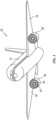
- FIGS. 4 and 5 an aft view of the thrust reverser system 34 in a closed condition is shown in FIG. 4 while an aft view of the thrust reverser system 34 in an open condition is shown in FIG. 5 .
- the thrust reverser system 34 may be split into halves, for example, a left outer panel half 44 and counterpart right outer panel half 46 of the translating sleeve 40 and a left inner panel half 48 and counterpart right inner panel half 50 of the inner fixed structure 38.
- the outer panel halves 44, 46 and the inner panel halves 48, 50 may be hinged to the pylon 28 at hinges 52 and may be hinged open in order to provide access to interior portions of the gas turbine engine 20 such as the engine core 24.
- the term "closed condition” will be used to refer to the panel halves 44, 46, 48, 50 in a fully shut position (e.g., the panel halves 44, 46, 48, 50 are positioned for flight).
- the term "open condition” will be used to refer to the panel halves 44, 46, 48, 50 in a condition other than the closed condition (e.g., the panel halves 44, 46, 48, 50 are partially open, fully open, etc.).
- the inner fixed structure 38 of the thrust reverser system 34 includes one or more remotely actuated latch assemblies 54 configured to secure the left inner panel half 48 and the right inner panel half 50 (hereinafter the "first panel half” 48 and the “second panel half” 50) together in a closed condition.
- the latch assembly 54 may be operated by an actuation system (not shown), however, the present disclosure is not limited to any particular actuation system or means for operating the latch assembly 54.
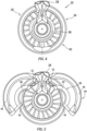
- FIGS. 6 and 7 illustrate the configuration of the latch assembly 54 with respect to a latch axis 56, with the first panel half 48 and the second panel half 50 in a closed condition.
- the latch assembly 54 includes a housing 58.
- the housing 58 includes a first housing portion 60 mounted to the first panel half 48 and a second housing portion 62 mounted to the second panel half 50.
- the first housing portion 60 may include a lateral wall 64 having an exterior surface 66 which faces the second housing portion 62 with the panel halves 48, 50 in a closed condition, and an interior surface 68 opposite the exterior surface 66.
- the first housing portion 60 may further include an aperture 70 extending along the latch axis 56 from the interior surface 68 to the exterior surface 66.
- the second housing portion 62 may include a lateral wall 72 having an exterior surface 74 which faces the first housing portion 60 with the panel halves 48, 50 in a closed condition, and an interior surface 76 opposite the exterior surface 74.
- the second housing portion 62 may further include an aperture 78 extending along the latch axis 56 from the interior surface 76 to the exterior surface 74.
- the second housing portion 62 has an interior width 80 substantially perpendicular to the latch axis 56.
- the aperture 78 has an aperture width 82 substantially perpendicular to the latch axis 56.
- the latch assembly 54 includes a first latch member 84 disposed within the first housing portion 60.
- the first latch member 84 is configured to translate or otherwise move along the latch axis 56 between a retracted position (see FIG. 6 ) and an extended position (see FIG. 7 ).
- the first latch member 84 includes a body 86 having a first end 88 and a second end 90 opposite the first end 88.
- the body 86 includes an axially extending passage 92 extending through all or at least a portion of the body 86 from the second end 90 toward the first end 88.
- the first latch member 84 includes at least two rotatable arms 94.
- Each of the rotatable arms 94 is rotatably attached to the body 86 at respective rotation joints 96.
- the rotatable arms 94 are configured to rotate about the respective rotation joints 96, located radially outside of the passage 92, between a retracted position (see FIG. 6 ) and an extended position (see FIG. 7 ).
- the rotatable arms 94 In the retracted position, the rotatable arms 94 are positioned within the body 86, for example, within a recess 98 of the body 86, or are otherwise positioned to extend along the body 86.
- the rotatable arms 94 extend outward from the body 86 in a direction away from the latch axis 56.
- the rotatable arms 94 may extend in a direction substantially perpendicular to the latch axis 56.
- the first latch member 84 including the rotatable arms 94, has a minimum width 100 substantially perpendicular to the latch axis 56.
- the minimum width 100 may be less than the aperture width 82.
- the rotatable arms 94, and hence the first latch member 84 has a maximum width 102 substantially perpendicular to the latch axis 56.
- the maximum width 102 may be greater than the aperture width 82 but less than the interior width 80.
- the rotatable arms 94 may radially overlap the interior surface 76 of the lateral wall 72.
- the body 86 has a length 103 extending from the rotatable arms 94 to the first end 88 substantially parallel to the latch axis 56.
- the first latch member 84 may include an actuation rod 104 configured to rotate the rotatable arms 94 between the retracted and extended positions.
- the actuation rod 104 may be disposed within the passage 92 and extend outward from the body 86 at the second end 90.
- the actuation rod 104 may be configured to translate or otherwise move along the latch axis 56 within the passage 92. Accordingly, the actuation rod 104 may be translated (e.g., axially translated) to rotate the rotatable arms 94 from the retracted position to the extended position or from the extended position to the retracted position.
- the actuation rod 104 may be connected to each of the rotatable arms 94 by at least one connector 106 rotatably mounted to the actuating rod 104 at a first connector end 108 and rotatably mounted to each respective rotatable arm 94 at a second connector end 110.
- the present disclosure is not limited to the above-described configuration of the actuation rod 104 to rotate the rotatable arms 94 between the retracted and extended positions, and operation of the rotatable arms 94 may be effected by other means.
- the latch assembly 54 includes a second latch member 112 disposed within the second housing portion 62.
- the second latch member 112 is configured to translate or otherwise move along the latch axis 56 between a retracted position (see FIG. 6 ) and an extended position (see FIG. 7 ).
- the second latch member 112 includes a body 114 having a first end 116 and a second end 118 opposite the first end 116.
- the body 114 includes a base portion 120 and at least one axially extending portion 122 extending from the base portion 120 toward the interior surface 76 of the lateral wall 72.
- the at least one axially extending portion 122 radially surrounds and defines a recess 124 located along the latch axis 56.
- the at least one axially extending portion 122 may include at least two axially extending portions with each of the at least two axially extending portions being circumferentially aligned with a respective rotatable arm of the rotatable arms 94.
- the recess 124 of the second latch member 112 has a recess width 128 substantially perpendicular to the latch axis 56.
- the recess width 128 may be greater than the aperture width 82 and the minimum width 100.
- the recess width 128 may be less than the maximum width 102.
- the recess 124 of the second latch member 112 also has a recess depth 130 between the first end 116 and the base portion 120, which may be substantially parallel to the latch axis 56.
- the recess depth 130 may be greater than the length 103.
- the body 114 includes an axially extending passage 126 extending through a portion of the body 114 from the second end 118 of the body 114 toward the first end 116 of the body 114.
- the passage 126 may include a first passage segment 138 extending from the second end 118 and a second passage segment 140 extending from the first passage segment 138 toward the first end 116.
- the second passage segment 140 may have a diameter 142 that is greater than a diameter 144 of the first passage segment 138.
- the second passage segment 140 may extend from a first axial segment end 146 to a second axial segment end 148 at the location where the second passage segment 140 meets the first passage segment 138.
- the second latch member 112 may include a locking pin 150.
- the locking pin 150 may be disposed within the passage 126 and extend outward from the body 114 at the second end 118.
- the locking pin 150 may be configured to translate or otherwise move along the latch axis 56 within the passage 126.
- the locking pin 150 may include a locking member 152 located at a distal end of the locking pin 150 and retained within the second passage segment 140.
- the locking member 152 may have a size and/or shape to prevent the locking member 152 from being withdrawn into the first passage segment 138.
- the second latch member 112 may include an axially extending spring 132 disposed within the second passage segment 140.
- the spring 132 has a first axial end 134 and a second axial end 136 opposite the first axial end 134.
- the first axial end 134 of the spring 132 is disposed proximate and may contact the body 114 of the second latch member 112 at the first axial segment end 146.
- the second axial end 136 of the spring 132 is disposed proximate and may contact the locking member 152 of the locking pin 150.
- the spring 132 may be configured for compression between the body 114 and the locking pin 150 and may axially bias the body 114 of the second latch member 112 in a direction away from the locking pin 150.
- the second latch member 112 may include a pin stopper 154 extending radially inward from the body 114 into the second passage segment 140.
- the pin stopper 154 may be in integral portion of the body 114 or may be a distinct component separately installed into the second passage segment 140.
- the pin stopper 154 may be located axially between first segment end 146 and the second segment end 148 of the second passage segment 140.
- the pin stopper 154 may extend around all or a portion of the interior circumference of the second passage segment 140.
- the pin stopper 154 may project radially inward into the second passage segment 140 a distance sufficient to obstruct axial movement of the locking member 152 but may not substantially impact axial compression or expansion of the spring 132.
- the pin stopper 154 may be configured to allow the locking member 152 to pass axially through the pin stopper 154, for example, through twisting engagement of the locking member 152 with the pin stopper 154.
- the present disclosure is not limited to inclusion of the above-described configuration of the passage 126, spring 132, locking pin 150, and/or pin stopper 154.
- first housing portion 60 and associated first latch member 84 are described herein as being associated with the first panel half 48 and the second housing portion 62 and associated second latch member 112 are described herein as being associated with the second panel half 50, it should be understood that the latch assembly 54 components of the present disclosure are limited to this particular configuration.
- the term "substantially" with regard to an angular relationship refers to the noted angular relationship +/- 10 degrees.
- the present disclosure includes a method 1000 for operating a latch assembly, such as the latch assembly 54.
- the latch assembly 54 may initially be in an "unlatched condition" with each of the first latch member 84, the rotatable arms 94, and the second latch member 112 in their respective retracted positions as shown, for example, in FIG. 8A .
- the first and second panel halves 48, 50 may be in a closed condition so that the first housing portion 60 is positioned adjacent the second housing portion 62 along the latch axis 56.
- the method 1000 includes translating the first latch member 84 along the latch axis 56 from the retracted position to the extended position (see FIGS. 9A and 9B ).
- the first latch member 84 may extend through the apertures 70, 78 of the respective first housing portion 60 and second housing portion 62.
- the rotatable arms 94 may be located axially within the second housing portion 62.
- the method 1000 includes rotating the rotatable arms 94 from the retracted position to the extended position (see FIGS. 9B and 9C ).
- the rotatable arms 94 may be rotated from the retracted position to the extended position by operation of the actuation rod 104. Insertion of the actuation rod 104 into the body 86 causes the connectors 106 about the respective first connector end 108 and second connector end 110, thereby causing the rotatable arms 94 to rotate in a counterclockwise direction from the retracted position to the extended position.
- the method 1000 includes translating the second latch member 112 along the latch axis 56 from the retracted position to the extended position (see FIGS. 9C and 9D ).
- the second latch member 112 may be axially spaced from the rotatable arms 94 of the first latch member 84.
- the first latch member 84 and the rotatable arms 94 in their respective extended positions, translation of the second latch member 112 from the retracted position to the extended position will cause the axially extending portions 122 of the second latch member 112 to contact the rotatable arms 94 of the first latch member 84.
- the rotatable arms 94 may be in contact with and fixed between the axially extending portions 122 of the second latch member 112 and the interior surface 76 of the lateral wall 72 of the second housing portion 62, as shown in FIG. 9D .
- continued axial translation of the second latch member 112 toward the first latch member 84 may cause compression of the spring 132 between the body 114 and the locking pin 150.
- Axial force from the compression of the spring 132 may aid in establishing a desired preload between the first and second latch members 84, 112.
- the latch assembly 54 of the present disclosure effects latching, in part, by locking abutting surfaces (e.g., fixing the rotatable arms 94 between the second housing portion 62 and the second latch member 112), and thereby substantially reduces or eliminates the likelihood of jamming in comparison to conventional thrust reverser pin-and-socket latch assemblies of which we are aware.
- the configuration of the latch members 84, 112 for translation and abutment along the latch axis 56 allows the latch assembly 54 to effectively resist both tension loads and compressive loads on the panel halves 48, 50 during operation of the gas turbine engine 20.
- the method 1000 may additionally include "locking" the axial position of the second latch member 112.
- the axial position of the second latch member 112 may be locked by, for example, engaging the locking pin 150 with the pin stopper 154.
- the locking pin 150 may be used axially translated along the latch axis 56 in a direction toward the first latch member 84, thereby causing the second latch member 112 to engage the first latch member 84 as described above with respect to step 1006. Continued axial translation of the locking pin 150 may cause compression of the spring 132 until the locking member 152 of the locking pin 150 contacts the pin stopper 154.
- rotation of the locking pin 150 may cause the locking member 152 to become fixedly engaged with the pin stopper 154, thereby locking the axial position of the second latch member 112.
- rotation of the locking pin 150 may cause the locking member 152 to pass axially through the pin stopper 154 where the pin stopper 154 may then prevent or otherwise obstruct axial withdrawal of the locking member 152.
- the present disclosure is not limited to any particular form of engagement between the locking member 152 and the pin stopper 154.
- the compressed condition of the spring 132 may still allow some limited axial movement of the second latch member 112 and may still aid in establishing a desired preload between the first and second latch members 84, 112.
- the steps of method 1000 described above and as illustrated in FIGS. 8A-B and 9A-D may be performed in a substantially reverse order.
- the terms “comprises”, “comprising”, or any other variation thereof, are intended to cover a non-exclusive inclusion, such that a process, method, article, or apparatus that comprises a list of elements does not include only those elements but may include other elements not expressly listed or inherent to such process, method, article, or apparatus.
Landscapes
- Engineering & Computer Science (AREA)
- Chemical & Material Sciences (AREA)
- Combustion & Propulsion (AREA)
- Mechanical Engineering (AREA)
- General Engineering & Computer Science (AREA)
- Aviation & Aerospace Engineering (AREA)
- Mutual Connection Of Rods And Tubes (AREA)
- Structures Of Non-Positive Displacement Pumps (AREA)
- Pivots And Pivotal Connections (AREA)
Description
- This disclosure relates generally to gas turbine engines, and more particularly to latch assemblies for gas turbine engine thrust reversers.
- Modern aircraft may include one or more propulsion systems powered by a gas turbine engine. The propulsion systems may include a nacelle which houses the engine and auxiliary systems, and which provides an aerodynamic surface for flight. The nacelle may also form a portion of a bypass air duct between the nacelle and the engine. In some cases, the nacelle may include a thrust reverser (e.g., a cascade-type thrust reverser) which may include an inner fixed structure ("IFS"). The IFS may form part of the interior surface of the bypass air duct through the thrust reverser and may define a core compartment that surrounds the engine.
- A thrust reverser IFS structure may be divided into panel halves which may be held together by remote latch assemblies. Bumpers may additionally be included between the panel halves to provide a load path for hoop compression experienced by the panel halves. In some thrust reversers, the latch assemblies may have a pin-and-socket configuration in which a pin is engaged with an opposing socket in order to place the latch assembly in a latched condition. However, pin-and-socket type latch assemblies may be susceptible to jamming between the pin and associated socket, thereby causing difficulty in the unlatching of the latch assembly during maintenance of the associated gas turbine engine. Accordingly, there is a need for improved thrust reverser latch assemblies.
-
US 2020/0102909 A1 discloses a prior art latch assembly for a gas turbine engine thrust reverser system as set forth in the preamble of claim 1.EP 1 764 499 A1 discloses a further latch assembly. - According to an aspect of the present disclosure, there is provided a latch assembly for a gas turbine engine thrust reverser system as recited in claim 1.
- There is also provided a thrust reverser system for a gas turbine engine as recited in claim 11.
- There is also provided a method for operating a latch assembly for a gas turbine engine thrust reverser system as recited in
claim 12. - Features of embodiments are set forth in the dependent claims.
- The present disclosure, and all its aspects, embodiments and advantages associated therewith will become more readily apparent in view of the detailed description provided below, including the accompanying drawings.
-
-
FIG. 1 illustrates a perspective view of an aircraft, in accordance with one or more embodiments of the present disclosure. -
FIG. 2 illustrates a perspective view of a gas turbine engine including a thrust reverser, in accordance with one or more embodiments of the present disclosure. -
FIG. 3 illustrates a side view of the gas turbine engine ofFIG. 2 with a translating sleeve of the thrust reverser in an aft position, in accordance with one or more embodiments of the present disclosure. -
FIG. 4 illustrates a rear, cross-sectional view of the gas turbine engine ofFIG. 2 including first and second panel halves of the thrust reverser in a closed condition, in accordance with one or more embodiments of the present disclosure. -
FIG. 5 illustrates a rear, cross-sectional view of the gas turbine engine ofFIG. 2 with the first and second panel halves of the thrust reverser in an open condition, in accordance with one or more embodiments of the present disclosure. -
FIG. 6 illustrates a view of a thrust reverser latch assembly in a fully unlatched condition, in accordance with one or more embodiments of the present disclosure. -
FIG. 7 illustrates a view of the thrust reverser latch assembly ofFIG. 6 in a fully latched condition, in accordance with one or more embodiments of the present disclosure. -
FIGS. 8A-B illustrate a portion of the thrust reverser latch assembly ofFIG. 6 , in accordance with one or more embodiments of the present disclosure. -
FIGS. 9A-D illustrate an exemplary sequence for positioning the thrust reverser latch assembly ofFIG. 6 in a fully latched condition, in accordance with one or more embodiments of the present disclosure. -
FIG. 10 illustrates a flowchart depicting a method for operating a thrust reverser latch assembly, in accordance with one or more embodiments of the present disclosure. - Referring to
FIGS. 1-3 , a perspective view of anaircraft 10 is shown inFIG. 1 . Theaircraft 10 includes afuselage 12 andwings 14 which extend outwardly from thefuselage 12. Theaircraft 10 may include one or more propulsion systems which may be supported, for example, by thewings 14 of theaircraft 10. The propulsion systems may include a gas turbine engine such as thegas turbine engine 20 illustrated inFIGS. 1-3 . - The
gas turbine engine 20 includes afan 22 and anengine core 24 housed within anacelle 26 and disposed about anaxial centerline 27. Thenacelle 26 is mounted to apylon 28 which may, for example, mount thegas turbine engine 20 to thewing 14 of theaircraft 10. Thenacelle 26 may include aninlet 30, afan cowl 32, athrust reverser system 34, and anexhaust system 36. The nacelle surrounds theengine core 24 providing smooth aerodynamic surfaces for airflow around and into thegas turbine engine 20. Thenacelle 26 also defines a portion of a bypass air duct through thegas turbine engine 20. - In various embodiments, the
fan 22 may draw and direct a flow of air into and through thegas turbine engine 20. After thefan 22, the air is divided into two principal flow paths, one flow path through engine core 24 (i.e., a "core airflow"), and another flow path through a bypass air duct (i.e., a "bypass airflow"). The engine core flow path is directed into theengine core 24 and initially passes through a compressor that increases the air flow pressure, and then through a combustor where the air is mixed with fuel and ignited. The combustion of the fuel and air mixture causes a series of turbine blades at the rear of theengine core 24 to rotate, and to drive the engine's compressor andfan 22. The high-pressure exhaust gases from the combustion of the fuel and air mixture are thereafter directed through theexhaust system 36 for thrust. - Referring to
FIGS. 2-5 , thethrust reverser system 34 may include an inner fixed structure 38 ("IPS") and atranslating sleeve 40. The translatingsleeve 40 in combination with an air diversion system (e.g., blocker doors, diversion doors, etc. - not shown) may be configured to direct airflow in the bypass duct through one ormore cascade arrays 42 to create reverse thrust. The translatingsleeve 40 may translate and/or move from a forward position (seeFIG. 2 ) to an aft position (seeFIG. 3 ), thereby separating the translatingsleeve 40 from thefan cowl 32. The aft movement of the translatingsleeve 40 and operation of the air diversion system causes air to be diverted from the bypass duct through thecascade arrays 38 and in a forward direction to create reverse thrust. - Referring to
FIGS. 4 and 5 , an aft view of thethrust reverser system 34 in a closed condition is shown inFIG. 4 while an aft view of thethrust reverser system 34 in an open condition is shown inFIG. 5 . Thethrust reverser system 34 may be split into halves, for example, a leftouter panel half 44 and counterpart rightouter panel half 46 of the translatingsleeve 40 and a leftinner panel half 48 and counterpart rightinner panel half 50 of the inner fixedstructure 38. Theouter panel halves inner panel halves pylon 28 athinges 52 and may be hinged open in order to provide access to interior portions of thegas turbine engine 20 such as theengine core 24. As used herein, the term "closed condition" will be used to refer to thepanel halves panel halves panel halves panel halves - Referring to
FIGS. 4-7 , the innerfixed structure 38 of thethrust reverser system 34 includes one or more remotely actuatedlatch assemblies 54 configured to secure the leftinner panel half 48 and the right inner panel half 50 (hereinafter the "first panel half" 48 and the "second panel half" 50) together in a closed condition. Thelatch assembly 54 may be operated by an actuation system (not shown), however, the present disclosure is not limited to any particular actuation system or means for operating thelatch assembly 54.FIGS. 6 and 7 illustrate the configuration of thelatch assembly 54 with respect to alatch axis 56, with thefirst panel half 48 and thesecond panel half 50 in a closed condition. - Referring to
FIGS. 6 and 7 , thelatch assembly 54 includes a housing 58. The housing 58 includes afirst housing portion 60 mounted to thefirst panel half 48 and asecond housing portion 62 mounted to thesecond panel half 50. Thefirst housing portion 60 may include alateral wall 64 having anexterior surface 66 which faces thesecond housing portion 62 with the panel halves 48, 50 in a closed condition, and aninterior surface 68 opposite theexterior surface 66. Thefirst housing portion 60 may further include anaperture 70 extending along thelatch axis 56 from theinterior surface 68 to theexterior surface 66. Similarly, thesecond housing portion 62 may include alateral wall 72 having anexterior surface 74 which faces thefirst housing portion 60 with the panel halves 48, 50 in a closed condition, and aninterior surface 76 opposite theexterior surface 74. Thesecond housing portion 62 may further include anaperture 78 extending along thelatch axis 56 from theinterior surface 76 to theexterior surface 74. Thesecond housing portion 62 has aninterior width 80 substantially perpendicular to thelatch axis 56. Theaperture 78 has anaperture width 82 substantially perpendicular to thelatch axis 56. - The
latch assembly 54 includes afirst latch member 84 disposed within thefirst housing portion 60. Thefirst latch member 84 is configured to translate or otherwise move along thelatch axis 56 between a retracted position (seeFIG. 6 ) and an extended position (seeFIG. 7 ). Thefirst latch member 84 includes abody 86 having afirst end 88 and asecond end 90 opposite thefirst end 88. In various embodiments, thebody 86 includes anaxially extending passage 92 extending through all or at least a portion of thebody 86 from thesecond end 90 toward thefirst end 88. - The
first latch member 84 includes at least tworotatable arms 94. Each of therotatable arms 94 is rotatably attached to thebody 86 at respective rotation joints 96. Therotatable arms 94 are configured to rotate about the respective rotation joints 96, located radially outside of thepassage 92, between a retracted position (seeFIG. 6 ) and an extended position (seeFIG. 7 ). In the retracted position, therotatable arms 94 are positioned within thebody 86, for example, within arecess 98 of thebody 86, or are otherwise positioned to extend along thebody 86. In the extended position, therotatable arms 94 extend outward from thebody 86 in a direction away from thelatch axis 56. For example, in the extended position, therotatable arms 94 may extend in a direction substantially perpendicular to thelatch axis 56. With therotatable arms 94 in the retracted position, thefirst latch member 84, including therotatable arms 94, has aminimum width 100 substantially perpendicular to thelatch axis 56. Theminimum width 100 may be less than theaperture width 82. With therotatable arms 94 in the extended position, therotatable arms 94, and hence thefirst latch member 84, has amaximum width 102 substantially perpendicular to thelatch axis 56. Themaximum width 102 may be greater than theaperture width 82 but less than theinterior width 80. Accordingly, with therotatable arms 94 in the extended position, therotatable arms 94 may radially overlap theinterior surface 76 of thelateral wall 72. With therotatable arms 94 in the extended position, thebody 86 has alength 103 extending from therotatable arms 94 to thefirst end 88 substantially parallel to thelatch axis 56. - In various embodiments, the
first latch member 84 may include anactuation rod 104 configured to rotate therotatable arms 94 between the retracted and extended positions. Theactuation rod 104 may be disposed within thepassage 92 and extend outward from thebody 86 at thesecond end 90. Theactuation rod 104 may be configured to translate or otherwise move along thelatch axis 56 within thepassage 92. Accordingly, theactuation rod 104 may be translated (e.g., axially translated) to rotate therotatable arms 94 from the retracted position to the extended position or from the extended position to the retracted position. Theactuation rod 104 may be connected to each of therotatable arms 94 by at least oneconnector 106 rotatably mounted to theactuating rod 104 at afirst connector end 108 and rotatably mounted to each respectiverotatable arm 94 at asecond connector end 110. The present disclosure is not limited to the above-described configuration of theactuation rod 104 to rotate therotatable arms 94 between the retracted and extended positions, and operation of therotatable arms 94 may be effected by other means. - The
latch assembly 54 includes asecond latch member 112 disposed within thesecond housing portion 62. Thesecond latch member 112 is configured to translate or otherwise move along thelatch axis 56 between a retracted position (seeFIG. 6 ) and an extended position (seeFIG. 7 ). Thesecond latch member 112 includes abody 114 having afirst end 116 and asecond end 118 opposite thefirst end 116. Thebody 114 includes abase portion 120 and at least one axially extendingportion 122 extending from thebase portion 120 toward theinterior surface 76 of thelateral wall 72. The at least one axially extendingportion 122 radially surrounds and defines arecess 124 located along thelatch axis 56. In various embodiments, the at least one axially extendingportion 122 may include at least two axially extending portions with each of the at least two axially extending portions being circumferentially aligned with a respective rotatable arm of therotatable arms 94. However, the present disclosure is not limited to this particular configuration of the at least one axially extendingportion 122. Therecess 124 of thesecond latch member 112 has arecess width 128 substantially perpendicular to thelatch axis 56. Therecess width 128 may be greater than theaperture width 82 and theminimum width 100. Therecess width 128 may be less than themaximum width 102. Therecess 124 of thesecond latch member 112 also has arecess depth 130 between thefirst end 116 and thebase portion 120, which may be substantially parallel to thelatch axis 56. Therecess depth 130 may be greater than thelength 103. - Referring to
FIGS. 6, 7 , and8A-B , in various embodiments, thebody 114 includes anaxially extending passage 126 extending through a portion of thebody 114 from thesecond end 118 of thebody 114 toward thefirst end 116 of thebody 114. Thepassage 126 may include afirst passage segment 138 extending from thesecond end 118 and asecond passage segment 140 extending from thefirst passage segment 138 toward thefirst end 116. In various embodiments, thesecond passage segment 140 may have adiameter 142 that is greater than adiameter 144 of thefirst passage segment 138. Thesecond passage segment 140 may extend from a firstaxial segment end 146 to a secondaxial segment end 148 at the location where thesecond passage segment 140 meets thefirst passage segment 138. - In various embodiments, the
second latch member 112 may include alocking pin 150. Thelocking pin 150 may be disposed within thepassage 126 and extend outward from thebody 114 at thesecond end 118. Thelocking pin 150 may be configured to translate or otherwise move along thelatch axis 56 within thepassage 126. Thelocking pin 150 may include a lockingmember 152 located at a distal end of thelocking pin 150 and retained within thesecond passage segment 140. The lockingmember 152 may have a size and/or shape to prevent the lockingmember 152 from being withdrawn into thefirst passage segment 138. - In various embodiments, the
second latch member 112 may include anaxially extending spring 132 disposed within thesecond passage segment 140. Thespring 132 has a firstaxial end 134 and a secondaxial end 136 opposite the firstaxial end 134. The firstaxial end 134 of thespring 132 is disposed proximate and may contact thebody 114 of thesecond latch member 112 at the firstaxial segment end 146. The secondaxial end 136 of thespring 132 is disposed proximate and may contact the lockingmember 152 of thelocking pin 150. Accordingly, thespring 132 may be configured for compression between thebody 114 and thelocking pin 150 and may axially bias thebody 114 of thesecond latch member 112 in a direction away from the lockingpin 150. - In various embodiments, the
second latch member 112 may include apin stopper 154 extending radially inward from thebody 114 into thesecond passage segment 140. Thepin stopper 154 may be in integral portion of thebody 114 or may be a distinct component separately installed into thesecond passage segment 140. Thepin stopper 154 may be located axially betweenfirst segment end 146 and thesecond segment end 148 of thesecond passage segment 140. Thepin stopper 154 may extend around all or a portion of the interior circumference of thesecond passage segment 140. Thepin stopper 154 may project radially inward into the second passage segment 140 a distance sufficient to obstruct axial movement of the lockingmember 152 but may not substantially impact axial compression or expansion of thespring 132. In various embodiments, thepin stopper 154 may be configured to allow the lockingmember 152 to pass axially through thepin stopper 154, for example, through twisting engagement of the lockingmember 152 with thepin stopper 154. The present disclosure is not limited to inclusion of the above-described configuration of thepassage 126,spring 132, lockingpin 150, and/orpin stopper 154. - While the
first housing portion 60 and associatedfirst latch member 84 are described herein as being associated with thefirst panel half 48 and thesecond housing portion 62 and associatedsecond latch member 112 are described herein as being associated with thesecond panel half 50, it should be understood that thelatch assembly 54 components of the present disclosure are limited to this particular configuration. As used herein, the term "substantially" with regard to an angular relationship refers to the noted angular relationship +/- 10 degrees. - Referring to
FIGS. 4, 5 ,8A-B ,9A-D , and10 , the present disclosure includes amethod 1000 for operating a latch assembly, such as thelatch assembly 54. Thelatch assembly 54 may initially be in an "unlatched condition" with each of thefirst latch member 84, therotatable arms 94, and thesecond latch member 112 in their respective retracted positions as shown, for example, inFIG. 8A . The first and second panel halves 48, 50 may be in a closed condition so that thefirst housing portion 60 is positioned adjacent thesecond housing portion 62 along thelatch axis 56. - In
step 1002, themethod 1000 includes translating thefirst latch member 84 along thelatch axis 56 from the retracted position to the extended position (seeFIGS. 9A and 9B ). In the extended position, thefirst latch member 84 may extend through theapertures first housing portion 60 andsecond housing portion 62. With thefirst latch member 84 in the extended position, therotatable arms 94 may be located axially within thesecond housing portion 62. - In
step 1004, themethod 1000 includes rotating therotatable arms 94 from the retracted position to the extended position (seeFIGS. 9B and 9C ). In various embodiments, for example, therotatable arms 94 may be rotated from the retracted position to the extended position by operation of theactuation rod 104. Insertion of theactuation rod 104 into thebody 86 causes theconnectors 106 about the respectivefirst connector end 108 andsecond connector end 110, thereby causing therotatable arms 94 to rotate in a counterclockwise direction from the retracted position to the extended position. - In
step 1006, themethod 1000 includes translating thesecond latch member 112 along thelatch axis 56 from the retracted position to the extended position (seeFIGS. 9C and 9D ). In the retracted position, thesecond latch member 112 may be axially spaced from therotatable arms 94 of thefirst latch member 84. With thefirst latch member 84 and therotatable arms 94 in their respective extended positions, translation of thesecond latch member 112 from the retracted position to the extended position will cause theaxially extending portions 122 of thesecond latch member 112 to contact therotatable arms 94 of thefirst latch member 84. Thus, therotatable arms 94 may be in contact with and fixed between the axially extendingportions 122 of thesecond latch member 112 and theinterior surface 76 of thelateral wall 72 of thesecond housing portion 62, as shown inFIG. 9D . In various embodiments, such as those embodiments including thespring 132, continued axial translation of thesecond latch member 112 toward thefirst latch member 84 may cause compression of thespring 132 between thebody 114 and thelocking pin 150. Axial force from the compression of thespring 132 may aid in establishing a desired preload between the first andsecond latch members rotatable arms 94 in contact with and fixed between the axially extendingportions 122 of thesecond latch member 112 and theinterior surface 76 of thelateral wall 72, thelatch assembly 54 may be considered to be in a "latched condition." - The
latch assembly 54 of the present disclosure effects latching, in part, by locking abutting surfaces (e.g., fixing therotatable arms 94 between thesecond housing portion 62 and the second latch member 112), and thereby substantially reduces or eliminates the likelihood of jamming in comparison to conventional thrust reverser pin-and-socket latch assemblies of which we are aware. Moreover, the configuration of thelatch members latch axis 56 allows thelatch assembly 54 to effectively resist both tension loads and compressive loads on the panel halves 48, 50 during operation of thegas turbine engine 20. - In
step 1008, in various embodiments, themethod 1000 may additionally include "locking" the axial position of thesecond latch member 112. In various embodiments, the axial position of thesecond latch member 112 may be locked by, for example, engaging thelocking pin 150 with thepin stopper 154. For example, the lockingpin 150 may be used axially translated along thelatch axis 56 in a direction toward thefirst latch member 84, thereby causing thesecond latch member 112 to engage thefirst latch member 84 as described above with respect to step 1006. Continued axial translation of thelocking pin 150 may cause compression of thespring 132 until the lockingmember 152 of thelocking pin 150 contacts thepin stopper 154. With the lockingmember 152 in contact with thepin stopper 154, rotation of thelocking pin 150 may cause the lockingmember 152 to become fixedly engaged with thepin stopper 154, thereby locking the axial position of thesecond latch member 112. Alternatively, rotation of thelocking pin 150 may cause the lockingmember 152 to pass axially through thepin stopper 154 where thepin stopper 154 may then prevent or otherwise obstruct axial withdrawal of the lockingmember 152. The present disclosure is not limited to any particular form of engagement between the lockingmember 152 and thepin stopper 154. With the axial position of thesecond latch member 112 locked, it should be understood that the compressed condition of thespring 132 may still allow some limited axial movement of thesecond latch member 112 and may still aid in establishing a desired preload between the first andsecond latch members - To unlock the axial position of the
second latch member 112 or to place thelatch assembly 54 in an unlatched condition, the steps ofmethod 1000 described above and as illustrated inFIGS. 8A-B and9A-D may be performed in a substantially reverse order. - It is noted that various connections are set forth between elements in the preceding description and in the drawings. It is noted that these connections are general and, unless specified otherwise, may be direct or indirect and that this specification is not intended to be limiting in this respect. A coupling between two or more entities may refer to a direct connection or an indirect connection. An indirect connection may incorporate one or more intervening entities. It is further noted that various method or process steps for embodiments of the present disclosure are described in the following description and drawings. The description may present the method and/or process steps as a particular sequence. However, to the extent that the method or process does not rely on the particular order of steps set forth herein, the method or process should not be limited to the particular sequence of steps described. As one of ordinary skill in the art would appreciate, other sequences of steps may be possible. Therefore, the particular order of the steps set forth in the description should not be construed as a limitation.
- As used herein, the terms "comprises", "comprising", or any other variation thereof, are intended to cover a non-exclusive inclusion, such that a process, method, article, or apparatus that comprises a list of elements does not include only those elements but may include other elements not expressly listed or inherent to such process, method, article, or apparatus.
- While various aspects of the present disclosure have been disclosed, it will be apparent to those of ordinary skill in the art that many more embodiments and implementations are possible within the scope of the present disclosure. For example, the present disclosure as described herein includes several aspects and embodiments that include particular features. Although these particular features may be described individually, it is within the scope of the present disclosure that some or all of these features may be combined with any one of the aspects and remain within the scope of the present disclosure. References to "various embodiments," "one embodiment," "an embodiment," "an example embodiment," etc., indicate that the embodiment described may include a particular feature, structure, or characteristic, but every embodiment may not necessarily include the particular feature, structure, or characteristic. Moreover, such phrases are not necessarily referring to the same embodiment. Further, when a particular feature, structure, or characteristic is described in connection with an embodiment, it is submitted that it is within the knowledge of one skilled in the art to effect such feature, structure, or characteristic in connection with other embodiments whether or not explicitly described. Accordingly, the present disclosure is not to be restricted except in light of the attached claims.
Claims (14)
- A latch assembly (54) for a gas turbine engine thrust reverser system (34), comprising:a housing (58) including a first housing portion (60) including a first aperture (70) and a second housing portion (62) including a second aperture (78), the second aperture (78) extending along a latch axis (56), the second housing portion (62) comprising a lateral wall (72) defining the second aperture (78), the lateral wall (72) including an exterior surface (74) facing the first housing portion (60) and an interior surface (76) facing away from the first housing portion (60); anda first latch member (84) including at least two rotatable arms (94) configured to rotate between an arm retracted position and an arm extended position in which the at least two rotatable arms (94) extend in a first direction away from the latch axis (56);characterized in further comprising:a second latch member (112) disposed within the second housing portion (62) and including a second latch member body (114) including a base portion (120) and at least one axially extending portion (122) extending from the base portion (120) in a second direction toward the interior surface (76) of the lateral wall (72), the at least one axially extending portion (122) radially surrounding a recess (124) located along the latch axis (56),whereinthe first aperture (70) extends along the latch axis (56);the first latch member is disposed within the first housing portion (60);the first latch member (84) is configured to translate along the latch axis (56) between a first retracted position with the at least two rotatable arms (94) located within the first housing portion (60) and a first extended position with the at least two rotatable arms (94) located within the second housing portion (62), wherein the first latch member (84) extends through the first aperture (70) and the second aperture (78) in the first extended position; andwith the first latch member (84) in the first extended position and the at least two rotatable arms (94) in the arm extended position, the second latch member (112) is configured to translate along the latch axis (56) between a second retracted position with the at least one axially extending portion (122) axially spaced from the at least two rotatable arms (94) and a second extended position with the at least two rotatable arms (94) in contact with and fixed between the at least one axially extending portion (122) of the second latch member body (114) and the interior surface (76) of the lateral wall (72).
- The latch assembly (54) of claim 1, wherein the second latch member (112) includes an axially extending spring (132) disposed within the second latch member body (114), the axially extending spring (132) configured to axially bias the at least one axially extending portion (122) against the at least two rotatable arms (94) with the second latch member (112) in the second extended position.
- The latch assembly (54) of claim 2, wherein the second latch member body (114) includes an axially extending passage (126) and a locking pin (150) disposed within the axially extending passage (126) and configured to translate along the latch axis (56), and wherein the spring (132) is positioned in the axially extending passage (126) axially between the second latch member body (114) and the locking pin (150).
- The latch assembly (54) of claim 3, wherein the second latch member body (114) includes a pin stopper (154) located in the axially extending passage (126), the pin stopper (154) configured to obstruct axial translation of the locking pin (150) within the axially extending passage (126).
- The latch assembly (54) of any preceding claim, wherein the second aperture (78) has a first width (82) substantially perpendicular to the latch axis (56) and the recess (124) has a second width (128) substantially perpendicular to the latch axis (56) which is greater than the first width (82).
- The latch assembly (54) of claim 5, wherein with the at least two rotatable arms (94) in the arm extended position, the at least two rotatable arms (94) have a third width (102) substantially perpendicular to the latch axis (56) which is greater than the first width (82).
- The latch assembly (54) of claim 6, wherein a third width (102) is greater than the second width (128).
- The latch assembly (54) of any preceding claim, wherein the first latch member (84) includes a first latch member body (86) including an axially extending passage (92) and wherein the at least two rotatable arms (94) are rotatably fixed to the first latch member body (86) at respective pivot joints (96) located radially outside of the axially extending passage (92).
- The latch assembly (54) of claim 8, wherein the first latch member (84) includes an actuating rod (104) disposed within the axially extending passage (92) and configured to translate along the latch axis (56), the actuating rod (104) connected to each rotatable arm (94) of the at least two rotatable arms (94) with at least one connector (106) rotatably mounted to the actuating rod (104) at a first connector end (108) and rotatably mounted to each respective rotatable arm (94) of the at least two rotatable arms (94) at a second connector end (110).
- The latch assembly (54) of any preceding claim, wherein the at least one axially extending portion (122) includes at least two axially extending portions (122), each axially extending portion (122) of the at least two axially extending portions (122) circumferentially aligned with each respective rotatable arm (94) of the at least two rotatable arms (94).
- A thrust reverser system (34) for a gas turbine engine (20), the thrust reverser system (34) comprising:a pylon (28);a first panel half (48) and a second panel half (50), each of the first panel half (48) and the second panel half (50) rotatably mounted to the pylon (28); andat least one latch assembly (54) configured to secure the first panel half (48) and the second panel half (50) in a closed condition, the at least one latch assembly (54) being a latch assembly (54) of any preceding claim, wherein the first housing portion (60) is mounted to the first panel half (48) and the second housing portion (62) is mounted to the second panel half (50).
- A method for operating a latch assembly (54) as recited in any of claims 1 to 10, the method comprising:translating the first latch member (84) along the latch axis (56) from the first retracted position to the first extended position;with the first latch member (84) in the first extended position, rotating the at least two rotatable arms (94) of the first latch member (84) from the arm retracted position to the arm extended position; andtranslating the second latch member (112) along the latch axis (56) from the second retracted position to the second extended position.
- The method of claim 12, wherein the latch assembly (54) is the latch assembly (54) of claim 9 or claim 10 as dependent on claim 9, wherein rotating the at least two arms (94) from the arm retracted position to the arm extended position includes translating the actuating rod (104) along the latch axis (56).
- The method of claim 12 or 13 wherein the latch assembly (54) is the latch assembly (54) of claim 4 or any of claims 5 to 10 as dependent on claim 4 either directly or indirectly, wherein the method further comprises locking the axial position of the second latch member (112) by rotating the locking pin (150) about the latch axis (56) while the locking pin (150) is in contact with the pin stopper (154).
Applications Claiming Priority (1)
| Application Number | Priority Date | Filing Date | Title |
|---|---|---|---|
| IN202111032614 | 2021-07-20 |
Publications (2)
| Publication Number | Publication Date |
|---|---|
| EP4123152A1 EP4123152A1 (en) | 2023-01-25 |
| EP4123152B1 true EP4123152B1 (en) | 2025-03-26 |
Family
ID=82656521
Family Applications (1)
| Application Number | Title | Priority Date | Filing Date |
|---|---|---|---|
| EP22186081.0A Active EP4123152B1 (en) | 2021-07-20 | 2022-07-20 | Thrust reverser system latch assembly and method of operating same |
Country Status (2)
| Country | Link |
|---|---|
| US (1) | US11933247B2 (en) |
| EP (1) | EP4123152B1 (en) |
Citations (1)
| Publication number | Priority date | Publication date | Assignee | Title |
|---|---|---|---|---|
| US20200102909A1 (en) * | 2018-10-02 | 2020-04-02 | Woodward, Inc. | Tertiary lock |
Family Cites Families (11)
| Publication number | Priority date | Publication date | Assignee | Title |
|---|---|---|---|---|
| US4058331A (en) | 1976-10-29 | 1977-11-15 | The United States Of America As Represented By The Secretary Of The Air Force | Remotely actuated two stage structural latch |
| US4679750A (en) | 1984-06-20 | 1987-07-14 | The Boeing Company | Latch system |
| DE19535178C2 (en) * | 1995-09-22 | 2001-07-19 | Jenoptik Jena Gmbh | Device for locking and unlocking a door of a container |
| US6629712B2 (en) | 2001-03-30 | 2003-10-07 | Hartwell Corporation | Extendable latch |
| GB0426916D0 (en) | 2004-12-08 | 2005-01-12 | Rolls Royce Plc | Securing assembly |
| EP1764499B1 (en) * | 2005-09-14 | 2017-12-13 | The Boeing Company | Thrust reverser including a latching mechanism and method of operating a latching mechanism of a thrust reverser |
| US9783315B2 (en) | 2012-02-24 | 2017-10-10 | Rohr, Inc. | Nacelle with longitudinal translating cowling and rotatable sleeves |
| US10837201B2 (en) * | 2014-08-12 | 2020-11-17 | Rav Bariach (08) Industries Ltd. | Fortified deadbolt latch |
| US9708073B2 (en) | 2014-08-22 | 2017-07-18 | Rohr, Inc. | Automatic deflection limiting latches for a thrust reverser |
| EP3322639B1 (en) | 2016-01-21 | 2019-03-27 | Arconic Inc. | Pawl latch |
| US10415504B2 (en) | 2016-02-09 | 2019-09-17 | Honeywell International Inc. | Translating cowl thrust reverser system with over-stow unlocking capability |
-
2022
- 2022-07-20 EP EP22186081.0A patent/EP4123152B1/en active Active
- 2022-07-20 US US17/869,488 patent/US11933247B2/en active Active
Patent Citations (1)
| Publication number | Priority date | Publication date | Assignee | Title |
|---|---|---|---|---|
| US20200102909A1 (en) * | 2018-10-02 | 2020-04-02 | Woodward, Inc. | Tertiary lock |
Also Published As
| Publication number | Publication date |
|---|---|
| US11933247B2 (en) | 2024-03-19 |
| EP4123152A1 (en) | 2023-01-25 |
| US20230021890A1 (en) | 2023-01-26 |
Similar Documents
| Publication | Publication Date | Title |
|---|---|---|
| US20070007388A1 (en) | Thrust reversers including locking assemblies for inhibiting deflection | |
| EP3205867B1 (en) | Translating cowl thrust reverser system with over-stow unlocking capability | |
| EP3549856B1 (en) | Fan cowl latch concept for fuselage mounted power plant | |
| US11927150B2 (en) | Drive system for translating structure | |
| CN108657446B (en) | Locking device for thrust reverser translating sleeve | |
| EP4242444A1 (en) | Thrust reverser for variable area nozzle | |
| EP3798134B1 (en) | Linkage(s) between inner and outer cowl doors | |
| US11913406B2 (en) | Hidden door thrust reverser system for an aircraft propulsion system | |
| US11512641B2 (en) | Upper axial retention for a cascade-type thrust reverser with sliding vanes of D-shaped structure | |
| EP4123152B1 (en) | Thrust reverser system latch assembly and method of operating same | |
| EP4331999B1 (en) | Latch assembly | |
| EP4502359A1 (en) | Locking assembly for an aircraft propulsion system thrust reverser | |
| EP3800126B1 (en) | Cowl door latch assembly | |
| US12384548B2 (en) | Cowl hoop latch assembly | |
| EP3663207B1 (en) | Guided fan cowl hinge | |
| US10906661B2 (en) | Nacelle cowl hinge | |
| EP4198292A1 (en) | Variable area nozzle assembly and method for operating same |
Legal Events
| Date | Code | Title | Description |
|---|---|---|---|
| PUAI | Public reference made under article 153(3) epc to a published international application that has entered the european phase |
Free format text: ORIGINAL CODE: 0009012 |
|
| STAA | Information on the status of an ep patent application or granted ep patent |
Free format text: STATUS: THE APPLICATION HAS BEEN PUBLISHED |
|
| AK | Designated contracting states |
Kind code of ref document: A1 Designated state(s): AL AT BE BG CH CY CZ DE DK EE ES FI FR GB GR HR HU IE IS IT LI LT LU LV MC MK MT NL NO PL PT RO RS SE SI SK SM TR |
|
| STAA | Information on the status of an ep patent application or granted ep patent |
Free format text: STATUS: REQUEST FOR EXAMINATION WAS MADE |
|
| 17P | Request for examination filed |
Effective date: 20230725 |
|
| RBV | Designated contracting states (corrected) |
Designated state(s): AL AT BE BG CH CY CZ DE DK EE ES FI FR GB GR HR HU IE IS IT LI LT LU LV MC MK MT NL NO PL PT RO RS SE SI SK SM TR |
|
| GRAP | Despatch of communication of intention to grant a patent |
Free format text: ORIGINAL CODE: EPIDOSNIGR1 |
|
| STAA | Information on the status of an ep patent application or granted ep patent |
Free format text: STATUS: GRANT OF PATENT IS INTENDED |
|
| INTG | Intention to grant announced |
Effective date: 20241022 |
|
| GRAS | Grant fee paid |
Free format text: ORIGINAL CODE: EPIDOSNIGR3 |
|
| GRAA | (expected) grant |
Free format text: ORIGINAL CODE: 0009210 |
|
| STAA | Information on the status of an ep patent application or granted ep patent |
Free format text: STATUS: THE PATENT HAS BEEN GRANTED |
|
| AK | Designated contracting states |
Kind code of ref document: B1 Designated state(s): AL AT BE BG CH CY CZ DE DK EE ES FI FR GB GR HR HU IE IS IT LI LT LU LV MC MK MT NL NO PL PT RO RS SE SI SK SM TR |
|
| REG | Reference to a national code |
Ref country code: GB Ref legal event code: FG4D |
|
| REG | Reference to a national code |
Ref country code: CH Ref legal event code: EP |
|
| REG | Reference to a national code |
Ref country code: DE Ref legal event code: R096 Ref document number: 602022012170 Country of ref document: DE |
|
| REG | Reference to a national code |
Ref country code: IE Ref legal event code: FG4D |
|
| PG25 | Lapsed in a contracting state [announced via postgrant information from national office to epo] |
Ref country code: RS Free format text: LAPSE BECAUSE OF FAILURE TO SUBMIT A TRANSLATION OF THE DESCRIPTION OR TO PAY THE FEE WITHIN THE PRESCRIBED TIME-LIMIT Effective date: 20250626 |
|
| PG25 | Lapsed in a contracting state [announced via postgrant information from national office to epo] |
Ref country code: FI Free format text: LAPSE BECAUSE OF FAILURE TO SUBMIT A TRANSLATION OF THE DESCRIPTION OR TO PAY THE FEE WITHIN THE PRESCRIBED TIME-LIMIT Effective date: 20250326 |
|
| REG | Reference to a national code |
Ref country code: LT Ref legal event code: MG9D |
|
| PG25 | Lapsed in a contracting state [announced via postgrant information from national office to epo] |
Ref country code: NO Free format text: LAPSE BECAUSE OF FAILURE TO SUBMIT A TRANSLATION OF THE DESCRIPTION OR TO PAY THE FEE WITHIN THE PRESCRIBED TIME-LIMIT Effective date: 20250626 |
|
| PG25 | Lapsed in a contracting state [announced via postgrant information from national office to epo] |
Ref country code: HR Free format text: LAPSE BECAUSE OF FAILURE TO SUBMIT A TRANSLATION OF THE DESCRIPTION OR TO PAY THE FEE WITHIN THE PRESCRIBED TIME-LIMIT Effective date: 20250326 |
|
| PG25 | Lapsed in a contracting state [announced via postgrant information from national office to epo] |
Ref country code: LV Free format text: LAPSE BECAUSE OF FAILURE TO SUBMIT A TRANSLATION OF THE DESCRIPTION OR TO PAY THE FEE WITHIN THE PRESCRIBED TIME-LIMIT Effective date: 20250326 |
|
| PGFP | Annual fee paid to national office [announced via postgrant information from national office to epo] |
Ref country code: FR Payment date: 20250620 Year of fee payment: 4 |
|
| PG25 | Lapsed in a contracting state [announced via postgrant information from national office to epo] |
Ref country code: GR Free format text: LAPSE BECAUSE OF FAILURE TO SUBMIT A TRANSLATION OF THE DESCRIPTION OR TO PAY THE FEE WITHIN THE PRESCRIBED TIME-LIMIT Effective date: 20250627 Ref country code: BG Free format text: LAPSE BECAUSE OF FAILURE TO SUBMIT A TRANSLATION OF THE DESCRIPTION OR TO PAY THE FEE WITHIN THE PRESCRIBED TIME-LIMIT Effective date: 20250326 |
|
| REG | Reference to a national code |
Ref country code: NL Ref legal event code: MP Effective date: 20250326 |
|
| PG25 | Lapsed in a contracting state [announced via postgrant information from national office to epo] |
Ref country code: NL Free format text: LAPSE BECAUSE OF FAILURE TO SUBMIT A TRANSLATION OF THE DESCRIPTION OR TO PAY THE FEE WITHIN THE PRESCRIBED TIME-LIMIT Effective date: 20250326 |
|
| PG25 | Lapsed in a contracting state [announced via postgrant information from national office to epo] |
Ref country code: SE Free format text: LAPSE BECAUSE OF FAILURE TO SUBMIT A TRANSLATION OF THE DESCRIPTION OR TO PAY THE FEE WITHIN THE PRESCRIBED TIME-LIMIT Effective date: 20250326 |
|
| REG | Reference to a national code |
Ref country code: AT Ref legal event code: MK05 Ref document number: 1779184 Country of ref document: AT Kind code of ref document: T Effective date: 20250326 |
|
| PG25 | Lapsed in a contracting state [announced via postgrant information from national office to epo] |
Ref country code: SM Free format text: LAPSE BECAUSE OF FAILURE TO SUBMIT A TRANSLATION OF THE DESCRIPTION OR TO PAY THE FEE WITHIN THE PRESCRIBED TIME-LIMIT Effective date: 20250326 |
|
| PG25 | Lapsed in a contracting state [announced via postgrant information from national office to epo] |
Ref country code: PT Free format text: LAPSE BECAUSE OF FAILURE TO SUBMIT A TRANSLATION OF THE DESCRIPTION OR TO PAY THE FEE WITHIN THE PRESCRIBED TIME-LIMIT Effective date: 20250728 Ref country code: ES Free format text: LAPSE BECAUSE OF FAILURE TO SUBMIT A TRANSLATION OF THE DESCRIPTION OR TO PAY THE FEE WITHIN THE PRESCRIBED TIME-LIMIT Effective date: 20250326 |
|
| PGFP | Annual fee paid to national office [announced via postgrant information from national office to epo] |
Ref country code: DE Payment date: 20250620 Year of fee payment: 4 |
|
| PG25 | Lapsed in a contracting state [announced via postgrant information from national office to epo] |
Ref country code: IT Free format text: LAPSE BECAUSE OF FAILURE TO SUBMIT A TRANSLATION OF THE DESCRIPTION OR TO PAY THE FEE WITHIN THE PRESCRIBED TIME-LIMIT Effective date: 20250326 Ref country code: PL Free format text: LAPSE BECAUSE OF FAILURE TO SUBMIT A TRANSLATION OF THE DESCRIPTION OR TO PAY THE FEE WITHIN THE PRESCRIBED TIME-LIMIT Effective date: 20250326 |
|
| PG25 | Lapsed in a contracting state [announced via postgrant information from national office to epo] |
Ref country code: AT Free format text: LAPSE BECAUSE OF FAILURE TO SUBMIT A TRANSLATION OF THE DESCRIPTION OR TO PAY THE FEE WITHIN THE PRESCRIBED TIME-LIMIT Effective date: 20250326 |
|
| PG25 | Lapsed in a contracting state [announced via postgrant information from national office to epo] |
Ref country code: EE Free format text: LAPSE BECAUSE OF FAILURE TO SUBMIT A TRANSLATION OF THE DESCRIPTION OR TO PAY THE FEE WITHIN THE PRESCRIBED TIME-LIMIT Effective date: 20250326 |
|
| PG25 | Lapsed in a contracting state [announced via postgrant information from national office to epo] |
Ref country code: RO Free format text: LAPSE BECAUSE OF FAILURE TO SUBMIT A TRANSLATION OF THE DESCRIPTION OR TO PAY THE FEE WITHIN THE PRESCRIBED TIME-LIMIT Effective date: 20250326 |
|
| PG25 | Lapsed in a contracting state [announced via postgrant information from national office to epo] |
Ref country code: SK Free format text: LAPSE BECAUSE OF FAILURE TO SUBMIT A TRANSLATION OF THE DESCRIPTION OR TO PAY THE FEE WITHIN THE PRESCRIBED TIME-LIMIT Effective date: 20250326 |
|
| PG25 | Lapsed in a contracting state [announced via postgrant information from national office to epo] |
Ref country code: IS Free format text: LAPSE BECAUSE OF FAILURE TO SUBMIT A TRANSLATION OF THE DESCRIPTION OR TO PAY THE FEE WITHIN THE PRESCRIBED TIME-LIMIT Effective date: 20250726 |
|
| REG | Reference to a national code |
Ref country code: DE Ref legal event code: R097 Ref document number: 602022012170 Country of ref document: DE |
|
| PG25 | Lapsed in a contracting state [announced via postgrant information from national office to epo] |
Ref country code: DK Free format text: LAPSE BECAUSE OF FAILURE TO SUBMIT A TRANSLATION OF THE DESCRIPTION OR TO PAY THE FEE WITHIN THE PRESCRIBED TIME-LIMIT Effective date: 20250326 |
|
| PG25 | Lapsed in a contracting state [announced via postgrant information from national office to epo] |
Ref country code: CZ Free format text: LAPSE BECAUSE OF FAILURE TO SUBMIT A TRANSLATION OF THE DESCRIPTION OR TO PAY THE FEE WITHIN THE PRESCRIBED TIME-LIMIT Effective date: 20250326 |
|
| PLBE | No opposition filed within time limit |
Free format text: ORIGINAL CODE: 0009261 |
|
| STAA | Information on the status of an ep patent application or granted ep patent |
Free format text: STATUS: NO OPPOSITION FILED WITHIN TIME LIMIT |
|
| REG | Reference to a national code |
Ref country code: CH Ref legal event code: L10 Free format text: ST27 STATUS EVENT CODE: U-0-0-L10-L00 (AS PROVIDED BY THE NATIONAL OFFICE) Effective date: 20260211 |
|
| REG | Reference to a national code |
Ref country code: CH Ref legal event code: H13 Free format text: ST27 STATUS EVENT CODE: U-0-0-H10-H13 (AS PROVIDED BY THE NATIONAL OFFICE) Effective date: 20260224 |
|
| 26N | No opposition filed |
Effective date: 20260105 |
|
| PG25 | Lapsed in a contracting state [announced via postgrant information from national office to epo] |
Ref country code: LU Free format text: LAPSE BECAUSE OF NON-PAYMENT OF DUE FEES Effective date: 20250720 |
|
| REG | Reference to a national code |
Ref country code: BE Ref legal event code: MM Effective date: 20250731 |
|
| PG25 | Lapsed in a contracting state [announced via postgrant information from national office to epo] |
Ref country code: BE Free format text: LAPSE BECAUSE OF NON-PAYMENT OF DUE FEES Effective date: 20250731 |
|
| PG25 | Lapsed in a contracting state [announced via postgrant information from national office to epo] |
Ref country code: CH Free format text: LAPSE BECAUSE OF NON-PAYMENT OF DUE FEES Effective date: 20250731 |