EP4122904A2 - Method of marking ceramic matrix composites and articles manufactured therefrom - Google Patents
Method of marking ceramic matrix composites and articles manufactured therefrom Download PDFInfo
- Publication number
- EP4122904A2 EP4122904A2 EP22186474.7A EP22186474A EP4122904A2 EP 4122904 A2 EP4122904 A2 EP 4122904A2 EP 22186474 A EP22186474 A EP 22186474A EP 4122904 A2 EP4122904 A2 EP 4122904A2
- Authority
- EP
- European Patent Office
- Prior art keywords
- metal oxide
- oxide layer
- ceramic matrix
- article
- matrix composite
- Prior art date
- Legal status (The legal status is an assumption and is not a legal conclusion. Google has not performed a legal analysis and makes no representation as to the accuracy of the status listed.)
- Granted
Links
Images


Classifications
-
- B—PERFORMING OPERATIONS; TRANSPORTING
- B23—MACHINE TOOLS; METAL-WORKING NOT OTHERWISE PROVIDED FOR
- B23K—SOLDERING OR UNSOLDERING; WELDING; CLADDING OR PLATING BY SOLDERING OR WELDING; CUTTING BY APPLYING HEAT LOCALLY, e.g. FLAME CUTTING; WORKING BY LASER BEAM
- B23K26/00—Working by laser beam, e.g. welding, cutting or boring
- B23K26/36—Removing material
- B23K26/40—Removing material taking account of the properties of the material involved
- B23K26/402—Removing material taking account of the properties of the material involved involving non-metallic material, e.g. isolators
-
- C—CHEMISTRY; METALLURGY
- C04—CEMENTS; CONCRETE; ARTIFICIAL STONE; CERAMICS; REFRACTORIES
- C04B—LIME, MAGNESIA; SLAG; CEMENTS; COMPOSITIONS THEREOF, e.g. MORTARS, CONCRETE OR LIKE BUILDING MATERIALS; ARTIFICIAL STONE; CERAMICS; REFRACTORIES; TREATMENT OF NATURAL STONE
- C04B41/00—After-treatment of mortars, concrete, artificial stone or ceramics; Treatment of natural stone
- C04B41/80—After-treatment of mortars, concrete, artificial stone or ceramics; Treatment of natural stone of only ceramics
- C04B41/81—Coating or impregnation
- C04B41/85—Coating or impregnation with inorganic materials
-
- B—PERFORMING OPERATIONS; TRANSPORTING
- B41—PRINTING; LINING MACHINES; TYPEWRITERS; STAMPS
- B41M—PRINTING, DUPLICATING, MARKING, OR COPYING PROCESSES; COLOUR PRINTING
- B41M5/00—Duplicating or marking methods; Sheet materials for use therein
- B41M5/24—Ablative recording, e.g. by burning marks; Spark recording
-
- C—CHEMISTRY; METALLURGY
- C04—CEMENTS; CONCRETE; ARTIFICIAL STONE; CERAMICS; REFRACTORIES
- C04B—LIME, MAGNESIA; SLAG; CEMENTS; COMPOSITIONS THEREOF, e.g. MORTARS, CONCRETE OR LIKE BUILDING MATERIALS; ARTIFICIAL STONE; CERAMICS; REFRACTORIES; TREATMENT OF NATURAL STONE
- C04B35/00—Shaped ceramic products characterised by their composition; Ceramics compositions; Processing powders of inorganic compounds preparatory to the manufacturing of ceramic products
- C04B35/71—Ceramic products containing macroscopic reinforcing agents
- C04B35/78—Ceramic products containing macroscopic reinforcing agents containing non-metallic materials
- C04B35/80—Fibres, filaments, whiskers, platelets, or the like
-
- C—CHEMISTRY; METALLURGY
- C04—CEMENTS; CONCRETE; ARTIFICIAL STONE; CERAMICS; REFRACTORIES
- C04B—LIME, MAGNESIA; SLAG; CEMENTS; COMPOSITIONS THEREOF, e.g. MORTARS, CONCRETE OR LIKE BUILDING MATERIALS; ARTIFICIAL STONE; CERAMICS; REFRACTORIES; TREATMENT OF NATURAL STONE
- C04B41/00—After-treatment of mortars, concrete, artificial stone or ceramics; Treatment of natural stone
- C04B41/0036—Laser treatment
-
- C—CHEMISTRY; METALLURGY
- C04—CEMENTS; CONCRETE; ARTIFICIAL STONE; CERAMICS; REFRACTORIES
- C04B—LIME, MAGNESIA; SLAG; CEMENTS; COMPOSITIONS THEREOF, e.g. MORTARS, CONCRETE OR LIKE BUILDING MATERIALS; ARTIFICIAL STONE; CERAMICS; REFRACTORIES; TREATMENT OF NATURAL STONE
- C04B41/00—After-treatment of mortars, concrete, artificial stone or ceramics; Treatment of natural stone
- C04B41/0072—Heat treatment
-
- C—CHEMISTRY; METALLURGY
- C04—CEMENTS; CONCRETE; ARTIFICIAL STONE; CERAMICS; REFRACTORIES
- C04B—LIME, MAGNESIA; SLAG; CEMENTS; COMPOSITIONS THEREOF, e.g. MORTARS, CONCRETE OR LIKE BUILDING MATERIALS; ARTIFICIAL STONE; CERAMICS; REFRACTORIES; TREATMENT OF NATURAL STONE
- C04B41/00—After-treatment of mortars, concrete, artificial stone or ceramics; Treatment of natural stone
- C04B41/009—After-treatment of mortars, concrete, artificial stone or ceramics; Treatment of natural stone characterised by the material treated
-
- C—CHEMISTRY; METALLURGY
- C04—CEMENTS; CONCRETE; ARTIFICIAL STONE; CERAMICS; REFRACTORIES
- C04B—LIME, MAGNESIA; SLAG; CEMENTS; COMPOSITIONS THEREOF, e.g. MORTARS, CONCRETE OR LIKE BUILDING MATERIALS; ARTIFICIAL STONE; CERAMICS; REFRACTORIES; TREATMENT OF NATURAL STONE
- C04B41/00—After-treatment of mortars, concrete, artificial stone or ceramics; Treatment of natural stone
- C04B41/45—Coating or impregnating, e.g. injection in masonry, partial coating of green or fired ceramics, organic coating compositions for adhering together two concrete elements
- C04B41/4505—Coating or impregnating, e.g. injection in masonry, partial coating of green or fired ceramics, organic coating compositions for adhering together two concrete elements characterised by the method of application
- C04B41/4535—Coating or impregnating, e.g. injection in masonry, partial coating of green or fired ceramics, organic coating compositions for adhering together two concrete elements characterised by the method of application applied as a solution, emulsion, dispersion or suspension
- C04B41/4539—Coating or impregnating, e.g. injection in masonry, partial coating of green or fired ceramics, organic coating compositions for adhering together two concrete elements characterised by the method of application applied as a solution, emulsion, dispersion or suspension as a emulsion, dispersion or suspension
-
- C—CHEMISTRY; METALLURGY
- C04—CEMENTS; CONCRETE; ARTIFICIAL STONE; CERAMICS; REFRACTORIES
- C04B—LIME, MAGNESIA; SLAG; CEMENTS; COMPOSITIONS THEREOF, e.g. MORTARS, CONCRETE OR LIKE BUILDING MATERIALS; ARTIFICIAL STONE; CERAMICS; REFRACTORIES; TREATMENT OF NATURAL STONE
- C04B41/00—After-treatment of mortars, concrete, artificial stone or ceramics; Treatment of natural stone
- C04B41/45—Coating or impregnating, e.g. injection in masonry, partial coating of green or fired ceramics, organic coating compositions for adhering together two concrete elements
- C04B41/4572—Partial coating or impregnation of the surface of the substrate
-
- C—CHEMISTRY; METALLURGY
- C04—CEMENTS; CONCRETE; ARTIFICIAL STONE; CERAMICS; REFRACTORIES
- C04B—LIME, MAGNESIA; SLAG; CEMENTS; COMPOSITIONS THEREOF, e.g. MORTARS, CONCRETE OR LIKE BUILDING MATERIALS; ARTIFICIAL STONE; CERAMICS; REFRACTORIES; TREATMENT OF NATURAL STONE
- C04B41/00—After-treatment of mortars, concrete, artificial stone or ceramics; Treatment of natural stone
- C04B41/45—Coating or impregnating, e.g. injection in masonry, partial coating of green or fired ceramics, organic coating compositions for adhering together two concrete elements
- C04B41/50—Coating or impregnating, e.g. injection in masonry, partial coating of green or fired ceramics, organic coating compositions for adhering together two concrete elements with inorganic materials
- C04B41/5025—Coating or impregnating, e.g. injection in masonry, partial coating of green or fired ceramics, organic coating compositions for adhering together two concrete elements with inorganic materials with ceramic materials
- C04B41/5045—Rare-earth oxides
-
- C—CHEMISTRY; METALLURGY
- C04—CEMENTS; CONCRETE; ARTIFICIAL STONE; CERAMICS; REFRACTORIES
- C04B—LIME, MAGNESIA; SLAG; CEMENTS; COMPOSITIONS THEREOF, e.g. MORTARS, CONCRETE OR LIKE BUILDING MATERIALS; ARTIFICIAL STONE; CERAMICS; REFRACTORIES; TREATMENT OF NATURAL STONE
- C04B41/00—After-treatment of mortars, concrete, artificial stone or ceramics; Treatment of natural stone
- C04B41/45—Coating or impregnating, e.g. injection in masonry, partial coating of green or fired ceramics, organic coating compositions for adhering together two concrete elements
- C04B41/52—Multiple coating or impregnating multiple coating or impregnating with the same composition or with compositions only differing in the concentration of the constituents, is classified as single coating or impregnation
-
- C—CHEMISTRY; METALLURGY
- C04—CEMENTS; CONCRETE; ARTIFICIAL STONE; CERAMICS; REFRACTORIES
- C04B—LIME, MAGNESIA; SLAG; CEMENTS; COMPOSITIONS THEREOF, e.g. MORTARS, CONCRETE OR LIKE BUILDING MATERIALS; ARTIFICIAL STONE; CERAMICS; REFRACTORIES; TREATMENT OF NATURAL STONE
- C04B41/00—After-treatment of mortars, concrete, artificial stone or ceramics; Treatment of natural stone
- C04B41/45—Coating or impregnating, e.g. injection in masonry, partial coating of green or fired ceramics, organic coating compositions for adhering together two concrete elements
- C04B41/52—Multiple coating or impregnating multiple coating or impregnating with the same composition or with compositions only differing in the concentration of the constituents, is classified as single coating or impregnation
- C04B41/522—Multiple coatings, for one of the coatings of which at least one alternative is described
-
- C—CHEMISTRY; METALLURGY
- C04—CEMENTS; CONCRETE; ARTIFICIAL STONE; CERAMICS; REFRACTORIES
- C04B—LIME, MAGNESIA; SLAG; CEMENTS; COMPOSITIONS THEREOF, e.g. MORTARS, CONCRETE OR LIKE BUILDING MATERIALS; ARTIFICIAL STONE; CERAMICS; REFRACTORIES; TREATMENT OF NATURAL STONE
- C04B41/00—After-treatment of mortars, concrete, artificial stone or ceramics; Treatment of natural stone
- C04B41/80—After-treatment of mortars, concrete, artificial stone or ceramics; Treatment of natural stone of only ceramics
- C04B41/81—Coating or impregnation
- C04B41/85—Coating or impregnation with inorganic materials
- C04B41/87—Ceramics
-
- C—CHEMISTRY; METALLURGY
- C04—CEMENTS; CONCRETE; ARTIFICIAL STONE; CERAMICS; REFRACTORIES
- C04B—LIME, MAGNESIA; SLAG; CEMENTS; COMPOSITIONS THEREOF, e.g. MORTARS, CONCRETE OR LIKE BUILDING MATERIALS; ARTIFICIAL STONE; CERAMICS; REFRACTORIES; TREATMENT OF NATURAL STONE
- C04B41/00—After-treatment of mortars, concrete, artificial stone or ceramics; Treatment of natural stone
- C04B41/80—After-treatment of mortars, concrete, artificial stone or ceramics; Treatment of natural stone of only ceramics
- C04B41/81—Coating or impregnation
- C04B41/89—Coating or impregnation for obtaining at least two superposed coatings having different compositions
-
- F—MECHANICAL ENGINEERING; LIGHTING; HEATING; WEAPONS; BLASTING
- F01—MACHINES OR ENGINES IN GENERAL; ENGINE PLANTS IN GENERAL; STEAM ENGINES
- F01D—NON-POSITIVE DISPLACEMENT MACHINES OR ENGINES, e.g. STEAM TURBINES
- F01D21/00—Shutting-down of machines or engines, e.g. in emergency; Regulating, controlling, or safety means not otherwise provided for
- F01D21/003—Arrangements for testing or measuring
-
- F—MECHANICAL ENGINEERING; LIGHTING; HEATING; WEAPONS; BLASTING
- F01—MACHINES OR ENGINES IN GENERAL; ENGINE PLANTS IN GENERAL; STEAM ENGINES
- F01D—NON-POSITIVE DISPLACEMENT MACHINES OR ENGINES, e.g. STEAM TURBINES
- F01D5/00—Blades; Blade-carrying members; Heating, heat-insulating, cooling or antivibration means on the blades or the members
- F01D5/12—Blades
- F01D5/28—Selecting particular materials; Particular measures relating thereto; Measures against erosion or corrosion
- F01D5/282—Selecting composite materials, e.g. blades with reinforcing filaments
-
- F—MECHANICAL ENGINEERING; LIGHTING; HEATING; WEAPONS; BLASTING
- F01—MACHINES OR ENGINES IN GENERAL; ENGINE PLANTS IN GENERAL; STEAM ENGINES
- F01D—NON-POSITIVE DISPLACEMENT MACHINES OR ENGINES, e.g. STEAM TURBINES
- F01D5/00—Blades; Blade-carrying members; Heating, heat-insulating, cooling or antivibration means on the blades or the members
- F01D5/12—Blades
- F01D5/28—Selecting particular materials; Particular measures relating thereto; Measures against erosion or corrosion
- F01D5/284—Selection of ceramic materials
-
- F—MECHANICAL ENGINEERING; LIGHTING; HEATING; WEAPONS; BLASTING
- F01—MACHINES OR ENGINES IN GENERAL; ENGINE PLANTS IN GENERAL; STEAM ENGINES
- F01D—NON-POSITIVE DISPLACEMENT MACHINES OR ENGINES, e.g. STEAM TURBINES
- F01D5/00—Blades; Blade-carrying members; Heating, heat-insulating, cooling or antivibration means on the blades or the members
- F01D5/12—Blades
- F01D5/28—Selecting particular materials; Particular measures relating thereto; Measures against erosion or corrosion
- F01D5/288—Protective coatings for blades
-
- B—PERFORMING OPERATIONS; TRANSPORTING
- B23—MACHINE TOOLS; METAL-WORKING NOT OTHERWISE PROVIDED FOR
- B23K—SOLDERING OR UNSOLDERING; WELDING; CLADDING OR PLATING BY SOLDERING OR WELDING; CUTTING BY APPLYING HEAT LOCALLY, e.g. FLAME CUTTING; WORKING BY LASER BEAM
- B23K2103/00—Materials to be soldered, welded or cut
- B23K2103/50—Inorganic materials other than metals or composite materials
- B23K2103/52—Ceramics
-
- C—CHEMISTRY; METALLURGY
- C04—CEMENTS; CONCRETE; ARTIFICIAL STONE; CERAMICS; REFRACTORIES
- C04B—LIME, MAGNESIA; SLAG; CEMENTS; COMPOSITIONS THEREOF, e.g. MORTARS, CONCRETE OR LIKE BUILDING MATERIALS; ARTIFICIAL STONE; CERAMICS; REFRACTORIES; TREATMENT OF NATURAL STONE
- C04B2111/00—Mortars, concrete or artificial stone or mixtures to prepare them, characterised by specific function, property or use
- C04B2111/80—Optical properties, e.g. transparency or reflexibility
-
- F—MECHANICAL ENGINEERING; LIGHTING; HEATING; WEAPONS; BLASTING
- F05—INDEXING SCHEMES RELATING TO ENGINES OR PUMPS IN VARIOUS SUBCLASSES OF CLASSES F01-F04
- F05D—INDEXING SCHEME FOR ASPECTS RELATING TO NON-POSITIVE-DISPLACEMENT MACHINES OR ENGINES, GAS-TURBINES OR JET-PROPULSION PLANTS
- F05D2230/00—Manufacture
- F05D2230/10—Manufacture by removing material
- F05D2230/13—Manufacture by removing material using lasers
-
- F—MECHANICAL ENGINEERING; LIGHTING; HEATING; WEAPONS; BLASTING
- F05—INDEXING SCHEMES RELATING TO ENGINES OR PUMPS IN VARIOUS SUBCLASSES OF CLASSES F01-F04
- F05D—INDEXING SCHEME FOR ASPECTS RELATING TO NON-POSITIVE-DISPLACEMENT MACHINES OR ENGINES, GAS-TURBINES OR JET-PROPULSION PLANTS
- F05D2230/00—Manufacture
- F05D2230/40—Heat treatment
-
- F—MECHANICAL ENGINEERING; LIGHTING; HEATING; WEAPONS; BLASTING
- F05—INDEXING SCHEMES RELATING TO ENGINES OR PUMPS IN VARIOUS SUBCLASSES OF CLASSES F01-F04
- F05D—INDEXING SCHEME FOR ASPECTS RELATING TO NON-POSITIVE-DISPLACEMENT MACHINES OR ENGINES, GAS-TURBINES OR JET-PROPULSION PLANTS
- F05D2300/00—Materials; Properties thereof
- F05D2300/20—Oxide or non-oxide ceramics
- F05D2300/21—Oxide ceramics
-
- F—MECHANICAL ENGINEERING; LIGHTING; HEATING; WEAPONS; BLASTING
- F05—INDEXING SCHEMES RELATING TO ENGINES OR PUMPS IN VARIOUS SUBCLASSES OF CLASSES F01-F04
- F05D—INDEXING SCHEME FOR ASPECTS RELATING TO NON-POSITIVE-DISPLACEMENT MACHINES OR ENGINES, GAS-TURBINES OR JET-PROPULSION PLANTS
- F05D2300/00—Materials; Properties thereof
- F05D2300/60—Properties or characteristics given to material by treatment or manufacturing
- F05D2300/603—Composites; e.g. fibre-reinforced
- F05D2300/6033—Ceramic matrix composites [CMC]
Definitions
- Disclosed herein is a method of marking ceramic matrix composite articles. More specifically disclosed herein is a method that details the durable marking of ceramic matrix composite articles. Disclosed herein too are articles manufactured from the process.
- Manufactured parts are often marked with identifying symbols, codes or numerals so that they can be easily identified for further use. Markings facilitate ease of inventory control as parts bearing an identical marking can be stored in common locations. In addition, marking of parts prevents accidental use of parts on the wrong assembly line or on the wrong article of commerce. Accurate marking of manufactured parts therefore plays an important role in commerce by facilitating speed of storage, assembly and maintenance of articles of commerce.
- Ceramic matrix composites are used in a wide variety of high temperature, high stress, high performance applications such as in power generation turbines, aircraft engine turbines, and the like. These composites are particularly useful because of their high temperature capabilities and light weight. Ceramic matrix composites are manufactured by infiltrating a preform with a matrix material to form the matrix.
- CMCs pose challenges that marking of metals does not.
- Traditional approaches for marking metal parts can include mechanical methods like dot peening which would cause damage to a CMC because of the brittle surfaces of CMCs.
- CMCs such as in turbines
- Ink and pencil formulations are generally not formulated to withstand these higher temperature conditions.
- an article comprises a substrate that comprises a ceramic matrix composite; and a metal oxide layer disposed on the substrate; where the metal oxide layer has a marking(s) etched into the metal oxide via laser ablation.
- the marking(s) may include alphabets, numbers, symbols, bar codes, matrix bar codes, quick response codes, or a combination thereof.
- the article comprising a bond coat disposed between the substrate and the metal oxide layer.
- the metal oxide layer is directly in contact with the substrate.
- the ceramic matrix composite comprises fibers that comprise silicon carbide, oxide ceramics and carbon and wherein the fibers are embedded in a matrix that comprises SiC, Al 2 O 3 , BN, B 4 C, Si 3 N 4 , MoSi 2 , SiO 2 , SiOC, SiNC SiONC, ZrC, HfC, or a combination thereof.
- the ceramic matrix composite has a different refractive index from the metal oxide layer.
- the ceramic matrix composite has a different reflectivity from the metal oxide layer.
- the metal oxide layer comprises a silicate, a perovskite and/or a rare earth metal oxide.
- the rare earth metal oxide has a diffuse reflectivity for incident light with wavelength between 400 and 700 nm that is two times greater than the diffuse reflectivity of SiC/SiC ceramic matrix composite.
- the metal oxide layer is ablated through at least 95% entire thickness.
- the metal oxide layer is ablated through at least 99% entire thickness.
- the metal oxide layer is ablated through its entire thickness.
- the bond coat (layer) is ablated through a portion of its thickness.
- a difference between the reflectivity of the CMC substrate and the metal oxide layer facilitates identification of the markings.
- a difference in refractive index between the metal oxide and the CMC substrate results in reflection in incident light, which is used to identify the marking.
- a method comprising disposing upon a ceramic matrix composite a metal oxide layer; and laser ablating the metal oxide layer to etch the metal oxide layer.
- the etchings produce markings that may comprise alphabets, numbers, symbols, bar codes, matrix bar codes, quick response codes, or a combination thereof.
- a bond coat is disposed between the ceramic matrix composite and the metal oxide layer.
- the metal oxide layer is ablated through its entire thickness.
- the metal oxide layer is ablated through a portion of its entire thickness.
- a method of identifying an article comprising illuminating the article with an incident beam of light; where the article comprises a substrate that comprises a ceramic matrix composite; and a metal oxide layer disposed on the substrate.
- the metal oxide layer has a marking etched into the metal oxide via laser ablation.
- the marking may include alphabets, numbers, symbols, bar codes, matrix bar codes, quick response codes, or a combination thereof. Reflected light from the article is used to identify the article.
- the incident beam comprises non-coherent light or a laser.
- a method of marking a ceramic matrix composite comprising disposing upon a stencil having a pattern on a ceramic matrix composite and disposing a slurry that comprises a metal oxide on the stencil.
- the slurry covers the pattern.
- the slurry is cured.
- the stencil is removed.
- the slurry left behind after stencil removal is heat treated to produce a metal oxide layer that identifies the ceramic matrix composite.
- the marking may comprise alphabets, numbers, symbols, bar codes, matrix bar codes, quick response codes, or a combination thereof.
- the composition includes a multilayered composite that comprises a metal oxide layer on a CMC substrate, where the metal oxide layer has a different refractive index from that of the matrix used in the CMC substrate.
- the markings can be deciphered because of an optical contrast created due to the difference in light reflected from the metal oxide versus that reflected from the matrix material used in the CMC.
- composition and the marking made thereon can withstand adverse conditions (e.g., high temperature, high energy electromagnetic radiation, and the like) during manufacturing and during use (e.g., high temperatures, high stresses, corrosive environments, and the like) for extended periods of time.
- adverse conditions e.g., high temperature, high energy electromagnetic radiation, and the like
- This ability to withstand a high temperature, high energy marking process followed by survival in adverse conditions for extended periods facilitates ease of storage, maintenance and replacement of such marked parts when needed.
- the method comprises disposing a layer of a metal oxide on the CMC surface such that the reflectivity of the metal oxide is different from the reflectivity of the CMC.
- the reflectivity of the metal oxide is different from the reflectivity of the matrix used in the CMC.
- the metal oxide is preferably one that has a greater reflectivity from that of the matrix material used in the CMC, such as, for example, a rare earth oxide.
- the metal oxide has a diffuse reflectivity for incident light with wavelengths between 400 and 700 nm that is at least two times greater than the diffuse reflectivity of the matrix used in the ceramic matrix composite.
- the metal oxide is a rare earth metal oxide that has a diffuse reflectivity for incident light with wavelength between 400 and 700 nm that is at least two times greater than the diffuse reflectivity of the matrix used in the ceramic matrix composite.
- a laser Upon ablating the rare earth metal oxide with a laser, an optical contrast is created due to the difference in light reflected from the metal oxide versus that reflected from the matrix material used in the CMC. This optical contrast facilitates identifying the marking and hence the article.
- Laser ablation methods have been used in the past to mark article surfaces. These methods have traditionally relied on changing the structure of the ceramic surface via ridges and valleys to create (light and dark) contrast. These micro-scale structures however, are prone to oxidation over time which can significantly reduce contrast. This makes the part identification difficult especially after extended periods of time when the marking has substantially disappeared.
- This problem can be alleviated by disposing a metal oxide on a CMC substrate, where the metal oxide has a substantially different refractive index from that of the matrix (and hence the CMC) and ablating the metal oxide down to the surface of the CMC.
- a bond coat can be applied to the CMC surface and the metal oxide can be disposed on the bond coat. The laser ablation then may be used to ablate the metal oxide and a portion of the bond coat thereby preventing the CMC surface from damage.
- FIGS. 1A is a depiction of an article 100 that comprises a CMC substrate 102 upon which is disposed a metal oxide layer 104.
- the metal oxide layer 104 has a different refractive index from the matrix material used in the CMC substrate 102.
- the metal oxide layer 104 is directly disposed on the CMC substrate 102.
- FIG. 1B depicts the article 100 with three layers-a CMC substrate 102 upon which is disposed an optional bond coat layer 106 and upon which is disposed the metal oxide layer 104.
- the optional bond coat layer 106 is disposed between the metal oxide layer 104 and the CMC substrate 102 and is in direct contact with both of them (on its opposing faces).
- Layered structures define a wide variety of construction arrangements, including lightweight laminated composite articles.
- Laminated composites typically are defined by a continuous, essentially planar array of continuous fibers embedded in a matrix defining a lamina or ply, a plurality of plies forming a laminate composite. These composite articles can be arranged to meet various in-plane stiffness or strength needs by appropriate stacking of similar orthotropic plies of dissimilar orientation.
- Ceramic matrix composites generally comprise fibers that comprise silicon carbide, oxide ceramics and carbon.
- Exemplary matrix materials include SiC, Al 2 O 3 , BN, B 4 C, Si 3 N 4 , MoSi 2 , SiO 2 , SiOC, SiNC SiONC, ZrC, HfC, or a combination thereof.
- An exemplary combination of fiber and matrix is silicon carbide fibers and a silicon carbide matrix.
- the refractive index for the CMC substrate 102 is different from the refractive index of the metal oxide layer 104.
- the refractive index can be measured in different wavelengths of the electromagnetic spectrum. For practical reasons however it is desirable that the refractive index of the CMC substrate 102 is different from the refractive index of the metal oxide layer in the visible region of the electromagnetic spectrum and in the infrared region of the electromagnetic spectrum.
- the refractive index of the CMC substrate can be lower or higher than the refractive index of the metal oxide layer.
- the refractive index of the CMC composite or of the CMC matrix can be about 1.4 to 4.0, preferably 1.44 to 3.2, preferably 1.5 to 3.0 in the visible region of electromagnetic radiation.
- the metal oxide layer 104 is disposed directly on the CMC substrate 102 (see FIG. 1A ) or on the bond coat layer 106 that contacts the CMC substrate (see FIG. 1B ). It is desirable for the metal oxide to form covalent or ionic bonds with oxides that form on the CMC substrate or on the bond coat substrate. These bonds prevent delamination or cracking of the metal oxide layer when subjected to elevated temperatures because of the inherent different coefficients of thermal expansion for the CMC substrate, the bond coat and the metal oxide layer. It is further desirable to use a metal oxide that has a coefficient of thermal expansion that is substantially close to that of the CMC material (the CMC composite as a whole or the matrix material) and/or the bond coat so that cracking and/or delamination is avoided.
- the metal oxide can preferably undergo laser ablation without undergoing degradation or cracking. It is preferable for the metal oxide to not generate compounds that can degrade the CMC during the laser ablation process. For this reason, it is desirable to use metal oxides that are free from halogens, nitrates, sulfates, phosphates, or a combination thereof.
- the metal oxide layer 104 comprises a metal oxide that has a different refractive index from that of the CMC matrix.
- metal oxides examples include silicates, aluminates, titanates, zirconates, perovskites, rare earth metal oxides, and so forth that can bond with silicates, aluminates, and the like formed on the surface of the CMC composite.
- Exemplary metal oxides include silicates, zirconates, titanates, aluminates, stannates, niobates, tantalates and rare earth oxides.
- Exemplary inorganic oxides include silica, aluminum oxide, silicon dioxide, calcium oxide, cerium oxide, copper oxide, titanium oxide, zinc oxide, zirconium oxide, tantalum oxide, niobium oxide, yttrium oxide, magnesium oxide, Mg 2 SiO 4 , MgO, CaTiO 3 , MgZrSrTiO 6 , MgTiO 3 , MgAl 2 O 4 , WO 3 , SnTiO 4 , ZrTiO 4 , CaSiO 3 , CaSnO 3 , CaWO 4 , CaZrO 3 , MgTa 2 O 6 , MgZrO 3 , MnO 2 , PbO, Bi 2 O 3 and La 2 O 3 , CaZrO 3 , BaZrO 3
- Exemplary metal oxides include Mg 2 SiO 4 , MgO, CaTiO 3 , MgZrSrTiO 6 , MgTiO 3 , MgAl 2 O 4 , MgTa 2 O 6 , MgZrO 3 , or the like, or a combination thereof.
- Silicates are preferred. Silicates that may be used in the metal oxide layer are preferably from Group 2A of the Periodic Table, i.e., berrylium (Be), magnesium (Mg), calcium (Ca), strontium (Sr), barium (Ba) and radium (Ra). Preferred metal silicates include Mg 2 SiO 4 , CaSiO 3 , BaSiO 3 and SrSiO 3 . In addition to Group 2A metals, the present metal silicates may include metals from Group 1A, i.e., lithium (Li), sodium (Na), potassium (K), rubidium (Rb), cesium (Cs) and francium (Fr).
- metal silicates may include sodium silicates such as Na 2 SiO 3 and NaSiO 3 -5H 2 O, lithium silicates such as LiAlSiO 4 , Li 2 SiO 3 and Li 4 SiO 4 .
- Additional metal silicates may include Al 2 Si 2 O 7 , ZrSiO 4 , KAlSi 3 O 8 , NaAlSi 3 O 3 , CaAl 2 Si 2 O 8 , CaMgSi 2 O 6 , BaTiSi 3 O 9 , Zn 2 SiO 4 or a combination thereof.
- the rare-earth elements also called the rare-earth metals or the lanthanides (yttrium and scandium are included as rare-earths) are a set of 17 nearly indistinguishable lustrous silvery-white soft heavy metals. Scandium and yttrium are considered rare-earth elements because they tend to occur in the same ore deposits as the lanthanides and exhibit similar chemical properties but have different electronic and magnetic properties.
- Rare earth oxides include oxides of lanthanum, cerium, praseodymium, neodymium, promethium, samarium, europium, gadolinium, terbium, dysprosium, holmium, erbium, thulium, ytterbium, lutetium, scandium, yttrium, or a combination thereof.
- the rare earth oxide has a refractive index that is different from that of the CMC.
- the rare earth oxides generally have refractive index values of 1.5 to 2.7, preferably 1.7 to 2.3 and more preferably 1.8 to 2.2.
- Rare earth metal oxides are preferred for use in the metal oxide layer 104.
- the metal oxide layer 104 is disposed on the CMC substrate 102 via a sol gel reaction, a slurry, or alternatively, the metal oxide layer 104 is preformed and disposed directly on the CMC substrate.
- the metal oxide layer 104 may have a thickness of 0.025 to 0.8 millimeters, preferably 0.05 to 0.5 millimeters, preferably 0.1 to 0.4 millimeters.
- the bond coat 106 is an optional layer and may be used on those occasions when it is desirable to protect the CMC composite 102 from the effects of laser ablation.
- the bond coat 106 is used to permit the laser ablation to remove a portion of the metal oxide layer 104 and a portion of the bond coat 106 without penetrating or disturbing the CMC substrate 102.
- the bond coating 106 prevents the CMC substrate 102 from oxidation in a range of temperatures from room temperature to up to at least about 3000° F (1650° C) and greater.
- the bond coating is an exemplary protective coating that take advantages of glass materials having low melting point temperatures in combination with oxygen scavenging additives to achieve high mechanical and oxidation resistant properties suitable for the refractory based substrate.
- a process for applying an oxidation resistant coating may comprise mixing at least about 10% by volume to up to about 99% by volume of at least one silica based material and at least about 1% by volume to up to about 90% by volume of at least one oxygen scavenger in a liquid medium to form a slurry.
- Suitable liquid media include water, alcohols, binders, terpineol, or a combination thereof.
- the binders may be organic-based liquid media such as acrylic polymers, or alternatively, inorganic-based such as colloidal silica.
- Suitable mixing processes may include, but are not limited to, mechanical mixing techniques, manual mixing techniques, ultrasonics, cavitation, agitation, combinations comprising these techniques, and the like.
- representative mechanical mixing techniques may include grinding, ball mixing, high energy milling (e.g., Spex), shear mixing, stirring, centrifugal mixing, combinations comprising at least one of the foregoing, and the like.
- Suitable silica based materials may comprise silica, modified silica, and the like.
- Modified silica may comprise silica modified by other compounds or elements, for example, silicates such as sodium silicate, borosilicates, hafnium silicates, zirconium silicates, and mixtures thereof.
- These various silica based materials exhibit a viscosity of about 1 ⁇ 10 2 poise to about 1 ⁇ 10 7 poise in a temperature range of about 1,292° F (700° C) to about 3,272° F (1,800° C), possess a particle size range of about 150 mesh to about 325 mesh, and form a viscous glass phase material when heat treated that is suitable as a carrier for at least one oxygen scavenger.
- This viscosity range permits easier inclusion and dispersion of the oxygen scavengers throughout the silica based materials during the coating and heat treatment steps.
- the oxidation resistant coating of the present invention provides oxidation resistance primarily by active reaction with oxygen rather than only providing a passive barrier to oxygen flow to an article's surface.
- the coating(s) As the coating(s) are exposed to oxidative operating conditions, the coating(s) erodes and exposes the oxygen scavenger additives.
- the oxygen scavengers oxidize to form non-gaseous oxidation products such as SiO 2 , Al 2 O 3 , B 2 O 3 , etc., which then add to and rebuild the coating.
- the glassy phase flows at elevated temperature to seal cracks and accommodate mismatches of the coefficient of thermal expansion of the various layers. As a result, the coating in turn resists spallation and cracking and instead relieves the stress caused by the formation of the non-gaseous oxidation products.
- the oxygen scavenger may be an element or compound or multiphase component that reacts with oxygen to form a relatively stable, non volatile oxygen-containing compound or phase.
- Suitable oxygen scavengers may comprise silicides and/or borides of aluminum, molybdenum, tantalum, chromium, titanium, hafnium, zirconium, yttrium, mixtures thereof, and the like.
- other refractory metals, and other metals that form refractory oxides, silicates, borides, and mixtures thereof, known to one of ordinary skill in the art may also be utilized as suitable oxygen scavengers.
- the volume percent of the oxygen scavenger within the layers of coating may preferably be in the range of about 1% to about 90% by volume of the layers of coating, and more preferably in the range of about 5% to about 75% by volume of the layers of coating.
- a viscosity modifier may be added to the slurry in an amount sufficient to rheologically control the viscosity of the targeted glass phase(s).
- Suitable viscosity modifiers may include, but are not limited to refractory materials, metal oxides, mixed metal silicates, mixtures thereof, and the like.
- a viscosity modifier additive may be added to the slurry to impart steam resistance to the article.
- the silica based material may also include, as part of its composition, the viscosity modifier additive.
- Suitable viscosity modifier additives may include mullite, alkaline earth aluminosilicates including barium strontium aluminosilicate (BSAS) and strontium aluminosilicate (SAS), yttrium silicates, rare earth silicates, hafnium or zirconium silicate, oxides of hafnium, zirconium, titanium, silicon, yttrium, rare earth metals, tantalum, niobium, aluminum and mixtures thereof, and the like.
- these viscosity modifier additives may also be used to impart additional steam resistance.
- the metal oxide layer 104 is disposed on the bond coat 106 (if present) or directly on the CMC substrate 102.
- the metal oxide layer 104 is then heat treated to remove solvents (if applied in the form of sol gel solution) and/or to bond the metal oxide layer 104 to the bond coat 106 or to the CMC substrate 102.
- the CMC substrate 102 with the optional bond coat 106 and the metal oxide layer 104 disposed thereon is referred to herein as a multilayer composite.
- the multilayer composite is then subjected to laser ablation to create the marking that identifies the part.
- the metal oxide layer 104 is then subjected to laser ablation to etch away a portion of the metal oxide layer to create the marking that identifies the part.
- the metal oxide layer 104 is etched to the interface with the bond coat 106 or to the interface with the CMC substrate 102 when the bond coat 106 is not used.
- the metal oxide layer 104 is etched below the interface of the metal oxide layer 104 with the bond coat 106 and into the portion of the bond coat 106. A portion of the bond coat above the surface of the CMC substrate 102 is left untouched, thus protecting the CMC substrate 102 from any adverse effects of the ablation.
- FIG. 2A depicts a single metal oxide layer 104 disposed on the CMC substrate 102.
- only a portion of the metal oxide layer 104 is ablated and removed in the process of marking the multilayer composite.
- the entire thickness of the metal oxide is ablated and a portion of the CMC may also be ablated in order to form the marking. Both of these are detailed below.
- Letters, numbers, symbols, bar codes, matrix bar codes (e.g., QR codes also known as quick response codes) or a combination thereof may be ablated into the metal oxide layer to serve as markings for identifying the component.
- the markings may be developed by ablating the metal oxide (and the bond coat-see FIG. 2B ) down into the CMC.
- a portion of the CMC may be removed during the laser ablation, leaving the portions of the metal oxide (that forms the boundaries of the marking) on the surface of the CMC.
- Incident light reflected from the ablated surface (from the markings) may be collected and analyzed in order to identify the part.
- the thickness of the material is removed in those regions where the metal oxide is contacted by the laser beam almost the entire height (i.e., the thickness) of the material is removed.
- the thickness of the metal oxide layer is reduced almost to zero in those regions that are ablated while the surrounding metal oxide is left untouched.
- a very thin portion of the metal oxide layer 104 (less than 5% of the original thickness, preferably less than 1% of the original thickness) is still in contact with the CMC substrate 102 after the laser ablation.
- the residual coating should be less than 1 micrometer. At 1 micrometer thickness or less, some incident light will transmit through the coating and reflect off of the underlying CMC, giving a different visual appearance, which is used to identify the marking.
- a small amount (less than 50% of the coating thickness) is removed from the underlying CMC.
- the difference in refractive index between the metal oxide layer 104 and the CMC substrate 102 results in different amounts of light being reflected or scattered thus making the markings visible and consequently the component identifiable.
- FIG. 2B depicts a single metal oxide layer 104 disposed on the optional bond coat 106 which is itself in contact with the CMC substrate 102.
- the laser ablation is conducted through the thickness of the metal oxide layer 104 and into a portion of the thickness of the bond coat 106.
- the portion of the bond coat 106 that is not removed protects the CMC substrate 102 from degradation that may be caused by the laser beam.
- the difference in refractive index between the metal oxide layer 104 and the bond coat 106 or the CMC substrate 102 results in different amounts of light being reflected or scattered thus making the markings visible and consequently the component identifiable.
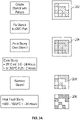
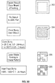
- FIGS. 3A and 3B depict different embodiments of methods by which the markings can be performed on an article.
- FIG. 3A depicts one manner of marking the article without using laser ablation while the FIG. 3B depicts another manner of marking the article using laser ablation.
- a stencil 202 is first created with a pattern on the CMC.
- the stencil 202 is fixed to the CMC part.
- a metal oxide slurry 204 is painted over the stencil.
- the slurry 204 is then cured either at room temperature or at an elevated temperature. Curing may be conducted in air at room temperature for a period of 0.5 to 24 hours, preferably 6 to 18 hours.
- the slurry may alternatively be cured at 200°C for 0.25 to 2 hours, preferably 0.5 to 1 hour.
- the stencil 202 is removed leaving behind a green marking 206.
- the slurry (which forms the green marking 206) is then heat treated for 500 to 1500°C for a period of 1 to 24 hours to leave behind a metal oxide marking 208.
- a stencil outline 302 is first created on the CMC part.
- the stencil 302 is fixed to the CMC part.
- a metal oxide slurry 304 is painted over the stencil.
- the slurry 304 is then cured either at room temperature or at an elevated temperature. Curing may be conducted in air at room temperature for a period of 0.5 to 24 hours, preferably 6 to 18 hours.
- the slurry may alternatively be cured at 180°C to 220°C for 15 minutes to 2 hours, preferably at 200°C for 15 minutes to 2 hours, preferably 30 minutes to 1 hour.
- laser ablation may be conducted on the slurry to create a green marking 306.
- the slurry (which forms the green marking 306) is then heat treated for 500 to 1500°C for a period of 1 to 24 hours to leave behind a metal oxide marking 308.
- a scanning device sends forth a beam of light (e.g., incoherent or laser) that interacts with the marking on the CMC part. A portion of the incident light is reflected back to the scanning device. A photodiode in the scanning device detects how much of the light is reflected back and this reflected light may be used to decipher the marking and identify the part.
- a beam of light e.g., incoherent or laser
- This method is advantageous in that it protects the CMC substrate from degradation by the laser beam.
- the presence of a metal oxide layer as the source of the marking prevents further oxidation of the marking.
- oxidative degradation has caused the marking to disappear over time thus making the part unidentifiable.
- the method described herein can be used to prepare a variety of components comprising matrix composites such as components in the aviation industry, marine industry and energy industry.
- exemplary components include components for gas turbine engines, such as in high pressure compressors (HPC), fans, boosters, high pressure turbines (HPT), and low pressure turbines (LPT). More specifically exemplary components include combustion liners, shrouds, nozzles, stators, vanes, and blades.
Landscapes
- Chemical & Material Sciences (AREA)
- Engineering & Computer Science (AREA)
- Ceramic Engineering (AREA)
- Materials Engineering (AREA)
- Organic Chemistry (AREA)
- Structural Engineering (AREA)
- Mechanical Engineering (AREA)
- General Engineering & Computer Science (AREA)
- Physics & Mathematics (AREA)
- Inorganic Chemistry (AREA)
- Dispersion Chemistry (AREA)
- Optics & Photonics (AREA)
- Thermal Sciences (AREA)
- Chemical Kinetics & Catalysis (AREA)
- Manufacturing & Machinery (AREA)
- Plasma & Fusion (AREA)
- Composite Materials (AREA)
- Laminated Bodies (AREA)
- Laser Beam Processing (AREA)
Abstract
Description
- Disclosed herein is a method of marking ceramic matrix composite articles. More specifically disclosed herein is a method that details the durable marking of ceramic matrix composite articles. Disclosed herein too are articles manufactured from the process.
- Manufactured parts are often marked with identifying symbols, codes or numerals so that they can be easily identified for further use. Markings facilitate ease of inventory control as parts bearing an identical marking can be stored in common locations. In addition, marking of parts prevents accidental use of parts on the wrong assembly line or on the wrong article of commerce. Accurate marking of manufactured parts therefore plays an important role in commerce by facilitating speed of storage, assembly and maintenance of articles of commerce.
- Ceramic matrix composites (CMCs) are used in a wide variety of high temperature, high stress, high performance applications such as in power generation turbines, aircraft engine turbines, and the like. These composites are particularly useful because of their high temperature capabilities and light weight. Ceramic matrix composites are manufactured by infiltrating a preform with a matrix material to form the matrix.
- Marking of CMCs poses challenges that marking of metals does not. Traditional approaches for marking metal parts can include mechanical methods like dot peening which would cause damage to a CMC because of the brittle surfaces of CMCs. Additionally, the higher temperature environments for using CMCs (such as in turbines) relative to most metal parts causes challenges when ink and pencil marking is used. Ink and pencil formulations are generally not formulated to withstand these higher temperature conditions.
- It is therefore desirable to devise methods and compositions that can be used for marking CMCs, which can withstand extended durations at high temperatures in unfavorable environments.
- In one aspect, there is provided an article comprises a substrate that comprises a ceramic matrix composite; and a metal oxide layer disposed on the substrate; where the metal oxide layer has a marking(s) etched into the metal oxide via laser ablation. The marking(s) may include alphabets, numbers, symbols, bar codes, matrix bar codes, quick response codes, or a combination thereof.
- In one embodiment, the article comprising a bond coat disposed between the substrate and the metal oxide layer.
- In another embodiment, the metal oxide layer is directly in contact with the substrate.
- In another embodiment, the ceramic matrix composite comprises fibers that comprise silicon carbide, oxide ceramics and carbon and wherein the fibers are embedded in a matrix that comprises SiC, Al2O3, BN, B4C, Si3N4, MoSi2, SiO2, SiOC, SiNC SiONC, ZrC, HfC, or a combination thereof.
- In another embodiment, the ceramic matrix composite has a different refractive index from the metal oxide layer.
- In another embodiment, the ceramic matrix composite has a different reflectivity from the metal oxide layer.
- In another embodiment, the metal oxide layer comprises a silicate, a perovskite and/or a rare earth metal oxide.
- In another embodiment, the rare earth metal oxide has a diffuse reflectivity for incident light with wavelength between 400 and 700 nm that is two times greater than the diffuse reflectivity of SiC/SiC ceramic matrix composite.
- In another embodiment, the metal oxide layer is ablated through at least 95% entire thickness.
- In another embodiment, the metal oxide layer is ablated through at least 99% entire thickness.
- In another embodiment, the metal oxide layer is ablated through its entire thickness.
- In another embodiment, the bond coat (layer) is ablated through a portion of its thickness.
- In another embodiment, a difference between the reflectivity of the CMC substrate and the metal oxide layer facilitates identification of the markings.
- In another embodiment, a difference in refractive index between the metal oxide and the CMC substrate results in reflection in incident light, which is used to identify the marking.
- There is also provided a method comprising disposing upon a ceramic matrix composite a metal oxide layer; and laser ablating the metal oxide layer to etch the metal oxide layer. The etchings produce markings that may comprise alphabets, numbers, symbols, bar codes, matrix bar codes, quick response codes, or a combination thereof.
- In an embodiment, a bond coat is disposed between the ceramic matrix composite and the metal oxide layer.
- In another embodiment, the metal oxide layer is ablated through its entire thickness.
- In another embodiment, the metal oxide layer is ablated through a portion of its entire thickness.
- There is also provided a method of identifying an article, which the Applicant expressly reserves the right to claim independently, comprising illuminating the article with an incident beam of light; where the article comprises a substrate that comprises a ceramic matrix composite; and a metal oxide layer disposed on the substrate. The metal oxide layer has a marking etched into the metal oxide via laser ablation. The marking may include alphabets, numbers, symbols, bar codes, matrix bar codes, quick response codes, or a combination thereof. Reflected light from the article is used to identify the article.
- In an embodiment, the incident beam comprises non-coherent light or a laser.
- There is also provided a method of marking a ceramic matrix composite comprising disposing upon a stencil having a pattern on a ceramic matrix composite and disposing a slurry that comprises a metal oxide on the stencil. The slurry covers the pattern. The slurry is cured. The stencil is removed. The slurry left behind after stencil removal is heat treated to produce a metal oxide layer that identifies the ceramic matrix composite. The marking may comprise alphabets, numbers, symbols, bar codes, matrix bar codes, quick response codes, or a combination thereof.
-
-
FIG. 1A depicts a metal oxide layer disposed directly on a CMC substrate prior to laser ablation; -
FIG. 1B depicts a metal oxide layer disposed directly on a bond coat that contacts a CMC substrate prior to laser ablation; -
FIG. 2A depicts a single metal oxide layer disposed directly on the CMC substrate that has been subjected to laser ablation; -
FIG. 2B depicts a single metal oxide layer disposed on the optional bond coat which is itself in contact with the CMC substrate that has been subjected to laser ablation; -
FIG. 3A depicts one method of performing the marking on a metal oxide layer; and -
FIG. 3B depicts another method of performing the marking on the metal oxide layer. - Disclosed herein are articles that have disposed on them a suitable composition that can be marked for purposes of identification. The composition includes a multilayered composite that comprises a metal oxide layer on a CMC substrate, where the metal oxide layer has a different refractive index from that of the matrix used in the CMC substrate. When regions of the metal oxide are removed via laser ablation, the difference in refractive indices between the remaining regions of metal oxide and the exposed regions of CMC surface creates a pattern with sufficient contrast between the markings and their surroundings that facilitate recognition even after extended periods of time at elevated temperatures. In addition, reflections of light from the markings also facilitate identification and recognition after extended periods of time at elevated temperatures. In an embodiment, the markings can be deciphered because of an optical contrast created due to the difference in light reflected from the metal oxide versus that reflected from the matrix material used in the CMC.
- The composition and the marking made thereon can withstand adverse conditions (e.g., high temperature, high energy electromagnetic radiation, and the like) during manufacturing and during use (e.g., high temperatures, high stresses, corrosive environments, and the like) for extended periods of time. This ability to withstand a high temperature, high energy marking process followed by survival in adverse conditions for extended periods facilitates ease of storage, maintenance and replacement of such marked parts when needed.
- Disclosed herein too is a method of marking the article using laser ablation. The method comprises disposing a layer of a metal oxide on the CMC surface such that the reflectivity of the metal oxide is different from the reflectivity of the CMC. In an embodiment, the reflectivity of the metal oxide is different from the reflectivity of the matrix used in the CMC. The metal oxide is preferably one that has a greater reflectivity from that of the matrix material used in the CMC, such as, for example, a rare earth oxide. In an embodiment, the metal oxide has a diffuse reflectivity for incident light with wavelengths between 400 and 700 nm that is at least two times greater than the diffuse reflectivity of the matrix used in the ceramic matrix composite.
- In another embodiment, the metal oxide is a rare earth metal oxide that has a diffuse reflectivity for incident light with wavelength between 400 and 700 nm that is at least two times greater than the diffuse reflectivity of the matrix used in the ceramic matrix composite. Upon ablating the rare earth metal oxide with a laser, an optical contrast is created due to the difference in light reflected from the metal oxide versus that reflected from the matrix material used in the CMC. This optical contrast facilitates identifying the marking and hence the article.
- Laser ablation methods have been used in the past to mark article surfaces. These methods have traditionally relied on changing the structure of the ceramic surface via ridges and valleys to create (light and dark) contrast. These micro-scale structures however, are prone to oxidation over time which can significantly reduce contrast. This makes the part identification difficult especially after extended periods of time when the marking has substantially disappeared. This problem can be alleviated by disposing a metal oxide on a CMC substrate, where the metal oxide has a substantially different refractive index from that of the matrix (and hence the CMC) and ablating the metal oxide down to the surface of the CMC. In one embodiment, a bond coat can be applied to the CMC surface and the metal oxide can be disposed on the bond coat. The laser ablation then may be used to ablate the metal oxide and a portion of the bond coat thereby preventing the CMC surface from damage.
-
FIGS. 1A is a depiction of anarticle 100 that comprises aCMC substrate 102 upon which is disposed ametal oxide layer 104. Themetal oxide layer 104 has a different refractive index from the matrix material used in theCMC substrate 102. In theFIG. 1A , themetal oxide layer 104 is directly disposed on theCMC substrate 102.FIG. 1B depicts thearticle 100 with three layers-aCMC substrate 102 upon which is disposed an optionalbond coat layer 106 and upon which is disposed themetal oxide layer 104. In an embodiment, the optionalbond coat layer 106 is disposed between themetal oxide layer 104 and theCMC substrate 102 and is in direct contact with both of them (on its opposing faces). - Layered structures define a wide variety of construction arrangements, including lightweight laminated composite articles. Laminated composites typically are defined by a continuous, essentially planar array of continuous fibers embedded in a matrix defining a lamina or ply, a plurality of plies forming a laminate composite. These composite articles can be arranged to meet various in-plane stiffness or strength needs by appropriate stacking of similar orthotropic plies of dissimilar orientation. Ceramic matrix composites generally comprise fibers that comprise silicon carbide, oxide ceramics and carbon. Exemplary matrix materials include SiC, Al2O3, BN, B4C, Si3N4, MoSi2, SiO2, SiOC, SiNC SiONC, ZrC, HfC, or a combination thereof. An exemplary combination of fiber and matrix (in a CMC) is silicon carbide fibers and a silicon carbide matrix.
- The refractive index for the
CMC substrate 102 is different from the refractive index of themetal oxide layer 104. The refractive index can be measured in different wavelengths of the electromagnetic spectrum. For practical reasons however it is desirable that the refractive index of theCMC substrate 102 is different from the refractive index of the metal oxide layer in the visible region of the electromagnetic spectrum and in the infrared region of the electromagnetic spectrum. The refractive index of the CMC substrate can be lower or higher than the refractive index of the metal oxide layer. - The refractive index of the CMC composite or of the CMC matrix (the matrix material used in the CMC composite) can be about 1.4 to 4.0, preferably 1.44 to 3.2, preferably 1.5 to 3.0 in the visible region of electromagnetic radiation.
- The
metal oxide layer 104 is disposed directly on the CMC substrate 102 (seeFIG. 1A ) or on thebond coat layer 106 that contacts the CMC substrate (seeFIG. 1B ). It is desirable for the metal oxide to form covalent or ionic bonds with oxides that form on the CMC substrate or on the bond coat substrate. These bonds prevent delamination or cracking of the metal oxide layer when subjected to elevated temperatures because of the inherent different coefficients of thermal expansion for the CMC substrate, the bond coat and the metal oxide layer. It is further desirable to use a metal oxide that has a coefficient of thermal expansion that is substantially close to that of the CMC material (the CMC composite as a whole or the matrix material) and/or the bond coat so that cracking and/or delamination is avoided. - The metal oxide can preferably undergo laser ablation without undergoing degradation or cracking. It is preferable for the metal oxide to not generate compounds that can degrade the CMC during the laser ablation process. For this reason, it is desirable to use metal oxides that are free from halogens, nitrates, sulfates, phosphates, or a combination thereof. The
metal oxide layer 104 comprises a metal oxide that has a different refractive index from that of the CMC matrix. - Examples of metal oxides that may be used for the metal oxide layer include silicates, aluminates, titanates, zirconates, perovskites, rare earth metal oxides, and so forth that can bond with silicates, aluminates, and the like formed on the surface of the CMC composite.
- Exemplary metal oxides include silicates, zirconates, titanates, aluminates, stannates, niobates, tantalates and rare earth oxides. Exemplary inorganic oxides include silica, aluminum oxide, silicon dioxide, calcium oxide, cerium oxide, copper oxide, titanium oxide, zinc oxide, zirconium oxide, tantalum oxide, niobium oxide, yttrium oxide, magnesium oxide, Mg2SiO4, MgO, CaTiO3, MgZrSrTiO6, MgTiO3, MgAl2O4, WO3, SnTiO4, ZrTiO4, CaSiO3, CaSnO3, CaWO4, CaZrO3, MgTa2O6, MgZrO3, MnO2, PbO, Bi2O3 and La2O3, CaZrO3, BaZrO3, SrZrO3, BaSnO3, CaSnO3, MgSnO3, Bi2O3/2SnO2, Nd2O3, Pr7O11, Yb2O3, HO2O3, La2O3, MgNb2O6, SrNb2O6, BaNb2O6, MgTa2O6, BaTa2O6, Ta2O3, or the like, or a combination thereof. Exemplary metal oxides include Mg2SiO4, MgO, CaTiO3, MgZrSrTiO6, MgTiO3, MgAl2O4, MgTa2O6, MgZrO3, or the like, or a combination thereof.
- Silicates are preferred. Silicates that may be used in the metal oxide layer are preferably from Group 2A of the Periodic Table, i.e., berrylium (Be), magnesium (Mg), calcium (Ca), strontium (Sr), barium (Ba) and radium (Ra). Preferred metal silicates include Mg2SiO4, CaSiO3, BaSiO3 and SrSiO3. In addition to Group 2A metals, the present metal silicates may include metals from Group 1A, i.e., lithium (Li), sodium (Na), potassium (K), rubidium (Rb), cesium (Cs) and francium (Fr). For example, metal silicates may include sodium silicates such as Na2SiO3 and NaSiO3-5H2O, lithium silicates such as LiAlSiO4, Li2SiO3 and Li4SiO4. Additional metal silicates may include Al2Si2O7, ZrSiO4, KAlSi3O8, NaAlSi3O3, CaAl2Si2O8, CaMgSi2O6, BaTiSi3O9, Zn2SiO4 or a combination thereof.
- The rare-earth elements, also called the rare-earth metals or the lanthanides (yttrium and scandium are included as rare-earths) are a set of 17 nearly indistinguishable lustrous silvery-white soft heavy metals. Scandium and yttrium are considered rare-earth elements because they tend to occur in the same ore deposits as the lanthanides and exhibit similar chemical properties but have different electronic and magnetic properties. Rare earth oxides include oxides of lanthanum, cerium, praseodymium, neodymium, promethium, samarium, europium, gadolinium, terbium, dysprosium, holmium, erbium, thulium, ytterbium, lutetium, scandium, yttrium, or a combination thereof.
- The rare earth oxide has a refractive index that is different from that of the CMC. The rare earth oxides generally have refractive index values of 1.5 to 2.7, preferably 1.7 to 2.3 and more preferably 1.8 to 2.2. For example, La2O3 has a refractive index ranging from 1.85 to 1.95 with increasing thickness, Pr6O11 from 1.92 to 2.05, also with increasing thickness, and Nd2O3 with a value of refractive of n = 2.05. Rare earth metal oxides are preferred for use in the
metal oxide layer 104. - The
metal oxide layer 104 is disposed on theCMC substrate 102 via a sol gel reaction, a slurry, or alternatively, themetal oxide layer 104 is preformed and disposed directly on the CMC substrate. - The
metal oxide layer 104 may have a thickness of 0.025 to 0.8 millimeters, preferably 0.05 to 0.5 millimeters, preferably 0.1 to 0.4 millimeters. - The
bond coat 106 is an optional layer and may be used on those occasions when it is desirable to protect the CMC composite 102 from the effects of laser ablation. Thebond coat 106 is used to permit the laser ablation to remove a portion of themetal oxide layer 104 and a portion of thebond coat 106 without penetrating or disturbing theCMC substrate 102. - The
bond coating 106 prevents theCMC substrate 102 from oxidation in a range of temperatures from room temperature to up to at least about 3000° F (1650° C) and greater. The bond coating is an exemplary protective coating that take advantages of glass materials having low melting point temperatures in combination with oxygen scavenging additives to achieve high mechanical and oxidation resistant properties suitable for the refractory based substrate. - A process for applying an oxidation resistant coating may comprise mixing at least about 10% by volume to up to about 99% by volume of at least one silica based material and at least about 1% by volume to up to about 90% by volume of at least one oxygen scavenger in a liquid medium to form a slurry. Suitable liquid media include water, alcohols, binders, terpineol, or a combination thereof.
- The binders may be organic-based liquid media such as acrylic polymers, or alternatively, inorganic-based such as colloidal silica. Suitable mixing processes may include, but are not limited to, mechanical mixing techniques, manual mixing techniques, ultrasonics, cavitation, agitation, combinations comprising these techniques, and the like. For example, representative mechanical mixing techniques may include grinding, ball mixing, high energy milling (e.g., Spex), shear mixing, stirring, centrifugal mixing, combinations comprising at least one of the foregoing, and the like.
- Suitable silica based materials may comprise silica, modified silica, and the like. Modified silica may comprise silica modified by other compounds or elements, for example, silicates such as sodium silicate, borosilicates, hafnium silicates, zirconium silicates, and mixtures thereof. These various silica based materials exhibit a viscosity of about 1×10² poise to about 1×10⁷ poise in a temperature range of about 1,292° F (700° C) to about 3,272° F (1,800° C), possess a particle size range of about 150 mesh to about 325 mesh, and form a viscous glass phase material when heat treated that is suitable as a carrier for at least one oxygen scavenger. This viscosity range permits easier inclusion and dispersion of the oxygen scavengers throughout the silica based materials during the coating and heat treatment steps.
- The oxidation resistant coating of the present invention provides oxidation resistance primarily by active reaction with oxygen rather than only providing a passive barrier to oxygen flow to an article's surface. As the coating(s) are exposed to oxidative operating conditions, the coating(s) erodes and exposes the oxygen scavenger additives. The oxygen scavengers oxidize to form non-gaseous oxidation products such as SiO2, Al2O3, B2O3, etc., which then add to and rebuild the coating. The glassy phase flows at elevated temperature to seal cracks and accommodate mismatches of the coefficient of thermal expansion of the various layers. As a result, the coating in turn resists spallation and cracking and instead relieves the stress caused by the formation of the non-gaseous oxidation products.
- The oxygen scavenger may be an element or compound or multiphase component that reacts with oxygen to form a relatively stable, non volatile oxygen-containing compound or phase. Suitable oxygen scavengers may comprise silicides and/or borides of aluminum, molybdenum, tantalum, chromium, titanium, hafnium, zirconium, yttrium, mixtures thereof, and the like. In addition, other refractory metals, and other metals that form refractory oxides, silicates, borides, and mixtures thereof, known to one of ordinary skill in the art may also be utilized as suitable oxygen scavengers. The volume percent of the oxygen scavenger within the layers of coating may preferably be in the range of about 1% to about 90% by volume of the layers of coating, and more preferably in the range of about 5% to about 75% by volume of the layers of coating.
- If desirable, a viscosity modifier may be added to the slurry in an amount sufficient to rheologically control the viscosity of the targeted glass phase(s). Suitable viscosity modifiers may include, but are not limited to refractory materials, metal oxides, mixed metal silicates, mixtures thereof, and the like. Optionally, a viscosity modifier additive may be added to the slurry to impart steam resistance to the article. In the alternative, the silica based material may also include, as part of its composition, the viscosity modifier additive. Suitable viscosity modifier additives may include mullite, alkaline earth aluminosilicates including barium strontium aluminosilicate (BSAS) and strontium aluminosilicate (SAS), yttrium silicates, rare earth silicates, hafnium or zirconium silicate, oxides of hafnium, zirconium, titanium, silicon, yttrium, rare earth metals, tantalum, niobium, aluminum and mixtures thereof, and the like. In addition, these viscosity modifier additives may also be used to impart additional steam resistance.
- After disposing the slurry containing the
bond coat 106 precursors to theCMC substrate 102, it is subjected to heat and pressure to evaporate the liquid components such as solvents and so on. Pressure may be used to facilitate bonding of thebond coat 106 to theCMC substrate 102. Following the formation of theoptional bond coat 106, themetal oxide layer 104 is disposed on the bond coat 106 (if present) or directly on theCMC substrate 102. Themetal oxide layer 104 is then heat treated to remove solvents (if applied in the form of sol gel solution) and/or to bond themetal oxide layer 104 to thebond coat 106 or to theCMC substrate 102. TheCMC substrate 102 with theoptional bond coat 106 and themetal oxide layer 104 disposed thereon is referred to herein as a multilayer composite. The multilayer composite is then subjected to laser ablation to create the marking that identifies the part. - The
metal oxide layer 104 is then subjected to laser ablation to etch away a portion of the metal oxide layer to create the marking that identifies the part. In an embodiment, themetal oxide layer 104 is etched to the interface with thebond coat 106 or to the interface with theCMC substrate 102 when thebond coat 106 is not used. In another embodiment, themetal oxide layer 104 is etched below the interface of themetal oxide layer 104 with thebond coat 106 and into the portion of thebond coat 106. A portion of the bond coat above the surface of theCMC substrate 102 is left untouched, thus protecting theCMC substrate 102 from any adverse effects of the ablation. - These concepts are depicted in the
FIGS. 2A and 2B . TheFIG. 2A depicts a singlemetal oxide layer 104 disposed on theCMC substrate 102. In one embodiment, only a portion of the metal oxide layer 104 (as viewed from the top) is ablated and removed in the process of marking the multilayer composite. In another embodiment, the entire thickness of the metal oxide is ablated and a portion of the CMC may also be ablated in order to form the marking. Both of these are detailed below. Letters, numbers, symbols, bar codes, matrix bar codes (e.g., QR codes also known as quick response codes) or a combination thereof may be ablated into the metal oxide layer to serve as markings for identifying the component. - In one embodiment (not shown), the markings may be developed by ablating the metal oxide (and the bond coat-see
FIG. 2B ) down into the CMC. A portion of the CMC may be removed during the laser ablation, leaving the portions of the metal oxide (that forms the boundaries of the marking) on the surface of the CMC. Incident light reflected from the ablated surface (from the markings) may be collected and analyzed in order to identify the part. - In another embodiment, in those regions where the metal oxide is contacted by the laser beam almost the entire height (i.e., the thickness) of the material is removed. In this embodiment, during the laser ablation of the
metal oxide layer 104 it is desirable to leave the CMC substrate untouched by the laser beam. In other words, the thickness of the metal oxide layer is reduced almost to zero in those regions that are ablated while the surrounding metal oxide is left untouched. A very thin portion of the metal oxide layer 104 (less than 5% of the original thickness, preferably less than 1% of the original thickness) is still in contact with theCMC substrate 102 after the laser ablation. In an exemplary embodiment, the residual coating should be less than 1 micrometer. At 1 micrometer thickness or less, some incident light will transmit through the coating and reflect off of the underlying CMC, giving a different visual appearance, which is used to identify the marking. - In another embodiment, in some cases, a small amount (less than 50% of the coating thickness) is removed from the underlying CMC. The difference in refractive index between the
metal oxide layer 104 and theCMC substrate 102 results in different amounts of light being reflected or scattered thus making the markings visible and consequently the component identifiable. -
FIG. 2B depicts a singlemetal oxide layer 104 disposed on theoptional bond coat 106 which is itself in contact with theCMC substrate 102. In this case, the laser ablation is conducted through the thickness of themetal oxide layer 104 and into a portion of the thickness of thebond coat 106. The portion of thebond coat 106 that is not removed protects theCMC substrate 102 from degradation that may be caused by the laser beam. The difference in refractive index between themetal oxide layer 104 and thebond coat 106 or theCMC substrate 102 results in different amounts of light being reflected or scattered thus making the markings visible and consequently the component identifiable. -
FIGS. 3A and3B depict different embodiments of methods by which the markings can be performed on an article.FIG. 3A depicts one manner of marking the article without using laser ablation while theFIG. 3B depicts another manner of marking the article using laser ablation. - In
FIG. 3A , astencil 202 is first created with a pattern on the CMC. Thestencil 202 is fixed to the CMC part. Ametal oxide slurry 204 is painted over the stencil. Theslurry 204 is then cured either at room temperature or at an elevated temperature. Curing may be conducted in air at room temperature for a period of 0.5 to 24 hours, preferably 6 to 18 hours. The slurry may alternatively be cured at 200°C for 0.25 to 2 hours, preferably 0.5 to 1 hour. Following curing, thestencil 202 is removed leaving behind agreen marking 206. The slurry (which forms the green marking 206) is then heat treated for 500 to 1500°C for a period of 1 to 24 hours to leave behind a metal oxide marking 208. - In
FIG. 3B , astencil outline 302 is first created on the CMC part. Thestencil 302 is fixed to the CMC part. Ametal oxide slurry 304 is painted over the stencil. Theslurry 304 is then cured either at room temperature or at an elevated temperature. Curing may be conducted in air at room temperature for a period of 0.5 to 24 hours, preferably 6 to 18 hours. The slurry may alternatively be cured at 180°C to 220°C for 15 minutes to 2 hours, preferably at 200°C for 15 minutes to 2 hours, preferably 30 minutes to 1 hour. Following curing, laser ablation may be conducted on the slurry to create agreen marking 306. The slurry (which forms the green marking 306) is then heat treated for 500 to 1500°C for a period of 1 to 24 hours to leave behind a metal oxide marking 308. - In an embodiment, in one method of reading the marking, a scanning device sends forth a beam of light (e.g., incoherent or laser) that interacts with the marking on the CMC part. A portion of the incident light is reflected back to the scanning device. A photodiode in the scanning device detects how much of the light is reflected back and this reflected light may be used to decipher the marking and identify the part.
- This method is advantageous in that it protects the CMC substrate from degradation by the laser beam. The presence of a metal oxide layer as the source of the marking prevents further oxidation of the marking. In the past, oxidative degradation has caused the marking to disappear over time thus making the part unidentifiable.
- The method described herein can be used to prepare a variety of components comprising matrix composites such as components in the aviation industry, marine industry and energy industry. Exemplary components include components for gas turbine engines, such as in high pressure compressors (HPC), fans, boosters, high pressure turbines (HPT), and low pressure turbines (LPT). More specifically exemplary components include combustion liners, shrouds, nozzles, stators, vanes, and blades.
- While the invention has been described with reference to some embodiments, it will be understood by those skilled in the art that various changes may be made and equivalents may be substituted for elements thereof without departing from the scope of the invention. In addition, many modifications may be made to adapt a particular situation or material to the teachings of the invention without departing from essential scope thereof. Therefore, it is intended that the invention not be limited to the particular embodiments disclosed as the best mode contemplated for carrying out this invention, but that the invention will include all embodiments falling within the scope of the appended claims.
Claims (15)
- An article (100) comprising:a substrate (102) that comprises a ceramic matrix composite; anda metal oxide layer (104) disposed on the substrate (102); where the metal oxide layer (104) has a marking (308) etched into the metal oxide (104) via laser ablation.
- The article (100) of claim 1, wherein the marking (308) includes alphabets, numbers, symbols, bar codes, matrix bar codes, quick response codes, or a combination thereof.
- The article (100) of claim 1 or 2, further comprising a bond coat (106) disposed between the substrate (102) and the metal oxide layer (104), wherein, optionally, the bond coat (106) is ablated through a portion of its thickness.
- The article (100) of claim 1 or 2, wherein the metal oxide layer (104) is directly in contact with the substrate (102).
- The article (100) of any preceding claim, wherein the ceramic matrix composite comprises fibers that comprise silicon carbide, oxide ceramics and carbon and wherein the fibers are embedded in a matrix that comprises SiC, Al2O3, BN, B4C, Si3N4, MoSi2, SiO2, SiOC, SiNC SiONC, ZrC, HfC, or a combination thereof.
- The article (100) of any preceding claim, wherein the ceramic matrix composite comprises a matrix that has a different reflectivity from the metal oxide layer (104), wherein, optionally, the metal oxide layer (104) has a greater reflectivity from that of the matrix material used in the ceramic matrix composite.
- The article (100) of any preceding claim, wherein the metal oxide layer (104) is ablated through at least 95% entire thickness, optionally through at least 99% entire thickness, further optionally through its entire thickness.
- The article (100) of any preceding claim, wherein the metal oxide is a rare earth metal oxide that has a diffuse reflectivity for incident visible light that is two times greater than the diffuse reflectivity of the ceramic matrix composite, wherein the ceramic matrix composite optionally comprises silicon carbide.
- A method of marking a ceramic matrix composite (102) comprising:disposing upon a ceramic matrix composite (102) a metal oxide layer (104); andlaser ablating the metal oxide layer (104) to etch the metal oxide layer (104); where the etching produces markings (308).
- The method of claim 9, wherein the markings (308) comprise alphabets, numbers, symbols, bar codes, matrix bar codes, quick response codes, or a combination thereof.
- The method of claim 9 or 10, further comprising disposing a bond coat (106) between the ceramic matrix composite (102) and the metal oxide layer (104).
- The method of any of claims 9 to 11, wherein the metal oxide layer (104) is ablated through its entire thickness, or wherein the metal oxide layer (104) is ablated through a portion of its entire thickness.
- The method of any of claims 9 to 12, wherein the metal oxide layer (104) is disposed on the ceramic matrix composite (102) in the form of a slurry (304), wherein, optionally:the slurry (304) is bounded by a stencil (302);the slurry (304) is cured by heating it prior to laser ablation; and/orthe metal oxide (104) is heated to 500 to 1500°C for a period of 1 to 24 hours after laser ablation.
- A method of marking a ceramic matrix composite (102) comprising:disposing upon a stencil (202) having a pattern on a ceramic matrix composite (102);disposing a slurry (204) that comprises a metal oxide on the stencil (202); where the slurry (204) covers the pattern;curing the slurry (204), wherein, optionally, the curing is conducted in air at room temperature for 30 minutes to 24 hours or at a temperature of about 180°C to 220°C for 15 minutes to 2 hours.;removing the stencil (202); andheat treating the slurry (204) to produce a metal oxide layer (104) with a marking (208) that identifies the ceramic matrix composite (102), wherein the marking (208) optionally comprises alphabets, numbers, symbols, bar codes, matrix bar codes, quick response codes, or a combination thereof, wherein, optionally the slurry (204) is heat treated at a temperature of 500°C to 1500°C for 1 to 24 hours.
- A method of identifying an article (100) of any of claims 1 to 8 comprising:illuminating the article (100) with an incident beam of light, wherein the incident beam of light optionally comprises non-coherent light or a laser;receiving a reflected beam of light from the article (100); andidentifying the article (100) from the reflected beam of light.
Priority Applications (1)
| Application Number | Priority Date | Filing Date | Title |
|---|---|---|---|
| EP25219566.4A EP4678876A3 (en) | 2021-07-23 | 2022-07-22 | Method of marking ceramic matrix composites and articles manufactured therefrom |
Applications Claiming Priority (1)
| Application Number | Priority Date | Filing Date | Title |
|---|---|---|---|
| US202163225052P | 2021-07-23 | 2021-07-23 |
Related Child Applications (1)
| Application Number | Title | Priority Date | Filing Date |
|---|---|---|---|
| EP25219566.4A Division EP4678876A3 (en) | 2021-07-23 | 2022-07-22 | Method of marking ceramic matrix composites and articles manufactured therefrom |
Publications (3)
| Publication Number | Publication Date |
|---|---|
| EP4122904A2 true EP4122904A2 (en) | 2023-01-25 |
| EP4122904A3 EP4122904A3 (en) | 2023-05-24 |
| EP4122904B1 EP4122904B1 (en) | 2025-12-24 |
Family
ID=83191882
Family Applications (2)
| Application Number | Title | Priority Date | Filing Date |
|---|---|---|---|
| EP25219566.4A Pending EP4678876A3 (en) | 2021-07-23 | 2022-07-22 | Method of marking ceramic matrix composites and articles manufactured therefrom |
| EP22186474.7A Active EP4122904B1 (en) | 2021-07-23 | 2022-07-22 | Method of marking ceramic matrix composites and articles manufactured therefrom |
Family Applications Before (1)
| Application Number | Title | Priority Date | Filing Date |
|---|---|---|---|
| EP25219566.4A Pending EP4678876A3 (en) | 2021-07-23 | 2022-07-22 | Method of marking ceramic matrix composites and articles manufactured therefrom |
Country Status (2)
| Country | Link |
|---|---|
| US (1) | US20230021947A1 (en) |
| EP (2) | EP4678876A3 (en) |
Cited By (1)
| Publication number | Priority date | Publication date | Assignee | Title |
|---|---|---|---|---|
| WO2025052060A1 (en) * | 2023-09-06 | 2025-03-13 | Safran Ceramics | Marking coating for an oxide/oxide substrate |
Families Citing this family (1)
| Publication number | Priority date | Publication date | Assignee | Title |
|---|---|---|---|---|
| CN120573951B (en) * | 2025-08-01 | 2025-10-28 | 福建德化佳得宝工艺品有限公司 | A crystallization kiln-changed glaze, a ceramic material using the same, and a preparation method thereof |
Family Cites Families (7)
| Publication number | Priority date | Publication date | Assignee | Title |
|---|---|---|---|---|
| US4869943A (en) * | 1985-01-17 | 1989-09-26 | Norton Company | Fiber-reinforced silicon nitride ceramics |
| US6165594A (en) * | 1998-01-15 | 2000-12-26 | 3M Innovative Properties Company | Multilayer, temperature resistant, composite label |
| US20050082725A1 (en) * | 2003-10-17 | 2005-04-21 | Lieb David P. | Production of improved zirconia products |
| DE102006019118B4 (en) * | 2006-04-25 | 2011-08-18 | Epcos Ag, 81669 | Optical marking component and method of manufacture |
| US9005717B2 (en) * | 2009-07-31 | 2015-04-14 | General Electric Company | Methods for making environmental barrier coatings using sintering aids |
| US10399911B2 (en) * | 2015-01-27 | 2019-09-03 | Rolls-Royce Corporation | Forming a surface layer of a ceramic matrix composite article |
| EP3219696A1 (en) * | 2016-03-14 | 2017-09-20 | Siemens Aktiengesellschaft | Cmc with outer ceramic layer |
-
2022
- 2022-07-22 EP EP25219566.4A patent/EP4678876A3/en active Pending
- 2022-07-22 EP EP22186474.7A patent/EP4122904B1/en active Active
- 2022-07-22 US US17/871,008 patent/US20230021947A1/en active Pending
Cited By (1)
| Publication number | Priority date | Publication date | Assignee | Title |
|---|---|---|---|---|
| WO2025052060A1 (en) * | 2023-09-06 | 2025-03-13 | Safran Ceramics | Marking coating for an oxide/oxide substrate |
Also Published As
| Publication number | Publication date |
|---|---|
| EP4122904B1 (en) | 2025-12-24 |
| US20230021947A1 (en) | 2023-01-26 |
| EP4678876A3 (en) | 2026-04-08 |
| EP4678876A2 (en) | 2026-01-14 |
| EP4122904A3 (en) | 2023-05-24 |
Similar Documents
| Publication | Publication Date | Title |
|---|---|---|
| EP4122904B1 (en) | Method of marking ceramic matrix composites and articles manufactured therefrom | |
| US11370717B2 (en) | Protective coating systems for gas turbine engine applications | |
| CN105189932B (en) | Sag resistant ceramic matrix composite and environmental barrier coat | |
| JP6533211B2 (en) | Dent resistant ceramic matrix composite and environmental coating | |
| RU2420612C2 (en) | Coating (versions), part of gas-turbine engine and protection method of part against damages related to sand effect | |
| JP6616282B2 (en) | Thinning resistant ceramic matrix composite and environmental coating | |
| JP7038504B2 (en) | How to make contouring bond coats for environmental barrier coatings and contouring bond coats for environmental barrier coatings | |
| KR20070090065A (en) | Adhesive protective coating, method of providing invisible line of adhesive protective coating and coated article | |
| CN105689230A (en) | Articles for high temperature service and method for making | |
| EP3597871B1 (en) | Environmental barrier multi-phase abradable coating | |
| JP2019518137A (en) | Thermal barrier system with bond coat barrier | |
| CN101024324A (en) | Environment barrier coating for a component and method for fabricating the same | |
| US20220341335A1 (en) | Barrier layer and surface preparation thereof | |
| US20220081750A1 (en) | Silicon oxycarbide-based environmental barrier coating | |
| US20200087220A1 (en) | Method of pressure sintering an environmental barrier coating on a surface of a ceramic substrate | |
| US20140272167A1 (en) | High temperature stable amorphous silica-rich aluminosilicates | |
| CN117986043A (en) | Repair of defects extending into the underlying layer of the environmental barrier coating | |
| CN114575933A (en) | Method for repairing silicon-based product by using paste-based patch | |
| US11236023B2 (en) | Method of forming a protective coating on a surface of a ceramic substrate | |
| US20090098394A1 (en) | Strain tolerant corrosion protecting coating and tape method of application | |
| US20220098122A1 (en) | Method of pressure sintering an environmental barrier coating on a surface of a ceramic substrate | |
| CN115873498A (en) | Corrosion Resistant Coating | |
| US12228051B1 (en) | Components having coating systems comprising mud cracks and methods for forming the coating systems | |
| EP3153486B1 (en) | Method for coating removal | |
| US12606498B2 (en) | Methods to remove an EBC from a substrate and to repair a coated component |
Legal Events
| Date | Code | Title | Description |
|---|---|---|---|
| PUAI | Public reference made under article 153(3) epc to a published international application that has entered the european phase |
Free format text: ORIGINAL CODE: 0009012 |
|
| STAA | Information on the status of an ep patent application or granted ep patent |
Free format text: STATUS: THE APPLICATION HAS BEEN PUBLISHED |
|
| AK | Designated contracting states |
Kind code of ref document: A2 Designated state(s): AL AT BE BG CH CY CZ DE DK EE ES FI FR GB GR HR HU IE IS IT LI LT LU LV MC MK MT NL NO PL PT RO RS SE SI SK SM TR |
|
| PUAL | Search report despatched |
Free format text: ORIGINAL CODE: 0009013 |
|
| AK | Designated contracting states |
Kind code of ref document: A3 Designated state(s): AL AT BE BG CH CY CZ DE DK EE ES FI FR GB GR HR HU IE IS IT LI LT LU LV MC MK MT NL NO PL PT RO RS SE SI SK SM TR |
|
| RIC1 | Information provided on ipc code assigned before grant |
Ipc: F01D 5/28 20060101ALI20230418BHEP Ipc: C04B 41/89 20060101ALI20230418BHEP Ipc: C04B 41/85 20060101AFI20230418BHEP |
|
| RAP3 | Party data changed (applicant data changed or rights of an application transferred) |
Owner name: RTX CORPORATION |
|
| STAA | Information on the status of an ep patent application or granted ep patent |
Free format text: STATUS: REQUEST FOR EXAMINATION WAS MADE |
|
| 17P | Request for examination filed |
Effective date: 20231122 |
|
| RBV | Designated contracting states (corrected) |
Designated state(s): AL AT BE BG CH CY CZ DE DK EE ES FI FR GB GR HR HU IE IS IT LI LT LU LV MC MK MT NL NO PL PT RO RS SE SI SK SM TR |
|
| GRAP | Despatch of communication of intention to grant a patent |
Free format text: ORIGINAL CODE: EPIDOSNIGR1 |
|
| STAA | Information on the status of an ep patent application or granted ep patent |
Free format text: STATUS: GRANT OF PATENT IS INTENDED |
|
| INTG | Intention to grant announced |
Effective date: 20250717 |
|
| GRAS | Grant fee paid |
Free format text: ORIGINAL CODE: EPIDOSNIGR3 |
|
| GRAA | (expected) grant |
Free format text: ORIGINAL CODE: 0009210 |
|
| STAA | Information on the status of an ep patent application or granted ep patent |
Free format text: STATUS: THE PATENT HAS BEEN GRANTED |
|
| AK | Designated contracting states |
Kind code of ref document: B1 Designated state(s): AL AT BE BG CH CY CZ DE DK EE ES FI FR GB GR HR HU IE IS IT LI LT LU LV MC MK MT NL NO PL PT RO RS SE SI SK SM TR |
|
| REG | Reference to a national code |
Ref country code: CH Ref legal event code: F10 Free format text: ST27 STATUS EVENT CODE: U-0-0-F10-F00 (AS PROVIDED BY THE NATIONAL OFFICE) Effective date: 20251224 Ref country code: GB Ref legal event code: FG4D |
|
| REG | Reference to a national code |
Ref country code: DE Ref legal event code: R096 Ref document number: 602022027305 Country of ref document: DE |
|
| REG | Reference to a national code |
Ref country code: LT Ref legal event code: MG9D |
|
| PG25 | Lapsed in a contracting state [announced via postgrant information from national office to epo] |
Ref country code: NO Free format text: LAPSE BECAUSE OF FAILURE TO SUBMIT A TRANSLATION OF THE DESCRIPTION OR TO PAY THE FEE WITHIN THE PRESCRIBED TIME-LIMIT Effective date: 20260324 |
|
| PG25 | Lapsed in a contracting state [announced via postgrant information from national office to epo] |
Ref country code: FI Free format text: LAPSE BECAUSE OF FAILURE TO SUBMIT A TRANSLATION OF THE DESCRIPTION OR TO PAY THE FEE WITHIN THE PRESCRIBED TIME-LIMIT Effective date: 20251224 Ref country code: HR Free format text: LAPSE BECAUSE OF FAILURE TO SUBMIT A TRANSLATION OF THE DESCRIPTION OR TO PAY THE FEE WITHIN THE PRESCRIBED TIME-LIMIT Effective date: 20251224 |
|
| PG25 | Lapsed in a contracting state [announced via postgrant information from national office to epo] |
Ref country code: RS Free format text: LAPSE BECAUSE OF FAILURE TO SUBMIT A TRANSLATION OF THE DESCRIPTION OR TO PAY THE FEE WITHIN THE PRESCRIBED TIME-LIMIT Effective date: 20260324 |
|
| PG25 | Lapsed in a contracting state [announced via postgrant information from national office to epo] |
Ref country code: LV Free format text: LAPSE BECAUSE OF FAILURE TO SUBMIT A TRANSLATION OF THE DESCRIPTION OR TO PAY THE FEE WITHIN THE PRESCRIBED TIME-LIMIT Effective date: 20251224 |