EP4122852A1 - Conveyance path switching mechanism, and paper sheet handling device - Google Patents
Conveyance path switching mechanism, and paper sheet handling device Download PDFInfo
- Publication number
- EP4122852A1 EP4122852A1 EP20925695.7A EP20925695A EP4122852A1 EP 4122852 A1 EP4122852 A1 EP 4122852A1 EP 20925695 A EP20925695 A EP 20925695A EP 4122852 A1 EP4122852 A1 EP 4122852A1
- Authority
- EP
- European Patent Office
- Prior art keywords
- gear
- conveyance
- gate
- shaft
- conveyance path
- Prior art date
- Legal status (The legal status is an assumption and is not a legal conclusion. Google has not performed a legal analysis and makes no representation as to the accuracy of the status listed.)
- Granted
Links
Images




Classifications
-
- B—PERFORMING OPERATIONS; TRANSPORTING
- B65—CONVEYING; PACKING; STORING; HANDLING THIN OR FILAMENTARY MATERIAL
- B65H—HANDLING THIN OR FILAMENTARY MATERIAL, e.g. SHEETS, WEBS, CABLES
- B65H29/00—Delivering or advancing articles from machines; Advancing articles to or into piles
- B65H29/58—Article switches or diverters
- B65H29/60—Article switches or diverters diverting the stream into alternative paths
-
- B—PERFORMING OPERATIONS; TRANSPORTING
- B65—CONVEYING; PACKING; STORING; HANDLING THIN OR FILAMENTARY MATERIAL
- B65H—HANDLING THIN OR FILAMENTARY MATERIAL, e.g. SHEETS, WEBS, CABLES
- B65H29/00—Delivering or advancing articles from machines; Advancing articles to or into piles
- B65H29/58—Article switches or diverters
-
- B—PERFORMING OPERATIONS; TRANSPORTING
- B65—CONVEYING; PACKING; STORING; HANDLING THIN OR FILAMENTARY MATERIAL
- B65H—HANDLING THIN OR FILAMENTARY MATERIAL, e.g. SHEETS, WEBS, CABLES
- B65H5/00—Feeding articles separated from piles; Feeding articles to machines
- B65H5/26—Duplicate, alternate, selective, or coacting feeds
-
- B—PERFORMING OPERATIONS; TRANSPORTING
- B65—CONVEYING; PACKING; STORING; HANDLING THIN OR FILAMENTARY MATERIAL
- B65H—HANDLING THIN OR FILAMENTARY MATERIAL, e.g. SHEETS, WEBS, CABLES
- B65H2301/00—Handling processes for sheets or webs
- B65H2301/30—Orientation, displacement, position of the handled material
- B65H2301/31—Features of transport path
- B65H2301/312—Features of transport path for transport path involving at least two planes of transport forming an angle between each other
- B65H2301/3125—T-shaped
-
- B—PERFORMING OPERATIONS; TRANSPORTING
- B65—CONVEYING; PACKING; STORING; HANDLING THIN OR FILAMENTARY MATERIAL
- B65H—HANDLING THIN OR FILAMENTARY MATERIAL, e.g. SHEETS, WEBS, CABLES
- B65H2403/00—Power transmission; Driving means
- B65H2403/40—Toothed gearings
- B65H2403/41—Rack-and-pinion, cogwheel in cog railway
-
- B—PERFORMING OPERATIONS; TRANSPORTING
- B65—CONVEYING; PACKING; STORING; HANDLING THIN OR FILAMENTARY MATERIAL
- B65H—HANDLING THIN OR FILAMENTARY MATERIAL, e.g. SHEETS, WEBS, CABLES
- B65H2403/00—Power transmission; Driving means
- B65H2403/40—Toothed gearings
- B65H2403/48—Other
- B65H2403/481—Planetary
-
- B—PERFORMING OPERATIONS; TRANSPORTING
- B65—CONVEYING; PACKING; STORING; HANDLING THIN OR FILAMENTARY MATERIAL
- B65H—HANDLING THIN OR FILAMENTARY MATERIAL, e.g. SHEETS, WEBS, CABLES
- B65H2403/00—Power transmission; Driving means
- B65H2403/90—Machine drive
- B65H2403/94—Other features of machine drive
- B65H2403/942—Bidirectional powered handling device
-
- B—PERFORMING OPERATIONS; TRANSPORTING
- B65—CONVEYING; PACKING; STORING; HANDLING THIN OR FILAMENTARY MATERIAL
- B65H—HANDLING THIN OR FILAMENTARY MATERIAL, e.g. SHEETS, WEBS, CABLES
- B65H2404/00—Parts for transporting or guiding the handled material
- B65H2404/60—Other elements in face contact with handled material
- B65H2404/63—Oscillating, pivoting around an axis parallel to face of material, e.g. diverting means
- B65H2404/632—Wedge member
-
- B—PERFORMING OPERATIONS; TRANSPORTING
- B65—CONVEYING; PACKING; STORING; HANDLING THIN OR FILAMENTARY MATERIAL
- B65H—HANDLING THIN OR FILAMENTARY MATERIAL, e.g. SHEETS, WEBS, CABLES
- B65H2513/00—Dynamic entities; Timing aspects
- B65H2513/40—Movement
- B65H2513/42—Route, path
-
- B—PERFORMING OPERATIONS; TRANSPORTING
- B65—CONVEYING; PACKING; STORING; HANDLING THIN OR FILAMENTARY MATERIAL
- B65H—HANDLING THIN OR FILAMENTARY MATERIAL, e.g. SHEETS, WEBS, CABLES
- B65H2701/00—Handled material; Storage means
- B65H2701/10—Handled articles or webs
- B65H2701/19—Specific article or web
- B65H2701/1912—Banknotes, bills and cheques or the like
Definitions
- the present invention relates to a conveyance route switching mechanism and a paper sheet handling apparatus.
- Patent Literature 1 JP 2016-147751 A
- conveyance routes of paper sheets are complicatedly switched, for example, in such a way that in a position where three conveyance paths cross each other, a conveyance route is switched between a conveyance route that connects one conveyance path and two remaining conveyance paths and a conveyance route that connects another conveyance path and two remaining conveyance paths, and therefore the number of conveyance paths can be reduced in the paper sheet handling apparatus. This enables space saving.
- one driving means is used in the conveyance switching apparatus described above.
- two conveyance switching blades are used, and therefore space fails to be saved.
- one driving means causes two conveyance switching blades to be interlocked with each other, and therefore conveyance routes fail to be complicatedly switched, as described above, in a position where three conveyance paths cross each other.
- a conveyance route switching mechanism of the disclosure includes a driving source, a gate, a first gear, and an internal gear.
- the driving source includes a driving shaft.
- the gate includes a gate shaft, and a blade that is provided on the gate shaft, and switches conveyance routes of paper sheets.
- the first gear is provided on the gate shaft.
- the internal gear meshes with the first gear. According to rotation of the driving shaft, the gate shaft rotates on an axis of the gate shaft, and revolves with the driving shaft as a rotation center while the first gear meshes with the internal gear.
- a paper sheet handling apparatus of the disclosure is a paper sheet handling apparatus that includes a conveyance route switching mechanism, and the conveyance route switching mechanism includes a driving source, a gate, a first gear, and an internal gear.
- the driving source includes a driving shaft.
- the gate includes a gate shaft, and a blade that is provided on the gate shaft, and switches conveyance routes of paper sheets.
- the first gear is provided on the gate shaft.
- the internal gear meshes with the first gear. According to rotation of the driving shaft, the gate shaft rotates on an axis of the gate shaft, and revolves with the driving shaft as a rotation center while the first gear meshes with the internal gear.
- a conveyance route switching mechanism and a paper sheet handling apparatus of the disclosure enable conveyance routes to be arbitrarily switched in a space-saving configuration.
- a conveyance route switching mechanism and a paper sheet handling apparatus are described below with reference to the drawings by using, as an example, a conveyance route switching mechanism 1 and an automated transaction apparatus 100.
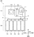
- Fig. 1 is a diagram illustrating an internal configuration of the automated transaction apparatus 100 (at the time of deposits).
- Fig. 2 is a diagram illustrating an internal configuration of the automated transaction apparatus 100 (at the time of withdrawals).
- each of the upward/downward, forward/backward, and leftward/rightward directions illustrated in Figs. 1 and 2 and Figs. 3 to 7 described below is only an example in a case where it is assumed that a customer side of the automated transaction apparatus 100 is a forward direction.
- the upward/downward direction is a vertical direction
- the forward/backward direction and the leftward/rightward direction are horizontal directions.
- the automated transaction apparatus 100 illustrated in Figs. 1 and 2 is, for example, an ATM, a bill recycle unit (BRU), a cash dispenser (CD), a teller cash recycler (TCR), or the like, and includes the conveyance route switching mechanism 1, a body 110, and a storage 120.
- Banknote B that is an example of a paper sheet is conveyed through a conveyance path T in the automated transaction apparatus 100.
- the conveyance route switching mechanism 1 is disposed in a position where three conveyance paths in total, for example, a first conveyance path T1 and a second conveyance path T2 that connect the body 110 and the storage 120, and a third conveyance path T3 that is connected to banknote storage cassettes 122 to 125, cross each other on the conveyance path T in the automated transaction apparatus 100.
- the conveyance route switching mechanism 1 can be disposed in an arbitrary position where three or more conveyance paths cross each other.
- the body 110 includes a banknote deposit/withdrawal part 111, a discrimination part 112, and a temporary holding part 113.
- banknote B that is an example of a paper sheet is inserted into the banknote deposit/withdrawal part 111, and at the time of withdrawals, banknote B is ejected from the banknote deposit/withdrawal part 111.
- the discrimination part 112 determines authenticity, stains, corner folding, or the like of banknote B.
- the temporary holding part 113 temporarily stores banknote B that the discrimination part 112 has determined to be normal, for example, by winding up the banknote B.
- the storage 120 includes a reject part 121 and a plurality of banknote storage cassettes 122 to 125.
- the reject part 121 stores, for example, banknote B that will not be returned from among pieces of banknote B that the discrimination part 112 has determined to be abnormal.
- the banknote storage cassettes 122 to 125 store, for example, pieces of banknote B that are different in type from each other.
- the banknote storage cassettes 122 to 125 can eject stored banknote B. Therefore, banknote B stored in the banknote storage cassettes 122 to 125 is used for withdrawals.
- banknote B that has been inserted into the banknote deposit/withdrawal part 111 is conveyed to the discrimination part 112. Then, banknote B that the discrimination part 112 has determined to be normal is conveyed to the temporary holding part 113.
- This banknote B that is temporarily stored in the temporary holding part 113 is conveyed through the first conveyance path T1 and the third conveyance path T3 to any of the banknote storage cassettes 122 to 125.
- banknote B (counterfeit banknote or the like) that the discrimination part 112 has determined to be abnormal is not conveyed to the temporary holding part 113, but is conveyed through the first conveyance path T1 to the reject part 121.
- banknote B stored in the banknote storage cassettes 122 to 125 is conveyed through the first conveyance path T1 or the second conveyance path T2 and the discrimination part 112 to the paper money deposit/withdrawal part 111.
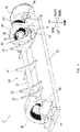
- Fig. 3 is a perspective view of the conveyance route switching mechanism 1 when viewed from the above of a right rear side.
- Fig. 4 is a perspective view of the conveyance route switching mechanism 1 when viewed from the above of a left front side.
- the conveyance route switching mechanism 1 includes a driving source 10, a gate 20, a pair of first gears 30, a pair of internal gears 40, a second gear 50, a third gear 60, and a base 70.
- the driving source 10 is an actuator that includes a driving shaft 11, and is, for example, a rotary solenoid that rotates (swings) the driving shaft 11 within a range of a predetermined angle.
- the gate 20 includes a gate shaft 21 and, for example, five blades 22 that are provided on this gate shaft 21, and the gate 20 switches conveyance routes of banknote B.
- the gate shaft 21 extends in the leftward/rightward direction. At a right-hand end of the gate shaft 21, the third gear 60 is provided, and near a left-hand end and the right-hand end of the gate shaft 21, the pair of first gears 30 are provided.
- One blade 22 of the five blades 22 is provided in a center in a width direction (the leftward/rightward direction) of a conveyance path T that is not illustrated in Figs. 3 and 4 on the gate shaft 21. From among four other blades 22, two blades are provided on a side of a left-hand end of the conveyance path T, and two blades are provided on a side of a right-hand end of the conveyance path T on the gate shaft 21.
- the blade 22 has, for example, a triangular plate shape having two sides recessed inward from among three sides.
- the blade 22 guides banknote B in a circumference (for example, the three sides).
- the shapes of the blades 22 illustrated in Figs. 3 and 4 are slightly different from the shapes of the blades 22 illustrated in Figs. 5 to 7 described below.
- the blade 22 can have an arbitrary shape, and therefore the blade 22 may have any shape.
- Each of the pair of first gears 30 is, for example, a spur gear, and is provided near the left-hand end or the right-hand end of the gate shaft 21, as described above.
- the pair of first gears 30 mesh with the pair of internal gears 40.
- the pair of internal gears 40 are disposed to face each other in the leftward/rightward direction.
- Each of the pair of internal gears 40 is provided with teeth 41 within a range of about 90 degrees, and has a fan shape. Note that the internal gear 40 can have a fan shape if the teeth 41 are provided within a range that is less than 180 degrees.
- an internal gear 40 on a side of the driving source 10 (on a right-hand side) includes a bearing 42 that rotatably supports the driving shaft 11.
- the second gear 50 is, for example, a spur gear that is provided on the driving shaft 11.
- the third gear 60 is, for example, a spur gear that is provided at the right-hand end of the gate shaft 21, and meshes with the second gear 50.
- the base 70 has a flat plate shape, and the pair of internal gears 40 are fixed at both left-hand and right-hand ends of an upper face of the base 70.
- the base 70 is disposed to be unable to move, and therefore the internal gears 40 that are fixed to this base 70 are also disposed to be unable to move.
- the second gear 50 that is provided on the driving shaft 11 meshes with the third gear 60 that is provided at the right-hand end of the gate shaft 21.
- the second gear 50 may mesh with the first gear 30 that is provided on the gate shaft 21.
- the third gear 60 can be omitted. This causes the driving source 10 to be closer to the internal gear 40 on a right-hand side, and the space of the conveyance route switching mechanism 1 can be saved.
- the second gear 50 that is provided on the driving shaft 11 meshes with the third gear 60 that is provided on the gate shaft 21, and therefore the gate shaft 21 rotates on its axis according to the rotation of the driving shaft 11.
- the second gear 50 and the third gear 60 can be omitted.
- Fig. 5 is a diagram for explaining switching of conveyance routes.
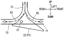
- Fig. 6 is a diagram illustrating a blade 22 that is located in a first position P1.
- Fig. 7 is a diagram illustrating a blade 22 that is located in a second position P2.
- the gate shaft 21 According to the rotation of the gate shaft 21 on its axis, the pair of first gears 30 that are provided on this gate shaft 21 rotate. Therefore, according to the rotation of the driving shaft 11, the gate shaft 21 revolves along the revolution orbit R illustrated in Fig. 5 with the driving shaft 11 as a rotation center, while the pair of first gears 30 mesh with the pair of internal gears 40.
- the second gear 50 that is provided on the driving shaft 11 serving as the rotation center of the revolution orbit R functions as a sun gear
- the first gears 30 and the third gear 60 function as planetary gears.
- the blade 22 in a position where the first conveyance path T1, the second conveyance path T2, and the third conveyance path T3 cross each other, the blade 22 can move to the first position P1, and the second position P2 where the gate shaft 21 has rotated on its axis counterclockwise in Fig. 5 from the first position P1, and has revolved along the revolution orbit R clockwise in Fig. 5 .
- the blade 22 that is located in the first position P1 illustrated in Fig. 6 switches a conveyance route in such a way that the second conveyance path T2 is connected to the first conveyance path T1 and the third conveyance path T3. Therefore, banknote B to be conveyed through the third conveyance path T3 can be conveyed to the second conveyance path T2 in a conveyance direction D1, and banknote B to be conveyed through the first conveyance path T1 can be conveyed to the second conveyance path T2 in a conveyance direction D2.
- banknote B to be conveyed from the reject part 121 through the first conveyance path T1 and banknote B to be conveyed from the banknote storage cassettes 122 to 125 through the third conveyance path T3 can be conveyed through the second conveyance path T2 to a side of the body 110 illustrated in Figs. 1 and 2 .
- the blade 22 that is located in the second position P2 illustrated in Fig. 7 switches a conveyance route in such a way that the third conveyance path T3 is connected to the first conveyance path T1 and the second conveyance path T2. Therefore, banknote B to be conveyed through the first conveyance path T1 can be conveyed to the third conveyance path T3 in a conveyance direction D3, and banknote B to be conveyed through the second conveyance path T2 can be conveyed to the third conveyance path T3 in a conveyance direction D4.
- banknote B to be conveyed through the first conveyance path T1 and banknote B to be conveyed through the second conveyance path T2 can be conveyed through the third conveyance path T2 to the banknote storage cassettes 122 to 125.
- the blade 22 is located in the first position P1 illustrated in Fig. 6 to guide, to the second conveyance path T2 in the conveyance direction D1, banknote B to be conveyed from the banknote storage cassettes 122 to 125 through the third conveyance path T3 in such a way that the banknote B will advance to a side of the body 110. This causes the banknote B to be conveyed to the body 110.
- a certain number of pieces of banknote B that has been counted by the discrimination part 112 are conveyed from the side of the body 110 through the first conveyance path T1 to the reject part 121.
- the blade 22 is located in the second position P2 illustrated in Fig. 7 to guide banknote B stored in the reject part 121 in such a way that the banknote B will be conveyed through the first conveyance path T1 and the third conveyance path T3 to the banknote storage cassettes 122 to 125 in the conveyance direction D3.
- a conveyance route switching mechanism 1 and an automated transaction apparatus 100 that includes this conveyance route switching mechanism 1 and is an example of a paper sheet handling apparatus include a driving source 10, a gate 20, a first gear 30, and an internal gear 40.
- the driving source 10 includes a driving shaft 11.
- the gate 20 includes a gate shaft 21 and a blade 22 that is provided on this gate shaft 21, and switches conveyance routes of banknote B that is an example of a paper sheet.
- the first gear 30 is provided on the gate shaft 21.
- the internal gear 40 meshes with the first gear 30. According to the rotation of the driving shaft 11, the gate shaft 21 rotates on its axis, and revolves with the driving shaft 11 as a rotation center while the first gear 30 and the internal gear 40 mesh with each other.
- the blade 22 that is provided on the gate shaft 21 can move due to the rotation and revolution of the gate shaft 21.
- angles of the rotation and revolution of the gate shaft 21 or a revolution orbit R change according to a module (a value obtained by dividing a diameter of a pitch circle by the number of teeth) or a gear ratio of the first gear 30 and the internal gear 40, and therefore design having a high degree of freedom can be achieved.
- conveyance routes can be complicatedly switched, for example, in such a way that in a position where a first conveyance path T1, a second conveyance path T2, and a third conveyance path T3 cross each other, switching is performed between a conveyance route that connects one conveyance path (for example, the second conveyance path T2) and two remaining conveyance paths (for example, the first conveyance path T1 and the third conveyance path T3) and a conveyance route that connects another conveyance path (for example, the third conveyance path T3) and two remaining conveyance paths (for example, the first conveyance path T1 and the second conveyance path T2).
- conveyance routes can be arbitrarily switched in a space-saving configuration.
- the conveyance route switching mechanism 1 further includes a second gear 50 that is provided on the driving shaft 11, and a third gear 60 that is provided on the gate shaft 21 and meshes with the second gear 50.
- the internal gear 40 is provided with teeth 41 that mesh with the first gear 30 within a range that is less than 180 degrees, and has a fan shape.
Landscapes
- Engineering & Computer Science (AREA)
- Mechanical Engineering (AREA)
- Separation, Sorting, Adjustment, Or Bending Of Sheets To Be Conveyed (AREA)
- Feeding Of Articles By Means Other Than Belts Or Rollers (AREA)
Abstract
Description
- The present invention relates to a conveyance route switching mechanism and a paper sheet handling apparatus.
- Conventionally, a conveyance switching apparatus has been proposed where one driving means causes two conveyance switching blades to be interlocked with each other and rotate in a merging part where three conveyance paths merge (see, for example, Patent Literature 1).
- Patent Literature 1:
JP 2016-147751 A - In a paper sheet handling apparatus such as an automated teller machine (ATM), conveyance routes of paper sheets are complicatedly switched, for example, in such a way that in a position where three conveyance paths cross each other, a conveyance route is switched between a conveyance route that connects one conveyance path and two remaining conveyance paths and a conveyance route that connects another conveyance path and two remaining conveyance paths, and therefore the number of conveyance paths can be reduced in the paper sheet handling apparatus. This enables space saving.
- However, in order to complicatedly switch conveyance routes, as described above, in a position where three conveyance paths cross each other, a plurality of gates is combined and used. Therefore, space fails to be saved from the point of view of the use of a plurality of gates.
- For example, in the conveyance switching apparatus described above, one driving means is used. However, two conveyance switching blades are used, and therefore space fails to be saved. Further, in the conveyance switching apparatus described above, one driving means causes two conveyance switching blades to be interlocked with each other, and therefore conveyance routes fail to be complicatedly switched, as described above, in a position where three conveyance paths cross each other.
- It is an object of the present invention to provide a conveyance route switching mechanism and a paper sheet handling apparatus that are capable of arbitrarily switching conveyance routes in a space-saving configuration.
- A conveyance route switching mechanism of the disclosure includes a driving source, a gate, a first gear, and an internal gear. The driving source includes a driving shaft. The gate includes a gate shaft, and a blade that is provided on the gate shaft, and switches conveyance routes of paper sheets. The first gear is provided on the gate shaft. The internal gear meshes with the first gear. According to rotation of the driving shaft, the gate shaft rotates on an axis of the gate shaft, and revolves with the driving shaft as a rotation center while the first gear meshes with the internal gear.
- A paper sheet handling apparatus of the disclosure is a paper sheet handling apparatus that includes a conveyance route switching mechanism, and the conveyance route switching mechanism includes a driving source, a gate, a first gear, and an internal gear. The driving source includes a driving shaft. The gate includes a gate shaft, and a blade that is provided on the gate shaft, and switches conveyance routes of paper sheets. The first gear is provided on the gate shaft. The internal gear meshes with the first gear. According to rotation of the driving shaft, the gate shaft rotates on an axis of the gate shaft, and revolves with the driving shaft as a rotation center while the first gear meshes with the internal gear.
- A conveyance route switching mechanism and a paper sheet handling apparatus of the disclosure enable conveyance routes to be arbitrarily switched in a space-saving configuration.
-
-
Fig. 1 is a diagram illustrating an internal configuration of an automated transaction apparatus according to an embodiment (at the time of deposits). -
Fig. 2 is a diagram illustrating an internal configuration of an automated transaction apparatus according to an embodiment (at the time of withdrawals). -
Fig. 3 is a perspective view of a conveyance route switching mechanism according to an embodiment when viewed from the above of a right rear side. -
Fig. 4 is a perspective view of a conveyance route switching mechanism according to an embodiment when viewed from the above of a left front side. -
Fig. 5 is a diagram for explaining switching of conveyance routes according to an embodiment. -
Fig. 6 is a diagram illustrating a blade that is located in a first position according to an embodiment. -
Fig. 7 is a diagram illustrating a blade that is located in a second position according to an embodiment. - A conveyance route switching mechanism and a paper sheet handling apparatus according to an embodiment of the present invention are described below with reference to the drawings by using, as an example, a conveyance
route switching mechanism 1 and anautomated transaction apparatus 100. -
Fig. 1 is a diagram illustrating an internal configuration of the automated transaction apparatus 100 (at the time of deposits). -
Fig. 2 is a diagram illustrating an internal configuration of the automated transaction apparatus 100 (at the time of withdrawals). - Note that each of the upward/downward, forward/backward, and leftward/rightward directions illustrated in
Figs. 1 and2 andFigs. 3 to 7 described below is only an example in a case where it is assumed that a customer side of theautomated transaction apparatus 100 is a forward direction. However, for example, the upward/downward direction is a vertical direction, and the forward/backward direction and the leftward/rightward direction are horizontal directions. - The
automated transaction apparatus 100 illustrated inFigs. 1 and2 is, for example, an ATM, a bill recycle unit (BRU), a cash dispenser (CD), a teller cash recycler (TCR), or the like, and includes the conveyanceroute switching mechanism 1, abody 110, and astorage 120. Banknote B that is an example of a paper sheet is conveyed through a conveyance path T in theautomated transaction apparatus 100. - Details of the conveyance
route switching mechanism 1 will be described below, but the conveyanceroute switching mechanism 1 is disposed in a position where three conveyance paths in total, for example, a first conveyance path T1 and a second conveyance path T2 that connect thebody 110 and thestorage 120, and a third conveyance path T3 that is connected tobanknote storage cassettes 122 to 125, cross each other on the conveyance path T in theautomated transaction apparatus 100. Note that the conveyanceroute switching mechanism 1 can be disposed in an arbitrary position where three or more conveyance paths cross each other. - The
body 110 includes a banknote deposit/withdrawal part 111, adiscrimination part 112, and atemporary holding part 113. - At the time of deposits, banknote B that is an example of a paper sheet is inserted into the banknote deposit/
withdrawal part 111, and at the time of withdrawals, banknote B is ejected from the banknote deposit/withdrawal part 111. - The
discrimination part 112 determines authenticity, stains, corner folding, or the like of banknote B. - The
temporary holding part 113 temporarily stores banknote B that thediscrimination part 112 has determined to be normal, for example, by winding up the banknote B. - The
storage 120 includes areject part 121 and a plurality ofbanknote storage cassettes 122 to 125. - The reject
part 121 stores, for example, banknote B that will not be returned from among pieces of banknote B that thediscrimination part 112 has determined to be abnormal. - The
banknote storage cassettes 122 to 125 store, for example, pieces of banknote B that are different in type from each other. Thebanknote storage cassettes 122 to 125 can eject stored banknote B. Therefore, banknote B stored in thebanknote storage cassettes 122 to 125 is used for withdrawals. - As an example, at the time of deposits illustrated in
Fig. 1 , banknote B that has been inserted into the banknote deposit/withdrawal part 111 is conveyed to thediscrimination part 112. Then, banknote B that thediscrimination part 112 has determined to be normal is conveyed to thetemporary holding part 113. This banknote B that is temporarily stored in thetemporary holding part 113 is conveyed through the first conveyance path T1 and the third conveyance path T3 to any of thebanknote storage cassettes 122 to 125. In contrast, banknote B (counterfeit banknote or the like) that thediscrimination part 112 has determined to be abnormal is not conveyed to thetemporary holding part 113, but is conveyed through the first conveyance path T1 to thereject part 121. - In addition, at the time of withdrawals illustrated in
Fig. 2 , banknote B stored in thebanknote storage cassettes 122 to 125 is conveyed through the first conveyance path T1 or the second conveyance path T2 and thediscrimination part 112 to the paper money deposit/withdrawal part 111. -
Fig. 3 is a perspective view of the conveyanceroute switching mechanism 1 when viewed from the above of a right rear side. -
Fig. 4 is a perspective view of the conveyanceroute switching mechanism 1 when viewed from the above of a left front side. - The conveyance
route switching mechanism 1 includes adriving source 10, agate 20, a pair offirst gears 30, a pair ofinternal gears 40, asecond gear 50, athird gear 60, and abase 70. - The
driving source 10 is an actuator that includes adriving shaft 11, and is, for example, a rotary solenoid that rotates (swings) thedriving shaft 11 within a range of a predetermined angle. - The
gate 20 includes agate shaft 21 and, for example, fiveblades 22 that are provided on thisgate shaft 21, and thegate 20 switches conveyance routes of banknote B. - The
gate shaft 21 extends in the leftward/rightward direction. At a right-hand end of thegate shaft 21, thethird gear 60 is provided, and near a left-hand end and the right-hand end of thegate shaft 21, the pair offirst gears 30 are provided. - One
blade 22 of the fiveblades 22 is provided in a center in a width direction (the leftward/rightward direction) of a conveyance path T that is not illustrated inFigs. 3 and4 on thegate shaft 21. From among fourother blades 22, two blades are provided on a side of a left-hand end of the conveyance path T, and two blades are provided on a side of a right-hand end of the conveyance path T on thegate shaft 21. - The
blade 22 has, for example, a triangular plate shape having two sides recessed inward from among three sides. Theblade 22 guides banknote B in a circumference (for example, the three sides). Note that the shapes of theblades 22 illustrated inFigs. 3 and4 are slightly different from the shapes of theblades 22 illustrated inFigs. 5 to 7 described below. However, theblade 22 can have an arbitrary shape, and therefore theblade 22 may have any shape. - Each of the pair of
first gears 30 is, for example, a spur gear, and is provided near the left-hand end or the right-hand end of thegate shaft 21, as described above. The pair offirst gears 30 mesh with the pair ofinternal gears 40. - The pair of
internal gears 40 are disposed to face each other in the leftward/rightward direction. Each of the pair ofinternal gears 40 is provided withteeth 41 within a range of about 90 degrees, and has a fan shape. Note that theinternal gear 40 can have a fan shape if theteeth 41 are provided within a range that is less than 180 degrees. - From among the pair of
internal gears 40, aninternal gear 40 on a side of the driving source 10 (on a right-hand side) includes abearing 42 that rotatably supports the drivingshaft 11. - The
second gear 50 is, for example, a spur gear that is provided on the drivingshaft 11. - The
third gear 60 is, for example, a spur gear that is provided at the right-hand end of thegate shaft 21, and meshes with thesecond gear 50. - The
base 70 has a flat plate shape, and the pair ofinternal gears 40 are fixed at both left-hand and right-hand ends of an upper face of thebase 70. Thebase 70 is disposed to be unable to move, and therefore theinternal gears 40 that are fixed to thisbase 70 are also disposed to be unable to move. - In the conveyance
route switching mechanism 1 described above, thesecond gear 50 that is provided on the drivingshaft 11 meshes with thethird gear 60 that is provided at the right-hand end of thegate shaft 21. However, thesecond gear 50 may mesh with thefirst gear 30 that is provided on thegate shaft 21. In this case, thethird gear 60 can be omitted. This causes the drivingsource 10 to be closer to theinternal gear 40 on a right-hand side, and the space of the conveyanceroute switching mechanism 1 can be saved. - In addition, the
second gear 50 that is provided on the drivingshaft 11 meshes with thethird gear 60 that is provided on thegate shaft 21, and therefore thegate shaft 21 rotates on its axis according to the rotation of the drivingshaft 11. For example, in a case where the drivingshaft 11 and thegate shaft 21 are coupled by a power transmission means such as a belt, thesecond gear 50 and thethird gear 60 can be omitted. - Switching of conveyance routes of the conveyance
route switching mechanism 1 is described below. -
Fig. 5 is a diagram for explaining switching of conveyance routes. -
Fig. 6 is a diagram illustrating ablade 22 that is located in a first position P1. -
Fig. 7 is a diagram illustrating ablade 22 that is located in a second position P2. - First, in the conveyance
route switching mechanism 1 illustrated inFigs. 3 and4 , when the drivingsource 10 rotates the drivingshaft 11, thesecond gear 50 that is provided on this drivingshaft 11 rotates. In addition, thethird gear 60 that meshes with thissecond gear 50 rotates, and therefore thegate shaft 21 that is provided with thethird gear 60 rotates. As described above, thegate shaft 21 rotates on its axis according to the rotation of the drivingshaft 11. - In addition, according to the rotation of the
gate shaft 21 on its axis, the pair offirst gears 30 that are provided on thisgate shaft 21 rotate. Therefore, according to the rotation of the drivingshaft 11, thegate shaft 21 revolves along the revolution orbit R illustrated inFig. 5 with the drivingshaft 11 as a rotation center, while the pair offirst gears 30 mesh with the pair ofinternal gears 40. As described above, thesecond gear 50 that is provided on the drivingshaft 11 serving as the rotation center of the revolution orbit R functions as a sun gear, and thefirst gears 30 and thethird gear 60 function as planetary gears. - By doing this, as illustrated in
Fig. 5 , in a position where the first conveyance path T1, the second conveyance path T2, and the third conveyance path T3 cross each other, theblade 22 can move to the first position P1, and the second position P2 where thegate shaft 21 has rotated on its axis counterclockwise inFig. 5 from the first position P1, and has revolved along the revolution orbit R clockwise inFig. 5 . - The
blade 22 that is located in the first position P1 illustrated inFig. 6 switches a conveyance route in such a way that the second conveyance path T2 is connected to the first conveyance path T1 and the third conveyance path T3. Therefore, banknote B to be conveyed through the third conveyance path T3 can be conveyed to the second conveyance path T2 in a conveyance direction D1, and banknote B to be conveyed through the first conveyance path T1 can be conveyed to the second conveyance path T2 in a conveyance direction D2. - By doing this, for example, in a case where a jam has occurred in part of the first conveyance path T1 or in other cases, banknote B to be conveyed from the
reject part 121 through the first conveyance path T1 and banknote B to be conveyed from thebanknote storage cassettes 122 to 125 through the third conveyance path T3 can be conveyed through the second conveyance path T2 to a side of thebody 110 illustrated inFigs. 1 and2 . - In addition, the
blade 22 that is located in the second position P2 illustrated inFig. 7 switches a conveyance route in such a way that the third conveyance path T3 is connected to the first conveyance path T1 and the second conveyance path T2. Therefore, banknote B to be conveyed through the first conveyance path T1 can be conveyed to the third conveyance path T3 in a conveyance direction D3, and banknote B to be conveyed through the second conveyance path T2 can be conveyed to the third conveyance path T3 in a conveyance direction D4. - By doing this, banknote B to be conveyed through the first conveyance path T1 and banknote B to be conveyed through the second conveyance path T2 can be conveyed through the third conveyance path T2 to the
banknote storage cassettes 122 to 125. - Alternatively, in a case where the number of pieces of banknote B stored in each of the
banknote storage cassettes 122 to 125 is counted by thediscrimination part 112, and a counted number of pieces of banknote B are temporarily stored in thereject part 121 in an empty state, theblade 22 is located in the first position P1 illustrated inFig. 6 to guide, to the second conveyance path T2 in the conveyance direction D1, banknote B to be conveyed from thebanknote storage cassettes 122 to 125 through the third conveyance path T3 in such a way that the banknote B will advance to a side of thebody 110. This causes the banknote B to be conveyed to thebody 110. - Then, a certain number of pieces of banknote B that has been counted by the
discrimination part 112 are conveyed from the side of thebody 110 through the first conveyance path T1 to thereject part 121. In addition, after the counting of the number of pieces of banknote B has been finished, theblade 22 is located in the second position P2 illustrated inFig. 7 to guide banknote B stored in thereject part 121 in such a way that the banknote B will be conveyed through the first conveyance path T1 and the third conveyance path T3 to thebanknote storage cassettes 122 to 125 in the conveyance direction D3. - In the present embodiment described above, a conveyance
route switching mechanism 1 and anautomated transaction apparatus 100 that includes this conveyanceroute switching mechanism 1 and is an example of a paper sheet handling apparatus include a drivingsource 10, agate 20, afirst gear 30, and aninternal gear 40. The drivingsource 10 includes a drivingshaft 11. Thegate 20 includes agate shaft 21 and ablade 22 that is provided on thisgate shaft 21, and switches conveyance routes of banknote B that is an example of a paper sheet. Thefirst gear 30 is provided on thegate shaft 21. Theinternal gear 40 meshes with thefirst gear 30. According to the rotation of the drivingshaft 11, thegate shaft 21 rotates on its axis, and revolves with the drivingshaft 11 as a rotation center while thefirst gear 30 and theinternal gear 40 mesh with each other. - By doing this, the
blade 22 that is provided on thegate shaft 21 can move due to the rotation and revolution of thegate shaft 21. In addition, angles of the rotation and revolution of thegate shaft 21 or a revolution orbit R change according to a module (a value obtained by dividing a diameter of a pitch circle by the number of teeth) or a gear ratio of thefirst gear 30 and theinternal gear 40, and therefore design having a high degree of freedom can be achieved. Therefore, conveyance routes can be complicatedly switched, for example, in such a way that in a position where a first conveyance path T1, a second conveyance path T2, and a third conveyance path T3 cross each other, switching is performed between a conveyance route that connects one conveyance path (for example, the second conveyance path T2) and two remaining conveyance paths (for example, the first conveyance path T1 and the third conveyance path T3) and a conveyance route that connects another conveyance path (for example, the third conveyance path T3) and two remaining conveyance paths (for example, the first conveyance path T1 and the second conveyance path T2). Accordingly, by making it complicated to switch conveyance routes, the number of conveyance paths in theautomated transaction apparatus 100 is reduced, and this enables a reduction in a cost and space saving. Moreover, a single conveyanceroute switching mechanism 1 can switch conveyance routes, and this enables a reduction in a cost and further space saving. Therefore, according to the present embodiment, conveyance routes can be arbitrarily switched in a space-saving configuration. - In addition, in the present embodiment, the conveyance
route switching mechanism 1 further includes asecond gear 50 that is provided on the drivingshaft 11, and athird gear 60 that is provided on thegate shaft 21 and meshes with thesecond gear 50. - This enables design having a higher degree of freedom by adjusting a module or a gear ratio of the
second gear 50 and thethird gear 60, in comparison with, for example, an aspect where thethird gear 60 is omitted, and thesecond gear 50 meshes with thefirst gear 30. - In addition, in the present embodiment, the
internal gear 40 is provided withteeth 41 that mesh with thefirst gear 30 within a range that is less than 180 degrees, and has a fan shape. - This enables a reduction in size of the
internal gear 40 in comparison with an aspect where a circular internal gear is used, and therefore further space saving can be achieved. - Note that the present invention is not limited to the embodiment described above with no change, and components can be varied and embodied. For example, various inventions can be made by appropriately combining the plurality of components disclosed in the present embodiment. As described above, various variations or applications of the invention can be made without departing from the spirit of the invention.
-
- 1
- Conveyance route switching mechanism
- 10
- Driving source
- 11
- Driving shaft
- 20
- Gate
- 21
- Gate shaft
- 22
- Blade
- 30
- First gear
- 40
- Internal gear
- 41
- Tooth
- 42
- Bearing
- 50
- Second gear
- 60
- Third gear
- 70
- Base
- 100
- Automated transaction apparatus
- 110
- Body
- 111
- Banknote deposit/withdrawal part
- 112
- Discrimination part
- 113
- Temporary holding part
- 120
- Storage
- 121
- Reject part
- 122 to 125
- Banknote storage cassette
- B
- Banknote
- D1 to D4
- Conveyance direction
- P1
- First position
- P2
- Second position
- R
- Revolution orbit
- T
- Conveyance path
- T1
- First conveyance path
- T2
- Second conveyance path
- T3
- Third conveyance path
Claims (4)
- A conveyance route switching mechanism comprising:a driving source that includes a driving shaft;a gate that includes a gate shaft, and a blade that is provided on the gate shaft, the gate switching conveyance routes of paper sheets;a first gear that is provided on the gate shaft; andan internal gear that meshes with the first gear, whereinaccording to rotation of the driving shaft, the gate shaft rotates on an axis of the gate shaft, and revolves with the driving shaft as a rotation center while the first gear meshes with the internal gear.
- The conveyance route switching mechanism according to claim 1, further comprising:a second gear that is provided on the driving shaft; anda third gear that is provided on the gate shaft, and meshes with the second gear.
- The conveyance route switching mechanism according to claim 1 or 2, wherein the internal gear is provided with teeth within a range that is less than 180 degrees, the teeth meshing with the first gear, and the internal gear has a fan shape.
- A paper sheet handling apparatus comprising a conveyance route switching mechanism, wherein
the conveyance route switching mechanism includes:a driving source that includes a driving shaft;a gate that includes a gate shaft, and a blade that is provided on the gate shaft, the gate switching conveyance routes of paper sheets;a first gear that is provided on the gate shaft; andan internal gear that meshes with the first gear, andaccording to rotation of the driving shaft, the gate shaft rotates on an axis of the gate shaft, and revolves with the driving shaft as a rotation center while the first gear meshes with the internal gear.
Applications Claiming Priority (1)
| Application Number | Priority Date | Filing Date | Title |
|---|---|---|---|
| PCT/JP2020/012132 WO2021186647A1 (en) | 2020-03-18 | 2020-03-18 | Conveyance path switching mechanism, and paper sheet handling device |
Publications (3)
| Publication Number | Publication Date |
|---|---|
| EP4122852A1 true EP4122852A1 (en) | 2023-01-25 |
| EP4122852A4 EP4122852A4 (en) | 2023-12-13 |
| EP4122852B1 EP4122852B1 (en) | 2024-11-20 |
Family
ID=77771742
Family Applications (1)
| Application Number | Title | Priority Date | Filing Date |
|---|---|---|---|
| EP20925695.7A Active EP4122852B1 (en) | 2020-03-18 | 2020-03-18 | Conveyance path switching mechanism, and paper sheet handling device |
Country Status (5)
| Country | Link |
|---|---|
| US (1) | US11964839B2 (en) |
| EP (1) | EP4122852B1 (en) |
| JP (1) | JP7212203B2 (en) |
| CN (1) | CN115315397A (en) |
| WO (1) | WO2021186647A1 (en) |
Family Cites Families (14)
| Publication number | Priority date | Publication date | Assignee | Title |
|---|---|---|---|---|
| JP3330822B2 (en) * | 1996-06-26 | 2002-09-30 | 株式会社ピーエフユー | Medium processing apparatus and control method thereof |
| US5927713A (en) * | 1997-09-18 | 1999-07-27 | Bell & Howell Mail Processing Systems | Apparatus and method for inverting, staging and diverting sheet articles |
| EP1873726A4 (en) * | 2005-03-29 | 2010-07-07 | Glory Kogyo Kk | Banknote handling device |
| JP4700598B2 (en) * | 2006-12-19 | 2011-06-15 | 沖電気工業株式会社 | Paper sheet transport path switching gate and automatic cash transaction equipment |
| US7594655B2 (en) * | 2007-06-26 | 2009-09-29 | Foxline Image Technology Co., Ltd. | Paper feed apparatus for duplex printing apparatus |
| JP5172257B2 (en) * | 2007-09-12 | 2013-03-27 | グローリー株式会社 | Paper sheet branching mechanism, paper sheet processing apparatus, and paper sheet branching method |
| CN102583089B (en) * | 2011-01-11 | 2015-11-25 | 山东新北洋信息技术股份有限公司 | Laminated medium processing unit |
| JP2013041451A (en) * | 2011-08-17 | 2013-02-28 | Oki Electric Ind Co Ltd | Sheet paper conveyance device and automatic teller machine |
| JP6071971B2 (en) * | 2013-10-18 | 2017-02-01 | キヤノン株式会社 | Sheet conveying apparatus and image forming apparatus |
| JP6381129B2 (en) * | 2015-02-13 | 2018-08-29 | ローレルバンクマシン株式会社 | Paper sheet transfer switching device |
| KR101781686B1 (en) * | 2015-07-21 | 2017-10-23 | 주식회사 엘지씨엔에스 | Diverter, medium processing apparatus and financial device |
| CN207068102U (en) * | 2017-06-30 | 2018-03-02 | 深圳怡化电脑股份有限公司 | Automatic trading apparatus and its paper currency transmission switching device |
| JP7237510B2 (en) * | 2017-10-30 | 2023-03-13 | キヤノン株式会社 | sheet conveying device |
| US10703594B2 (en) | 2017-10-30 | 2020-07-07 | Canon Kabushiki Kaisha | Sheet conveyance apparatus |
-
2020
- 2020-03-18 WO PCT/JP2020/012132 patent/WO2021186647A1/en not_active Ceased
- 2020-03-18 EP EP20925695.7A patent/EP4122852B1/en active Active
- 2020-03-18 JP JP2022507938A patent/JP7212203B2/en active Active
- 2020-03-18 CN CN202080098677.7A patent/CN115315397A/en active Pending
-
2022
- 2022-09-08 US US17/930,580 patent/US11964839B2/en active Active
Also Published As
| Publication number | Publication date |
|---|---|
| US11964839B2 (en) | 2024-04-23 |
| CN115315397A (en) | 2022-11-08 |
| EP4122852B1 (en) | 2024-11-20 |
| EP4122852A4 (en) | 2023-12-13 |
| JP7212203B2 (en) | 2023-01-24 |
| US20230002182A1 (en) | 2023-01-05 |
| JPWO2021186647A1 (en) | 2021-09-23 |
| WO2021186647A1 (en) | 2021-09-23 |
Similar Documents
| Publication | Publication Date | Title |
|---|---|---|
| US8857598B2 (en) | Paper sheet conveying device and automatic cash transaction device | |
| JPH0198553A (en) | Sheet treater | |
| EP2259233A1 (en) | Paper note handling apparatus and method for handling paper notes | |
| US11640740B2 (en) | Automated teller machine and medium conveyance route switching device for automated teller machine | |
| RU2746304C1 (en) | Media processing device and automatic device for executing transactions | |
| JP2531226Y2 (en) | Banknote storage mechanism | |
| JP2013041451A5 (en) | ||
| US9352925B2 (en) | Position adjustment device and paper sheet processing device | |
| EP4122852B1 (en) | Conveyance path switching mechanism, and paper sheet handling device | |
| JP6089693B2 (en) | Take-out and feeding device, medium storage, and medium handling device | |
| US12536858B2 (en) | Paper sheet handling apparatus | |
| WO2016194534A1 (en) | Driving force transmission device and medium processing device | |
| JP6064786B2 (en) | Medium stacking apparatus and medium processing apparatus | |
| US12444262B2 (en) | Paper sheet handling apparatus | |
| JP6405928B2 (en) | Actuator and medium transaction device | |
| WO2015093374A1 (en) | Paper currency processing device | |
| JP6511764B2 (en) | Medium storage device and medium transaction device | |
| US7575155B2 (en) | Rotating path switch | |
| JP7840627B2 (en) | Paper handling equipment | |
| JPH04278693A (en) | Posture converter and transport processor of papers | |
| WO2023119492A1 (en) | Guide mechanism and paper-sheet handling device | |
| WO2022176081A1 (en) | Paper sheet handling device | |
| JPS59102750A (en) | Paper sheet reversing device | |
| JP2020057036A (en) | Paper handling equipment, automatic transaction equipment, and paper sorting equipment |
Legal Events
| Date | Code | Title | Description |
|---|---|---|---|
| STAA | Information on the status of an ep patent application or granted ep patent |
Free format text: STATUS: THE INTERNATIONAL PUBLICATION HAS BEEN MADE |
|
| PUAI | Public reference made under article 153(3) epc to a published international application that has entered the european phase |
Free format text: ORIGINAL CODE: 0009012 |
|
| STAA | Information on the status of an ep patent application or granted ep patent |
Free format text: STATUS: REQUEST FOR EXAMINATION WAS MADE |
|
| 17P | Request for examination filed |
Effective date: 20220916 |
|
| AK | Designated contracting states |
Kind code of ref document: A1 Designated state(s): AL AT BE BG CH CY CZ DE DK EE ES FI FR GB GR HR HU IE IS IT LI LT LU LV MC MK MT NL NO PL PT RO RS SE SI SK SM TR |
|
| DAV | Request for validation of the european patent (deleted) | ||
| DAX | Request for extension of the european patent (deleted) | ||
| A4 | Supplementary search report drawn up and despatched |
Effective date: 20231113 |
|
| RIC1 | Information provided on ipc code assigned before grant |
Ipc: B65H 29/60 20060101ALI20231107BHEP Ipc: B65H 5/26 20060101ALI20231107BHEP Ipc: B65H 29/58 20060101ALI20231107BHEP Ipc: B65H 5/38 20060101AFI20231107BHEP |
|
| GRAP | Despatch of communication of intention to grant a patent |
Free format text: ORIGINAL CODE: EPIDOSNIGR1 |
|
| STAA | Information on the status of an ep patent application or granted ep patent |
Free format text: STATUS: GRANT OF PATENT IS INTENDED |
|
| INTG | Intention to grant announced |
Effective date: 20240712 |
|
| GRAS | Grant fee paid |
Free format text: ORIGINAL CODE: EPIDOSNIGR3 |
|
| GRAA | (expected) grant |
Free format text: ORIGINAL CODE: 0009210 |
|
| STAA | Information on the status of an ep patent application or granted ep patent |
Free format text: STATUS: THE PATENT HAS BEEN GRANTED |
|
| AK | Designated contracting states |
Kind code of ref document: B1 Designated state(s): AL AT BE BG CH CY CZ DE DK EE ES FI FR GB GR HR HU IE IS IT LI LT LU LV MC MK MT NL NO PL PT RO RS SE SI SK SM TR |
|
| REG | Reference to a national code |
Ref country code: GB Ref legal event code: FG4D |
|
| REG | Reference to a national code |
Ref country code: CH Ref legal event code: EP |
|
| REG | Reference to a national code |
Ref country code: DE Ref legal event code: R096 Ref document number: 602020041874 Country of ref document: DE |
|
| REG | Reference to a national code |
Ref country code: IE Ref legal event code: FG4D |
|
| REG | Reference to a national code |
Ref country code: LT Ref legal event code: MG9D |
|
| REG | Reference to a national code |
Ref country code: NL Ref legal event code: MP Effective date: 20241120 |
|
| PG25 | Lapsed in a contracting state [announced via postgrant information from national office to epo] |
Ref country code: PT Free format text: LAPSE BECAUSE OF FAILURE TO SUBMIT A TRANSLATION OF THE DESCRIPTION OR TO PAY THE FEE WITHIN THE PRESCRIBED TIME-LIMIT Effective date: 20250320 Ref country code: HR Free format text: LAPSE BECAUSE OF FAILURE TO SUBMIT A TRANSLATION OF THE DESCRIPTION OR TO PAY THE FEE WITHIN THE PRESCRIBED TIME-LIMIT Effective date: 20241120 Ref country code: IS Free format text: LAPSE BECAUSE OF FAILURE TO SUBMIT A TRANSLATION OF THE DESCRIPTION OR TO PAY THE FEE WITHIN THE PRESCRIBED TIME-LIMIT Effective date: 20250320 |
|
| PG25 | Lapsed in a contracting state [announced via postgrant information from national office to epo] |
Ref country code: FI Free format text: LAPSE BECAUSE OF FAILURE TO SUBMIT A TRANSLATION OF THE DESCRIPTION OR TO PAY THE FEE WITHIN THE PRESCRIBED TIME-LIMIT Effective date: 20241120 Ref country code: NL Free format text: LAPSE BECAUSE OF FAILURE TO SUBMIT A TRANSLATION OF THE DESCRIPTION OR TO PAY THE FEE WITHIN THE PRESCRIBED TIME-LIMIT Effective date: 20241120 |
|
| REG | Reference to a national code |
Ref country code: AT Ref legal event code: MK05 Ref document number: 1743418 Country of ref document: AT Kind code of ref document: T Effective date: 20241120 |
|
| PG25 | Lapsed in a contracting state [announced via postgrant information from national office to epo] |
Ref country code: BG Free format text: LAPSE BECAUSE OF FAILURE TO SUBMIT A TRANSLATION OF THE DESCRIPTION OR TO PAY THE FEE WITHIN THE PRESCRIBED TIME-LIMIT Effective date: 20241120 |
|
| PG25 | Lapsed in a contracting state [announced via postgrant information from national office to epo] |
Ref country code: ES Free format text: LAPSE BECAUSE OF FAILURE TO SUBMIT A TRANSLATION OF THE DESCRIPTION OR TO PAY THE FEE WITHIN THE PRESCRIBED TIME-LIMIT Effective date: 20241120 |
|
| PG25 | Lapsed in a contracting state [announced via postgrant information from national office to epo] |
Ref country code: NO Free format text: LAPSE BECAUSE OF FAILURE TO SUBMIT A TRANSLATION OF THE DESCRIPTION OR TO PAY THE FEE WITHIN THE PRESCRIBED TIME-LIMIT Effective date: 20250220 |
|
| PG25 | Lapsed in a contracting state [announced via postgrant information from national office to epo] |
Ref country code: AT Free format text: LAPSE BECAUSE OF FAILURE TO SUBMIT A TRANSLATION OF THE DESCRIPTION OR TO PAY THE FEE WITHIN THE PRESCRIBED TIME-LIMIT Effective date: 20241120 Ref country code: GR Free format text: LAPSE BECAUSE OF FAILURE TO SUBMIT A TRANSLATION OF THE DESCRIPTION OR TO PAY THE FEE WITHIN THE PRESCRIBED TIME-LIMIT Effective date: 20250221 Ref country code: LV Free format text: LAPSE BECAUSE OF FAILURE TO SUBMIT A TRANSLATION OF THE DESCRIPTION OR TO PAY THE FEE WITHIN THE PRESCRIBED TIME-LIMIT Effective date: 20241120 |
|
| PG25 | Lapsed in a contracting state [announced via postgrant information from national office to epo] |
Ref country code: PL Free format text: LAPSE BECAUSE OF FAILURE TO SUBMIT A TRANSLATION OF THE DESCRIPTION OR TO PAY THE FEE WITHIN THE PRESCRIBED TIME-LIMIT Effective date: 20241120 |
|
| PG25 | Lapsed in a contracting state [announced via postgrant information from national office to epo] |
Ref country code: RS Free format text: LAPSE BECAUSE OF FAILURE TO SUBMIT A TRANSLATION OF THE DESCRIPTION OR TO PAY THE FEE WITHIN THE PRESCRIBED TIME-LIMIT Effective date: 20250220 |
|
| PG25 | Lapsed in a contracting state [announced via postgrant information from national office to epo] |
Ref country code: SM Free format text: LAPSE BECAUSE OF FAILURE TO SUBMIT A TRANSLATION OF THE DESCRIPTION OR TO PAY THE FEE WITHIN THE PRESCRIBED TIME-LIMIT Effective date: 20241120 |
|
| PG25 | Lapsed in a contracting state [announced via postgrant information from national office to epo] |
Ref country code: DK Free format text: LAPSE BECAUSE OF FAILURE TO SUBMIT A TRANSLATION OF THE DESCRIPTION OR TO PAY THE FEE WITHIN THE PRESCRIBED TIME-LIMIT Effective date: 20241120 |
|
| PG25 | Lapsed in a contracting state [announced via postgrant information from national office to epo] |
Ref country code: EE Free format text: LAPSE BECAUSE OF FAILURE TO SUBMIT A TRANSLATION OF THE DESCRIPTION OR TO PAY THE FEE WITHIN THE PRESCRIBED TIME-LIMIT Effective date: 20241120 |
|
| PG25 | Lapsed in a contracting state [announced via postgrant information from national office to epo] |
Ref country code: RO Free format text: LAPSE BECAUSE OF FAILURE TO SUBMIT A TRANSLATION OF THE DESCRIPTION OR TO PAY THE FEE WITHIN THE PRESCRIBED TIME-LIMIT Effective date: 20241120 |
|
| PG25 | Lapsed in a contracting state [announced via postgrant information from national office to epo] |
Ref country code: SK Free format text: LAPSE BECAUSE OF FAILURE TO SUBMIT A TRANSLATION OF THE DESCRIPTION OR TO PAY THE FEE WITHIN THE PRESCRIBED TIME-LIMIT Effective date: 20241120 |
|
| PG25 | Lapsed in a contracting state [announced via postgrant information from national office to epo] |
Ref country code: CZ Free format text: LAPSE BECAUSE OF FAILURE TO SUBMIT A TRANSLATION OF THE DESCRIPTION OR TO PAY THE FEE WITHIN THE PRESCRIBED TIME-LIMIT Effective date: 20241120 |
|
| PG25 | Lapsed in a contracting state [announced via postgrant information from national office to epo] |
Ref country code: IT Free format text: LAPSE BECAUSE OF FAILURE TO SUBMIT A TRANSLATION OF THE DESCRIPTION OR TO PAY THE FEE WITHIN THE PRESCRIBED TIME-LIMIT Effective date: 20241120 |
|
| REG | Reference to a national code |
Ref country code: DE Ref legal event code: R097 Ref document number: 602020041874 Country of ref document: DE |
|
| PG25 | Lapsed in a contracting state [announced via postgrant information from national office to epo] |
Ref country code: SE Free format text: LAPSE BECAUSE OF FAILURE TO SUBMIT A TRANSLATION OF THE DESCRIPTION OR TO PAY THE FEE WITHIN THE PRESCRIBED TIME-LIMIT Effective date: 20241120 |
|
| PLBE | No opposition filed within time limit |
Free format text: ORIGINAL CODE: 0009261 |
|
| STAA | Information on the status of an ep patent application or granted ep patent |
Free format text: STATUS: NO OPPOSITION FILED WITHIN TIME LIMIT |
|
| REG | Reference to a national code |
Ref country code: DE Ref legal event code: R119 Ref document number: 602020041874 Country of ref document: DE |
|
| PG25 | Lapsed in a contracting state [announced via postgrant information from national office to epo] |
Ref country code: MC Free format text: LAPSE BECAUSE OF FAILURE TO SUBMIT A TRANSLATION OF THE DESCRIPTION OR TO PAY THE FEE WITHIN THE PRESCRIBED TIME-LIMIT Effective date: 20241120 |
|
| REG | Reference to a national code |
Ref country code: GB Ref legal event code: 732E Free format text: REGISTERED BETWEEN 20250918 AND 20250924 |
|
| 26N | No opposition filed |
Effective date: 20250821 |
|
| REG | Reference to a national code |
Ref country code: CH Ref legal event code: H13 Free format text: ST27 STATUS EVENT CODE: U-0-0-H10-H13 (AS PROVIDED BY THE NATIONAL OFFICE) Effective date: 20251024 |
|
| PG25 | Lapsed in a contracting state [announced via postgrant information from national office to epo] |
Ref country code: LU Free format text: LAPSE BECAUSE OF NON-PAYMENT OF DUE FEES Effective date: 20250318 |
|
| REG | Reference to a national code |
Ref country code: BE Ref legal event code: MM Effective date: 20250331 |
|
| PG25 | Lapsed in a contracting state [announced via postgrant information from national office to epo] |
Ref country code: DE Free format text: LAPSE BECAUSE OF NON-PAYMENT OF DUE FEES Effective date: 20251001 |
|
| PG25 | Lapsed in a contracting state [announced via postgrant information from national office to epo] |
Ref country code: FR Free format text: LAPSE BECAUSE OF NON-PAYMENT OF DUE FEES Effective date: 20250331 |
|
| PG25 | Lapsed in a contracting state [announced via postgrant information from national office to epo] |
Ref country code: BE Free format text: LAPSE BECAUSE OF NON-PAYMENT OF DUE FEES Effective date: 20250331 |
|
| PG25 | Lapsed in a contracting state [announced via postgrant information from national office to epo] |
Ref country code: CH Free format text: LAPSE BECAUSE OF NON-PAYMENT OF DUE FEES Effective date: 20250331 |
|
| PG25 | Lapsed in a contracting state [announced via postgrant information from national office to epo] |
Ref country code: IE Free format text: LAPSE BECAUSE OF NON-PAYMENT OF DUE FEES Effective date: 20250318 |
|
| PGFP | Annual fee paid to national office [announced via postgrant information from national office to epo] |
Ref country code: GB Payment date: 20260202 Year of fee payment: 7 |