EP4122832A1 - Manufacturing method of a spacecraft including a marking of a surface - Google Patents
Manufacturing method of a spacecraft including a marking of a surface Download PDFInfo
- Publication number
- EP4122832A1 EP4122832A1 EP21306028.8A EP21306028A EP4122832A1 EP 4122832 A1 EP4122832 A1 EP 4122832A1 EP 21306028 A EP21306028 A EP 21306028A EP 4122832 A1 EP4122832 A1 EP 4122832A1
- Authority
- EP
- European Patent Office
- Prior art keywords
- laser
- spacecraft
- cover material
- marking
- outer cover
- Prior art date
- Legal status (The legal status is an assumption and is not a legal conclusion. Google has not performed a legal analysis and makes no representation as to the accuracy of the status listed.)
- Withdrawn
Links
- 238000004519 manufacturing process Methods 0.000 title claims abstract description 9
- 239000000463 material Substances 0.000 claims abstract description 54
- 238000000034 method Methods 0.000 claims abstract description 19
- 239000004642 Polyimide Substances 0.000 claims description 22
- 229920001721 polyimide Polymers 0.000 claims description 22
- 238000009413 insulation Methods 0.000 claims description 7
- 229910052732 germanium Inorganic materials 0.000 claims description 6
- GNPVGFCGXDBREM-UHFFFAOYSA-N germanium atom Chemical compound [Ge] GNPVGFCGXDBREM-UHFFFAOYSA-N 0.000 claims description 6
- 230000001747 exhibiting effect Effects 0.000 claims description 2
- 229920003223 poly(pyromellitimide-1,4-diphenyl ether) Polymers 0.000 description 10
- 230000005855 radiation Effects 0.000 description 5
- 239000003973 paint Substances 0.000 description 4
- 239000002245 particle Substances 0.000 description 4
- KFZMGEQAYNKOFK-UHFFFAOYSA-N Isopropanol Chemical compound CC(C)O KFZMGEQAYNKOFK-UHFFFAOYSA-N 0.000 description 3
- 230000015572 biosynthetic process Effects 0.000 description 2
- 239000011888 foil Substances 0.000 description 2
- 230000005865 ionizing radiation Effects 0.000 description 2
- 239000000203 mixture Substances 0.000 description 2
- 229910000838 Al alloy Inorganic materials 0.000 description 1
- OKTJSMMVPCPJKN-UHFFFAOYSA-N Carbon Chemical compound [C] OKTJSMMVPCPJKN-UHFFFAOYSA-N 0.000 description 1
- 239000000654 additive Substances 0.000 description 1
- 230000000996 additive effect Effects 0.000 description 1
- CSDREXVUYHZDNP-UHFFFAOYSA-N alumanylidynesilicon Chemical compound [Al].[Si] CSDREXVUYHZDNP-UHFFFAOYSA-N 0.000 description 1
- 229910052799 carbon Inorganic materials 0.000 description 1
- 230000015556 catabolic process Effects 0.000 description 1
- 238000004140 cleaning Methods 0.000 description 1
- 238000011109 contamination Methods 0.000 description 1
- 238000006731 degradation reaction Methods 0.000 description 1
- 238000010330 laser marking Methods 0.000 description 1
- 230000003071 parasitic effect Effects 0.000 description 1
- 238000012797 qualification Methods 0.000 description 1
- 239000000523 sample Substances 0.000 description 1
- 239000000758 substrate Substances 0.000 description 1
- 238000003878 thermal aging Methods 0.000 description 1
Images

Classifications
-
- B—PERFORMING OPERATIONS; TRANSPORTING
- B64—AIRCRAFT; AVIATION; COSMONAUTICS
- B64G—COSMONAUTICS; VEHICLES OR EQUIPMENT THEREFOR
- B64G1/00—Cosmonautic vehicles
- B64G1/22—Parts of, or equipment specially adapted for fitting in or to, cosmonautic vehicles
- B64G1/52—Protection, safety or emergency devices; Survival aids
- B64G1/58—Thermal protection, e.g. heat shields
-
- B—PERFORMING OPERATIONS; TRANSPORTING
- B41—PRINTING; LINING MACHINES; TYPEWRITERS; STAMPS
- B41M—PRINTING, DUPLICATING, MARKING, OR COPYING PROCESSES; COLOUR PRINTING
- B41M5/00—Duplicating or marking methods; Sheet materials for use therein
- B41M5/26—Thermography ; Marking by high energetic means, e.g. laser otherwise than by burning, and characterised by the material used
- B41M5/267—Marking of plastic artifacts, e.g. with laser
-
- B—PERFORMING OPERATIONS; TRANSPORTING
- B64—AIRCRAFT; AVIATION; COSMONAUTICS
- B64G—COSMONAUTICS; VEHICLES OR EQUIPMENT THEREFOR
- B64G1/00—Cosmonautic vehicles
- B64G1/22—Parts of, or equipment specially adapted for fitting in or to, cosmonautic vehicles
Definitions
- the present disclosure relates to the manufacturing of spacecrafts, and in particular the marking of spacecrafts, such as satellites or space vehicles.
- MMI multilayer insulation
- the MLI blankets are generally not marked, in order to preserve their thermal and electrical performances. Moreover, for some spacecraft such as satellites, the areas of a spacecraft that are not covered by MLI are very limited, for instance to the areas corresponding to antennas or instruments.
- Marking can be performed for example using paint for areas exposed to space, and using a pen but limited to areas not being exposed to space. Using a paint require to run extensive testing to qualify this application to space conditions and notably the extreme temperature conditions and variations, the vacuum or the radiations. The risk of having particles release from this marking has also to be assessed as they can contaminate nearby equipment or instruments.
- one aim of the invention is to allow the marking of a spacecraft, including on outer surfaces, on larger areas than what was previously performed.
- Another aim of the invention is to provide a method for manufacturing a spacecraft incorporating a marking without impairing the performances and qualification status of a multilayer insulation blanket.
- a method of manufacturing a spacecraft comprising selecting an outer cover material for the spacecraft, the outer cover material having an inner surface and an outer surface, said outer surface being electrically conductive, wherein the method further comprises partially exposing the outer surface of the outer cover material to laser source to achieve a marking on said outer surface.
- the outer cover material is a multilayer insulation blanket.
- the exposing the outer surface to laser source is performed such that the emissivity of the material forming the exposed surface varies of less than 10% between marked areas and unmarked areas.
- the outer surface exposed to laser source is formed of a material elected within the group consisting in polyimide, black polyimide, germanium-coated polyimide, germanium-coated black polyimide, StaMet-coated polyimide and StaMet-coated black polyimide.
- the outer surface exposed to laser source is devoid of photosensitive material.
- the laser is a UV laser, in the wavelength range of 350 - 370 nm, preferably of 355 nm.
- the method comprises performing the marking by moving the laser relatively to the exposed surface with a lateral speed comprised between 500 and 1500 mm/s, preferably a lateral speed of 1000 mm/s.
- the laser exhibits an average power comprised between 0.5 and 2.6 W.
- the laser is a pulsed laser operating at a frequency comprised between 1 and 50 kHz and with a pulse duration comprised between 10 and 100 nsec.
- Another object of the disclosure is a spacecraft comprising an outer cover material exhibiting at least one marking on its outer surface, the spacecraft being characterized in that it is manufactured according to the method disclosed above.
- the outer cover material of the speacecraft is a multilayer insulation blanket.
- the proposed method allows marking an outer cover material of a spacecraft, such as a MLI blanket, without changing the composition of said outer cover (no materials added), nor generating any parasitic particles that would impair the operation of the spacecraft's equipment and instrument.
- the marking has limited impact on the thermal performances and does not change the electrical performances of the MLI.
- the spacecraft 1 may be a satellite, a space probe, a space vehicle or a space station.
- space designates the part of the universe that is located outside from any spacecraft.
- the method comprises selecting an outer cover material 10 for the spacecraft, having an inner surface and an outer surface.
- outer surface it is meant the surface of the cover material that is exposed to space when the cover material is assembled to the spacecraft, whereas the “inner surface” corresponds to the surface that is facing the structure of the spacecraft that is covered by the outer cover material, when the latter is assembled to the spacecraft.
- outer surface of the outer cover material may be exposed to ionizing radiations, said surface is electrically conductive in order to prevent electrical charges from accumulating and to form potential differences that can lead to formation of electrical arcing that could damage the spacecraft.
- the outer surface of the outer cover material is thus equipotential, i.e. it exhibits the same electrical potential on its entire surface.
- the outer cover material 10 may also be thermally insulating.
- the outer cover material may be a multilayer insulation blanket, which may comprise a plurality of stacked thermally insulating layers, and an external layer that has an outer surface which is electrically conductive.
- the method further comprises exposing the outer surface of the outer cover material to laser source, in order to achieve a marking 11 on said outer surface.
- the marking 11 may comprise characters, numbers, symbols or logos.
- the content of the marking may be technical, informational or commercial.
- marking 11 When the marking 11 is performed on the outer surface of the outer cover material, said marking can thus be visible from the outside of the spacecraft, either during manufacturing of the spacecraft or during its operation.
- the surface that is exposed to laser source in order to be marked is preferably formed of a material elected within a group consisting in:
- StaMet corresponds to a silicon aluminum alloy.
- the outer cover material may comprise a plurality of thermally insulating layers made of polyimide (or trade name Kapton).
- An external layer of the outer cover material may also be made of polyimide, or, in order to have an outer surface electrically conductive, may be formed of black polyimide or any of the previously-mentioned coated polyimide materials.
- such materials may be laser-marked while maintaining an electrical outer surface conductivity and with a limited impact on thermal performances of the outer cover material, and without producing contamination particles.
- the laser-marking is performed such that the emissivity of the material forming the exposed surface varies of less than 10% between marked areas and unmarked areas.
- the laser may be a pulsed laser operating in the UV range, and more specifically in a range of 350 - 370 nm, for instance equal to 355 nm.
- the pulses of the laser may be set to last between 10 and 100 ns, the pulses being emitted at a frequency comprised between 1 and 50 kHz and preferably 40kHz.
- the repetitions of impulses are comprised between 1 and 25.
- the number of repetitions corresponds to the number of repetitions of the same parameter set which is applied to the substrate in order to improve the visibility.
- the focus is set at the focal point.
- the average power of the laser may be comprised between 0.5 and 2,6 W.
- the marking may be performed by moving the laser relatively to the exposed surface with a lateral speed comprised between 500 and 1500 mm/s, for instance equal to 1000 mm/s.
- the area covered by the marking can be greater than 10 cm 2 , preferably greater than 100 cm 2 , for instance comprised between 100 cm 2 and 1 m 2 , depending on the laser source capacity.
- the process is not restricted to a maximum size, but the marking area is linked to the geometric limitations of the facility.
- the outer cover material is used for covering at least part of the structure of the spacecraft during its manufacturing.
- the marking of a surface of said outer cover material may be performed prior to covering the structure of the spacecraft with said material. Alternatively, the marking of the surface may be performed once the cover material is assembled onto the spacecraft.
- the emissivity ⁇ and absorptance ⁇ of the surface exposed to the laser source were measured before and after exposition to the laser and are provided in the tables below.
- the emissivity of the surface of a material is its effectiveness in emitting energy as thermal radiation. It is the ratio of the thermal radiation from a surface to the radiation from an ideal black surface at the same temperature.
- the absorptance of the surface of a material is its effectiveness in absorbing radiant energy. It is the ratio of the absorbed to the incident radiant power.
- Stamet-coated black Kapton has a relatively light color and the marking results in darker areas, hence an important increase of absorptance.
- black Kapton is a darker material and, while the marking remains visible, the contrast between marked areas and unmarked areas is not as pronounced, and the increase in absorptance is also reduced (3%).
- the outer cover material and in particular the material forming the surface to be marked, according to its requirements in terms of absorptance.
- the surface conductivity of the material was also measured before and after exposition to the laser, and no change was observed.
Landscapes
- Engineering & Computer Science (AREA)
- Physics & Mathematics (AREA)
- Remote Sensing (AREA)
- Aviation & Aerospace Engineering (AREA)
- Optics & Photonics (AREA)
- Thermal Sciences (AREA)
- Health & Medical Sciences (AREA)
- Critical Care (AREA)
- Emergency Medicine (AREA)
- General Health & Medical Sciences (AREA)
- Thermal Transfer Or Thermal Recording In General (AREA)
Abstract
It is disclosed a method of manufacturing a spacecraft comprising selecting an outer cover material for the spacecraft, the outer cover material having an inner surface and an outer surface, said outer surface being electrically conductive, wherein the method further comprises partially exposing the outer surface of the outer cover material to laser source to achieve a marking on said outer surface.
Description
- The present disclosure relates to the manufacturing of spacecrafts, and in particular the marking of spacecrafts, such as satellites or space vehicles.
- The marking of spacecrafts, for instance in order to indicate technical information or a trademark, is very limited for a number of reasons.
- Many spacecrafts are covered by a multilayer insulation (MLI) blanket that needs to provide good thermal performances as well as having an electrically conductive outer surface in order to avoid the formation of electrical arcing when the spacecraft is exposed to ionizing radiation.
- The MLI blankets are generally not marked, in order to preserve their thermal and electrical performances. Moreover, for some spacecraft such as satellites, the areas of a spacecraft that are not covered by MLI are very limited, for instance to the areas corresponding to antennas or instruments.
- When there is a need to mark a surface, only few options exist so far. Marking can be performed for example using paint for areas exposed to space, and using a pen but limited to areas not being exposed to space. Using a paint require to run extensive testing to qualify this application to space conditions and notably the extreme temperature conditions and variations, the vacuum or the radiations. The risk of having particles release from this marking has also to be assessed as they can contaminate nearby equipment or instruments.
- There is therefore a need for an improved solution for marking a spacecraft.
- In view of the above, one aim of the invention is to allow the marking of a spacecraft, including on outer surfaces, on larger areas than what was previously performed. Another aim of the invention is to provide a method for manufacturing a spacecraft incorporating a marking without impairing the performances and qualification status of a multilayer insulation blanket.
- To this end, it is proposed a method of manufacturing a spacecraft comprising selecting an outer cover material for the spacecraft, the outer cover material having an inner surface and an outer surface, said outer surface being electrically conductive, wherein the method further comprises partially exposing the outer surface of the outer cover material to laser source to achieve a marking on said outer surface.
- In embodiments, the outer cover material is a multilayer insulation blanket.
- In embodiments, the exposing the outer surface to laser source is performed such that the emissivity of the material forming the exposed surface varies of less than 10% between marked areas and unmarked areas.
- In embodiments, the outer surface exposed to laser source is formed of a material elected within the group consisting in polyimide, black polyimide, germanium-coated polyimide, germanium-coated black polyimide, StaMet-coated polyimide and StaMet-coated black polyimide.
- In embodiments, the outer surface exposed to laser source is devoid of photosensitive material.
- In embodiments, the laser is a UV laser, in the wavelength range of 350 - 370 nm, preferably of 355 nm.
- In embodiments, the method comprises performing the marking by moving the laser relatively to the exposed surface with a lateral speed comprised between 500 and 1500 mm/s, preferably a lateral speed of 1000 mm/s.
- In embodiments, the laser exhibits an average power comprised between 0.5 and 2.6 W.
- In embodiments, the laser is a pulsed laser operating at a frequency comprised between 1 and 50 kHz and with a pulse duration comprised between 10 and 100 nsec.
- Another object of the disclosure is a spacecraft comprising an outer cover material exhibiting at least one marking on its outer surface, the spacecraft being characterized in that it is manufactured according to the method disclosed above.
- In embodiments, the outer cover material of the speacecraft is a multilayer insulation blanket.
- The proposed method allows marking an outer cover material of a spacecraft, such as a MLI blanket, without changing the composition of said outer cover (no materials added), nor generating any parasitic particles that would impair the operation of the spacecraft's equipment and instrument.
- When the outer cover material is a MLI blanket, the marking has limited impact on the thermal performances and does not change the electrical performances of the MLI.
- Further details, aspects and embodiments of the proposed solution will be described, by way of example, with reference to the drawings, among which:
-
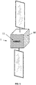
Figure 1 schematically represents a spacecraft including a marking on a surface on an outer cover material thereof. -
Figure 2a shows an example of marking obtained on a surface made of StaMet-coated black Kapton, -
Figure 2b shows an example of marking obtained on a surface made of black Kapton. - A method of manufacturing a spacecraft will now be described. The
spacecraft 1 may be a satellite, a space probe, a space vehicle or a space station. In what follows, the word "space" designates the part of the universe that is located outside from any spacecraft. - The method comprises selecting an
outer cover material 10 for the spacecraft, having an inner surface and an outer surface. By "outer surface" it is meant the surface of the cover material that is exposed to space when the cover material is assembled to the spacecraft, whereas the "inner surface" corresponds to the surface that is facing the structure of the spacecraft that is covered by the outer cover material, when the latter is assembled to the spacecraft. - As the outer surface of the outer cover material may be exposed to ionizing radiations, said surface is electrically conductive in order to prevent electrical charges from accumulating and to form potential differences that can lead to formation of electrical arcing that could damage the spacecraft. The outer surface of the outer cover material is thus equipotential, i.e. it exhibits the same electrical potential on its entire surface.
- The
outer cover material 10 may also be thermally insulating. In embodiments, the outer cover material may be a multilayer insulation blanket, which may comprise a plurality of stacked thermally insulating layers, and an external layer that has an outer surface which is electrically conductive. - The method further comprises exposing the outer surface of the outer cover material to laser source, in order to achieve a marking 11 on said outer surface.
- The marking 11 may comprise characters, numbers, symbols or logos. The content of the marking may be technical, informational or commercial.
- When the
marking 11 is performed on the outer surface of the outer cover material, said marking can thus be visible from the outside of the spacecraft, either during manufacturing of the spacecraft or during its operation. - The surface that is exposed to laser source in order to be marked is preferably formed of a material elected within a group consisting in:
- polyimide (or trade name Kapton),
- black polyimide (or black Kapton), which is loaded with conductive carbon in order to be electrically conductive,
- germanium-coated polyimide,
- germanium-coated black polyimide,
- StaMet-coated polyimide, StaMet-coated black polyimide,
- Where StaMet corresponds to a silicon aluminum alloy.
- For instance, the outer cover material may comprise a plurality of thermally insulating layers made of polyimide (or trade name Kapton). An external layer of the outer cover material may also be made of polyimide, or, in order to have an outer surface electrically conductive, may be formed of black polyimide or any of the previously-mentioned coated polyimide materials.
- It has been found out by the inventors that no preliminary treatment of the surface exposed to laser source is required, nor any change in the composition of the cover material. No additive, in particular no addition of any photosensitive material is required in order to allow achieving visible marking of the exposed surface. The absence of paint also removes any risk of degradation of the paint under the conditions present in space (vacuum, thermal aging, exposure to UV radiations), and pollution of the nearby equipment or instrument.
- Furthermore, such materials may be laser-marked while maintaining an electrical outer surface conductivity and with a limited impact on thermal performances of the outer cover material, and without producing contamination particles. In particular, the laser-marking is performed such that the emissivity of the material forming the exposed surface varies of less than 10% between marked areas and unmarked areas.
- To this end, the laser may be a pulsed laser operating in the UV range, and more specifically in a range of 350 - 370 nm, for instance equal to 355 nm.
- The pulses of the laser may be set to last between 10 and 100 ns, the pulses being emitted at a frequency comprised between 1 and 50 kHz and preferably 40kHz.The repetitions of impulses are comprised between 1 and 25. The number of repetitions corresponds to the number of repetitions of the same parameter set which is applied to the substrate in order to improve the visibility. The focus is set at the focal point. The average power of the laser may be comprised between 0.5 and 2,6 W.
- The marking may be performed by moving the laser relatively to the exposed surface with a lateral speed comprised between 500 and 1500 mm/s, for instance equal to 1000 mm/s.
- The area covered by the marking can be greater than 10 cm2, preferably greater than 100 cm2, for instance comprised between 100 cm2 and 1 m2, depending on the laser source capacity. The process is not restricted to a maximum size, but the marking area is linked to the geometric limitations of the facility.
- The outer cover material is used for covering at least part of the structure of the spacecraft during its manufacturing. The marking of a surface of said outer cover material may be performed prior to covering the structure of the spacecraft with said material. Alternatively, the marking of the surface may be performed once the cover material is assembled onto the spacecraft.
- With reference to
figures 2a and 2b are shown exemplary markings obtained respectively on StaMet-coated black Kapton and black Kapton, with the laser parameters indicated above. - The emissivity ε and absorptance α of the surface exposed to the laser source were measured before and after exposition to the laser and are provided in the tables below.
- The emissivity of the surface of a material is its effectiveness in emitting energy as thermal radiation. It is the ratio of the thermal radiation from a surface to the radiation from an ideal black surface at the same temperature.
- The absorptance of the surface of a material is its effectiveness in absorbing radiant energy. It is the ratio of the absorbed to the incident radiant power.
StaMet-coated black Kapton foil Unmarked Laser marked ε 20° 0.875 0.868 ε 80° 0.807 0.802 ε 180° 0.777 0.772 α 0.494 0.950 Black Kapton foil Unmarked Laser marked ε 20° 0.880 0.914 ε 80° 0.809 0.869 ε 180° 0.780 0.803 α 0.933 0.963 - As can be seen on
figure 2a , Stamet-coated black Kapton has a relatively light color and the marking results in darker areas, hence an important increase of absorptance. By contrast, black Kapton is a darker material and, while the marking remains visible, the contrast between marked areas and unmarked areas is not as pronounced, and the increase in absorptance is also reduced (3%). - Hence, one can select the outer cover material, and in particular the material forming the surface to be marked, according to its requirements in terms of absorptance.
- The surface conductivity of the material was also measured before and after exposition to the laser, and no change was observed.
- Last, no detachment of particles was observed after cleaning the exposed surface with a piece of tissue impregnated with isopropyl alcohol.
Claims (11)
- A method of manufacturing a spacecraft comprising selecting an outer cover material for the spacecraft, the outer cover material having an inner surface and an outer surface, said outer surface being electrically conductive, wherein the method further comprises partially exposing the outer surface of the outer cover material to laser source to achieve a marking on said outer surface.
- The method according to claim 1 or 2, wherein the outer cover material is a multilayer insulation blanket.
- The method according to any of the preceding claims, wherein the exposing the outer surface to laser source is performed such that the emissivity of the material forming the exposed surface varies of less than 10% between marked areas and unmarked areas.
- The method according to any of the preceding claims, wherein the outer surface exposed to laser source is formed of a material elected within the group consisting in polyimide, black polyimide, germanium-coated polyimide, germanium-coated black polyimide, StaMet-coated polyimide and StaMet-coated black polyimide.
- The method according to any of the preceding claims, wherein the outer surface exposed to laser source is devoid of photosensitive material.
- The method according to any of the preceding claims, wherein the laser is a UV laser, in the wavelength range of 350 - 370 nm, preferably of 355 nm.
- The method according to any of the preceding claims, comprising performing the marking by moving the laser relatively to the exposed surface with a lateral speed comprised between 500 and 1500 mm/s, preferably a lateral speed of 1000 mm/s.
- The method according to any of the preceding claims, wherein the laser exhibits an average power comprised between 0.5 and 2.6 W.
- The method according to any of the preceding claims, wherein the laser is a pulsed laser operating at a frequency comprised between 1 and 50 kHz and with a pulse duration comprised between 10 and 100 nsec.
- A spacecraft (1) comprising an outer cover material (10) exhibiting at least one marking (11) on its outer surface, the spacecraft being characterized in that it is manufactured according to the method of any of the preceding claims.
- A spacecraft (1) according to claim 10, wherein the outer cover material (10) is a multilayer insulation blanket.
Priority Applications (4)
| Application Number | Priority Date | Filing Date | Title |
|---|---|---|---|
| EP21306028.8A EP4122832A1 (en) | 2021-07-22 | 2021-07-22 | Manufacturing method of a spacecraft including a marking of a surface |
| US18/290,583 US12338005B2 (en) | 2021-07-22 | 2022-03-14 | Manufacturing method of a spacecraft including a marking of a surface |
| PCT/EP2022/056576 WO2023001414A1 (en) | 2021-07-22 | 2022-03-14 | Manufacturing method of a spacecraft including a marking of a surface |
| EP22710636.6A EP4146545B1 (en) | 2021-07-22 | 2022-03-14 | Manufacturing method of a spacecraft including a marking of a surface |
Applications Claiming Priority (1)
| Application Number | Priority Date | Filing Date | Title |
|---|---|---|---|
| EP21306028.8A EP4122832A1 (en) | 2021-07-22 | 2021-07-22 | Manufacturing method of a spacecraft including a marking of a surface |
Publications (1)
| Publication Number | Publication Date |
|---|---|
| EP4122832A1 true EP4122832A1 (en) | 2023-01-25 |
Family
ID=77564039
Family Applications (2)
| Application Number | Title | Priority Date | Filing Date |
|---|---|---|---|
| EP21306028.8A Withdrawn EP4122832A1 (en) | 2021-07-22 | 2021-07-22 | Manufacturing method of a spacecraft including a marking of a surface |
| EP22710636.6A Active EP4146545B1 (en) | 2021-07-22 | 2022-03-14 | Manufacturing method of a spacecraft including a marking of a surface |
Family Applications After (1)
| Application Number | Title | Priority Date | Filing Date |
|---|---|---|---|
| EP22710636.6A Active EP4146545B1 (en) | 2021-07-22 | 2022-03-14 | Manufacturing method of a spacecraft including a marking of a surface |
Country Status (3)
| Country | Link |
|---|---|
| US (1) | US12338005B2 (en) |
| EP (2) | EP4122832A1 (en) |
| WO (1) | WO2023001414A1 (en) |
Citations (4)
| Publication number | Priority date | Publication date | Assignee | Title |
|---|---|---|---|---|
| US7163179B1 (en) * | 2003-02-14 | 2007-01-16 | Taylor Thomas C | Commercial service platform in space |
| US7252890B1 (en) * | 2004-03-01 | 2007-08-07 | Lockheed Martin Corporation | Anti-contamination coated multi-layer insulation |
| JP2012024818A (en) * | 2010-07-26 | 2012-02-09 | Mitsubishi Electric Corp | Multi-layer heat insulation material, and method for embossing thin titanium sheet material |
| US20210065594A1 (en) * | 2019-08-30 | 2021-03-04 | The Boeing Company | Exterior Lighting in Aircraft Livery |
Family Cites Families (6)
| Publication number | Priority date | Publication date | Assignee | Title |
|---|---|---|---|---|
| GB2215116B (en) | 1988-02-05 | 1992-07-29 | British Aerospace | A method of marking a cable or tube with a laser. |
| DE19531490A1 (en) * | 1995-08-26 | 1997-02-27 | Basf Ag | Process for labeling molded articles |
| FR2842532B1 (en) | 2002-07-22 | 2007-05-25 | Plastic Omnium Cie | FLUORINE POLYMER-BASED MATERIAL, LASER MARKING |
| US9168696B2 (en) * | 2012-06-04 | 2015-10-27 | Sabic Global Technologies B.V. | Marked thermoplastic compositions, methods of making and articles comprising the same, and uses thereof |
| DE102011121546B4 (en) | 2011-12-20 | 2013-07-11 | Eads Deutschland Gmbh | Method for structuring a surface of a workpiece |
| US20150048209A1 (en) * | 2013-08-16 | 2015-02-19 | Robert Hoyt | Structures with Internal Microstructures to Provide Multifunctional Capabilities |
-
2021
- 2021-07-22 EP EP21306028.8A patent/EP4122832A1/en not_active Withdrawn
-
2022
- 2022-03-14 US US18/290,583 patent/US12338005B2/en active Active
- 2022-03-14 EP EP22710636.6A patent/EP4146545B1/en active Active
- 2022-03-14 WO PCT/EP2022/056576 patent/WO2023001414A1/en not_active Ceased
Patent Citations (4)
| Publication number | Priority date | Publication date | Assignee | Title |
|---|---|---|---|---|
| US7163179B1 (en) * | 2003-02-14 | 2007-01-16 | Taylor Thomas C | Commercial service platform in space |
| US7252890B1 (en) * | 2004-03-01 | 2007-08-07 | Lockheed Martin Corporation | Anti-contamination coated multi-layer insulation |
| JP2012024818A (en) * | 2010-07-26 | 2012-02-09 | Mitsubishi Electric Corp | Multi-layer heat insulation material, and method for embossing thin titanium sheet material |
| US20210065594A1 (en) * | 2019-08-30 | 2021-03-04 | The Boeing Company | Exterior Lighting in Aircraft Livery |
Also Published As
| Publication number | Publication date |
|---|---|
| EP4146545B1 (en) | 2023-09-13 |
| EP4146545C0 (en) | 2023-09-13 |
| US12338005B2 (en) | 2025-06-24 |
| WO2023001414A1 (en) | 2023-01-26 |
| EP4146545A1 (en) | 2023-03-15 |
| US20240253823A1 (en) | 2024-08-01 |
Similar Documents
| Publication | Publication Date | Title |
|---|---|---|
| EP0914260B1 (en) | Process for preparing high resolution emissive arrays and corresponding articles | |
| TWI580059B (en) | Method of manufacturing an electrode for a solar cell | |
| JP5474865B2 (en) | Glass frit, composition for forming sealing material, and light emitting device | |
| JP2007200838A (en) | Organic electroluminescent display device and manufacturing method thereof | |
| US7476629B2 (en) | Beam irradiation apparatus, beam irradiation method, and method for manufacturing thin film transistor | |
| EP0806055A1 (en) | Manufacture of electric devices comprising thin-film circuitry on an organic substrate | |
| TW200807563A (en) | Method of heat treatment for semiconductor | |
| US4443493A (en) | Laser induced flow glass materials | |
| US10199521B2 (en) | Thick damage buffer for foil-based metallization of solar cells | |
| KR20050052303A (en) | Thermal transfer element with lthc having gradient concentration | |
| EP4146545B1 (en) | Manufacturing method of a spacecraft including a marking of a surface | |
| KR100700654B1 (en) | Laser Irradiation Device and Laser Thermal Transfer Method | |
| US4431900A (en) | Laser induced flow Ge-O based materials | |
| WO1997024768A1 (en) | Improved laser grooving and doping method | |
| KR102940036B1 (en) | Manufacturing method of current collector and current collector manucatured thereby | |
| KR20060008524A (en) | Crystallization Method Of Amorphous Silicon Layer | |
| KR20070024285A (en) | Laser thermoelectric donor film, organic light emitting display device and manufacturing method using same | |
| JP2587971B2 (en) | Thin film formation method | |
| JPH0645483B2 (en) | Substrate for liquid crystal display device and manufacturing method thereof | |
| RU2525147C2 (en) | Method of producing patterned organic light-emitting diode | |
| DE102015114240B4 (en) | Device and method for processing a semiconductor substrate using laser radiation | |
| KR102000044B1 (en) | Laser induced thermal imaging film and method of manufacturing organic light emitting diode display device using the same | |
| JP2002075190A (en) | Film forming method and image display device incorporating spacer formed using the same |
Legal Events
| Date | Code | Title | Description |
|---|---|---|---|
| PUAI | Public reference made under article 153(3) epc to a published international application that has entered the european phase |
Free format text: ORIGINAL CODE: 0009012 |
|
| STAA | Information on the status of an ep patent application or granted ep patent |
Free format text: STATUS: THE APPLICATION HAS BEEN PUBLISHED |
|
| AK | Designated contracting states |
Kind code of ref document: A1 Designated state(s): AL AT BE BG CH CY CZ DE DK EE ES FI FR GB GR HR HU IE IS IT LI LT LU LV MC MK MT NL NO PL PT RO RS SE SI SK SM TR |
|
| STAA | Information on the status of an ep patent application or granted ep patent |
Free format text: STATUS: THE APPLICATION IS DEEMED TO BE WITHDRAWN |
|
| 18D | Application deemed to be withdrawn |
Effective date: 20230726 |