EP4122735B1 - Telehandler with convertible propulsion - Google Patents
Telehandler with convertible propulsion Download PDFInfo
- Publication number
- EP4122735B1 EP4122735B1 EP22181031.0A EP22181031A EP4122735B1 EP 4122735 B1 EP4122735 B1 EP 4122735B1 EP 22181031 A EP22181031 A EP 22181031A EP 4122735 B1 EP4122735 B1 EP 4122735B1
- Authority
- EP
- European Patent Office
- Prior art keywords
- telehandler
- electricity generator
- generator apparatus
- compartment
- battery
- Prior art date
- Legal status (The legal status is an assumption and is not a legal conclusion. Google has not performed a legal analysis and makes no representation as to the accuracy of the status listed.)
- Active
Links
Images


Classifications
-
- B—PERFORMING OPERATIONS; TRANSPORTING
- B60—VEHICLES IN GENERAL
- B60K—ARRANGEMENT OR MOUNTING OF PROPULSION UNITS OR OF TRANSMISSIONS IN VEHICLES; ARRANGEMENT OR MOUNTING OF PLURAL DIVERSE PRIME-MOVERS IN VEHICLES; AUXILIARY DRIVES FOR VEHICLES; INSTRUMENTATION OR DASHBOARDS FOR VEHICLES; ARRANGEMENTS IN CONNECTION WITH COOLING, AIR INTAKE, GAS EXHAUST OR FUEL SUPPLY OF PROPULSION UNITS IN VEHICLES
- B60K6/00—Arrangement or mounting of plural diverse prime-movers for mutual or common propulsion, e.g. hybrid propulsion systems comprising electric motors and internal combustion engines
- B60K6/20—Arrangement or mounting of plural diverse prime-movers for mutual or common propulsion, e.g. hybrid propulsion systems comprising electric motors and internal combustion engines the prime-movers consisting of electric motors and internal combustion engines, e.g. HEVs
- B60K6/22—Arrangement or mounting of plural diverse prime-movers for mutual or common propulsion, e.g. hybrid propulsion systems comprising electric motors and internal combustion engines the prime-movers consisting of electric motors and internal combustion engines, e.g. HEVs characterised by apparatus, components or means specially adapted for HEVs
-
- B—PERFORMING OPERATIONS; TRANSPORTING
- B60—VEHICLES IN GENERAL
- B60K—ARRANGEMENT OR MOUNTING OF PROPULSION UNITS OR OF TRANSMISSIONS IN VEHICLES; ARRANGEMENT OR MOUNTING OF PLURAL DIVERSE PRIME-MOVERS IN VEHICLES; AUXILIARY DRIVES FOR VEHICLES; INSTRUMENTATION OR DASHBOARDS FOR VEHICLES; ARRANGEMENTS IN CONNECTION WITH COOLING, AIR INTAKE, GAS EXHAUST OR FUEL SUPPLY OF PROPULSION UNITS IN VEHICLES
- B60K6/00—Arrangement or mounting of plural diverse prime-movers for mutual or common propulsion, e.g. hybrid propulsion systems comprising electric motors and internal combustion engines
- B60K6/20—Arrangement or mounting of plural diverse prime-movers for mutual or common propulsion, e.g. hybrid propulsion systems comprising electric motors and internal combustion engines the prime-movers consisting of electric motors and internal combustion engines, e.g. HEVs
- B60K6/42—Arrangement or mounting of plural diverse prime-movers for mutual or common propulsion, e.g. hybrid propulsion systems comprising electric motors and internal combustion engines the prime-movers consisting of electric motors and internal combustion engines, e.g. HEVs characterised by the architecture of the hybrid electric vehicle
- B60K6/46—Series type
-
- B—PERFORMING OPERATIONS; TRANSPORTING
- B60—VEHICLES IN GENERAL
- B60L—PROPULSION OF ELECTRICALLY-PROPELLED VEHICLES; SUPPLYING ELECTRIC POWER FOR AUXILIARY EQUIPMENT OF ELECTRICALLY-PROPELLED VEHICLES; ELECTRODYNAMIC BRAKE SYSTEMS FOR VEHICLES IN GENERAL; MAGNETIC SUSPENSION OR LEVITATION FOR VEHICLES; MONITORING OPERATING VARIABLES OF ELECTRICALLY-PROPELLED VEHICLES; ELECTRIC SAFETY DEVICES FOR ELECTRICALLY-PROPELLED VEHICLES
- B60L50/00—Electric propulsion with power supplied within the vehicle
- B60L50/10—Electric propulsion with power supplied within the vehicle using propulsion power supplied by engine-driven generators, e.g. generators driven by combustion engines
-
- B—PERFORMING OPERATIONS; TRANSPORTING
- B60—VEHICLES IN GENERAL
- B60L—PROPULSION OF ELECTRICALLY-PROPELLED VEHICLES; SUPPLYING ELECTRIC POWER FOR AUXILIARY EQUIPMENT OF ELECTRICALLY-PROPELLED VEHICLES; ELECTRODYNAMIC BRAKE SYSTEMS FOR VEHICLES IN GENERAL; MAGNETIC SUSPENSION OR LEVITATION FOR VEHICLES; MONITORING OPERATING VARIABLES OF ELECTRICALLY-PROPELLED VEHICLES; ELECTRIC SAFETY DEVICES FOR ELECTRICALLY-PROPELLED VEHICLES
- B60L53/00—Methods of charging batteries, specially adapted for electric vehicles; Charging stations or on-board charging equipment therefor; Exchange of energy storage elements in electric vehicles
- B60L53/50—Charging stations characterised by energy-storage or power-generation means
- B60L53/54—Fuel cells
-
- B—PERFORMING OPERATIONS; TRANSPORTING
- B66—HOISTING; LIFTING; HAULING
- B66F—HOISTING, LIFTING, HAULING OR PUSHING, NOT OTHERWISE PROVIDED FOR, e.g. DEVICES WHICH APPLY A LIFTING OR PUSHING FORCE DIRECTLY TO THE SURFACE OF A LOAD
- B66F9/00—Devices for lifting or lowering bulky or heavy goods for loading or unloading purposes
- B66F9/06—Devices for lifting or lowering bulky or heavy goods for loading or unloading purposes movable, with their loads, on wheels or the like, e.g. fork-lift trucks
- B66F9/065—Devices for lifting or lowering bulky or heavy goods for loading or unloading purposes movable, with their loads, on wheels or the like, e.g. fork-lift trucks non-masted
- B66F9/0655—Devices for lifting or lowering bulky or heavy goods for loading or unloading purposes movable, with their loads, on wheels or the like, e.g. fork-lift trucks non-masted with a telescopic boom
-
- B—PERFORMING OPERATIONS; TRANSPORTING
- B66—HOISTING; LIFTING; HAULING
- B66F—HOISTING, LIFTING, HAULING OR PUSHING, NOT OTHERWISE PROVIDED FOR, e.g. DEVICES WHICH APPLY A LIFTING OR PUSHING FORCE DIRECTLY TO THE SURFACE OF A LOAD
- B66F9/00—Devices for lifting or lowering bulky or heavy goods for loading or unloading purposes
- B66F9/06—Devices for lifting or lowering bulky or heavy goods for loading or unloading purposes movable, with their loads, on wheels or the like, e.g. fork-lift trucks
- B66F9/075—Constructional features or details
- B66F9/07513—Details concerning the chassis
- B66F9/07527—Covers for, e.g. engines or batteries
-
- B—PERFORMING OPERATIONS; TRANSPORTING
- B66—HOISTING; LIFTING; HAULING
- B66F—HOISTING, LIFTING, HAULING OR PUSHING, NOT OTHERWISE PROVIDED FOR, e.g. DEVICES WHICH APPLY A LIFTING OR PUSHING FORCE DIRECTLY TO THE SURFACE OF A LOAD
- B66F9/00—Devices for lifting or lowering bulky or heavy goods for loading or unloading purposes
- B66F9/06—Devices for lifting or lowering bulky or heavy goods for loading or unloading purposes movable, with their loads, on wheels or the like, e.g. fork-lift trucks
- B66F9/075—Constructional features or details
- B66F9/07513—Details concerning the chassis
- B66F9/07531—Battery compartments
-
- B—PERFORMING OPERATIONS; TRANSPORTING
- B66—HOISTING; LIFTING; HAULING
- B66F—HOISTING, LIFTING, HAULING OR PUSHING, NOT OTHERWISE PROVIDED FOR, e.g. DEVICES WHICH APPLY A LIFTING OR PUSHING FORCE DIRECTLY TO THE SURFACE OF A LOAD
- B66F9/00—Devices for lifting or lowering bulky or heavy goods for loading or unloading purposes
- B66F9/06—Devices for lifting or lowering bulky or heavy goods for loading or unloading purposes movable, with their loads, on wheels or the like, e.g. fork-lift trucks
- B66F9/075—Constructional features or details
- B66F9/07513—Details concerning the chassis
- B66F9/0754—Battery removal arrangements
-
- B—PERFORMING OPERATIONS; TRANSPORTING
- B66—HOISTING; LIFTING; HAULING
- B66F—HOISTING, LIFTING, HAULING OR PUSHING, NOT OTHERWISE PROVIDED FOR, e.g. DEVICES WHICH APPLY A LIFTING OR PUSHING FORCE DIRECTLY TO THE SURFACE OF A LOAD
- B66F9/00—Devices for lifting or lowering bulky or heavy goods for loading or unloading purposes
- B66F9/06—Devices for lifting or lowering bulky or heavy goods for loading or unloading purposes movable, with their loads, on wheels or the like, e.g. fork-lift trucks
- B66F9/075—Constructional features or details
- B66F9/07572—Propulsion arrangements
-
- B—PERFORMING OPERATIONS; TRANSPORTING
- B66—HOISTING; LIFTING; HAULING
- B66F—HOISTING, LIFTING, HAULING OR PUSHING, NOT OTHERWISE PROVIDED FOR, e.g. DEVICES WHICH APPLY A LIFTING OR PUSHING FORCE DIRECTLY TO THE SURFACE OF A LOAD
- B66F9/00—Devices for lifting or lowering bulky or heavy goods for loading or unloading purposes
- B66F9/06—Devices for lifting or lowering bulky or heavy goods for loading or unloading purposes movable, with their loads, on wheels or the like, e.g. fork-lift trucks
- B66F9/075—Constructional features or details
- B66F9/20—Means for actuating or controlling masts, platforms, or forks
- B66F9/24—Electrical devices or systems
-
- B—PERFORMING OPERATIONS; TRANSPORTING
- B60—VEHICLES IN GENERAL
- B60L—PROPULSION OF ELECTRICALLY-PROPELLED VEHICLES; SUPPLYING ELECTRIC POWER FOR AUXILIARY EQUIPMENT OF ELECTRICALLY-PROPELLED VEHICLES; ELECTRODYNAMIC BRAKE SYSTEMS FOR VEHICLES IN GENERAL; MAGNETIC SUSPENSION OR LEVITATION FOR VEHICLES; MONITORING OPERATING VARIABLES OF ELECTRICALLY-PROPELLED VEHICLES; ELECTRIC SAFETY DEVICES FOR ELECTRICALLY-PROPELLED VEHICLES
- B60L2200/00—Type of vehicles
- B60L2200/40—Working vehicles
- B60L2200/42—Fork lift trucks
-
- B—PERFORMING OPERATIONS; TRANSPORTING
- B60—VEHICLES IN GENERAL
- B60W—CONJOINT CONTROL OF VEHICLE SUB-UNITS OF DIFFERENT TYPE OR DIFFERENT FUNCTION; CONTROL SYSTEMS SPECIALLY ADAPTED FOR HYBRID VEHICLES; ROAD VEHICLE DRIVE CONTROL SYSTEMS FOR PURPOSES NOT RELATED TO THE CONTROL OF A PARTICULAR SUB-UNIT
- B60W2300/00—Indexing codes relating to the type of vehicle
- B60W2300/12—Trucks; Load vehicles
Definitions
- This invention relates to a telehandler with convertible propulsion.
- the invention relates to a telehandler with a propulsion that can be switched from electric to hybrid and vice versa by the user.
- the use of the telehandler is requested in more than one work site or that, at the end of the planned operations, the vehicle must be returned to the yard; in these circumstances, the residual autonomy of the batteries may not be sufficient to move the telehandler to the destination, which requires inconvenient and time-consuming procedures for recharging the batteries.
- DE 44 27 322 discloses an electricity generator unit that has three uses: it can be inserted in (and then extracted from) an electric car, in order to temporarily convert it into a hybrid vehicle; it can be used for home heating; and It can be used as a kind of generator set for home utilities.
- EP3112312A1 discloses a hybrid telehandler.
- the technical purpose which forms the basis of the invention is to provide a telehandler with switchable power supply which overcomes the limitations of the prior art.
- the numeral 1 denotes in its entirety an electrically powered telehandler according to the invention.
- the telehandler 1 proposed is equipped with a frame 11, or "carriage”, movable on wheels and may be either fixed or rotary, that is to say, it can mount the cab and the operating arm directly on the carriage 11 or, as in the case illustrated, may be equipped with a platform, or “turret” 110, mounted rotatably on the carriage 11, which supports the cab and operating arm.
- the telehandler 1 may comprise at least one electric drive motor positioned at one of the axles and an electric motor for driving the hydraulic pump which powers, using a distributor, the movement cylinders of the arm 111 and, if necessary, the motor-driven rack of the tower 110.
- the telehandler 1 is advantageously equipped with a plurality of containment compartments 100 for housing the means 200, 300 which power at least the propulsion motor.
- the power supply means comprise the energy sources 200, 300 which, considered as a whole, electrically power at least the propulsion motor and the pump motor.
- the carriage 11 of the telehandler can define two lateral compartments 100, made in its opposite lateral portions, right and left, accessible on opposite sides, each of which is designed to house the above-mentioned power supply means 200, 300.
- At least one of the compartments 100 (and preferably all) is provided with an access opening to allow a user to insert or extract, and in particular replace, the power supply means 200, 300.
- the access opening of the compartment 100 may be positioned on a relative side of the carriage 11, facing outwards, thereby allowing an insertion and an extraction of the power supply means 200, 300 along a horizontal direction (see Figures 2 - 6 ).
- the opening is equipped with a door 101, or "hood”, to allow access to the compartment 100 from the outside; the door 101 may be of the tilting type and equipped with a lock.
- the invention also comprises two types of electricity supply sources: electric batteries 200 and electricity generator apparatuses 300.
- the invention uses a plurality of electric batteries 200, each designed to be inserted in one of the compartments 100 and at least one electricity generator apparatus 300 designed to be inserted in one of the compartments 100.
- the electricity generator apparatus 300 may be designed for producing electricity by consuming fossil fuel, for example it may be a so-called “diesel-electric generator” or it may be a fuel cell or other apparatus which, starting from some form of fuel, produces electricity.
- the telehandler 1 is provided with two alternative power supply configurations, which can be switched by the action of a user:
- the power supply means which are on board the telehandler 1 include batteries 200 but not electricity generator apparatuses 300, whilst in the hybrid configuration they include at least one electricity generator apparatus 300.
- the power supply means include an electric battery 200 which supplies the propulsion motor and the motor which drives the pump and an electricity generator apparatus 300 set up for charging the battery 200.
- an electricity generator apparatus 300 set up for charging the battery 200.
- the proposed telehandler 1 can work, when it is in its fully electrical configuration, without restrictions in town centres or in closed environments, powered by its batteries 200 contained in the lateral compartments 100 of the carriage 11.
- the operator When the work is finished, or in any case when it is necessary for the telehandler 1 to be moved to another site which is not close by, the operator will open one of the compartments and will extract the respective battery 200 (see the sequence of Figures 2 , 3 and 4 ), unless the machine 1 is working with a single battery 200, in which case the hood 101 of the empty compartment will be opened.
- the generator 300 will be inserted in the compartment 100 (see Figures 5 and 6 ) and will be connected to the electrical system inside the telehandler 1, which is now in its hybrid configuration, in such a way that the generator 300 charges the battery 200 contained in the other compartment 100. After that, having obtained the necessary autonomy, the telehandler 1 can be driven to the destination.
- the proposed telehandler 1 can be switched from the hybrid configuration to the fully electrical configuration and vice versa allows customers to have a versatile machine 1 which can work in environments with emission restrictions, but has the autonomy of a traditional hybrid machine or also of a traditional diesel machine; for this reason, customers can make savings by not having to purchase a plurality of telehandlers having different power supply systems.
- the telehandler 1 can continue the programmed operations using the energy stored in the other battery 200. After that, with the first battery 200 recharged, it will be again transported to the work site in order, for example, to replace the other battery 200, which in the meantime has drained and so on.
- the telehandler 1 may also use only one battery 200, if the activity for which it is used can be carried out before it drains or also use the current of both the batteries 200 simultaneously, as described in more detail below.
- the telehandler 1 is equipped with a single compartment 100, it is still possible to use two batteries 200, so that once the battery housed in the compartment 100 has been discharged, the other one is already available near by, to enable replacement.
- the batteries 200 and the electricity generator apparatuses 300 which can be replaced according to the invention are equipped, at the lower side, with insertion seats 201, 301 for receiving the prongs of a loading fork, to allow the movement by means of a forklift truck.
- the battery 200 and the electricity generator apparatus 300 may have a bottom which defines or consists of or is fixed to a base shaped like a pallet, for the purpose of inserting forks and the movement with a customary forklift truck.
- the replacement occurs by opening the door 101, placing forks beneath the battery 200 or the electricity generator apparatus 300, after electrical disconnection and extracting it from the compartment 100 making it slide on the guide means 103, 104; subsequently, after placing forks beneath another battery 200 or another electricity generator apparatus, moving it to the height of the opening and then inserting it by sliding on the guide means 103, 104, examples of which are described in more detail below.
- the battery 200 comprises a connector 202 for dispensing the current (possibly only one), which can be connected to a respective single transmission cable 105 (possibly only one) positioned in the compartment 100, connected to the electrical system of the telehandler 1 and connected to the above-mentioned electric motors, for the purposes of their power supply.
- the accompanying drawings also show the optional solution is shown of providing an internal connector 102 to the compartment to which the cable 105 is attached when the door 101 is closed with an empty compartment 100; in this way, the telehandler 1 can be started, using the other battery 200 without an open circuit remaining in the system.
- the battery 200 may be equipped with an ON/OFF switch 203 (indicated in Figure 7 ) which is used to disconnect it electrically, without the need to disconnect the cable 105, to prevent it from being drained during non-operating periods when it remains on board the telehandler 1.
- an ON/OFF switch 203 (indicated in Figure 7 ) which is used to disconnect it electrically, without the need to disconnect the cable 105, to prevent it from being drained during non-operating periods when it remains on board the telehandler 1.
- the invention provides optionally the use of an electricity generator apparatus consisting of a diesel-electric generator 300 with a new design, specifically conceived to be used in the hybrid configuration of the proposed telehandler.
- the apparatus 300 includes a casing 302 which firstly contains an internal combustion engine 303, equipped with one or more exhaust pipes 304, facing downwards for emitting the exhaust gases outside the casing 302, a radiator 305 and a tank for the water 306.
- the tank 307 for the diesel oil which supplies the internal combustion engine 303 may also be positioned in such a way as to form one of the walls of the casing 302 which contains the above-mentioned components.
- the casing 302 also contains the actual generator 308, that is to say, the alternator which, driven by the internal combustion engine 303, produces the current with which the battery 200 of the telehandler 1 is charged, in its hybrid configuration.
- the inverter 309 used to control this current may also be mounted on the outer surface of the casing 302, for example above the above-mentioned tank 307 and is connected to the generator 308 by suitable wiring 310.
- the casing 302 also mounts, externally, a connector 311 like that of the battery 200, designed to be connected to the above-mentioned transmission cable 105.
- the electrical system which connects the battery 200 to the motors and the electricity generator apparatus 300 to the battery 200 includes all the usual electrical and electronic devices for the operation of motors and other user devices, such as inverters positioned upstream of the motors, units for distributing the power supply downstream of the batteries 200 (typically one for each battery), chargers for charging the batteries 200 by means of an external socket (to be used if there is a power supply source close to the work site, for example a column for recharging the batteries) and the various circuits for the lighting of the flashing warning lights and reflectors, internal lighting, etc.
- inverters positioned upstream of the motors
- units for distributing the power supply downstream of the batteries 200 typically one for each battery
- chargers for charging the batteries 200 by means of an external socket to be used if there is a power supply source close to the work site, for example a column for recharging the batteries
- the above-mentioned guide means 103, 104 include a lower shaped surface 103 of the compartment 100, which is equipped with recesses for slidably receiving the seats 201 for inserting the prongs which are located at the lower surface of the energy source 200, 300 housed in the compartment 100.
- the battery 200 and the electricity generator apparatus 300 may be equipped with respective engagement elements 204, for example in the form of wings protruding from respective opposite sides; it should be noted that, although the drawing only shows the case of the battery 200, the engagement elements 204 might also be mounted on the electricity generator apparatus 300.
- the wings 204 which protrude from opposite lateral surfaces of the energy source 200, 300 allow a slidable engagement with respective lateral guide elements 104 (see Figure 8 ), made, for example, by metal plates, which are positioned in the compartment 100, to define shelves 104 on which the wings 204 of the battery 200 or of the apparatus 300, which are therefore supported by them, slide into place.
- releasable locking means 106 consisting, for example, of screws and/or bolts, may be provided to prevent the involuntary extraction of the battery 200 from the inside of the compartment 100.
- tilting retaining panel 107 hinged at the lower edge of the opening and which can be lowered upon completion of the extraction and insertion of the battery 200 or of the electricity generator apparatus.
- the invention may include electronic processing means, connectable to the battery 200 or to the batteries 200 contained/and in the compartment 100 and designed to adjust the supply of current.
- the processing means which may also consist of or included in or connected to the control unit usually used in telehandlers 1, include a current regulating module configured in such a way as to adjust the supply of current of the various batteries 200 according to variable proportions.
- the operator in the cab can establish, by means of a user interface connected to the processing means, how much current is to be picked up from one of the batteries 200 relative to the other in order to supply the user devices of the vehicle; in particular cases, only one battery 200 supplies the electric motors of the telehandler 1 or both the batteries 200 dispense half of the electricity requested.
- the processing means may include a control module of the electricity generator apparatus 300, configured for adjusting its operation; again thanks to the above-mentioned interface, the operator can manage or set up the operation of the electricity generator apparatus 300 and the battery 200.
Landscapes
- Engineering & Computer Science (AREA)
- Transportation (AREA)
- Structural Engineering (AREA)
- Mechanical Engineering (AREA)
- Life Sciences & Earth Sciences (AREA)
- Civil Engineering (AREA)
- Geology (AREA)
- Combustion & Propulsion (AREA)
- Chemical & Material Sciences (AREA)
- Power Engineering (AREA)
- Sustainable Development (AREA)
- Sustainable Energy (AREA)
- Arrangement Or Mounting Of Propulsion Units For Vehicles (AREA)
- Charge And Discharge Circuits For Batteries Or The Like (AREA)
- Forklifts And Lifting Vehicles (AREA)
- Manipulator (AREA)
- Battery Mounting, Suspending (AREA)
- Infusion, Injection, And Reservoir Apparatuses (AREA)
- Electric Propulsion And Braking For Vehicles (AREA)
Description
- This invention relates to a telehandler with convertible propulsion.
- In detail, the invention relates to a telehandler with a propulsion that can be switched from electric to hybrid and vice versa by the user.
- There are prior art electric telehandlers, equipped with an electric motor, powered by one or more batteries, in place of the traditional internal combustion engine, which have the advantage of not diffusing exhaust gas in the environments in which they work.
- The environmental regulations of many countries require that electric telehandlers be used instead of those with a fossil fuel power supply if works are to be performed in closed environments, such as industrial sheds, or in zones of residential centres where restrictions apply to the traffic and to the type of vehicles allowed to circulate, such as town centres.
- However, the use of the prior art electric telehandlers has several limitations briefly illustrated below.
- Firstly, it may be the case that the use of the telehandler is requested in more than one work site or that, at the end of the planned operations, the vehicle must be returned to the yard; in these circumstances, the residual autonomy of the batteries may not be sufficient to move the telehandler to the destination, which requires inconvenient and time-consuming procedures for recharging the batteries.
- Further, for some user companies, the fact of having to provide an electric telehandler to be able to operate in those sites for which the law specifies the above-mentioned limitations constitutes an additional cost, the amortisation times of which can be very uncertain, since they depend on the frequency of the orders for which it is necessary to use an electric telehandler.
- Moreover, it may sometimes occur that the energy supplied by a battery, even completely charged, may not be sufficient to complete the programmed work and, on the other hand, it may be complicated to find a recharging source to which to connect the battery; consider, for example, the case in which the machine is operating in a historical town centre.
- In addition, even if a gen-set (engine generator set) were available, in the case, for example, in which the telehandler is operating inside a shed, the interruption of the operating activities due to the need to recharge the battery significantly affects the time for completion of the programmed activities.
-
DE 44 27 322 discloses an electricity generator unit that has three uses: it can be inserted in (and then extracted from) an electric car, in order to temporarily convert it into a hybrid vehicle; it can be used for home heating; and It can be used as a kind of generator set for home utilities. -
EP3112312A1 discloses a hybrid telehandler. - The technical purpose which forms the basis of the invention is to provide a telehandler with switchable power supply which overcomes the limitations of the prior art.
- The technical purpose specified is achieved by the telehandler made according to the appended claims.
- Further features and advantages of the present invention are more apparent in the non-limiting description of a preferred embodiment of the proposed telehandler, as illustrated in the accompanying drawings, in which:
-
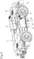
Figure 1 is a schematic side view of a telehandler according to the invention; -
Figures 2 - 6 are axonometric views of the telehandler ofFigure 1 , shown without a turret for reasons of legibility of the drawings, shown in various operating configurations and in the relative transition steps; -
Figures 7 and 8 are axonometric views of a lateral part of the carriage of the proposed telehandler showing structural and functional details of a lateral load compartment; and -
Figure 9 is an exploded view of an electricity generator apparatus which can be used together with the proposed telehandler. - With reference to the first drawing, the
numeral 1 denotes in its entirety an electrically powered telehandler according to the invention. - The
telehandler 1 proposed is equipped with aframe 11, or "carriage", movable on wheels and may be either fixed or rotary, that is to say, it can mount the cab and the operating arm directly on thecarriage 11 or, as in the case illustrated, may be equipped with a platform, or "turret" 110, mounted rotatably on thecarriage 11, which supports the cab and operating arm. - The
telehandler 1 according to the invention may comprise at least one electric drive motor positioned at one of the axles and an electric motor for driving the hydraulic pump which powers, using a distributor, the movement cylinders of thearm 111 and, if necessary, the motor-driven rack of thetower 110. - The
telehandler 1 is advantageously equipped with a plurality ofcontainment compartments 100 for housing themeans energy sources - Preferably, the
carriage 11 of the telehandler can define twolateral compartments 100, made in its opposite lateral portions, right and left, accessible on opposite sides, each of which is designed to house the above-mentioned power supply means 200, 300. - At least one of the compartments 100 (and preferably all) is provided with an access opening to allow a user to insert or extract, and in particular replace, the power supply means 200, 300.
- In detail, the access opening of the
compartment 100 may be positioned on a relative side of thecarriage 11, facing outwards, thereby allowing an insertion and an extraction of the power supply means 200, 300 along a horizontal direction (seeFigures 2 - 6 ). - The opening is equipped with a
door 101, or "hood", to allow access to thecompartment 100 from the outside; thedoor 101 may be of the tilting type and equipped with a lock. - The invention also comprises two types of electricity supply sources:
electric batteries 200 andelectricity generator apparatuses 300. - In detail, the invention uses a plurality of
electric batteries 200, each designed to be inserted in one of thecompartments 100 and at least oneelectricity generator apparatus 300 designed to be inserted in one of thecompartments 100. - The
electricity generator apparatus 300 may be designed for producing electricity by consuming fossil fuel, for example it may be a so-called "diesel-electric generator" or it may be a fuel cell or other apparatus which, starting from some form of fuel, produces electricity. - According to an important aspect of the invention, the
telehandler 1 is provided with two alternative power supply configurations, which can be switched by the action of a user: - a fully electrical configuration wherein the power supply means include only one or more
electric batteries 200; and - a hybrid configuration wherein the above-mentioned power supply means include the
electricity generator apparatus 300. - As will become clearer in the description which follows, in the fully electrical configuration, the power supply means which are on board the
telehandler 1 includebatteries 200 but notelectricity generator apparatuses 300, whilst in the hybrid configuration they include at least oneelectricity generator apparatus 300. - Preferably, in the hybrid configuration, the power supply means include an
electric battery 200 which supplies the propulsion motor and the motor which drives the pump and anelectricity generator apparatus 300 set up for charging thebattery 200. For this reason, in order to switch from the hybrid configuration to the fully electrical configuration it may also be sufficient to remove from thetelehandler 1 theelectricity generator apparatus 300 and to switch from the fully electrical configuration to the hybrid configuration it is always necessary to insert theelectricity generator apparatus 300 into one of the compartments. - Before describing further construction and functional aspects of the invention, it is briefly explained below how this overcomes the limitations of the prior art, with reference to the non-limiting example case wherein the
telehandler 1 is equipped with twocompartments 100 made in thecarriage 11, as explained above and the electricity generator apparatus is a diesel-electric generator 300. - The proposed
telehandler 1 can work, when it is in its fully electrical configuration, without restrictions in town centres or in closed environments, powered by itsbatteries 200 contained in thelateral compartments 100 of thecarriage 11. - When the work is finished, or in any case when it is necessary for the
telehandler 1 to be moved to another site which is not close by, the operator will open one of the compartments and will extract the respective battery 200 (see the sequence ofFigures 2 ,3 and4 ), unless themachine 1 is working with asingle battery 200, in which case thehood 101 of the empty compartment will be opened. - At this point, the
generator 300 will be inserted in the compartment 100 (seeFigures 5 and6 ) and will be connected to the electrical system inside thetelehandler 1, which is now in its hybrid configuration, in such a way that thegenerator 300 charges thebattery 200 contained in theother compartment 100. After that, having obtained the necessary autonomy, thetelehandler 1 can be driven to the destination. - In the same way, once a
telehandler 1 equipped on board with thegenerator 300 is carried close to a work site in which restrictions on the emissions are in force, the operators can open the compartment containing thegenerator 300, take it out, if necessary inserting in its place anelectric battery 200 and then move thetelehandler 1 in the fully electrical configuration to the work site. - It should be noted that the fact that the proposed
telehandler 1 can be switched from the hybrid configuration to the fully electrical configuration and vice versa allows customers to have aversatile machine 1 which can work in environments with emission restrictions, but has the autonomy of a traditional hybrid machine or also of a traditional diesel machine; for this reason, customers can make savings by not having to purchase a plurality of telehandlers having different power supply systems. - Advantageously, it is also possible to replace the
flat batteries 200 and thegenerators 300 which have finished the fuel. - For example, once one of the
batteries 200 according to the invention is flat, it is sufficient to open therespective compartment 100, extracting theflat battery 200, which will then be carried for recharging to a site equipped with charging means connected to the national electricity network or according to other known means. In the meantime, thetelehandler 1 can continue the programmed operations using the energy stored in theother battery 200. After that, with thefirst battery 200 recharged, it will be again transported to the work site in order, for example, to replace theother battery 200, which in the meantime has drained and so on. - In any case, even if it is equipped with two (or more)
compartments 100, thetelehandler 1 may also use only onebattery 200, if the activity for which it is used can be carried out before it drains or also use the current of both thebatteries 200 simultaneously, as described in more detail below. On the other hand, if thetelehandler 1 is equipped with asingle compartment 100, it is still possible to use twobatteries 200, so that once the battery housed in thecompartment 100 has been discharged, the other one is already available near by, to enable replacement. - Preferably, the
batteries 200 and theelectricity generator apparatuses 300 which can be replaced according to the invention are equipped, at the lower side, withinsertion seats battery 200 and theelectricity generator apparatus 300 may have a bottom which defines or consists of or is fixed to a base shaped like a pallet, for the purpose of inserting forks and the movement with a customary forklift truck. - In this case, the replacement occurs by opening the
door 101, placing forks beneath thebattery 200 or theelectricity generator apparatus 300, after electrical disconnection and extracting it from thecompartment 100 making it slide on the guide means 103, 104; subsequently, after placing forks beneath anotherbattery 200 or another electricity generator apparatus, moving it to the height of the opening and then inserting it by sliding on the guide means 103, 104, examples of which are described in more detail below. - Preferably, the
battery 200 comprises aconnector 202 for dispensing the current (possibly only one), which can be connected to a respective single transmission cable 105 (possibly only one) positioned in thecompartment 100, connected to the electrical system of thetelehandler 1 and connected to the above-mentioned electric motors, for the purposes of their power supply. The accompanying drawings also show the optional solution is shown of providing aninternal connector 102 to the compartment to which thecable 105 is attached when thedoor 101 is closed with anempty compartment 100; in this way, thetelehandler 1 can be started, using theother battery 200 without an open circuit remaining in the system. Moreover, thebattery 200 may be equipped with an ON/OFF switch 203 (indicated inFigure 7 ) which is used to disconnect it electrically, without the need to disconnect thecable 105, to prevent it from being drained during non-operating periods when it remains on board thetelehandler 1. - The invention provides optionally the use of an electricity generator apparatus consisting of a diesel-
electric generator 300 with a new design, specifically conceived to be used in the hybrid configuration of the proposed telehandler. - The
apparatus 300, as shown inFigure 9 , includes acasing 302 which firstly contains aninternal combustion engine 303, equipped with one ormore exhaust pipes 304, facing downwards for emitting the exhaust gases outside thecasing 302, aradiator 305 and a tank for thewater 306. Thetank 307 for the diesel oil which supplies theinternal combustion engine 303 may also be positioned in such a way as to form one of the walls of thecasing 302 which contains the above-mentioned components. Thecasing 302 also contains theactual generator 308, that is to say, the alternator which, driven by theinternal combustion engine 303, produces the current with which thebattery 200 of thetelehandler 1 is charged, in its hybrid configuration. - The
inverter 309 used to control this current may also be mounted on the outer surface of thecasing 302, for example above the above-mentionedtank 307 and is connected to thegenerator 308 bysuitable wiring 310. Thecasing 302 also mounts, externally, a connector 311 like that of thebattery 200, designed to be connected to the above-mentionedtransmission cable 105. - Still more in detail, the electrical system which connects the
battery 200 to the motors and theelectricity generator apparatus 300 to thebattery 200, includes all the usual electrical and electronic devices for the operation of motors and other user devices, such as inverters positioned upstream of the motors, units for distributing the power supply downstream of the batteries 200 (typically one for each battery), chargers for charging thebatteries 200 by means of an external socket (to be used if there is a power supply source close to the work site, for example a column for recharging the batteries) and the various circuits for the lighting of the flashing warning lights and reflectors, internal lighting, etc. - Preferably, as shown in
Figure 8 , the above-mentioned guide means 103, 104 include a lowershaped surface 103 of thecompartment 100, which is equipped with recesses for slidably receiving theseats 201 for inserting the prongs which are located at the lower surface of theenergy source compartment 100. - Moreover, as shown in
Figure 7 , thebattery 200 and theelectricity generator apparatus 300 may be equipped withrespective engagement elements 204, for example in the form of wings protruding from respective opposite sides; it should be noted that, although the drawing only shows the case of thebattery 200, theengagement elements 204 might also be mounted on theelectricity generator apparatus 300. - The
wings 204 which protrude from opposite lateral surfaces of theenergy source Figure 8 ), made, for example, by metal plates, which are positioned in thecompartment 100, to defineshelves 104 on which thewings 204 of thebattery 200 or of theapparatus 300, which are therefore supported by them, slide into place. - Further, releasable locking means 106, consisting, for example, of screws and/or bolts, may be provided to prevent the involuntary extraction of the
battery 200 from the inside of thecompartment 100. - Moreover, there may also be a
tilting retaining panel 107, hinged at the lower edge of the opening and which can be lowered upon completion of the extraction and insertion of thebattery 200 or of the electricity generator apparatus. - Lastly, the invention may include electronic processing means, connectable to the
battery 200 or to thebatteries 200 contained/and in thecompartment 100 and designed to adjust the supply of current. - In particular, the processing means, which may also consist of or included in or connected to the control unit usually used in
telehandlers 1, include a current regulating module configured in such a way as to adjust the supply of current of thevarious batteries 200 according to variable proportions. - In other words, if the
telehandler 1 is fitted with twobatteries 200, for example, the operator in the cab can establish, by means of a user interface connected to the processing means, how much current is to be picked up from one of thebatteries 200 relative to the other in order to supply the user devices of the vehicle; in particular cases, only onebattery 200 supplies the electric motors of thetelehandler 1 or both thebatteries 200 dispense half of the electricity requested. - In the same way, the processing means may include a control module of the
electricity generator apparatus 300, configured for adjusting its operation; again thanks to the above-mentioned interface, the operator can manage or set up the operation of theelectricity generator apparatus 300 and thebattery 200.
Claims (12)
- A telehandler (1) equipped with at least one electric propulsion motor and with several containment compartments (100) for housing means (200, 300) for powering said motor;characterized in that at least one of said compartments (100) is provided with an access opening to allow a user to insert or extract at least one source of electricity (200, 300) included in said power supply means;wherein a plurality of electric batteries (200) is made available, each designed to be inserted in one of the compartments (100);wherein at least one electricity generator apparatus (300) is provided for insertion in one of the compartments (100);wherein said telehandler (1) is equipped with two alternative power supply configurations:a fully electrical configuration wherein the above-mentioned power supply means include only one or more electric batteries (200); anda hybrid configuration wherein the above-mentioned power supply means include said electricity generator apparatus (300).
- The telehandler (1) according to the preceding claim, wherein in said hybrid configuration the power supply means include an electric battery (200) which supplies the propulsion motor and an electricity generator apparatus (300) which charges said battery (200).
- The telehandler (1) according to any one of the preceding claims, wherein said electricity generator apparatus is a diesel-electric generator (300).
- The telehandler (1) according to any one of the preceding claims, wherein the electricity generator apparatus is a fuel cell.
- The telehandler (1) according to any one of the preceding claims, which can be switched from said fully electrical configuration to said hybrid configuration, following the insertion of the electricity generator apparatus (300) in the above-mentioned compartment (100) equipped with access opening, and from the hybrid configuration to the fully electrical configuration, following the extraction of the electricity generator apparatus (300) from the compartment (100).
- The telehandler (1) according to any one of the preceding claims, wherein the compartment (100) equipped with an access opening comprises guide means (103, 104) for the sliding of a battery (200) or the electricity generator apparatus (300) during the respective insertion or extraction.
- The telehandler (1) according to any one of the preceding claims, comprising a carriage (11) movable on wheels, wherein the compartment (100) is made in said carriage (11), with the access opening positioned on a side of the carriage (11).
- The telehandler (1) according to the preceding claim, comprising two compartments (100) having the respective access openings positioned at opposite sides of the carriage (11).
- The telehandler (1) according to any one of the preceding claims, wherein the battery (200) is equipped, at a lower side, with insertion seats (201) for receiving the prongs of a loading fork, to allow the movement by means of a forklift truck.
- The telehandler (1) according to any one of the preceding claims, wherein the electricity generator apparatus (300) is equipped, at a lower side, with insertion seats (301) for receiving the prongs of a loading fork, to allow the movement by means of a forklift truck.
- The telehandler (1) according to claim 9 or 10, wherein said guide means (103, 104) include a lower surface (103) of the compartment (100) shaped in such a way as to slidably receive said insertion seats.
- The telehandler (1) according to any one of the preceding claims, comprising releasable locking means (106, 107) to prevent the involuntary extraction of the component of the power supply means from the inside of the compartment (100).
Priority Applications (4)
| Application Number | Priority Date | Filing Date | Title |
|---|---|---|---|
| SI202230110T SI4122735T1 (en) | 2021-07-21 | 2022-06-24 | Telehandler with convertible propulsion |
| SM20250140T SMT202500140T1 (en) | 2021-07-21 | 2022-06-24 | Telehandler with convertible propulsion |
| HRP20250357TT HRP20250357T1 (en) | 2021-07-21 | 2022-06-24 | TELESCOPIC LOADER WITH CONVERTIBLE DRIVE |
| RS20250289A RS66663B1 (en) | 2021-07-21 | 2022-06-24 | Telehandler with convertible propulsion |
Applications Claiming Priority (1)
| Application Number | Priority Date | Filing Date | Title |
|---|---|---|---|
| IT202100019406 | 2021-07-21 |
Publications (2)
| Publication Number | Publication Date |
|---|---|
| EP4122735A1 EP4122735A1 (en) | 2023-01-25 |
| EP4122735B1 true EP4122735B1 (en) | 2025-01-22 |
Family
ID=78086806
Family Applications (1)
| Application Number | Title | Priority Date | Filing Date |
|---|---|---|---|
| EP22181031.0A Active EP4122735B1 (en) | 2021-07-21 | 2022-06-24 | Telehandler with convertible propulsion |
Country Status (19)
| Country | Link |
|---|---|
| US (1) | US12410044B2 (en) |
| EP (1) | EP4122735B1 (en) |
| CN (1) | CN115676702A (en) |
| AU (1) | AU2022204686A1 (en) |
| BR (1) | BR102022014164A2 (en) |
| CA (1) | CA3167510A1 (en) |
| DK (1) | DK4122735T3 (en) |
| ES (1) | ES3022107T3 (en) |
| FI (1) | FI4122735T3 (en) |
| HR (1) | HRP20250357T1 (en) |
| HU (1) | HUE070766T2 (en) |
| LT (1) | LT4122735T (en) |
| MX (1) | MX2022009014A (en) |
| PL (1) | PL4122735T3 (en) |
| PT (1) | PT4122735T (en) |
| RS (1) | RS66663B1 (en) |
| SI (1) | SI4122735T1 (en) |
| SM (1) | SMT202500140T1 (en) |
| ZA (1) | ZA202207578B (en) |
Families Citing this family (5)
| Publication number | Priority date | Publication date | Assignee | Title |
|---|---|---|---|---|
| FR3137874B1 (en) * | 2022-07-18 | 2024-05-31 | Manitou Bf | Work machine with a cabin located laterally and a battery module fixed under the cabin |
| IT202200026715A1 (en) * | 2022-12-23 | 2024-06-23 | Manitou Italia Srl | Portable charging device for telehandlers. |
| IT202200026838A1 (en) * | 2022-12-27 | 2024-06-27 | Manitou Italia Srl | Telehandler with automatic recognition of energy sources. |
| IT202300014337A1 (en) * | 2023-07-10 | 2025-01-10 | Dieci S R L | ELECTRIC TELEHANDLER AND RANGE EXTENSION KIT FOR ELECTRIC TELEHANDLER |
| US20260091661A1 (en) * | 2024-10-01 | 2026-04-02 | Caterpillar Inc. | Hybrid Power System for a Machine |
Family Cites Families (25)
| Publication number | Priority date | Publication date | Assignee | Title |
|---|---|---|---|---|
| DE4140508A1 (en) * | 1991-12-09 | 1993-06-17 | Hotzenblitz Mobile Gmbh Co Kg | Steerable motor vehicle assembly - is of modular construction and is intended for use on public highway. |
| US5251721A (en) * | 1992-04-21 | 1993-10-12 | Richard Ortenheim | Semi-hybrid electric automobile |
| DE9305879U1 (en) * | 1993-04-20 | 1993-06-17 | Doppstadt, Werner, 5620 Velbert | Mounting a drive component on a mobile machine |
| DE4427322C2 (en) * | 1994-08-02 | 2000-07-27 | Wolfgang Hill | Electricity generation unit for series hybrid vehicles and combined heat and power plants |
| ATE185895T1 (en) * | 1996-08-20 | 1999-11-15 | Wegmann & Co Gmbh | COMBAT VEHICLE WITH DIESEL-ELECTRIC DRIVE AND REAR HATCH |
| US6012544A (en) * | 1997-10-24 | 2000-01-11 | Grove U.S. L.L.C. | Aerial work platform with removably attachable support structure for auxiliary power plant |
| DE10202060A1 (en) * | 2002-01-18 | 2003-08-14 | Lutz Baur | Vehicle with a drive motor |
| DE10324170A1 (en) * | 2003-05-26 | 2004-12-16 | Edag Engineering + Design Ag | Electric vehicle system |
| DE102006031461A1 (en) * | 2006-07-07 | 2008-01-10 | Jungheinrich Aktiengesellschaft | Battery replacement system for a battery-operated truck |
| GB0621306D0 (en) * | 2006-10-26 | 2006-12-06 | Wrightbus Ltd | A hybrid electric vehicle |
| CN103640556A (en) * | 2008-10-15 | 2014-03-19 | 格特拉克·福特传动系统有限公司 | Vehicle having drive train |
| EP2308708B1 (en) | 2009-09-16 | 2016-08-17 | swissauto powersport llc | Electric vehicle with range extension |
| DE102009045340A1 (en) * | 2009-09-18 | 2011-03-24 | Jungheinrich Aktiengesellschaft | Battery removal device for a vehicle, in particular electric utility vehicle, and locking device for such a battery removal device |
| US20110100735A1 (en) * | 2009-11-05 | 2011-05-05 | Ise Corporation | Propulsion Energy Storage Control System and Method of Control |
| US20110226539A1 (en) * | 2010-03-16 | 2011-09-22 | Huss Michael A | Vehicle with removable auxiliary power system |
| DE102011115570B4 (en) * | 2011-10-10 | 2016-11-17 | MULAG FAHRZEUGWERK Heinz Wössner GmbH & Co. KG | Tractor with different energy supply unit |
| EP3025889A4 (en) * | 2013-07-24 | 2017-03-08 | Aleees Eco Ark (Cayman) Co. LTD. | Detachable high-voltage isolation structure of large-sized electric vehicle |
| FI20155518A7 (en) | 2015-06-30 | 2016-12-31 | Dinolift Oy | Reach lifter |
| DE102018115036A1 (en) * | 2018-06-22 | 2019-12-24 | Weidemann GmbH | Work vehicle with electrical energy storage |
| CA3050527A1 (en) * | 2018-07-27 | 2020-01-27 | Manitou Italia S.R.L. | Improved electric telehandler |
| CA3128026C (en) * | 2019-01-29 | 2026-03-03 | Haulotte Group | Elevating nacelle suitable for indoor and all-terrain outdoor use |
| US12337718B2 (en) * | 2019-05-03 | 2025-06-24 | Oshkosh Corporation | Battery storage system for electric refuse vehicle |
| US11007863B2 (en) | 2019-07-31 | 2021-05-18 | Oshkosh Corporation | Refuse vehicle with independently operational accessory system |
| CN112060971A (en) * | 2020-09-30 | 2020-12-11 | 浙江吉利控股集团有限公司 | A battery-swappable hybrid vehicle |
| IT202200026838A1 (en) * | 2022-12-27 | 2024-06-27 | Manitou Italia Srl | Telehandler with automatic recognition of energy sources. |
-
2022
- 2022-06-24 HU HUE22181031A patent/HUE070766T2/en unknown
- 2022-06-24 ES ES22181031T patent/ES3022107T3/en active Active
- 2022-06-24 EP EP22181031.0A patent/EP4122735B1/en active Active
- 2022-06-24 PL PL22181031.0T patent/PL4122735T3/en unknown
- 2022-06-24 SI SI202230110T patent/SI4122735T1/en unknown
- 2022-06-24 HR HRP20250357TT patent/HRP20250357T1/en unknown
- 2022-06-24 LT LTEP22181031.0T patent/LT4122735T/en unknown
- 2022-06-24 SM SM20250140T patent/SMT202500140T1/en unknown
- 2022-06-24 PT PT221810310T patent/PT4122735T/en unknown
- 2022-06-24 RS RS20250289A patent/RS66663B1/en unknown
- 2022-06-24 DK DK22181031.0T patent/DK4122735T3/en active
- 2022-06-24 FI FIEP22181031.0T patent/FI4122735T3/en active
- 2022-06-30 AU AU2022204686A patent/AU2022204686A1/en active Pending
- 2022-07-08 ZA ZA2022/07578A patent/ZA202207578B/en unknown
- 2022-07-13 CA CA3167510A patent/CA3167510A1/en active Pending
- 2022-07-18 BR BR102022014164-9A patent/BR102022014164A2/en unknown
- 2022-07-20 MX MX2022009014A patent/MX2022009014A/en unknown
- 2022-07-20 US US17/868,842 patent/US12410044B2/en active Active
- 2022-07-20 CN CN202210872527.8A patent/CN115676702A/en active Pending
Also Published As
| Publication number | Publication date |
|---|---|
| US20230026643A1 (en) | 2023-01-26 |
| FI4122735T3 (en) | 2025-03-27 |
| PT4122735T (en) | 2025-03-27 |
| US12410044B2 (en) | 2025-09-09 |
| CA3167510A1 (en) | 2023-01-21 |
| ES3022107T3 (en) | 2025-05-28 |
| HRP20250357T1 (en) | 2025-05-09 |
| CN115676702A (en) | 2023-02-03 |
| RS66663B1 (en) | 2025-05-30 |
| EP4122735A1 (en) | 2023-01-25 |
| BR102022014164A2 (en) | 2023-01-31 |
| AU2022204686A1 (en) | 2023-02-09 |
| SMT202500140T1 (en) | 2025-05-12 |
| HUE070766T2 (en) | 2025-07-28 |
| ZA202207578B (en) | 2023-04-26 |
| SI4122735T1 (en) | 2025-05-30 |
| PL4122735T3 (en) | 2025-04-28 |
| DK4122735T3 (en) | 2025-03-24 |
| LT4122735T (en) | 2025-03-25 |
| MX2022009014A (en) | 2023-01-23 |
Similar Documents
| Publication | Publication Date | Title |
|---|---|---|
| EP4122735B1 (en) | Telehandler with convertible propulsion | |
| US11993496B2 (en) | Electric telehandler | |
| US12409754B2 (en) | Battery storage system for electrified vehicle | |
| US20240208352A1 (en) | Portable charger device for telehandler | |
| US10589633B2 (en) | Fast charging battery system | |
| US10773602B2 (en) | Electrified vehicles with removable and interchangeable range extending generators | |
| AU2022313535A1 (en) | Self-propelling piece of lifting machinery having a main electrical power source and able to accommodate various interchangeable secondary electrical power sources | |
| EP4393865A1 (en) | Telehandler with automatic recognition of energy sources | |
| RU2843316C2 (en) | Telescopic loader with transformable power plant | |
| RU2843316C9 (en) | Telescopic loader with transformable power plant | |
| RU2854802C2 (en) | Improved electric telescopic loader | |
| US20240075831A1 (en) | Method, Portable Detachable Battery, Mounted Apparatuses configured for All-Electric On-Board Vehicle Electrification. | |
| US20250100401A1 (en) | Road construction machine | |
| RU2796465C1 (en) | Advanced electric telescopic handler | |
| WO2010035275A1 (en) | Auxiliary power unit having self-contained electric power distribution | |
| WO2026062252A1 (en) | Interchangeable trolley module for electric vehicle | |
| BR102023027370A2 (en) | PORTABLE CHARGING DEVICE FOR TELESCOPIC HANDLER | |
| BR112020024804B1 (en) | MOBILE WORK SYSTEM AND METHOD FOR OPERATING AN ACCESSORY |
Legal Events
| Date | Code | Title | Description |
|---|---|---|---|
| REG | Reference to a national code |
Ref country code: HR Ref legal event code: TUEP Ref document number: P20250357T Country of ref document: HR |
|
| PUAI | Public reference made under article 153(3) epc to a published international application that has entered the european phase |
Free format text: ORIGINAL CODE: 0009012 |
|
| STAA | Information on the status of an ep patent application or granted ep patent |
Free format text: STATUS: THE APPLICATION HAS BEEN PUBLISHED |
|
| AK | Designated contracting states |
Kind code of ref document: A1 Designated state(s): AL AT BE BG CH CY CZ DE DK EE ES FI FR GB GR HR HU IE IS IT LI LT LU LV MC MK MT NL NO PL PT RO RS SE SI SK SM TR |
|
| STAA | Information on the status of an ep patent application or granted ep patent |
Free format text: STATUS: REQUEST FOR EXAMINATION WAS MADE |
|
| P01 | Opt-out of the competence of the unified patent court (upc) registered |
Effective date: 20230614 |
|
| 17P | Request for examination filed |
Effective date: 20230712 |
|
| RBV | Designated contracting states (corrected) |
Designated state(s): AL AT BE BG CH CY CZ DE DK EE ES FI FR GB GR HR HU IE IS IT LI LT LU LV MC MK MT NL NO PL PT RO RS SE SI SK SM TR |
|
| GRAP | Despatch of communication of intention to grant a patent |
Free format text: ORIGINAL CODE: EPIDOSNIGR1 |
|
| STAA | Information on the status of an ep patent application or granted ep patent |
Free format text: STATUS: GRANT OF PATENT IS INTENDED |
|
| INTG | Intention to grant announced |
Effective date: 20240819 |
|
| GRAS | Grant fee paid |
Free format text: ORIGINAL CODE: EPIDOSNIGR3 |
|
| GRAA | (expected) grant |
Free format text: ORIGINAL CODE: 0009210 |
|
| STAA | Information on the status of an ep patent application or granted ep patent |
Free format text: STATUS: THE PATENT HAS BEEN GRANTED |
|
| AK | Designated contracting states |
Kind code of ref document: B1 Designated state(s): AL AT BE BG CH CY CZ DE DK EE ES FI FR GB GR HR HU IE IS IT LI LT LU LV MC MK MT NL NO PL PT RO RS SE SI SK SM TR |
|
| REG | Reference to a national code |
Ref country code: GB Ref legal event code: FG4D |
|
| REG | Reference to a national code |
Ref country code: CH Ref legal event code: EP |
|
| REG | Reference to a national code |
Ref country code: IE Ref legal event code: FG4D |
|
| REG | Reference to a national code |
Ref country code: DE Ref legal event code: R096 Ref document number: 602022009732 Country of ref document: DE |
|
| REG | Reference to a national code |
Ref country code: NL Ref legal event code: FP |
|
| REG | Reference to a national code |
Ref country code: DK Ref legal event code: T3 Effective date: 20250318 |
|
| REG | Reference to a national code |
Ref country code: PT Ref legal event code: SC4A Ref document number: 4122735 Country of ref document: PT Date of ref document: 20250327 Kind code of ref document: T Free format text: AVAILABILITY OF NATIONAL TRANSLATION Effective date: 20250321 Ref country code: FI Ref legal event code: FGE |
|
| REG | Reference to a national code |
Ref country code: SE Ref legal event code: TRGR |
|
| REG | Reference to a national code |
Ref country code: HR Ref legal event code: T1PR Ref document number: P20250357 Country of ref document: HR |
|
| REG | Reference to a national code |
Ref country code: SK Ref legal event code: T3 Ref document number: E 46204 Country of ref document: SK Ref country code: ES Ref legal event code: FG2A Ref document number: 3022107 Country of ref document: ES Kind code of ref document: T3 Effective date: 20250528 |
|
| REG | Reference to a national code |
Ref country code: GR Ref legal event code: EP Ref document number: 20250400642 Country of ref document: GR Effective date: 20250514 |
|
| REG | Reference to a national code |
Ref country code: EE Ref legal event code: FG4A Ref document number: E024996 Country of ref document: EE Effective date: 20250320 |
|
| PGFP | Annual fee paid to national office [announced via postgrant information from national office to epo] |
Ref country code: SM Payment date: 20250529 Year of fee payment: 4 |
|
| REG | Reference to a national code |
Ref country code: HR Ref legal event code: ODRP Ref document number: P20250357 Country of ref document: HR Payment date: 20250604 Year of fee payment: 4 |
|
| PGFP | Annual fee paid to national office [announced via postgrant information from national office to epo] |
Ref country code: MC Payment date: 20250618 Year of fee payment: 4 |
|
| PGFP | Annual fee paid to national office [announced via postgrant information from national office to epo] |
Ref country code: FI Payment date: 20250624 Year of fee payment: 4 |
|
| PGFP | Annual fee paid to national office [announced via postgrant information from national office to epo] |
Ref country code: PL Payment date: 20250603 Year of fee payment: 4 Ref country code: DE Payment date: 20250626 Year of fee payment: 4 |
|
| PGFP | Annual fee paid to national office [announced via postgrant information from national office to epo] |
Ref country code: DK Payment date: 20250619 Year of fee payment: 4 |
|
| PGFP | Annual fee paid to national office [announced via postgrant information from national office to epo] |
Ref country code: LT Payment date: 20250604 Year of fee payment: 4 |
|
| PGFP | Annual fee paid to national office [announced via postgrant information from national office to epo] |
Ref country code: IS Payment date: 20250630 Year of fee payment: 4 Ref country code: RS Payment date: 20250603 Year of fee payment: 4 Ref country code: NO Payment date: 20250617 Year of fee payment: 4 |
|
| PGFP | Annual fee paid to national office [announced via postgrant information from national office to epo] |
Ref country code: LU Payment date: 20250624 Year of fee payment: 4 Ref country code: AL Payment date: 20250630 Year of fee payment: 4 Ref country code: NL Payment date: 20250624 Year of fee payment: 4 Ref country code: BE Payment date: 20250624 Year of fee payment: 4 |
|
| PGFP | Annual fee paid to national office [announced via postgrant information from national office to epo] |
Ref country code: HR Payment date: 20250604 Year of fee payment: 4 |
|
| PGFP | Annual fee paid to national office [announced via postgrant information from national office to epo] |
Ref country code: LV Payment date: 20250625 Year of fee payment: 4 Ref country code: PT Payment date: 20250603 Year of fee payment: 4 |
|
| PGFP | Annual fee paid to national office [announced via postgrant information from national office to epo] |
Ref country code: EE Payment date: 20250626 Year of fee payment: 4 Ref country code: HU Payment date: 20250612 Year of fee payment: 4 Ref country code: FR Payment date: 20250624 Year of fee payment: 4 |
|
| PGFP | Annual fee paid to national office [announced via postgrant information from national office to epo] |
Ref country code: GR Payment date: 20250619 Year of fee payment: 4 Ref country code: MT Payment date: 20250625 Year of fee payment: 4 Ref country code: BG Payment date: 20250625 Year of fee payment: 4 |
|
| PGFP | Annual fee paid to national office [announced via postgrant information from national office to epo] |
Ref country code: AT Payment date: 20250721 Year of fee payment: 4 |
|
| PGFP | Annual fee paid to national office [announced via postgrant information from national office to epo] |
Ref country code: TR Payment date: 20250604 Year of fee payment: 4 Ref country code: SK Payment date: 20250609 Year of fee payment: 4 |
|
| PGFP | Annual fee paid to national office [announced via postgrant information from national office to epo] |
Ref country code: CZ Payment date: 20250609 Year of fee payment: 4 |
|
| REG | Reference to a national code |
Ref country code: HU Ref legal event code: AG4A Ref document number: E070766 Country of ref document: HU |
|
| PGFP | Annual fee paid to national office [announced via postgrant information from national office to epo] |
Ref country code: IE Payment date: 20250617 Year of fee payment: 4 |
|
| PGFP | Annual fee paid to national office [announced via postgrant information from national office to epo] |
Ref country code: SE Payment date: 20250619 Year of fee payment: 4 Ref country code: SI Payment date: 20250609 Year of fee payment: 4 |
|
| PGFP | Annual fee paid to national office [announced via postgrant information from national office to epo] |
Ref country code: ES Payment date: 20250710 Year of fee payment: 4 |
|
| PGFP | Annual fee paid to national office [announced via postgrant information from national office to epo] |
Ref country code: IT Payment date: 20250630 Year of fee payment: 4 |
|
| PGFP | Annual fee paid to national office [announced via postgrant information from national office to epo] |
Ref country code: CH Payment date: 20250701 Year of fee payment: 4 |
|
| REG | Reference to a national code |
Ref country code: DE Ref legal event code: R097 Ref document number: 602022009732 Country of ref document: DE |
|
| PG25 | Lapsed in a contracting state [announced via postgrant information from national office to epo] |
Ref country code: RO Free format text: LAPSE BECAUSE OF FAILURE TO SUBMIT A TRANSLATION OF THE DESCRIPTION OR TO PAY THE FEE WITHIN THE PRESCRIBED TIME-LIMIT Effective date: 20250122 |
|
| PGFP | Annual fee paid to national office [announced via postgrant information from national office to epo] |
Ref country code: MK Payment date: 20250609 Year of fee payment: 4 |
|
| PLBE | No opposition filed within time limit |
Free format text: ORIGINAL CODE: 0009261 |
|
| STAA | Information on the status of an ep patent application or granted ep patent |
Free format text: STATUS: NO OPPOSITION FILED WITHIN TIME LIMIT |
|
| 26N | No opposition filed |
Effective date: 20251023 |
|
| PGFP | Annual fee paid to national office [announced via postgrant information from national office to epo] |
Ref country code: CY Payment date: 20250530 Year of fee payment: 4 |
|
| PG2D | Information on lapse in contracting state deleted |
Ref country code: RO |
|
| PGFP | Annual fee paid to national office [announced via postgrant information from national office to epo] |
Ref country code: RO Payment date: 20250610 Year of fee payment: 4 |
|
| REG | Reference to a national code |
Ref country code: AT Ref legal event code: UEP Ref document number: 1761226 Country of ref document: AT Kind code of ref document: T Effective date: 20250122 |