EP4122683A1 - A method for manufacturing a structural element for a fuselage of an aircraft - Google Patents
A method for manufacturing a structural element for a fuselage of an aircraft Download PDFInfo
- Publication number
- EP4122683A1 EP4122683A1 EP21187300.5A EP21187300A EP4122683A1 EP 4122683 A1 EP4122683 A1 EP 4122683A1 EP 21187300 A EP21187300 A EP 21187300A EP 4122683 A1 EP4122683 A1 EP 4122683A1
- Authority
- EP
- European Patent Office
- Prior art keywords
- structural
- mandrel
- textile material
- structural element
- material members
- Prior art date
- Legal status (The legal status is an assumption and is not a legal conclusion. Google has not performed a legal analysis and makes no representation as to the accuracy of the status listed.)
- Pending
Links
Images


Classifications
-
- B—PERFORMING OPERATIONS; TRANSPORTING
- B64—AIRCRAFT; AVIATION; COSMONAUTICS
- B64C—AEROPLANES; HELICOPTERS
- B64C1/00—Fuselages; Constructional features common to fuselages, wings, stabilising surfaces or the like
- B64C1/06—Frames; Stringers; Longerons ; Fuselage sections
- B64C1/12—Construction or attachment of skin panels
-
- B—PERFORMING OPERATIONS; TRANSPORTING
- B29—WORKING OF PLASTICS; WORKING OF SUBSTANCES IN A PLASTIC STATE IN GENERAL
- B29C—SHAPING OR JOINING OF PLASTICS; SHAPING OF MATERIAL IN A PLASTIC STATE, NOT OTHERWISE PROVIDED FOR; AFTER-TREATMENT OF THE SHAPED PRODUCTS, e.g. REPAIRING
- B29C70/00—Shaping composites, i.e. plastics material comprising reinforcements, fillers or preformed parts, e.g. inserts
- B29C70/04—Shaping composites, i.e. plastics material comprising reinforcements, fillers or preformed parts, e.g. inserts comprising reinforcements only, e.g. self-reinforcing plastics
- B29C70/28—Shaping operations therefor
- B29C70/30—Shaping by lay-up, i.e. applying fibres, tape or broadsheet on a mould, former or core; Shaping by spray-up, i.e. spraying of fibres on a mould, former or core
- B29C70/32—Shaping by lay-up, i.e. applying fibres, tape or broadsheet on a mould, former or core; Shaping by spray-up, i.e. spraying of fibres on a mould, former or core on a rotating mould, former or core
-
- B—PERFORMING OPERATIONS; TRANSPORTING
- B29—WORKING OF PLASTICS; WORKING OF SUBSTANCES IN A PLASTIC STATE IN GENERAL
- B29C—SHAPING OR JOINING OF PLASTICS; SHAPING OF MATERIAL IN A PLASTIC STATE, NOT OTHERWISE PROVIDED FOR; AFTER-TREATMENT OF THE SHAPED PRODUCTS, e.g. REPAIRING
- B29C70/00—Shaping composites, i.e. plastics material comprising reinforcements, fillers or preformed parts, e.g. inserts
- B29C70/04—Shaping composites, i.e. plastics material comprising reinforcements, fillers or preformed parts, e.g. inserts comprising reinforcements only, e.g. self-reinforcing plastics
- B29C70/06—Fibrous reinforcements only
- B29C70/10—Fibrous reinforcements only characterised by the structure of fibrous reinforcements, e.g. hollow fibres
- B29C70/16—Fibrous reinforcements only characterised by the structure of fibrous reinforcements, e.g. hollow fibres using fibres of substantial or continuous length
- B29C70/22—Fibrous reinforcements only characterised by the structure of fibrous reinforcements, e.g. hollow fibres using fibres of substantial or continuous length oriented in at least two directions forming a two-dimensional [2D] structure
-
- B—PERFORMING OPERATIONS; TRANSPORTING
- B29—WORKING OF PLASTICS; WORKING OF SUBSTANCES IN A PLASTIC STATE IN GENERAL
- B29C—SHAPING OR JOINING OF PLASTICS; SHAPING OF MATERIAL IN A PLASTIC STATE, NOT OTHERWISE PROVIDED FOR; AFTER-TREATMENT OF THE SHAPED PRODUCTS, e.g. REPAIRING
- B29C70/00—Shaping composites, i.e. plastics material comprising reinforcements, fillers or preformed parts, e.g. inserts
- B29C70/04—Shaping composites, i.e. plastics material comprising reinforcements, fillers or preformed parts, e.g. inserts comprising reinforcements only, e.g. self-reinforcing plastics
- B29C70/28—Shaping operations therefor
- B29C70/30—Shaping by lay-up, i.e. applying fibres, tape or broadsheet on a mould, former or core; Shaping by spray-up, i.e. spraying of fibres on a mould, former or core
-
- B—PERFORMING OPERATIONS; TRANSPORTING
- B29—WORKING OF PLASTICS; WORKING OF SUBSTANCES IN A PLASTIC STATE IN GENERAL
- B29C—SHAPING OR JOINING OF PLASTICS; SHAPING OF MATERIAL IN A PLASTIC STATE, NOT OTHERWISE PROVIDED FOR; AFTER-TREATMENT OF THE SHAPED PRODUCTS, e.g. REPAIRING
- B29C70/00—Shaping composites, i.e. plastics material comprising reinforcements, fillers or preformed parts, e.g. inserts
- B29C70/04—Shaping composites, i.e. plastics material comprising reinforcements, fillers or preformed parts, e.g. inserts comprising reinforcements only, e.g. self-reinforcing plastics
- B29C70/28—Shaping operations therefor
- B29C70/30—Shaping by lay-up, i.e. applying fibres, tape or broadsheet on a mould, former or core; Shaping by spray-up, i.e. spraying of fibres on a mould, former or core
- B29C70/38—Automated lay-up, e.g. using robots, laying filaments according to predetermined patterns
- B29C70/382—Automated fiber placement [AFP]
-
- B—PERFORMING OPERATIONS; TRANSPORTING
- B29—WORKING OF PLASTICS; WORKING OF SUBSTANCES IN A PLASTIC STATE IN GENERAL
- B29C—SHAPING OR JOINING OF PLASTICS; SHAPING OF MATERIAL IN A PLASTIC STATE, NOT OTHERWISE PROVIDED FOR; AFTER-TREATMENT OF THE SHAPED PRODUCTS, e.g. REPAIRING
- B29C70/00—Shaping composites, i.e. plastics material comprising reinforcements, fillers or preformed parts, e.g. inserts
- B29C70/04—Shaping composites, i.e. plastics material comprising reinforcements, fillers or preformed parts, e.g. inserts comprising reinforcements only, e.g. self-reinforcing plastics
- B29C70/28—Shaping operations therefor
- B29C70/30—Shaping by lay-up, i.e. applying fibres, tape or broadsheet on a mould, former or core; Shaping by spray-up, i.e. spraying of fibres on a mould, former or core
- B29C70/38—Automated lay-up, e.g. using robots, laying filaments according to predetermined patterns
- B29C70/386—Automated tape laying [ATL]
-
- B—PERFORMING OPERATIONS; TRANSPORTING
- B29—WORKING OF PLASTICS; WORKING OF SUBSTANCES IN A PLASTIC STATE IN GENERAL
- B29C—SHAPING OR JOINING OF PLASTICS; SHAPING OF MATERIAL IN A PLASTIC STATE, NOT OTHERWISE PROVIDED FOR; AFTER-TREATMENT OF THE SHAPED PRODUCTS, e.g. REPAIRING
- B29C70/00—Shaping composites, i.e. plastics material comprising reinforcements, fillers or preformed parts, e.g. inserts
- B29C70/04—Shaping composites, i.e. plastics material comprising reinforcements, fillers or preformed parts, e.g. inserts comprising reinforcements only, e.g. self-reinforcing plastics
- B29C70/28—Shaping operations therefor
- B29C70/54—Component parts, details or accessories; Auxiliary operations, e.g. feeding or storage of prepregs or SMC after impregnation or during ageing
- B29C70/545—Perforating, cutting or machining during or after moulding
-
- B—PERFORMING OPERATIONS; TRANSPORTING
- B29—WORKING OF PLASTICS; WORKING OF SUBSTANCES IN A PLASTIC STATE IN GENERAL
- B29D—PRODUCING PARTICULAR ARTICLES FROM PLASTICS OR FROM SUBSTANCES IN A PLASTIC STATE
- B29D99/00—Subject matter not provided for in other groups of this subclass
- B29D99/0003—Producing profiled members, e.g. beams
-
- B—PERFORMING OPERATIONS; TRANSPORTING
- B29—WORKING OF PLASTICS; WORKING OF SUBSTANCES IN A PLASTIC STATE IN GENERAL
- B29D—PRODUCING PARTICULAR ARTICLES FROM PLASTICS OR FROM SUBSTANCES IN A PLASTIC STATE
- B29D99/00—Subject matter not provided for in other groups of this subclass
- B29D99/001—Producing wall or panel-like structures, e.g. for hulls, fuselages, or buildings
-
- B—PERFORMING OPERATIONS; TRANSPORTING
- B64—AIRCRAFT; AVIATION; COSMONAUTICS
- B64C—AEROPLANES; HELICOPTERS
- B64C1/00—Fuselages; Constructional features common to fuselages, wings, stabilising surfaces or the like
- B64C1/14—Windows; Doors; Hatch covers or access panels; Surrounding frame structures; Canopies; Windscreens accessories therefor, e.g. pressure sensors, water deflectors, hinges, seals, handles, latches, windscreen wipers
- B64C1/1407—Doors; surrounding frames
- B64C1/1461—Structures of doors or surrounding frames
-
- B—PERFORMING OPERATIONS; TRANSPORTING
- B64—AIRCRAFT; AVIATION; COSMONAUTICS
- B64F—GROUND OR AIRCRAFT-CARRIER-DECK INSTALLATIONS SPECIALLY ADAPTED FOR USE IN CONNECTION WITH AIRCRAFT; DESIGNING, MANUFACTURING, ASSEMBLING, CLEANING, MAINTAINING OR REPAIRING AIRCRAFT, NOT OTHERWISE PROVIDED FOR; HANDLING, TRANSPORTING, TESTING OR INSPECTING AIRCRAFT COMPONENTS, NOT OTHERWISE PROVIDED FOR
- B64F5/00—Designing, manufacturing, assembling, cleaning, maintaining or repairing aircraft, not otherwise provided for; Handling, transporting, testing or inspecting aircraft components, not otherwise provided for
- B64F5/10—Manufacturing or assembling aircraft, e.g. jigs therefor
-
- B—PERFORMING OPERATIONS; TRANSPORTING
- B29—WORKING OF PLASTICS; WORKING OF SUBSTANCES IN A PLASTIC STATE IN GENERAL
- B29C—SHAPING OR JOINING OF PLASTICS; SHAPING OF MATERIAL IN A PLASTIC STATE, NOT OTHERWISE PROVIDED FOR; AFTER-TREATMENT OF THE SHAPED PRODUCTS, e.g. REPAIRING
- B29C2793/00—Shaping techniques involving a cutting or machining operation
- B29C2793/009—Shaping techniques involving a cutting or machining operation after shaping
-
- B—PERFORMING OPERATIONS; TRANSPORTING
- B29—WORKING OF PLASTICS; WORKING OF SUBSTANCES IN A PLASTIC STATE IN GENERAL
- B29K—INDEXING SCHEME ASSOCIATED WITH SUBCLASSES B29B, B29C OR B29D, RELATING TO MOULDING MATERIALS OR TO MATERIALS FOR MOULDS, REINFORCEMENTS, FILLERS OR PREFORMED PARTS, e.g. INSERTS
- B29K2105/00—Condition, form or state of moulded material or of the material to be shaped
- B29K2105/06—Condition, form or state of moulded material or of the material to be shaped containing reinforcements, fillers or inserts
- B29K2105/08—Condition, form or state of moulded material or of the material to be shaped containing reinforcements, fillers or inserts of continuous length, e.g. cords, rovings, mats, fabrics, strands or yarns
- B29K2105/10—Cords, strands or rovings, e.g. oriented cords, strands or rovings
- B29K2105/101—Oriented
- B29K2105/102—Oriented circumferentially
-
- B—PERFORMING OPERATIONS; TRANSPORTING
- B29—WORKING OF PLASTICS; WORKING OF SUBSTANCES IN A PLASTIC STATE IN GENERAL
- B29K—INDEXING SCHEME ASSOCIATED WITH SUBCLASSES B29B, B29C OR B29D, RELATING TO MOULDING MATERIALS OR TO MATERIALS FOR MOULDS, REINFORCEMENTS, FILLERS OR PREFORMED PARTS, e.g. INSERTS
- B29K2105/00—Condition, form or state of moulded material or of the material to be shaped
- B29K2105/25—Solid
- B29K2105/253—Preform
-
- B—PERFORMING OPERATIONS; TRANSPORTING
- B29—WORKING OF PLASTICS; WORKING OF SUBSTANCES IN A PLASTIC STATE IN GENERAL
- B29L—INDEXING SCHEME ASSOCIATED WITH SUBCLASS B29C, RELATING TO PARTICULAR ARTICLES
- B29L2031/00—Other particular articles
- B29L2031/30—Vehicles, e.g. ships or aircraft, or body parts thereof
- B29L2031/3076—Aircrafts
- B29L2031/3082—Fuselages
-
- B—PERFORMING OPERATIONS; TRANSPORTING
- B64—AIRCRAFT; AVIATION; COSMONAUTICS
- B64C—AEROPLANES; HELICOPTERS
- B64C1/00—Fuselages; Constructional features common to fuselages, wings, stabilising surfaces or the like
- B64C2001/0054—Fuselage structures substantially made from particular materials
- B64C2001/0072—Fuselage structures substantially made from particular materials from composite materials
-
- Y—GENERAL TAGGING OF NEW TECHNOLOGICAL DEVELOPMENTS; GENERAL TAGGING OF CROSS-SECTIONAL TECHNOLOGIES SPANNING OVER SEVERAL SECTIONS OF THE IPC; TECHNICAL SUBJECTS COVERED BY FORMER USPC CROSS-REFERENCE ART COLLECTIONS [XRACs] AND DIGESTS
- Y02—TECHNOLOGIES OR APPLICATIONS FOR MITIGATION OR ADAPTATION AGAINST CLIMATE CHANGE
- Y02T—CLIMATE CHANGE MITIGATION TECHNOLOGIES RELATED TO TRANSPORTATION
- Y02T50/00—Aeronautics or air transport
- Y02T50/40—Weight reduction
Definitions
- the invention relates to a method for manufacturing a structural element for a fuselage of an aircraft.
- the invention relates further to specific structural parts that employ said structural element.
- EP 3 165 448 B1 discloses a method for manufacturing an aperture surrounding frame.
- a single tubular braided member is cut and layed up around an inner mold. Subsequently, the tubular member is formed and cured to obtain the aperture surrounding frame.
- Cut-outs in aircraft fuselages such as for doors (be it passenger doors, cargo doors or the like) and windows, as well as the doors themselves usually have structural elements for reinforcement.
- the structural elements are usually manufactured separately and attached to the door, for example, by bolting.
- many reinforcement structures have a ring-like structure. Their manufacture is typically high-effort and therefore high cost.
- the invention provides a method for manufacturing a structural element for a fuselage of an aircraft, the method comprising:
- step a) the textile material members are layed up on the mandrel such that a plurality of structural element preforms are spaced apart along the longitudinal direction.
- the mandrel is a split mandrel or half-size mandrel.
- the textile material members are layed up on a circumferential surface of the mandrel, so as to form a closed loop structural element preform.
- the structural element preforms are cured to obtain an annular structural element.
- the method comprises a step c) in which the mandrel is removed by pulling off the structural elements from the mandrel or by moving separate portions of the mandrel relative to each other.
- step a) the laying up is done by winding around the mandrel, automated fiber placement, automated tape layering of the textile material members.
- the textile material members are chosen from a group consisting of textile material, fiber composite material, tows, slit tape, fiber tape, non-crimp fabric, non-woven fabric, and prepregs.
- step b) at least one structural element preform is layed up by laying up the textile material members on the mandrel such that the structural element preform is double-curved.
- a first curvature is formed by continuously displacing the textile material members during laying up along the longitudinal axis up to a maximum displacement.
- a second curvature is formed by laying up the textile material members around a circumferential surface of the mandrel.
- the first curvature is further formed by continuously displacing the textile material members during laying up in an opposite direction along the longitudinal axis from the maximum displacement until the textile material members form a closed loop structural element preform.
- the invention provides a method for manufacturing a structural frame element for a cut-out in a fuselage, such as a window frame or a door frame, of an aircraft, the method comprising the step of performing a preferred method such that an annular structural element is formed that is adapted to be arranged to surround the cut-out in the fuselage and to be arranged in between skins of the fuselage.
- the invention provides a method for manufacturing a stiffened structural panel element of an aircraft, the method comprising the steps of:
- step c) the annular structural elements are affixed, so as to form a structural grid.
- step c) the annular structural elements are affixed, so that adjacent annular structural elements engage each other at an engagement location.
- the annular structural elements are fixed to each other at the engagement locations.
- the annular structural elements are affixed to the panel member by bonding, welding or bolting.
- the annular structural elements are fixed to each other by bonding, welding or bolting.
- the invention provides a structural frame element or a stiffened structural panel element obtainable by a preferred method.
- the disclosed invention relates to the field of concepts and manufacturing of aircraft structural elements.
- the structural elements are preferably used in a composite substructure for cut-out (opening) reinforcement.
- Preferably thermoplastic matrix systems are used for the structural elements.
- the substructures have a ring shape, meaning they circumferentially surround an axis in which the substructure extends.
- ring shape or annular does not imply that those parts are circular. Rather as used herein, any shape that surrounds a (central) element axis is ring-shaped or annular within the meaning of this disclosure.
- the ideas disclosed herein are applicable to structural elements that previously were produced by manufacturing skin and stiffening elements, and were assembly mainly by bolting. According to the invention fewer parts are needed, which considerably reduces the assembly effort. For cut-outs, it is possible to replace the currently different concepts, for example the deep drawn elements for the waste water panel. Furthermore, the ideas herein are able to improve the manufacture of the backup structures of panels and doors that may be used to close-off the cut-outs. In terms of weight efficiency ring-like or annular structures as envisaged herein can offer a better performance e.g. due to better following the shape of the cut-out.
- backup structures for reinforcement of the cut-out and backup structures for a door that closes the cut-out and has a panel that is supported by another backup structure.
- An important element of this idea is a (vertical flange) structural element that is of annular shape.
- the proposed concept is attractive for repetitive ring elements with roughly the same shape. Therefore it is possible with the invention to manufacture large quantities in one-shot.
- the methods allow a significant reduction of parts (ideally main structural elements are reduced to one or two parts).
- the design is made of composite material and light-weight.
- the manufacturing effort can be reduced by an efficient part sub-assembly for doors, cut-outs and the like, by preferably co-consolidation or local over molding of the substructure. In case of thermosetting matrix material co-infusion is also possible.
- the cut-out surround structure can be integrated directly on a panel/skin by local over molding or an autoclave process. If need be, flanges can be integrated into the reinforcement ring upfront for better integration into the pre-assembled structure in a second step (e.g. by bolting, bonding or welding. Faster processing times and less scrap can be achieved for single parts. In addition the same can be achieved for the assembled part due to higher integration. With the ideas herein, the overall lead time can be reduce, in particular with respect to assembly time. Integration can be achieved without dust (carbon dust for example) when co-consolidating. The invention allows for a high production rate. The disclosed ideas are a manufacturing/technology approach that can be applied for almost all kinds of shell/panel structures that are supporting cut-outs.
- a bulk door contains a panel, a grid and a surrounding edge member.
- the edge member is a ring structure.
- layup of the material on the mandrel can be done with different processes, such as winding of tows (dry, wet etc.), automated fiber placement (AFP) slit tape, automated tape layering or manually. It is possible to use wet or dry materials (e.g. non-crimp fiber, fabric).
- a sub-sequent machining e.g. waterjet cutting or milling
- This allows to have rings that can be used as stiffener in double curved areas. Additionally machining can be done in the needed angle and areas which are not needed can be cut away.
- each part can be manufactured without unique tooling.
- the single part effort is mainly caused by the major process steps which are more or less the same as if one large integrated part is manufactured.
- Another benefit can be a faster layup and less scrap by manufacturing multiple parts one shot on one larger tool.
- This concept can be transferred to all ring-shaped structural elements, such as a panel with a reinforcing substructure that is made of rings that are connected to form a grid pattern for reinforcement.
- An example is an (iso)-grid formed by circles, squares or the like.
- These ring elements can be integrated by bonding or welding (e.g. if thermoplastic resin is used).
- the ring are welded or molten together to form a larger structure.
- the ring elements can differ in shape, size, height, and/or their joining locations between the rings.
- the elements can act as load introduction (e.g. to connect beams) and allow a "dust-free" connection for assembly of later attached elements (modules) including tolerance compensation.
- the ring elements can be connected to each other by connection of their surfaces by bonding, welding or bolting. Welding has the advantage of being fast an cheap. Using bonding agent allows for a filler from the ring web to the panel to which it is affixed. Bolting is an option, if a flange is available. Circular shapes that are made of or include thermoplastic resin may be affixed to the panel by rotation friction welding.
- thermoset resin composites bonding or co-bonding/curing
- thermoplastic resin composites welding can be done
- combinations of thermosetting and thermoplastic resin and short fiber reinforced materials in thermosetting or thermoplastic resin can be used for fillers.
- a plurality of textile material members are layed up on a mandrel 10.
- the mandrel 10 extends in a longitudinal direction (left-right direction in Fig. 1 ).
- the mandrel 10 has a circumferential surface 12 that is a forming surface for the textile material members.
- the textile material members may be tows or slit tape that is wound around the mandrel 10 or applied to the circumferential surface 12.
- the textile material members are layed up in such a way that a plurality of structural element preforms 14 are generated.
- the structural element preforms 14 are spaced apart along the longitudinal direction.
- the structural element preforms 14 can be double curved.
- a first curvature is formed by continuously displacing the textile material members along the longitudinal direction up to a maximum displacement d.
- the textile material members are progressively arranged outside of a cross-sectional plane 16 through the mandrel 10 that is orthogonal to the longitudinal direction until a desired maximum is reached. After that the textile material members are progressively brought back so that as a result the structural element preform 14 forms a closed loop 18.
- a second curvature is formed by the circumferential surface 12 of the mandrel 10.
- the structural element preforms 14 are subsequently cured in order to obtain annular structural elements 20 that are suitable for reinforcing.
- the annular structural elements 20 extend along an element axis 22 which is also called height h.
- the annular structural elements 20 surround the element axis 22 in a circumferential direction.
- the structural elements 20 are affixed to a panel member 24 such that the structural elements 20 form a structural grid 26.
- the structural elements 20 therefore are able to act as stiffening elements for the panel member 24.
- the structural elements 20 are arranged so that they engage each other at certain engagement locations 28.
- the structural elements 20 are fixed to each other at these engagement locations 28.
- a stiffened structural panel element 30 is obtained that may be used for manufacturing a fuselage or various doors of an aircraft.
- a variant of the stiffened structural panel element 30 comprises structural elements 20 having substantially rectangular cross-section.
- Other configurations, including double curved configurations are possible.
- a variant of the stiffened structural panel element 30 may have structural elements 20 that have different height h.
- a larger structural element 32 may serve as a mount point for struts and other elements that are typically used in a fuselage.
- the larger structural element 32 has also a larger height H compared to the structural elements 20.
- the structural element 20 can be affixed to the panel member 24 by an adhesive that forms a filler 34.
- the structural element 20 may be manufactured with a flange portion 36.
- Adjacent structural elements 20 can be affixed to the panel member 24 by introducing adhesive into a cavity 38 defined between the adjacent structural elements 20 and the panel member 24. It is also possible to bolt the flange portions 36 to the panel member 24.
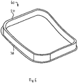
- Fig. 6 depicts a structural frame element 40 that is also obtainable by the method described before.
- the structural frame element 40 may be a window frame or door frame that is installed in a fuselage to reinforce the cut-outs.
- the structural frame element 40 is double curved.
- the invention proposes to lay up textile material members on a mandrel (10) so as to form a plurality of structural element preforms (14) that are space apart along an extended direction of the mandrel (10).
- the structural element preforms (14) form closed loops (18) and are subsequently cured to obtain annular structural elements (20).
- the annular structural elements (20) are used as basic building blocks for stiffening panel members (24) or are directly used as structural frame elements (40) reinforcing cut-outs in a fuselage for windows and/or doors.
Landscapes
- Engineering & Computer Science (AREA)
- Mechanical Engineering (AREA)
- Chemical & Material Sciences (AREA)
- Composite Materials (AREA)
- Aviation & Aerospace Engineering (AREA)
- Textile Engineering (AREA)
- Robotics (AREA)
- Manufacturing & Machinery (AREA)
- Civil Engineering (AREA)
- Structural Engineering (AREA)
- Architecture (AREA)
- Transportation (AREA)
- Moulding By Coating Moulds (AREA)
Abstract
Description
- The invention relates to a method for manufacturing a structural element for a fuselage of an aircraft. The invention relates further to specific structural parts that employ said structural element.
-
EP 3 165 448 B1 discloses a method for manufacturing an aperture surrounding frame. A single tubular braided member is cut and layed up around an inner mold. Subsequently, the tubular member is formed and cured to obtain the aperture surrounding frame. - Cut-outs in aircraft fuselages, such as for doors (be it passenger doors, cargo doors or the like) and windows, as well as the doors themselves usually have structural elements for reinforcement. The structural elements are usually manufactured separately and attached to the door, for example, by bolting. Thus, many reinforcement structures have a ring-like structure. Their manufacture is typically high-effort and therefore high cost.
- It is the object of the invention to improve the manufacture of structural elements. The object is achieved by the subject-matter of the independent claims. Preferred embodiments are subject-matter of the dependent claims.
- The invention provides a method for manufacturing a structural element for a fuselage of an aircraft, the method comprising:
- a) on a mandrel that extends in a longitudinal direction, laying up a plurality of textile material members so as to form at least one structural element preform next to each other;
- b) curing the structural element preform, so as to obtain a structural elements.
- Preferably, in step a) the textile material members are layed up on the mandrel such that a plurality of structural element preforms are spaced apart along the longitudinal direction.
- Preferably, the mandrel is a split mandrel or half-size mandrel.
- Preferably, the textile material members are layed up on a circumferential surface of the mandrel, so as to form a closed loop structural element preform. Preferably, in step b) the structural element preforms are cured to obtain an annular structural element.
- Preferably, the method comprises a step c) in which the mandrel is removed by pulling off the structural elements from the mandrel or by moving separate portions of the mandrel relative to each other.
- Preferably, in step a) the laying up is done by winding around the mandrel, automated fiber placement, automated tape layering of the textile material members.
- Preferably, the textile material members are chosen from a group consisting of textile material, fiber composite material, tows, slit tape, fiber tape, non-crimp fabric, non-woven fabric, and prepregs.
- Preferably, in step b) at least one structural element preform is layed up by laying up the textile material members on the mandrel such that the structural element preform is double-curved. Preferably, a first curvature is formed by continuously displacing the textile material members during laying up along the longitudinal axis up to a maximum displacement. Preferably, a second curvature is formed by laying up the textile material members around a circumferential surface of the mandrel.
- Preferably, the first curvature is further formed by continuously displacing the textile material members during laying up in an opposite direction along the longitudinal axis from the maximum displacement until the textile material members form a closed loop structural element preform.
- The invention provides a method for manufacturing a structural frame element for a cut-out in a fuselage, such as a window frame or a door frame, of an aircraft, the method comprising the step of performing a preferred method such that an annular structural element is formed that is adapted to be arranged to surround the cut-out in the fuselage and to be arranged in between skins of the fuselage.
- The invention provides a method for manufacturing a stiffened structural panel element of an aircraft, the method comprising the steps of:
- a) performing the preferred method such that at least one annular structural elements is produced, the annular structural element extending along an element axis and circumferentially surrounding the element axis;
- b) providing a panel member;
- c) affixing the annular structural element to the panel member so as to obtain the structural panel element.
- Preferably, in step c) the annular structural elements are affixed, so as to form a structural grid.
- Preferably, in step c) the annular structural elements are affixed, so that adjacent annular structural elements engage each other at an engagement location. Preferably, the annular structural elements are fixed to each other at the engagement locations.
- Preferably, the annular structural elements are affixed to the panel member by bonding, welding or bolting. Preferably, the annular structural elements are fixed to each other by bonding, welding or bolting.
- The invention provides a structural frame element or a stiffened structural panel element obtainable by a preferred method.
- The disclosed invention relates to the field of concepts and manufacturing of aircraft structural elements. The structural elements are preferably used in a composite substructure for cut-out (opening) reinforcement. Preferably thermoplastic matrix systems are used for the structural elements. In general, the substructures have a ring shape, meaning they circumferentially surround an axis in which the substructure extends. In other words, ring shape or annular does not imply that those parts are circular. Rather as used herein, any shape that surrounds a (central) element axis is ring-shaped or annular within the meaning of this disclosure.
- The ideas disclosed herein are applicable to structural elements that previously were produced by manufacturing skin and stiffening elements, and were assembly mainly by bolting. According to the invention fewer parts are needed, which considerably reduces the assembly effort. For cut-outs, it is possible to replace the currently different concepts, for example the deep drawn elements for the waste water panel. Furthermore, the ideas herein are able to improve the manufacture of the backup structures of panels and doors that may be used to close-off the cut-outs. In terms of weight efficiency ring-like or annular structures as envisaged herein can offer a better performance e.g. due to better following the shape of the cut-out.
- Typically there are backup structures for reinforcement of the cut-out and backup structures for a door that closes the cut-out and has a panel that is supported by another backup structure. An important element of this idea is a (vertical flange) structural element that is of annular shape. The proposed concept is attractive for repetitive ring elements with roughly the same shape. Therefore it is possible with the invention to manufacture large quantities in one-shot.
- The benefits of the proposed solution include, but are not limited to the following advantages. It should be noted that not all advantages must be realized at the same time or in the same amount.
- The methods allow a significant reduction of parts (ideally main structural elements are reduced to one or two parts). The design is made of composite material and light-weight. The manufacturing effort can be reduced by an efficient part sub-assembly for doors, cut-outs and the like, by preferably co-consolidation or local over molding of the substructure. In case of thermosetting matrix material co-infusion is also possible.
- The cut-out surround structure can be integrated directly on a panel/skin by local over molding or an autoclave process. If need be, flanges can be integrated into the reinforcement ring upfront for better integration into the pre-assembled structure in a second step (e.g. by bolting, bonding or welding. Faster processing times and less scrap can be achieved for single parts. In addition the same can be achieved for the assembled part due to higher integration. With the ideas herein, the overall lead time can be reduce, in particular with respect to assembly time. Integration can be achieved without dust (carbon dust for example) when co-consolidating. The invention allows for a high production rate. The disclosed ideas are a manufacturing/technology approach that can be applied for almost all kinds of shell/panel structures that are supporting cut-outs.
- One example are aircraft doors, such as hatches, bulk cargo doors, passenger (PAX) doors and cargo doors. Typically a bulk door contains a panel, a grid and a surrounding edge member. The edge member is a ring structure. Several edge members may be layed up on a single mandrel for a fast and easy production of a large quantity of parts at the same time.
- The layup of the material on the mandrel can be done with different processes, such as winding of tows (dry, wet etc.), automated fiber placement (AFP) slit tape, automated tape layering or manually. It is possible to use wet or dry materials (e.g. non-crimp fiber, fabric).
- Further examples of application can be window frames or door frames. To achieve the needed shape of the ring-structures a sub-sequent machining (e.g. waterjet cutting or milling) may be applied. This allows to have rings that can be used as stiffener in double curved areas. Additionally machining can be done in the needed angle and areas which are not needed can be cut away.
- The ideas disclosed herein are particularly useful for double curved panel structures, since double curved elements usually lead to high effort for manufacturing several special parts. With the solution here, each part can be manufactured without unique tooling. The single part effort is mainly caused by the major process steps which are more or less the same as if one large integrated part is manufactured. Another benefit can be a faster layup and less scrap by manufacturing multiple parts one shot on one larger tool. This concept can be transferred to all ring-shaped structural elements, such as a panel with a reinforcing substructure that is made of rings that are connected to form a grid pattern for reinforcement. An example is an (iso)-grid formed by circles, squares or the like. These ring elements can be integrated by bonding or welding (e.g. if thermoplastic resin is used).
- The ring are welded or molten together to form a larger structure. The ring elements can differ in shape, size, height, and/or their joining locations between the rings. The elements can act as load introduction (e.g. to connect beams) and allow a "dust-free" connection for assembly of later attached elements (modules) including tolerance compensation.
- The ring elements can be connected to each other by connection of their surfaces by bonding, welding or bolting. Welding has the advantage of being fast an cheap. Using bonding agent allows for a filler from the ring web to the panel to which it is affixed. Bolting is an option, if a flange is available. Circular shapes that are made of or include thermoplastic resin may be affixed to the panel by rotation friction welding.
- Possible materials for the ring elements include thermoset resin composites (bonding or co-bonding/curing), thermoplastic resin composites (welding can be done), combinations of thermosetting and thermoplastic resin, and short fiber reinforced materials in thermosetting or thermoplastic resin can be used for fillers.
- Embodiments of the invention are described in more detail with reference to the accompanying schematic drawings that are listed below
- Fig. 1
- depicts an embodiment of a method for manufacturing a stiffened structural panel element;
- Fig. 2
- depicts a variant of a stiffened structural panel element;
- Fig. 3
- depicts another variant of a stiffened structural panel element;
- Fig. 4
- depicts a joint between a structural element and a panel;
- Fig. 5
- depicts a joint between another structural element and the panel; and
- Fig. 6
- depicts an embodiment of a structural frame element.
- As depicted in
Fig. 1 , in a first step a plurality of textile material members are layed up on a mandrel 10. The mandrel 10 extends in a longitudinal direction (left-right direction inFig. 1 ). The mandrel 10 has acircumferential surface 12 that is a forming surface for the textile material members. The textile material members may be tows or slit tape that is wound around the mandrel 10 or applied to thecircumferential surface 12. - The textile material members are layed up in such a way that a plurality of structural element preforms 14 are generated. The structural element preforms 14 are spaced apart along the longitudinal direction. The structural element preforms 14 can be double curved.
- A first curvature is formed by continuously displacing the textile material members along the longitudinal direction up to a maximum displacement d. In other words, the textile material members are progressively arranged outside of a
cross-sectional plane 16 through the mandrel 10 that is orthogonal to the longitudinal direction until a desired maximum is reached. After that the textile material members are progressively brought back so that as a result the structural element preform 14 forms aclosed loop 18. - A second curvature is formed by the
circumferential surface 12 of the mandrel 10. - In a second step, the structural element preforms 14 are subsequently cured in order to obtain annular
structural elements 20 that are suitable for reinforcing. The annularstructural elements 20 extend along anelement axis 22 which is also called height h. The annularstructural elements 20 surround theelement axis 22 in a circumferential direction. - Finally, the
structural elements 20 are affixed to apanel member 24 such that thestructural elements 20 form astructural grid 26. Thestructural elements 20 therefore are able to act as stiffening elements for thepanel member 24. Thestructural elements 20 are arranged so that they engage each other atcertain engagement locations 28. Thestructural elements 20 are fixed to each other at theseengagement locations 28. As a result, a stiffenedstructural panel element 30 is obtained that may be used for manufacturing a fuselage or various doors of an aircraft. - As depicted in
Fig. 2 , a variant of the stiffenedstructural panel element 30 comprisesstructural elements 20 having substantially rectangular cross-section. Other configurations, including double curved configurations are possible. - As depicted in
Fig. 3 , a variant of the stiffenedstructural panel element 30 may havestructural elements 20 that have different height h. A largerstructural element 32 may serve as a mount point for struts and other elements that are typically used in a fuselage. The largerstructural element 32 has also a larger height H compared to thestructural elements 20. - As depicted in
Fig. 4 , thestructural element 20 can be affixed to thepanel member 24 by an adhesive that forms afiller 34. - As depicted in
Fig. 5 , thestructural element 20 may be manufactured with aflange portion 36. Adjacentstructural elements 20 can be affixed to thepanel member 24 by introducing adhesive into a cavity 38 defined between the adjacentstructural elements 20 and thepanel member 24. It is also possible to bolt theflange portions 36 to thepanel member 24. -
Fig. 6 depicts astructural frame element 40 that is also obtainable by the method described before. Thestructural frame element 40 may be a window frame or door frame that is installed in a fuselage to reinforce the cut-outs. Thestructural frame element 40 is double curved. - In order to improve the manufacture of structural elements (20), the invention proposes to lay up textile material members on a mandrel (10) so as to form a plurality of structural element preforms (14) that are space apart along an extended direction of the mandrel (10). The structural element preforms (14) form closed loops (18) and are subsequently cured to obtain annular structural elements (20). The annular structural elements (20) are used as basic building blocks for stiffening panel members (24) or are directly used as structural frame elements (40) reinforcing cut-outs in a fuselage for windows and/or doors.
-
- 10
- mandrel
- 12
- circumferential surface
- 14
- structural element preform
- 16
- cross-sectional plane
- 18
- closed loop
- 20
- annular structural element
- 22
- element axis
- 24
- panel member
- 26
- structural grid
- 28
- engagement location
- 30
- stiffened structural panel element
- 32
- larger structural element
- 34
- filler
- 36
- flange portion
- 38
- cavity
- 40
- structural frame element
- d
- maximum displacement
- h
- height
- H
- larger height
Claims (15)
- A method for manufacturing a structural element (20) for a fuselage of an aircraft, the method comprising:a) on a mandrel (10) that extends in a longitudinal direction, laying up a plurality of textile material members so as to form at least one structural element preform (14) next to each other;b) curing the structural element preform (14), so as to obtain a structural elements (20).
- The method according to claim 1, wherein in step a) the textile material members are layed up on the mandrel (10) such that a plurality of structural element preforms (14) are spaced apart along the longitudinal direction.
- The method according to any of the preceding claims, wherein the mandrel (10) is a split mandrel or half-size mandrel.
- The method according to any of the preceding claims, wherein the textile material members are layed up on a circumferential surface (12) of the mandrel (10), so as to form a closed loop (18) structural element preform (14), and in step b) the structural element preforms (14) are cured to obtain an annular structural element (20).
- The method according to any of the preceding claims, wherein in a step c) the mandrel (10) is removed by pulling off the structural elements (20) from the mandrel (10) or by moving separate portions of the mandrel (10) relative to each other.
- The method according to any of the preceding claims, wherein in step a) the laying up is done by winding around the mandrel (10), automated fiber placement, automated tape layering of the textile material members.
- The method according to any of the preceding claims, wherein the textile material members are chosen from a group consisting of textile material, fiber composite material, tows, slit tape, fiber tape, non-crimp fabric, non-woven fabric, and prepregs.
- The method according to any of the preceding claims, wherein in step b) at least one structural element preform (14) is layed up by laying up the textile material members on the mandrel (10) such that the structural element preform (14) is double curved, wherein a first curvature is formed by continuously displacing the textile material members during laying up along the longitudinal axis up to a maximum displacement (d), and a second curvature is formed by laying up the textile material members around a circumferential surface (12) of the mandrel (10).
- The method according to claim 8, wherein the first curvature is further formed by continuously displacing the textile material members during laying up in an opposite direction along the longitudinal axis from the maximum displacement (d) until the textile material members form a closed loop (18) structural element preform (14).
- A method for manufacturing a structural frame element (40) for a cut-out in a fuselage of an aircraft, the method comprising the step of performing a method according to any of the claims 4 to 9 such that an annular structural element (20) is formed that is adapted to be arranged to surround the cut-out in the fuselage and to be arranged on a skin or in between skins of the fuselage.
- A method for manufacturing a stiffened structural panel element (30) of an aircraft, the method comprising the steps of:a) performing the method according to any of the claims 4 to 9 such that at least one annular structural elements (20) is produced, the annular structural element (20) extending along an element axis (22) and circumferentially surrounding the element axis (22);b) providing a panel member (24);c) affixing the annular structural element (20) to the panel member (24) so as to obtain the structural panel element (30).
- The method according to claim 11, wherein in step c) the annular structural elements (20) are affixed, so as to form a structural grid (26).
- The method according to any of the claims 11 or 12, wherein in step c) the annular structural elements (20) are affixed, so that adjacent annular structural elements (20) engage each other at an engagement location (28), and the annular structural elements (20) are fixed to each other at the engagement locations (28).
- The method according to claim 13, wherein the annular structural elements (20) are affixed to the panel member (24) by bonding, welding or bolting, and/or the annular structural elements (20) are fixed to each other by bonding, welding or bolting.
- A structural frame element (40) or a stiffened structural panel element (30) obtainable by a method according to any of the claims 10 to 15.
Priority Applications (2)
| Application Number | Priority Date | Filing Date | Title |
|---|---|---|---|
| EP21187300.5A EP4122683A1 (en) | 2021-07-22 | 2021-07-22 | A method for manufacturing a structural element for a fuselage of an aircraft |
| US17/868,162 US12448108B2 (en) | 2021-07-22 | 2022-07-19 | Method for manufacturing a structural element for a fuselage of an aircraft |
Applications Claiming Priority (1)
| Application Number | Priority Date | Filing Date | Title |
|---|---|---|---|
| EP21187300.5A EP4122683A1 (en) | 2021-07-22 | 2021-07-22 | A method for manufacturing a structural element for a fuselage of an aircraft |
Publications (1)
| Publication Number | Publication Date |
|---|---|
| EP4122683A1 true EP4122683A1 (en) | 2023-01-25 |
Family
ID=77042760
Family Applications (1)
| Application Number | Title | Priority Date | Filing Date |
|---|---|---|---|
| EP21187300.5A Pending EP4122683A1 (en) | 2021-07-22 | 2021-07-22 | A method for manufacturing a structural element for a fuselage of an aircraft |
Country Status (2)
| Country | Link |
|---|---|
| US (1) | US12448108B2 (en) |
| EP (1) | EP4122683A1 (en) |
Citations (7)
| Publication number | Priority date | Publication date | Assignee | Title |
|---|---|---|---|---|
| CA2628261A1 (en) * | 2005-10-31 | 2007-05-10 | The Boeing Company | Single piece fuselage barrel |
| EP2772344A1 (en) * | 2013-03-01 | 2014-09-03 | Bell Helicopter Textron Inc. | System and method of manufacturing composite core |
| KR101489292B1 (en) * | 2014-10-20 | 2015-02-04 | 재단법인 중소조선연구원 | apparatus for manufacturing composite leaf spring |
| US20180036959A1 (en) * | 2016-08-02 | 2018-02-08 | The Boeing Company | Tubular Structure and a Method of Manufacturing Thereof |
| EP3165448B1 (en) | 2015-11-05 | 2020-01-01 | Airbus Operations, S.L. | Method for manufacturing an aperture surrounding frame for an aircraft fuselage, and frame |
| US20200139643A1 (en) * | 2018-11-02 | 2020-05-07 | The Boeing Company | Composite structures constructed of wound tubular braiding |
| US20210206135A1 (en) * | 2020-01-02 | 2021-07-08 | The Boeing Company | Composite structural panels and methods of forming thereof |
Family Cites Families (1)
| Publication number | Priority date | Publication date | Assignee | Title |
|---|---|---|---|---|
| US11345061B2 (en) * | 2019-04-24 | 2022-05-31 | Arris Composites Inc. | Method and system for batch preforming of fiber bundles |
-
2021
- 2021-07-22 EP EP21187300.5A patent/EP4122683A1/en active Pending
-
2022
- 2022-07-19 US US17/868,162 patent/US12448108B2/en active Active
Patent Citations (7)
| Publication number | Priority date | Publication date | Assignee | Title |
|---|---|---|---|---|
| CA2628261A1 (en) * | 2005-10-31 | 2007-05-10 | The Boeing Company | Single piece fuselage barrel |
| EP2772344A1 (en) * | 2013-03-01 | 2014-09-03 | Bell Helicopter Textron Inc. | System and method of manufacturing composite core |
| KR101489292B1 (en) * | 2014-10-20 | 2015-02-04 | 재단법인 중소조선연구원 | apparatus for manufacturing composite leaf spring |
| EP3165448B1 (en) | 2015-11-05 | 2020-01-01 | Airbus Operations, S.L. | Method for manufacturing an aperture surrounding frame for an aircraft fuselage, and frame |
| US20180036959A1 (en) * | 2016-08-02 | 2018-02-08 | The Boeing Company | Tubular Structure and a Method of Manufacturing Thereof |
| US20200139643A1 (en) * | 2018-11-02 | 2020-05-07 | The Boeing Company | Composite structures constructed of wound tubular braiding |
| US20210206135A1 (en) * | 2020-01-02 | 2021-07-08 | The Boeing Company | Composite structural panels and methods of forming thereof |
Also Published As
| Publication number | Publication date |
|---|---|
| US20230026741A1 (en) | 2023-01-26 |
| US12448108B2 (en) | 2025-10-21 |
Similar Documents
| Publication | Publication Date | Title |
|---|---|---|
| US6632502B1 (en) | Method for fabricating an advanced composite aerostructure article having an integral co-cured fly away hollow mandrel | |
| EP2301840B1 (en) | Integrated aircraft structure in composite material | |
| US8398910B2 (en) | Method for manufacturing a fibre-composite component, fibre-composite component and fibre-composite fuselage component of an aircraft | |
| EP1893478B1 (en) | Reinforcement beam as well as method and fiber laminate for manufacturing the reinforcement beam | |
| EP0749825B1 (en) | Fiber-reinforced composite structural element and method of manufacturing the same | |
| US20100038030A1 (en) | Advanced composite aerostructure article having a braided co-cured fly away hollow mandrel and method for fabrication | |
| US6510961B1 (en) | Integrally-reinforced braided tubular structure and method of producing the same | |
| KR101737669B1 (en) | Multi-box spar and skin | |
| US9796142B2 (en) | Method for manufacturing a part made of composite material for an aircraft structure by pultrusion and cocuring | |
| CN105539858A (en) | Engine nacelle, method for assembling barrel body structure, and method for constructing inner barrel structure of engine nacelle | |
| EP3483057B1 (en) | Reinforcing arrangement for an opening in an aircraft structure | |
| US9034453B2 (en) | Reinforced aircraft fuselage panel and method of manufacture | |
| EP1800842A1 (en) | A method of manufacturing an elongate structural element configured for stiffening a shell structure, and a method for manufacturing a rigid shell structure integrated with at least one elongate stiffening element | |
| EP3501971A1 (en) | Aircraft rear fuselage section and manufacturing method thereof | |
| EP2295228B1 (en) | Method of manufacturing a fuselage frame of composite material | |
| US12448108B2 (en) | Method for manufacturing a structural element for a fuselage of an aircraft | |
| EP1899149B1 (en) | Process for producing a substantially shell-shaped component | |
| US11273895B2 (en) | Planar pressure bulkhead for an air- or spacecraft and air- or spacecraft | |
| EP3628583B1 (en) | Thermoplastic multi-grid overmolded/co-consolidated aircraft fuselage structure | |
| RU77842U1 (en) | BEAM FLOOR BEAM FROM POLYMERIC COMPOSITE MATERIALS | |
| EP3248774A1 (en) | Fireproof polymer matrix composite structure |
Legal Events
| Date | Code | Title | Description |
|---|---|---|---|
| PUAI | Public reference made under article 153(3) epc to a published international application that has entered the european phase |
Free format text: ORIGINAL CODE: 0009012 |
|
| STAA | Information on the status of an ep patent application or granted ep patent |
Free format text: STATUS: THE APPLICATION HAS BEEN PUBLISHED |
|
| AK | Designated contracting states |
Kind code of ref document: A1 Designated state(s): AL AT BE BG CH CY CZ DE DK EE ES FI FR GB GR HR HU IE IS IT LI LT LU LV MC MK MT NL NO PL PT RO RS SE SI SK SM TR |
|
| STAA | Information on the status of an ep patent application or granted ep patent |
Free format text: STATUS: REQUEST FOR EXAMINATION WAS MADE |
|
| 17P | Request for examination filed |
Effective date: 20230725 |
|
| RBV | Designated contracting states (corrected) |
Designated state(s): AL AT BE BG CH CY CZ DE DK EE ES FI FR GB GR HR HU IE IS IT LI LT LU LV MC MK MT NL NO PL PT RO RS SE SI SK SM TR |
|
| STAA | Information on the status of an ep patent application or granted ep patent |
Free format text: STATUS: EXAMINATION IS IN PROGRESS |
|
| 17Q | First examination report despatched |
Effective date: 20250617 |