EP4122681A1 - Method of permanently joining composite parts made from thermoplastic material, arrangement of composite parts, and aircraft - Google Patents
Method of permanently joining composite parts made from thermoplastic material, arrangement of composite parts, and aircraft Download PDFInfo
- Publication number
- EP4122681A1 EP4122681A1 EP21186412.9A EP21186412A EP4122681A1 EP 4122681 A1 EP4122681 A1 EP 4122681A1 EP 21186412 A EP21186412 A EP 21186412A EP 4122681 A1 EP4122681 A1 EP 4122681A1
- Authority
- EP
- European Patent Office
- Prior art keywords
- composite
- orifice
- composite part
- thermoplastic material
- parts
- Prior art date
- Legal status (The legal status is an assumption and is not a legal conclusion. Google has not performed a legal analysis and makes no representation as to the accuracy of the status listed.)
- Pending
Links
Images



Classifications
-
- B—PERFORMING OPERATIONS; TRANSPORTING
- B29—WORKING OF PLASTICS; WORKING OF SUBSTANCES IN A PLASTIC STATE IN GENERAL
- B29C—SHAPING OR JOINING OF PLASTICS; SHAPING OF MATERIAL IN A PLASTIC STATE, NOT OTHERWISE PROVIDED FOR; AFTER-TREATMENT OF THE SHAPED PRODUCTS, e.g. REPAIRING
- B29C66/00—General aspects of processes or apparatus for joining preformed parts
- B29C66/70—General aspects of processes or apparatus for joining preformed parts characterised by the composition, physical properties or the structure of the material of the parts to be joined; Joining with non-plastics material
- B29C66/72—General aspects of processes or apparatus for joining preformed parts characterised by the composition, physical properties or the structure of the material of the parts to be joined; Joining with non-plastics material characterised by the structure of the material of the parts to be joined
- B29C66/721—Fibre-reinforced materials
-
- B—PERFORMING OPERATIONS; TRANSPORTING
- B29—WORKING OF PLASTICS; WORKING OF SUBSTANCES IN A PLASTIC STATE IN GENERAL
- B29C—SHAPING OR JOINING OF PLASTICS; SHAPING OF MATERIAL IN A PLASTIC STATE, NOT OTHERWISE PROVIDED FOR; AFTER-TREATMENT OF THE SHAPED PRODUCTS, e.g. REPAIRING
- B29C65/00—Joining or sealing of preformed parts, e.g. welding of plastics materials; Apparatus therefor
- B29C65/02—Joining or sealing of preformed parts, e.g. welding of plastics materials; Apparatus therefor by heating, with or without pressure
- B29C65/40—Applying molten plastics, e.g. hot melt
- B29C65/42—Applying molten plastics, e.g. hot melt between pre-assembled parts
-
- B—PERFORMING OPERATIONS; TRANSPORTING
- B29—WORKING OF PLASTICS; WORKING OF SUBSTANCES IN A PLASTIC STATE IN GENERAL
- B29C—SHAPING OR JOINING OF PLASTICS; SHAPING OF MATERIAL IN A PLASTIC STATE, NOT OTHERWISE PROVIDED FOR; AFTER-TREATMENT OF THE SHAPED PRODUCTS, e.g. REPAIRING
- B29C65/00—Joining or sealing of preformed parts, e.g. welding of plastics materials; Apparatus therefor
- B29C65/56—Joining or sealing of preformed parts, e.g. welding of plastics materials; Apparatus therefor using mechanical means or mechanical connections, e.g. form-fits
- B29C65/60—Riveting or staking
- B29C65/601—Riveting or staking using extra riveting elements, i.e. the rivets being non-integral with the parts to be joined
- B29C65/605—Riveting or staking using extra riveting elements, i.e. the rivets being non-integral with the parts to be joined the rivets being molded in place, e.g. by injection
-
- B—PERFORMING OPERATIONS; TRANSPORTING
- B29—WORKING OF PLASTICS; WORKING OF SUBSTANCES IN A PLASTIC STATE IN GENERAL
- B29C—SHAPING OR JOINING OF PLASTICS; SHAPING OF MATERIAL IN A PLASTIC STATE, NOT OTHERWISE PROVIDED FOR; AFTER-TREATMENT OF THE SHAPED PRODUCTS, e.g. REPAIRING
- B29C66/00—General aspects of processes or apparatus for joining preformed parts
- B29C66/01—General aspects dealing with the joint area or with the area to be joined
- B29C66/05—Particular design of joint configurations
- B29C66/10—Particular design of joint configurations particular design of the joint cross-sections
- B29C66/11—Joint cross-sections comprising a single joint-segment, i.e. one of the parts to be joined comprising a single joint-segment in the joint cross-section
- B29C66/112—Single lapped joints
-
- B—PERFORMING OPERATIONS; TRANSPORTING
- B29—WORKING OF PLASTICS; WORKING OF SUBSTANCES IN A PLASTIC STATE IN GENERAL
- B29C—SHAPING OR JOINING OF PLASTICS; SHAPING OF MATERIAL IN A PLASTIC STATE, NOT OTHERWISE PROVIDED FOR; AFTER-TREATMENT OF THE SHAPED PRODUCTS, e.g. REPAIRING
- B29C66/00—General aspects of processes or apparatus for joining preformed parts
- B29C66/01—General aspects dealing with the joint area or with the area to be joined
- B29C66/05—Particular design of joint configurations
- B29C66/10—Particular design of joint configurations particular design of the joint cross-sections
- B29C66/11—Joint cross-sections comprising a single joint-segment, i.e. one of the parts to be joined comprising a single joint-segment in the joint cross-section
- B29C66/112—Single lapped joints
- B29C66/1122—Single lap to lap joints, i.e. overlap joints
-
- B—PERFORMING OPERATIONS; TRANSPORTING
- B29—WORKING OF PLASTICS; WORKING OF SUBSTANCES IN A PLASTIC STATE IN GENERAL
- B29C—SHAPING OR JOINING OF PLASTICS; SHAPING OF MATERIAL IN A PLASTIC STATE, NOT OTHERWISE PROVIDED FOR; AFTER-TREATMENT OF THE SHAPED PRODUCTS, e.g. REPAIRING
- B29C66/00—General aspects of processes or apparatus for joining preformed parts
- B29C66/01—General aspects dealing with the joint area or with the area to be joined
- B29C66/05—Particular design of joint configurations
- B29C66/10—Particular design of joint configurations particular design of the joint cross-sections
- B29C66/13—Single flanged joints; Fin-type joints; Single hem joints; Edge joints; Interpenetrating fingered joints; Other specific particular designs of joint cross-sections not provided for in groups B29C66/11 - B29C66/12
- B29C66/131—Single flanged joints, i.e. one of the parts to be joined being rigid and flanged in the joint area
-
- B—PERFORMING OPERATIONS; TRANSPORTING
- B29—WORKING OF PLASTICS; WORKING OF SUBSTANCES IN A PLASTIC STATE IN GENERAL
- B29C—SHAPING OR JOINING OF PLASTICS; SHAPING OF MATERIAL IN A PLASTIC STATE, NOT OTHERWISE PROVIDED FOR; AFTER-TREATMENT OF THE SHAPED PRODUCTS, e.g. REPAIRING
- B29C66/00—General aspects of processes or apparatus for joining preformed parts
- B29C66/01—General aspects dealing with the joint area or with the area to be joined
- B29C66/05—Particular design of joint configurations
- B29C66/20—Particular design of joint configurations particular design of the joint lines, e.g. of the weld lines
- B29C66/21—Particular design of joint configurations particular design of the joint lines, e.g. of the weld lines said joint lines being formed by a single dot or dash or by several dots or dashes, i.e. spot joining or spot welding
-
- B—PERFORMING OPERATIONS; TRANSPORTING
- B29—WORKING OF PLASTICS; WORKING OF SUBSTANCES IN A PLASTIC STATE IN GENERAL
- B29C—SHAPING OR JOINING OF PLASTICS; SHAPING OF MATERIAL IN A PLASTIC STATE, NOT OTHERWISE PROVIDED FOR; AFTER-TREATMENT OF THE SHAPED PRODUCTS, e.g. REPAIRING
- B29C66/00—General aspects of processes or apparatus for joining preformed parts
- B29C66/40—General aspects of joining substantially flat articles, e.g. plates, sheets or web-like materials; Making flat seams in tubular or hollow articles; Joining single elements to substantially flat surfaces
- B29C66/41—Joining substantially flat articles ; Making flat seams in tubular or hollow articles
- B29C66/43—Joining a relatively small portion of the surface of said articles
-
- B—PERFORMING OPERATIONS; TRANSPORTING
- B29—WORKING OF PLASTICS; WORKING OF SUBSTANCES IN A PLASTIC STATE IN GENERAL
- B29C—SHAPING OR JOINING OF PLASTICS; SHAPING OF MATERIAL IN A PLASTIC STATE, NOT OTHERWISE PROVIDED FOR; AFTER-TREATMENT OF THE SHAPED PRODUCTS, e.g. REPAIRING
- B29C66/00—General aspects of processes or apparatus for joining preformed parts
- B29C66/50—General aspects of joining tubular articles; General aspects of joining long products, i.e. bars or profiled elements; General aspects of joining single elements to tubular articles, hollow articles or bars; General aspects of joining several hollow-preforms to form hollow or tubular articles
- B29C66/51—Joining tubular articles, profiled elements or bars; Joining single elements to tubular articles, hollow articles or bars; Joining several hollow-preforms to form hollow or tubular articles
- B29C66/52—Joining tubular articles, bars or profiled elements
- B29C66/524—Joining profiled elements
-
- B—PERFORMING OPERATIONS; TRANSPORTING
- B29—WORKING OF PLASTICS; WORKING OF SUBSTANCES IN A PLASTIC STATE IN GENERAL
- B29C—SHAPING OR JOINING OF PLASTICS; SHAPING OF MATERIAL IN A PLASTIC STATE, NOT OTHERWISE PROVIDED FOR; AFTER-TREATMENT OF THE SHAPED PRODUCTS, e.g. REPAIRING
- B29C66/00—General aspects of processes or apparatus for joining preformed parts
- B29C66/50—General aspects of joining tubular articles; General aspects of joining long products, i.e. bars or profiled elements; General aspects of joining single elements to tubular articles, hollow articles or bars; General aspects of joining several hollow-preforms to form hollow or tubular articles
- B29C66/51—Joining tubular articles, profiled elements or bars; Joining single elements to tubular articles, hollow articles or bars; Joining several hollow-preforms to form hollow or tubular articles
- B29C66/53—Joining single elements to tubular articles, hollow articles or bars
- B29C66/532—Joining single elements to the wall of tubular articles, hollow articles or bars
-
- B—PERFORMING OPERATIONS; TRANSPORTING
- B29—WORKING OF PLASTICS; WORKING OF SUBSTANCES IN A PLASTIC STATE IN GENERAL
- B29C—SHAPING OR JOINING OF PLASTICS; SHAPING OF MATERIAL IN A PLASTIC STATE, NOT OTHERWISE PROVIDED FOR; AFTER-TREATMENT OF THE SHAPED PRODUCTS, e.g. REPAIRING
- B29C66/00—General aspects of processes or apparatus for joining preformed parts
- B29C66/50—General aspects of joining tubular articles; General aspects of joining long products, i.e. bars or profiled elements; General aspects of joining single elements to tubular articles, hollow articles or bars; General aspects of joining several hollow-preforms to form hollow or tubular articles
- B29C66/61—Joining from or joining on the inside
-
- B—PERFORMING OPERATIONS; TRANSPORTING
- B29—WORKING OF PLASTICS; WORKING OF SUBSTANCES IN A PLASTIC STATE IN GENERAL
- B29C—SHAPING OR JOINING OF PLASTICS; SHAPING OF MATERIAL IN A PLASTIC STATE, NOT OTHERWISE PROVIDED FOR; AFTER-TREATMENT OF THE SHAPED PRODUCTS, e.g. REPAIRING
- B29C66/00—General aspects of processes or apparatus for joining preformed parts
- B29C66/70—General aspects of processes or apparatus for joining preformed parts characterised by the composition, physical properties or the structure of the material of the parts to be joined; Joining with non-plastics material
- B29C66/73—General aspects of processes or apparatus for joining preformed parts characterised by the composition, physical properties or the structure of the material of the parts to be joined; Joining with non-plastics material characterised by the intensive physical properties of the material of the parts to be joined, by the optical properties of the material of the parts to be joined, by the extensive physical properties of the parts to be joined, by the state of the material of the parts to be joined or by the material of the parts to be joined being a thermoplastic or a thermoset
- B29C66/739—General aspects of processes or apparatus for joining preformed parts characterised by the composition, physical properties or the structure of the material of the parts to be joined; Joining with non-plastics material characterised by the intensive physical properties of the material of the parts to be joined, by the optical properties of the material of the parts to be joined, by the extensive physical properties of the parts to be joined, by the state of the material of the parts to be joined or by the material of the parts to be joined being a thermoplastic or a thermoset characterised by the material of the parts to be joined being a thermoplastic or a thermoset
- B29C66/7392—General aspects of processes or apparatus for joining preformed parts characterised by the composition, physical properties or the structure of the material of the parts to be joined; Joining with non-plastics material characterised by the intensive physical properties of the material of the parts to be joined, by the optical properties of the material of the parts to be joined, by the extensive physical properties of the parts to be joined, by the state of the material of the parts to be joined or by the material of the parts to be joined being a thermoplastic or a thermoset characterised by the material of the parts to be joined being a thermoplastic or a thermoset characterised by the material of at least one of the parts being a thermoplastic
- B29C66/73921—General aspects of processes or apparatus for joining preformed parts characterised by the composition, physical properties or the structure of the material of the parts to be joined; Joining with non-plastics material characterised by the intensive physical properties of the material of the parts to be joined, by the optical properties of the material of the parts to be joined, by the extensive physical properties of the parts to be joined, by the state of the material of the parts to be joined or by the material of the parts to be joined being a thermoplastic or a thermoset characterised by the material of the parts to be joined being a thermoplastic or a thermoset characterised by the material of at least one of the parts being a thermoplastic characterised by the materials of both parts being thermoplastics
-
- B—PERFORMING OPERATIONS; TRANSPORTING
- B64—AIRCRAFT; AVIATION; COSMONAUTICS
- B64C—AEROPLANES; HELICOPTERS
- B64C1/00—Fuselages; Constructional features common to fuselages, wings, stabilising surfaces or the like
- B64C1/06—Frames; Stringers; Longerons ; Fuselage sections
- B64C1/12—Construction or attachment of skin panels
-
- B—PERFORMING OPERATIONS; TRANSPORTING
- B29—WORKING OF PLASTICS; WORKING OF SUBSTANCES IN A PLASTIC STATE IN GENERAL
- B29C—SHAPING OR JOINING OF PLASTICS; SHAPING OF MATERIAL IN A PLASTIC STATE, NOT OTHERWISE PROVIDED FOR; AFTER-TREATMENT OF THE SHAPED PRODUCTS, e.g. REPAIRING
- B29C66/00—General aspects of processes or apparatus for joining preformed parts
- B29C66/70—General aspects of processes or apparatus for joining preformed parts characterised by the composition, physical properties or the structure of the material of the parts to be joined; Joining with non-plastics material
- B29C66/72—General aspects of processes or apparatus for joining preformed parts characterised by the composition, physical properties or the structure of the material of the parts to be joined; Joining with non-plastics material characterised by the structure of the material of the parts to be joined
- B29C66/721—Fibre-reinforced materials
- B29C66/7212—Fibre-reinforced materials characterised by the composition of the fibres
-
- B—PERFORMING OPERATIONS; TRANSPORTING
- B29—WORKING OF PLASTICS; WORKING OF SUBSTANCES IN A PLASTIC STATE IN GENERAL
- B29K—INDEXING SCHEME ASSOCIATED WITH SUBCLASSES B29B, B29C OR B29D, RELATING TO MOULDING MATERIALS OR TO MATERIALS FOR MOULDS, REINFORCEMENTS, FILLERS OR PREFORMED PARTS, e.g. INSERTS
- B29K2101/00—Use of unspecified macromolecular compounds as moulding material
- B29K2101/12—Thermoplastic materials
-
- B—PERFORMING OPERATIONS; TRANSPORTING
- B29—WORKING OF PLASTICS; WORKING OF SUBSTANCES IN A PLASTIC STATE IN GENERAL
- B29L—INDEXING SCHEME ASSOCIATED WITH SUBCLASS B29C, RELATING TO PARTICULAR ARTICLES
- B29L2031/00—Other particular articles
- B29L2031/30—Vehicles, e.g. ships or aircraft, or body parts thereof
- B29L2031/3076—Aircrafts
- B29L2031/3082—Fuselages
Definitions
- the invention relates to a method of permanently joining composite parts made from thermoplastic material, an arrangement of composite parts made from thermoplastic material and an aircraft comprising an arrangement of composite parts made from thermoplastic material.
- composite parts In modern aircrafts, the use of composite parts is important to decrease the weight of the aircraft and thus to reduce the energy consumption during flight. During production, composite parts need to be permanently joined together in order to create aircraft components of larger dimensions or to increase their strength.
- thermoplastic composite parts are usually permanent joined by mechanical fasteners like e.g. rivets.
- Alternative joining techniques are ultrasonic welding and resistance welding.
- these welding technologies are not mature to weld carbon fiber reinforced thermoplastics. Further, welding tests with ultrasonic and resistance welding do not achieve the expected quality.
- thermoplastic composites By a fast process resulting in joined parts of high quality, and to improve the productivity.
- the invention provides a method of permanently joining composite parts made from thermoplastic material, comprising the steps:
- a portion of the contact area is formed at the inner wall of the orifice within the first composite part and at the bottom of the orifice formed by the surface of the second composite part in the area of the orifice.
- a portion of the contact area is formed to protrude over a portion of the first composite part on its side opposite the second composite part.
- the portion of the contact area protruding over the first composite part on each side of the orifice has at least half of the width of the contact area at the bottom of the orifice.
- the orifice is formed as an elongated hole.
- the first and the second composite part are clamped together after the step of positioning both parts.
- At least one of the composite parts is formed as a profile element.
- the heated and melted thermoplastic material is simultaneously injected in a plurality of orifices provided in at least one of the composite parts to permanently join the composite parts.
- an arrangement of composite parts made from thermoplastic material comprising a first composite part and a second composite part, both made from thermoplastic material and permanently joined together, wherein an orifice containing solidified thermoplastic material is provided in at least one of the composite parts and is contacting the first and the second composite part in a contact area thereof, whereby surfaces of the first and the second composite part in that contact area are melt together by the solidified thermoplastic material in the orifice and in the contact area.
- one of the composite parts is a skin element and the other composite part is a profile element.
- the profile element is a stringer.
- the arrangement is produced by the method according to the invention.
- an aircraft which comprises an arrangement of composite parts according to the invention.
- the invention achieves the advantages of a technology to join parts made from thermoplastic composites which can be carried out in a fast and relatively simple manner.
- Thermoplastic melted material is injected or applied locally onto parts to be joined.
- the technology to get thermoplastic into melt condition is available, e.g. heat guns can be used.
- a fast process is achieved, since the parts are joined after a few seconds when the thermoplastic material temperature is below the melting temperature. Welding of long parts as e.g. stringers is possible, in particular by use of multiple injection spots, to improve productivity.
- the invention provides a new welding concept applicable for thermoplastic composites.
- the invention uses the idea that melted thermoplastic material is injected locally through the orifice of one part.
- the second part has for example no orifice.
- the inject material can be only thermoplastic or thermoplastic mixed with fibers like e.g. carbon short fibers, nano-materials, etc.
- the injected material can e.g. be pure thermoplastic material, and it can e.g. also be a thermoplastic composite material.
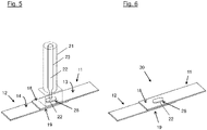
- Figs. 1 to 6 show two parts 11, 12 made from thermoplastic composites during the process of being joined according to a preferred example.
- both composite parts 11, 12, are formed as panels in this example, each having a top side 13, 14 and a bottom side 15, 16.
- an orifice 17 is provided, which is formed as a through hole extending through the first composite part 11.
- the orifice 17 is formed as an elongated hole or oval opening.
- Figure 2 shows the next step of the injection welding process.
- the first part 11 and the second part 12 are positioned in a way that a portion 18 of the first composite part surrounding the orifice 17 is adjacent to a portion 19 of the second composite part 12, both portions 18, 19 contacting each other at the underside 15 of the first composite part 11 and the upper side 14 of the second composite part 12.
- the orifice 17 forms an open container, which is closed at its bottom by the upper side 14 of the second composite part 12.
- both composite parts 11, 12 are clamped by a clamping tool 21 depicted in dotted lines, the clamping tool 21 being positioned on first composite part 11 directly in front of orifice 17.
- FIG 4 shows a next step, in which melted thermoplastic material 22 provided by an injection device 23 is injected or filled into orifice 17, which forms an injection spot 24 and which is provided in the first composite part 11. Since orifice 17 is closed at its bottom by the upper side 14 of second composite part 12, the melted thermoplastic material fills the orifice 17. Injection device 23 is formed within clamping tool 21, thereby ensuring high quality of the welding point and a faster process.
- the heated and melted thermoplastic material is injected locally through the orifice 17 of first part 11 to second part 12, which does not provide an orifice at this location.
- the hot melted thermoplastic material 22 fills the orifice 17 and gets in contact with the first composite part 11 and with the second composite part 12.
- the melted thermoplastic material 22 contacts the upper side 14 of second part 12, which forms the bottom of the orifice 17, as well as the inner wall of the opening formed by orifice 17 within first part 11.
- the melted material also covers a part of the upper surface 13 of first part 11 and forms an overhang of thermoplastic material 22 around the edge of orifice 17.
- Figure 5 shows the end of the injection step in which the injection of thermoplastic material 22 is completed.
- the thermoplastic material 22 completely fills orifice 17 and overlaps an edge portion surrounding orifice 17 at the upper side 13 of first part 12.
- a portion of the thermoplastic material 17 filled into orifice 17 also covers a portion of the upper side 17 of first part 11.
- thermoplastic material 17 After the injection, the melted thermoplastic material 17 cools down below its melting temperature, whereby the thermoplastic material 22 solidifies, thereby forming a clasp or plug 28 similar to a rivet, which is welded into the thermoplastic materials of the parts 11, 12.
- Figure 6 shows a view of both parts 11, 12 after the welding process has been completed.
- the injected and solidified thermoplastic material permanently joins both parts 11, 12 to form an arrangement 30 of two parts welded to each other
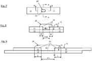
- Figure 7 depicts a top view of both parts 11, 12 joined to each other by thermoplastic welding as described above and shown in figure 6 .
- the thermoplastic material 22 has been solidified to form plug 28. It fills and also covers orifice 17 which is not visible in this figure.
- Figure 8 shows scaled section A - A as indicated in figure 7
- figure 9 shows scaled section B - B as indicated in figure 7
- the injected hot thermoplastic material 22 forms within portions of upper surfaces 13 and 14 of first and second parts 11, 12 a contact area 25. That contact area 25 shown as a dashed line melts during the injection of the hot melted thermoplastic material 22, and thus connects both thermoplastic composite parts 11, 12.
- the injected hot thermoplastic material 22 mutually with the thermoplastic materials of the parts 11, 12 in that contact area. After cooling down and solidification of the thermoplastic materials both parts 11, 12 are welded to each other
- the width W of contact area 25 formed at the upper surface 14 of second part 12 is twice the width of the contact area 25 formed in upper surface 13 of first part 11 on both sides of orifice 17 filled and covered by thermoplastic material 22.
- the first composite part 11 made from thermoplastic material is configured as an L-shape profile forming a stringer.
- the second composite part 12 made from thermoplastic material is configured as a relatively thin panel forming a skin element which shall be joined to the profile element 11 by injection welding as described above.
- a portion 26 of profile element 11 is provided with a plurality of orifices 17 forming multiple injection spots 24.
- Profile element 11 is positioned on the upper side 14 of skin element 12. Both composite parts 11, 12 are positioned in a way that portion 26 is contacting an area of the skin element 12.
- Figure 11 shows the injection of melted thermoplastic material 22 through the plurality of orifices 17, whereby the melted material 22 contacts the upper side 14 of the skin element 12 within the areas of orifices 17, and it also contacts the inner walls of orifices 17 provided in portion 26 of profile element 11. Further, the heated and melted thermoplastic material 22 also contacts the upper side 13 of portion 26 in areas where the melted material 22 extends over the edges of orifices 17.
- a plurality of injection devices 23 and clamping means 21 are connected to each other, thus forming an injection assembly 27.
- injection assembly 27 the melted thermoplastic material 22 is injected locally and simultaneously into the plurality of orifices 17.
- the multiple injection spots 24 are filled with injected and solidified thermoplastic material 22 and thus permanently join both parts 11, 12.
Landscapes
- Engineering & Computer Science (AREA)
- Mechanical Engineering (AREA)
- Aviation & Aerospace Engineering (AREA)
- Lining Or Joining Of Plastics Or The Like (AREA)
Abstract
Description
- The invention relates to a method of permanently joining composite parts made from thermoplastic material, an arrangement of composite parts made from thermoplastic material and an aircraft comprising an arrangement of composite parts made from thermoplastic material.
- In modern aircrafts, the use of composite parts is important to decrease the weight of the aircraft and thus to reduce the energy consumption during flight. During production, composite parts need to be permanently joined together in order to create aircraft components of larger dimensions or to increase their strength.
- Today's thermoplastic composite parts are usually permanent joined by mechanical fasteners like e.g. rivets. Alternative joining techniques are ultrasonic welding and resistance welding. However, these welding technologies are not mature to weld carbon fiber reinforced thermoplastics. Further, welding tests with ultrasonic and resistance welding do not achieve the expected quality.
- It is the object of the invention to permanently join parts made from thermoplastic composites by a fast process resulting in joined parts of high quality, and to improve the productivity.
- The object is achieved by the subject matter according to the independent claims. Advantageous embodiments are subject matter of the dependent claims.
- The invention provides a method of permanently joining composite parts made from thermoplastic material, comprising the steps:
- Providing a first composite part and a second composite part, both made from thermoplastic material, wherein an orifice is provided in at least one of the composite parts;
- Positioning both composite parts in a way that a portion of the composite part which comprises the orifice is adjacent to a portion of the other composite part;
- Injecting melted thermoplastic material through the orifice to contact the first and the second composite part in a contact area, whereby surfaces of the first and the second composite part in that contact area melt together; and
- Solidifying the thermoplastic material in the orifice and in the contact area to permanently join the first composite part to the second composite part.
- Preferably, a portion of the contact area is formed at the inner wall of the orifice within the first composite part and at the bottom of the orifice formed by the surface of the second composite part in the area of the orifice.
- Preferably, a portion of the contact area is formed to protrude over a portion of the first composite part on its side opposite the second composite part.
- Preferably, the portion of the contact area protruding over the first composite part on each side of the orifice has at least half of the width of the contact area at the bottom of the orifice.
- Preferably, the orifice is formed as an elongated hole.
- Preferably, the first and the second composite part are clamped together after the step of positioning both parts.
- Preferably, at least one of the composite parts is formed as a profile element.
- Preferably, the heated and melted thermoplastic material is simultaneously injected in a plurality of orifices provided in at least one of the composite parts to permanently join the composite parts.
- According to an aspect of the invention, an arrangement of composite parts made from thermoplastic material is provided, comprising a first composite part and a second composite part, both made from thermoplastic material and permanently joined together, wherein an orifice containing solidified thermoplastic material is provided in at least one of the composite parts and is contacting the first and the second composite part in a contact area thereof, whereby surfaces of the first and the second composite part in that contact area are melt together by the solidified thermoplastic material in the orifice and in the contact area.
- Preferably, one of the composite parts is a skin element and the other composite part is a profile element.
- Preferably, the profile element is a stringer.
- Preferably, the arrangement is produced by the method according to the invention.
- According to another aspect of the invention, an aircraft is provided which comprises an arrangement of composite parts according to the invention.
- The invention achieves the advantages of a technology to join parts made from thermoplastic composites which can be carried out in a fast and relatively simple manner. Thermoplastic melted material is injected or applied locally onto parts to be joined. The technology to get thermoplastic into melt condition is available, e.g. heat guns can be used. Further, a fast process is achieved, since the parts are joined after a few seconds when the thermoplastic material temperature is below the melting temperature. Welding of long parts as e.g. stringers is possible, in particular by use of multiple injection spots, to improve productivity.
- The invention provides a new welding concept applicable for thermoplastic composites. The invention uses the idea that melted thermoplastic material is injected locally through the orifice of one part. The second part has for example no orifice. By injecting the melted thermoplastic material at the parts to be joined, the surface of the parts that gets in contact with the melted material melts locally, since the local temperature at the parts surface in contact with the melted material gets also above the melting material temperature. This melted material will permanently join the parts when material temperature cools down below the melting temperature. The injected material joins both parts permanently. The inject material can be only thermoplastic or thermoplastic mixed with fibers like e.g. carbon short fibers, nano-materials, etc. Thus, the injected material can e.g. be pure thermoplastic material, and it can e.g. also be a thermoplastic composite material.
- Embodiments of the invention are described in more detail with reference to the accompanying drawings.
- Figs. 1 to 6
- depict two parts during different steps of an injection welding process according to a preferred embodiment of the invention as a schematic view;
- Fig. 7
- depicts the joined parts shown in
Fig. 6 as a schematic top view - Fig. 8
- depicts a schematic sectional view along section A-A of shown in
Fig. 7 ; - Fig. 9
- depicts a schematic view sectional view along section B-B of shown in
Fig. 7 ; and - Figs. 10-12
- depict different steps of the method according to a particularly preferred embodiment of the invention as a schematic view, wherein a profile element and a skin element are joined.
- Reference is made to
Figs. 1 to 6 which show twoparts - As shown in
figure 1 , bothcomposite parts top side bottom side composite part 11 anorifice 17 is provided, which is formed as a through hole extending through the firstcomposite part 11. In this example, theorifice 17 is formed as an elongated hole or oval opening. As a first step of the method, the twoparts -
Figure 2 shows the next step of the injection welding process. Thefirst part 11 and thesecond part 12 are positioned in a way that aportion 18 of the first composite part surrounding theorifice 17 is adjacent to aportion 19 of the secondcomposite part 12, bothportions underside 15 of the firstcomposite part 11 and theupper side 14 of the secondcomposite part 12. In this way, theorifice 17 forms an open container, which is closed at its bottom by theupper side 14 of the secondcomposite part 12. - As shown in
figure 3 , bothcomposite parts clamping tool 21 depicted in dotted lines, theclamping tool 21 being positioned on firstcomposite part 11 directly in front oforifice 17. -
Figure 4 shows a next step, in which meltedthermoplastic material 22 provided by aninjection device 23 is injected or filled intoorifice 17, which forms aninjection spot 24 and which is provided in the firstcomposite part 11. Sinceorifice 17 is closed at its bottom by theupper side 14 of secondcomposite part 12, the melted thermoplastic material fills theorifice 17.Injection device 23 is formed withinclamping tool 21, thereby ensuring high quality of the welding point and a faster process. - The heated and melted thermoplastic material is injected locally through the
orifice 17 offirst part 11 tosecond part 12, which does not provide an orifice at this location. During injection the hot meltedthermoplastic material 22 fills theorifice 17 and gets in contact with the firstcomposite part 11 and with the secondcomposite part 12. The meltedthermoplastic material 22 contacts theupper side 14 ofsecond part 12, which forms the bottom of theorifice 17, as well as the inner wall of the opening formed byorifice 17 withinfirst part 11. The melted material also covers a part of theupper surface 13 offirst part 11 and forms an overhang ofthermoplastic material 22 around the edge oforifice 17. - In this way, surfaces of both
parts thermoplastic material 22 and melt together. -
Figure 5 shows the end of the injection step in which the injection ofthermoplastic material 22 is completed. Thethermoplastic material 22 completely fillsorifice 17 and overlaps an edgeportion surrounding orifice 17 at theupper side 13 offirst part 12. Thus, a portion of thethermoplastic material 17 filled intoorifice 17 also covers a portion of theupper side 17 offirst part 11. - After the injection, the melted
thermoplastic material 17 cools down below its melting temperature, whereby thethermoplastic material 22 solidifies, thereby forming a clasp or plug 28 similar to a rivet, which is welded into the thermoplastic materials of theparts -
Figure 6 shows a view of bothparts thermoplastic material 22, which has melted the thermoplastic material of bothcomposite parts parts arrangement 30 of two parts welded to each other - Referring now to
figures 7 to 9 , the dimensions of the contact area between the injectedthermoplastic material 22 and both of thecomposite parts -
Figure 7 depicts a top view of bothparts figure 6 . Thethermoplastic material 22 has been solidified to formplug 28. It fills and also coversorifice 17 which is not visible in this figure. -
Figure 8 shows scaled section A - A as indicated infigure 7 , whilefigure 9 shows scaled section B - B as indicated infigure 7 . The injected hotthermoplastic material 22 forms within portions ofupper surfaces second parts 11, 12 acontact area 25. Thatcontact area 25 shown as a dashed line melts during the injection of the hot meltedthermoplastic material 22, and thus connects both thermoplasticcomposite parts thermoplastic material 22 mutually with the thermoplastic materials of theparts parts - The width W of
contact area 25 formed at theupper surface 14 ofsecond part 12 is twice the width of thecontact area 25 formed inupper surface 13 offirst part 11 on both sides oforifice 17 filled and covered bythermoplastic material 22. - The same applies for the length L of
contact area 25 formed at theupper surface 14 ofsecond part 12. It is twice the length L ofcontact area 25 formed inupper surface 13 ofpart 11 on both sides oforifice 17 in its longitudinal extension. - Referring now to
figures 10 to 12 , where another preferred example of the welding process according to the invention is shown, the welding method applied to weld parts with multiple welding points will be described. - As shown in
figure 10 , the firstcomposite part 11 made from thermoplastic material is configured as an L-shape profile forming a stringer. The secondcomposite part 12 made from thermoplastic material is configured as a relatively thin panel forming a skin element which shall be joined to theprofile element 11 by injection welding as described above. - A
portion 26 ofprofile element 11 is provided with a plurality oforifices 17 forming multiple injection spots 24.Profile element 11 is positioned on theupper side 14 ofskin element 12. Bothcomposite parts portion 26 is contacting an area of theskin element 12. Regarding further details, reference is made to the above description. -
Figure 11 shows the injection of meltedthermoplastic material 22 through the plurality oforifices 17, whereby the meltedmaterial 22 contacts theupper side 14 of theskin element 12 within the areas oforifices 17, and it also contacts the inner walls oforifices 17 provided inportion 26 ofprofile element 11. Further, the heated and meltedthermoplastic material 22 also contacts theupper side 13 ofportion 26 in areas where the meltedmaterial 22 extends over the edges oforifices 17. - In this embodiment, a plurality of
injection devices 23 and clamping means 21 are connected to each other, thus forming an injection assembly 27. By injection assembly 27, the meltedthermoplastic material 22 is injected locally and simultaneously into the plurality oforifices 17. - For further details of the injection welding process, reference is made to
Figures 1 to 9 and the above description related thereto. - As can be seen from
figure 12 , themultiple injection spots 24 are filled with injected and solidifiedthermoplastic material 22 and thus permanently join bothparts -
- 11
- first part / profile element
- 12
- second part / skin element
- 13, 14
- top side / upper side of first and second part
- 15, 16
- bottom side / underside of first and second part
- 17
- orifice / opening
- 18, 19
- portions of first / second part
- 21
- clamping tool
- 22
- thermoplastic material
- 23
- injection device
- 24
- injection spot
- 25
- contact area
- 26
- portion of profile element
- 27
- injection assembly
- 28
- clasp or plug
- 30
- arrangement
Claims (13)
- Method of permanently joining composite parts made from thermoplastic material, comprising the steps:- Providing a first composite part (11) and a second composite part (12), both made from thermoplastic material, wherein an orifice (17) is provided in at least one of the composite parts (11, 12);- Positioning both composite parts (11, 12) in a way that a portion (18) of the composite part (11) which comprises the orifice (17) is adjacent to a portion (19) of the other composite part (12);- Injecting melted thermoplastic material (22) through the orifice (17) to contact the first and the second composite part (12) in a contact area (25), whereby surfaces of the first and the second composite part (12) in that contact area (25) melt together; and- Solidifying the thermoplastic material (22) in the orifice (17) and in the contact area (25) to permanently join the first composite part (11) to the second composite part (12).
- Method according to claim 1, wherein a portion of the contact area (25) is formed at the inner wall of the orifice (17) within the first composite part (11) and at the bottom of the orifice (17) formed by the surface (14) of the second composite part (12) in the area of the orifice (17).
- Method according to claim 1 or 2, wherein a portion of the contact area (25) is formed to protrude over a portion of the first composite part (11) on its side opposite the second composite part (12).
- Method according to claim 3, wherein the portion of the contact area (25) protruding over the first composite part (11) on each side of the orifice (17) has at least half of the width of the contact area (25) at the bottom of the orifice (17).
- Method according to any of the preceding claims, wherein the orifice (17) is formed as an elongated hole.
- Method according to any of the preceding claims, wherein the first and the second composite part (11, 12) are clamped together after the step of positioning both parts (11, 12).
- Method according to any of the preceding claims, wherein at least one of the composite parts (11) is formed as a profile element.
- Method according to any of the preceding claims, wherein the heated and melted thermoplastic material (22) is simultaneously injected in a plurality of orifices (17) provided in at least one of the composite parts (11) to permanently join the composite parts (11, 12).
- Arrangement of composite parts made from thermoplastic material, comprising:a first composite part (11) and a second composite part (12), both made from thermoplastic material and permanently joined together,wherein an orifice (17) containing solidified thermoplastic material (22) is provided in at least one of the composite parts (11, 12) and is contacting the first and the second composite part (11, 12) in a contact area (25) thereof,whereby surfaces of the first and the second composite part (11, 12) in that contact area (25) are melt together by the solidified thermoplastic material (22) in the orifice (17) and in the contact area (25).
- Arrangement according to claim 9, wherein one of the composite parts (12) is a skin element and the other composite part (11) is a profile element.
- Arrangement according to claim 10, wherein the profile element (11) is a stringer.
- Arrangement according to any of claims 9 to 11, produced by the method according to any of claims 1 to 8.
- Aircraft, comprising an arrangement of composite parts according to any of claims 9 to 12.
Priority Applications (3)
| Application Number | Priority Date | Filing Date | Title |
|---|---|---|---|
| EP21186412.9A EP4122681A1 (en) | 2021-07-19 | 2021-07-19 | Method of permanently joining composite parts made from thermoplastic material, arrangement of composite parts, and aircraft |
| US17/866,040 US12502842B2 (en) | 2021-07-19 | 2022-07-15 | Method of permanently joining composite parts made from thermoplastic material, arrangement of composite parts, and aircraft |
| CN202210830885.2A CN115635685A (en) | 2021-07-19 | 2022-07-15 | Method of permanently joining composite parts, apparatus for composite parts, and aircraft |
Applications Claiming Priority (1)
| Application Number | Priority Date | Filing Date | Title |
|---|---|---|---|
| EP21186412.9A EP4122681A1 (en) | 2021-07-19 | 2021-07-19 | Method of permanently joining composite parts made from thermoplastic material, arrangement of composite parts, and aircraft |
Publications (1)
| Publication Number | Publication Date |
|---|---|
| EP4122681A1 true EP4122681A1 (en) | 2023-01-25 |
Family
ID=76971743
Family Applications (1)
| Application Number | Title | Priority Date | Filing Date |
|---|---|---|---|
| EP21186412.9A Pending EP4122681A1 (en) | 2021-07-19 | 2021-07-19 | Method of permanently joining composite parts made from thermoplastic material, arrangement of composite parts, and aircraft |
Country Status (3)
| Country | Link |
|---|---|
| US (1) | US12502842B2 (en) |
| EP (1) | EP4122681A1 (en) |
| CN (1) | CN115635685A (en) |
Citations (1)
| Publication number | Priority date | Publication date | Assignee | Title |
|---|---|---|---|---|
| EP1335137A2 (en) * | 2002-02-06 | 2003-08-13 | Araco Kabushiki Kaisha | Combined boards and methods for manufacturing the same |
Family Cites Families (7)
| Publication number | Priority date | Publication date | Assignee | Title |
|---|---|---|---|---|
| DE4419159C2 (en) * | 1994-06-01 | 1997-06-12 | Deutsche Forsch Luft Raumfahrt | Device for establishing a joint connection |
| DE10101772A1 (en) * | 2001-01-17 | 2002-07-18 | Bayer Ag | Low-stress composite component |
| DE10341134B4 (en) * | 2003-09-06 | 2006-02-16 | Daimlerchrysler Ag | Plastic-based riveting joint and method for producing such a riveted joint |
| US9759249B2 (en) * | 2013-07-16 | 2017-09-12 | Toyota Jidosha Kabushiki Kaisha | Joining structure |
| US11293471B2 (en) * | 2016-04-14 | 2022-04-05 | U.S. Farathane Corporation | Injection molded rivet-style fastener and housing with snap assembly functionality along with an injection molding process for producing such a rivet without an undercut feature |
| US20200353656A1 (en) * | 2019-05-06 | 2020-11-12 | GM Global Technology Operations LLC | Molding process for joining prefabricated workpiece substrates into a workpiece assembly |
| WO2022145382A1 (en) * | 2020-12-28 | 2022-07-07 | 川崎重工業株式会社 | Joining method, joined body, and joining device |
-
2021
- 2021-07-19 EP EP21186412.9A patent/EP4122681A1/en active Pending
-
2022
- 2022-07-15 CN CN202210830885.2A patent/CN115635685A/en active Pending
- 2022-07-15 US US17/866,040 patent/US12502842B2/en active Active
Patent Citations (1)
| Publication number | Priority date | Publication date | Assignee | Title |
|---|---|---|---|---|
| EP1335137A2 (en) * | 2002-02-06 | 2003-08-13 | Araco Kabushiki Kaisha | Combined boards and methods for manufacturing the same |
Also Published As
| Publication number | Publication date |
|---|---|
| US20230016471A1 (en) | 2023-01-19 |
| US12502842B2 (en) | 2025-12-23 |
| CN115635685A (en) | 2023-01-24 |
Similar Documents
| Publication | Publication Date | Title |
|---|---|---|
| US5717191A (en) | Structural susceptor for thermoplastic welding | |
| CN103920966B (en) | With reference to aluminium and the structures and methods of copper | |
| US8413878B2 (en) | System and method for manufacturing welded structures, and a welding additive material for this purpose | |
| US7126096B1 (en) | Resistance welding of thermoplastics in aerospace structure | |
| US5508496A (en) | Selvaged susceptor for thermoplastic welding by induction heating | |
| US5756973A (en) | Barbed susceptor for improviing pulloff strength in welded thermoplastic composite structures | |
| US5705795A (en) | Gap filling for thermoplastic welds | |
| WO2017170518A1 (en) | Joint structure | |
| US20040216301A1 (en) | Method of brazing a liquid-cooled stator bar | |
| US12502842B2 (en) | Method of permanently joining composite parts made from thermoplastic material, arrangement of composite parts, and aircraft | |
| US5786576A (en) | Self-steering system for guiding a moving induction coil during thermoplastic welding | |
| US6602810B1 (en) | Method for alleviating residual tensile strain in thermoplastic welds | |
| US5928453A (en) | Joining process of resin members | |
| CN116141686A (en) | Ultrasonic composite riveting welding method of continuous fiber reinforced thermoplastic composite material and metal | |
| JP7489581B2 (en) | Joining Method | |
| JPS595397B2 (en) | Mold for telsit welding to join rails | |
| US8766133B2 (en) | Process for high-energy density beam welding | |
| KR20150003103A (en) | Welding method | |
| CN107472503A (en) | Method for manufacturing fuselage sections | |
| JP2003235615A (en) | Slide fastener slider | |
| KR101439615B1 (en) | Combination structure of different materials and manufacturing method thereof | |
| JP2000317603A5 (en) | ||
| CN208963189U (en) | Rear tail connecting assembly of automobile | |
| KR20000033501A (en) | Injection Molding Method and Injection Mold | |
| JPS588528Y2 (en) | injection mold equipment |
Legal Events
| Date | Code | Title | Description |
|---|---|---|---|
| PUAI | Public reference made under article 153(3) epc to a published international application that has entered the european phase |
Free format text: ORIGINAL CODE: 0009012 |
|
| STAA | Information on the status of an ep patent application or granted ep patent |
Free format text: STATUS: THE APPLICATION HAS BEEN PUBLISHED |
|
| AK | Designated contracting states |
Kind code of ref document: A1 Designated state(s): AL AT BE BG CH CY CZ DE DK EE ES FI FR GB GR HR HU IE IS IT LI LT LU LV MC MK MT NL NO PL PT RO RS SE SI SK SM TR |
|
| STAA | Information on the status of an ep patent application or granted ep patent |
Free format text: STATUS: REQUEST FOR EXAMINATION WAS MADE |
|
| 17P | Request for examination filed |
Effective date: 20230725 |
|
| RBV | Designated contracting states (corrected) |
Designated state(s): AL AT BE BG CH CY CZ DE DK EE ES FI FR GB GR HR HU IE IS IT LI LT LU LV MC MK MT NL NO PL PT RO RS SE SI SK SM TR |