EP4122106B1 - Removal of passive intermodulation in antenna systems - Google Patents
Removal of passive intermodulation in antenna systems Download PDFInfo
- Publication number
- EP4122106B1 EP4122106B1 EP20925205.5A EP20925205A EP4122106B1 EP 4122106 B1 EP4122106 B1 EP 4122106B1 EP 20925205 A EP20925205 A EP 20925205A EP 4122106 B1 EP4122106 B1 EP 4122106B1
- Authority
- EP
- European Patent Office
- Prior art keywords
- pim
- radio chains
- antenna system
- signal
- transmission
- Prior art date
- Legal status (The legal status is an assumption and is not a legal conclusion. Google has not performed a legal analysis and makes no representation as to the accuracy of the status listed.)
- Active
Links
Images



Classifications
-
- H—ELECTRICITY
- H04—ELECTRIC COMMUNICATION TECHNIQUE
- H04B—TRANSMISSION
- H04B1/00—Details of transmission systems, not covered by a single one of groups H04B3/00 - H04B13/00; Details of transmission systems not characterised by the medium used for transmission
- H04B1/38—Transceivers, i.e. devices in which transmitter and receiver form a structural unit and in which at least one part is used for functions of transmitting and receiving
- H04B1/40—Circuits
- H04B1/50—Circuits using different frequencies for the two directions of communication
- H04B1/52—Hybrid arrangements, i.e. arrangements for transition from single-path two-direction transmission to single-direction transmission on each of two paths or vice versa
- H04B1/525—Hybrid arrangements, i.e. arrangements for transition from single-path two-direction transmission to single-direction transmission on each of two paths or vice versa with means for reducing leakage of transmitter signal into the receiver
-
- H—ELECTRICITY
- H04—ELECTRIC COMMUNICATION TECHNIQUE
- H04B—TRANSMISSION
- H04B7/00—Radio transmission systems, i.e. using radiation field
- H04B7/02—Diversity systems; Multi-antenna system, i.e. transmission or reception using multiple antennas
- H04B7/04—Diversity systems; Multi-antenna system, i.e. transmission or reception using multiple antennas using two or more spaced independent antennas
- H04B7/06—Diversity systems; Multi-antenna system, i.e. transmission or reception using multiple antennas using two or more spaced independent antennas at the transmitting station
- H04B7/0613—Diversity systems; Multi-antenna system, i.e. transmission or reception using multiple antennas using two or more spaced independent antennas at the transmitting station using simultaneous transmission
- H04B7/0615—Diversity systems; Multi-antenna system, i.e. transmission or reception using multiple antennas using two or more spaced independent antennas at the transmitting station using simultaneous transmission of weighted versions of same signal
- H04B7/0617—Diversity systems; Multi-antenna system, i.e. transmission or reception using multiple antennas using two or more spaced independent antennas at the transmitting station using simultaneous transmission of weighted versions of same signal for beam forming
Definitions
- Embodiments presented herein relate to a method, a controller, a computer program, and a computer program product for passive intermodulation removal in an antenna system.
- PIM passive intermodulation
- TX transmission
- RX receiver
- Another way to mitigate PIM is to use the PIM eigen components in the uplink to steer the nulls in the downlink.
- this principle only tries to avoid exciting the PIM source.
- Null steering in the downlink comes with a cost of reduced capacity in terms of total power and spatial steering.
- the complexity of the third order non-linear modeling increases as O ( N 3 ) with respect to the number of antennas N.
- O N 3
- the number of terms will increase to 40.
- 40.4 160 polynomial terms need to be computed and tracked for each time the beam direction of the transmitter is changed.
- Document WO2019220179 relates to a method, a controller, a computer program, and a computer program product for passive intermodulation removal in an antenna system.
- An object of embodiments herein is to provide efficient PIM mitigation, not suffering from the issues noted above, or at least where the above identified issues are reduced or mitigated.
- a method for PIM removal in an antenna system is performed by a controller of the antenna system.
- the method comprises identifying, during transmission using codebook based beamforming, which transmission radio chains of the antenna system that cause a signal received by receiver radio chains of the antenna system to be impacted by PIM. These transmission radio chains are identified based on which codeword in the codebook is used for the beamforming.
- the method comprises determining a correction signal by subjecting the signals only as transmitted by the identified transmission radio chains to a model of the PIM.
- the method comprises removing PIM from the signal received by the receiver radio chains by subtracting the correction signal from the signal received by the receiver radio chains.
- a controller of an antenna system for PIM removal in the antenna system comprises processing circuitry.
- the processing circuitry is configured to cause the controller to identify, during transmission using codebook based beamforming, which transmission radio chains of the antenna system that cause a signal received by receiver radio chains of the antenna system to be impacted by PIM. These transmission radio chains are identified based on which codeword in the codebook is used for the beamforming.
- the processing circuitry is configured to cause the controller to determine a correction signal by subjecting the signals only as transmitted by the identified transmission radio chains to a model of the PIM.
- the processing circuitry is configured to cause the controller to remove PIM from the signal received by the receiver radio chains by subtracting the correction signal from the signal received by the receiver radio chains.
- a controller of an antenna system for PIM removal in the antenna system comprises an identify module configured to identify, during transmission using codebook based beamforming, which transmission radio chains of the antenna system that cause a signal received by receiver radio chains of the antenna system to be impacted by PIM. These transmission radio chains are identified based on which codeword in the codebook is used for the beamforming.
- the controller comprises a determine module configured to determine a correction signal by subjecting the signals only as transmitted by the identified transmission radio chains to a model of the PIM.
- the controller comprises a remove module configured to remove PIM from the signal received by the receiver radio chains by subtracting the correction signal from the signal received by the receiver radio chains.
- a computer program for PIM removal in an antenna system comprising computer program code which, when run on a controller of the antenna system, causes the controller to perform a method according to the first aspect.
- a computer program product comprising a computer program according to the fourth aspect and a computer readable storage medium on which the computer program is stored.
- the computer readable storage medium could be a non-transitory computer readable storage medium.
- these aspects provide efficient PIM mitigation.
- the proposed PIM removal does not suffer from the issues noted above.
- these aspects enable fast tracking and convergence of the PIM model
- these aspects are based on the PIM model coefficients being computed in relation to the beamforming codebook information
- these aspects result in a reduction in computational complexity compared to traditional mechanisms for PIM mitigation.
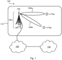
- Fig. 1 is a schematic diagram illustrating a communication network 100 where embodiments presented herein can be applied.
- the communication network 100 could be a third generation (3G) telecommunications network, a fourth generation (4G) telecommunications network, or a fifth (5G) telecommunications network and support any 3GPP telecommunications standard, where applicable.
- the communication network 100 comprises a radio network node 180 configured to provide network access to at least one terminal device 170a, 170b in a radio access network 110.
- the radio access network 110 is operatively connected to a core network 120.
- the core network 120 is in turn operatively connected to a service network 130, such as the Internet.
- the terminal devices 170a, 170b is thereby enabled to, via the radio access network node 180, access services of, and exchange data with, the service network 130.
- the radio access network node 180 comprises, is collocated with, is integrated with, or is in operational communications with, an antenna system 140.
- the antenna system 140 might be an active antenna system.
- the radio access network node 180 (via its antenna system 140) and the terminal devices 170a, 170b are configured to communicate with each other in beams 160a, 160b.
- the antenna system 140 is thus configured for beamformed transmission.
- the communication network 100 further comprises a controller 200. Further aspects of the controller 200 will be disclosed below.
- radio access network nodes 180 are radio base stations, base transceiver stations, Node Bs, evolved Node Bs, g Node Bs, access points, and access nodes, and backhaul nodes.
- terminal devices 170a, 170b are wireless devices, mobile stations, mobile phones, handsets, wireless local loop phones, user equipment (UE), smartphones, laptop computers, tablet computers, network equipped sensors, network equipped vehicles, and so-called Internet of Things devices.
- Fig. 2 schematically illustrates the antenna system 140 of Fig. 1 in more detail.
- the antenna system 140 comprises two transmission radio chains 141 and two receiver radio chains 142.
- the original signals x 0 and x 1 are first weighted by precoding coefficients w in an encoder part 143 to form signals u 0 and u 1 .
- the signals u 0 and u 1 can be used for PIM removal.
- the signals s 0 and s 1 at the receiver side are weighted by decoding coefficients h in a decoder part 152.
- the signals s 0 and s 1 (and also y 0 and/or y 1 ) can be used for PIM removal.
- the values of the precoding coefficients w and the decoding coefficients h are defined by which codeword is used for the beamformed transmission.
- the precoding coefficients are generated by the precoding matrix with the codebook information, i.e. the codebook index is pointed to certain precoding coefficients which have gain and phase information for beamforming in a specific direction.
- Each transmission radio chain 141 in turn comprises components, such as a digital-to-analogue (DAC) converter 144, a power amplifier (PA) 145, a bandpass filter (BPF) 146, and a single or double polarized antenna element 147.
- Each receiver radio chain 142 in turn comprises components, such as a single or double polarized antenna element 148, a BPF 149, a low noise amplifier (LNA) 150, and an analogue-to-digital (ADC) converter 151.
- the skilled person would understand how the antenna system 140 could be extended to comprise more than two transmission radio chains 141 and more than two receiver radio chains 142, such as in an AAS.
- Fig. 2 also schematically illustrates an external PIM source 190.
- Signals transmitted from one or more of the transmission radio chains 141 might thus be (distorted and) reflected by the external PIM source 190 and received by at least one of the receiver radio chains 142, thus causing PIM.
- PIM might be caused by any of the components 143-147 of the transmission radio chain 141. That is, in some embodiments, the PIM is caused by a PIM source 190 external to the antenna system 140 whereas in other embodiments, the PIM is caused by a passive electric component of at least one of the identified transmission radio chains 141.
- the embodiments disclosed herein therefore relate to mechanisms for PIM removal in an antenna system 140.
- a controller 200 of the antenna system 140 a method performed by the controller 200, a computer program product comprising code, for example in the form of a computer program, that when run on a controller 200, causes the controller 200 to perform the method.
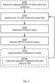
- Fig. 3 is a flowchart illustrating embodiments of methods for PIM removal in an antenna system 140. The methods are performed by the controller 200 of the antenna system 140. The methods are advantageously provided as computer programs 920.
- step S104 The controller 200 identifies, during transmission using codebook based beamforming, which transmission radio chains 141 of the antenna system 140 that cause a signal received by receiver radio chains 142 of the antenna system 140 to be impacted by PIM. These transmission radio chains 141 are identified based on which codeword in the codebook is used for the beamforming.
- the PIM is then mitigated based only on the signals transmitted by the identified transmission radio chains 141. That is, information of the signals as transmitted by any transmission radio chain 141 not having been identified is not utilized for the PIM mitigation.
- the controller 200 is configured to perform step S106: S106: The controller 200 determines a correction signal by subjecting the signals only as transmitted by the identified transmission radio chains 141 to a model of the PIM.
- step S108 The controller 200 removes PIM from the signal received by the receiver radio chains 142 by subtracting the correction signal from the signal received by the receiver radio chains 142.
- PIM is removed from all receiver radio chains 142 whereas in other aspects PIM is removed from only some of the receiver radio chains 142. Particularly, according to an embodiment, PIM is removed from the signal only from those of the receiver radio chains 142 having been identified as being impacted by the PIM. From which of the receiver radio chains 142 PIM needs to be removed can be determined in similar manner as which transmission radio chains 141 are identified as causing the receiver radio chains 142 to be impacted by PIM.
- This mapping can then be used to identify the transmission radio chains 141 that cause the PIM. That is, in some embodiments, this mapping is used to identify those of the transmission radio chains 141 that cause the aforementioned any signal received by the receiver radio chains 142 to be impacted by PIM during transmission using codebook based beamforming.
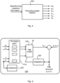
- Fig. 4 schematically illustrates a precoding weight selector 400 that selects precoding coefficients w and decoding coefficients h based on which codeword c is used for the beamforming.
- Each codebook entry, or codeword, used for the precoding provides a pointer to one or more specific PIM aggressors (i.e., to one or more of the transmission radio chains 141).
- PIM aggressors are thus the transmission radio chains 141 which will cause one or more of the receiver radio chains 142 to be impacted by PIM.
- the signals from other transmission radio chains 141 that will not cause PIM will not be used for PIM mitigation purposes. As such, the computation complexity of the PIM removal can be reduced.
- U [ u 0 , u 1 , ..., u K -1 ] denote the signals to the transmitter branches
- c is the codebook index
- M ( c ) is an index function that produces a list of transmitter signals to be used for PIM modelling for a codebook index c
- U ( M ( c )) defines the subset of the signals u 1 , u 1 , ..., u K -1 to be used for modelling, as selected by the index function M.
- the index function M selects k out of all K antenna branches (for example, 4 out of 64 antenna branches) as important for the PIM model, and the function f c is then adapted to match and remove (or even cancel) PIM of a receiver branch optimally using only these inputs.
- the function f c might be separately adapted for each receiver branch and each codebook index (but a similar process could be made to only cancel PIM for a selected few receiver branches if required).
- the index function M is different for each receiver branch.
- the modelled PIM signal x pim (i.e., the correction signal) will hence be subtracted from the received s o or s 1 in Fig. 2 depending on from which receiver radio chain 142 PIM is to be removed (i.e., from s 0 or s 1 ).
- the error from the subtraction can be minimized by adapting the model, resulting in a PIM-free received output signal.
- the processing involves filtering.
- subjecting the signal to the model involves filtering the signal with estimation coefficients of the model defining filter taps.
- filters used for this filtering.
- the signal is filtered using a non-linear filter.
- step S108 PIM is removed from the signal received by the receiver radio chains 142. Removing PIM from the signal received by the receiver radio chains 142 thus yields a PIM removed signal. In this respect, how much PIM that is removed depends on how well the correction signal captures the PIM. In turn, how well the correction signal captures the PIM depends on how well the model captures the PIM.
- a feedback mechanism is introduced by means of which the model is adapted.
- the controller 200 is configured to perform (optional) step S110: S110: The controller 200 adapts estimation coefficients of the model based on how much PIM is still present in the PIM removed signal.
- the estimation coefficients are selected according as the solution to an optimization problem where the object is to minimize the PIM. That is, in some embodiments, the controller 200 is configured to perform (optional) step S110a as part of step S110: S110a: The controller 200 determines which estimation coefficients that per each codeword in the codebook yield minimum PIM for those of the transmitter radio chains that per each codeword cause any signal received by the receiver radio chains 142 to be impacted by PIM.
- Fig. 5 schematically illustrates PIM removal in a controller 200 according to an embodiment.
- codeword c Based on which codeword c is used for the beamforming, those transmission radio chains of the antenna system that cause a signal received by receiver radio chains of the antenna system to be impacted by PIM are identified in TX chains identification block 510.
- the model coefficients are specific for each codeword. That is, in some embodiments, the model has one set of estimation coefficients per each codeword. If a new codeword c' is used for the beamforming, the new codeword c'is added to the codebook 520.
- a correction signal x pim is determined by subjecting the signals only as transmitted by the identified transmission radio chains to the model 530 of the PIM.
- the PIM is then removed from the signal s 0 or s 1 as received by the receiver radio chains by subtracting the correction signal x pim from the signal s 0 or s 1 as received by the receiver radio chains.
- the adaptation block 540 takes as input the PIM removed signal and determines which estimation coefficients that for the used codeword in the codebook yield minimum PIM. The estimation coefficients as adapted are then provided to the model 530.
- Fig. 6 is a flowchart of a method for adapting the model in accordance with embodiments disclosed herein.
- step S202 It is checked whether PIM removal has been performed for the codeword used for the beamforming or if the codeword indicates that the beamforming is in a new direction. If the beamforming is in a new direction step S203 is entered, and else step S204 is entered.
- a correction signal is determined by subjecting the signals only as transmitted by the identified transmission radio chains 141 to a model of the PIM.
- the PIM is modelled based on codebook information, such as which codeword was used for the beamforming. That is, the estimation coefficients of the model are selected dependent on which codeword was used for the beamforming. If the beamforming is in new direction (i.e., step S203 was entered) use default values of the estimation coefficients could be used.
- step S206 It is checked whether a minimum of the error energy has been reached, and hence if the power of the PIM removed signal has been minimized. If yes, step S207 is entered, and else step S208 is entered.
- S207 The estimation coefficients of the model are stored for later use when beamforming using the same codeword is performed.
- Step S208 The estimation coefficients of the model are adapted based on how much PIM is still present in the PIM removed signal. Step S204 is then entered again where the estimation coefficients as adapted in step S208 are used when determining the correction signal.
- how many transmission radio chains 141 that are to be considered by the model depends on how many transmission radio chains 141 there are in total in the antenna system 140. For example, if the total number of transmission radio chains 141 is comparatively high, only a small fraction of all the transmission radio chains 141 might be considered by the model whereas if the total number of transmission radio chains 141 is comparatively low, a large fraction of all the transmission radio chains 141 might be considered by the model in order to keep a reasonable level of complexity and computational cost at the controller 200. That is, in some embodiments, how many transmission radio chains 141 that are to be identified in step S104 is dependent on how many transmission radio chains 141 there are in total.
- how many transmission radio chains 141 that are to be considered by the model depends on the amount of PIM caused. In particular, in some embodiments, how many transmission radio chains 141 that are to be identified in step S104 is dependent on how much, or how many of, the receiver radio chains 142 are impacted by the PIM. In this respect, for a comparatively high level of PIM, more transmission radio chains 141 might be considered by the model than for only a comparatively low level of PIM. The design of the PIM model could thereby be adapted to handle different levels of PIM in an efficient manner.
- a fixed amount of transmission radio chains 141 are considered by the model. That is, in some embodiments, at most a predefined number of all transmission radio chains 141 are identified in in step S104. This might enable an efficient implementation of the PIM model since it could be designed for one particular number of transmission radio chains 141.
- Fig. 7 schematically illustrates, in terms of a number of functional units, the components of a controller 200 according to an embodiment.
- Processing circuitry 210 is provided using any combination of one or more of a suitable central processing unit (CPU), multiprocessor, microcontroller, digital signal processor (DSP), etc., capable of executing software instructions stored in a computer program product 910 (as in Fig. 9 ), e.g. in the form of a storage medium 230.
- the processing circuitry 210 may further be provided as at least one application specific integrated circuit (ASIC), or field programmable gate array (FPGA).
- ASIC application specific integrated circuit
- FPGA field programmable gate array
- the processing circuitry 210 is configured to cause the controller 200 to perform a set of operations, or steps, as disclosed above.
- the storage medium 230 may store the set of operations
- the processing circuitry 210 may be configured to retrieve the set of operations from the storage medium 230 to cause the controller 200 to perform the set of operations.
- the set of operations may be provided as a set of executable instructions.
- the processing circuitry 210 is thereby arranged to execute methods as herein disclosed.
- the storage medium 230 may also comprise persistent storage, which, for example, can be any single one or combination of magnetic memory, optical memory, solid state memory or even remotely mounted memory.
- the controller 200 may further comprise a communications interface 220 at least configured for communications with the antenna system 140. As such the communications interface 220 may comprise one or more transmitters and receivers, comprising analogue and digital components.
- the processing circuitry 210 controls the general operation of the controller 200 e.g. by sending data and control signals to the communications interface 220 and the storage medium 230, by receiving data and reports from the communications interface 220, and by retrieving data and instructions from the storage medium 230.
- Other components, as well as the related functionality, of the controller 200 are omitted in order not to obscure the concepts presented herein.
- Fig. 8 schematically illustrates, in terms of a number of functional modules, the components of a controller 200 according to an embodiment.
- the controller 200 of Fig. 8 comprises a number of functional modules; an identify module 210b configured to perform step S104, a determine module 210c configured to perform step S106, and a remove module 210d configured to perform step S108.
- the controller 200 of Fig. 8 may further comprise a number of optional functional modules, such as any of a determine module 210a configured to perform step S210a, an adapt module 210e configured to perform step S110, and a determine module 210f configured to perform step Sna.
- each functional module 210a-210f may in one embodiment be implemented only in hardware and in another embodiment with the help of software, i.e., the latter embodiment having computer program instructions stored on the storage medium 230 which when run on the processing circuitry makes the controller 200 perform the corresponding steps mentioned above in conjunction with Fig 8 .
- the modules correspond to parts of a computer program, they do not need to be separate modules therein, but the way in which they are implemented in software is dependent on the programming language used.
- one or more or all functional modules 210a-210f may be implemented by the processing circuitry 210, possibly in cooperation with the communications interface 220 and/or the storage medium 230.
- the processing circuitry 210 may thus be configured to from the storage medium 230 fetch instructions as provided by a functional module 210a-210f and to execute these instructions, thereby performing any steps as disclosed herein.
- the controller 200 may be provided as a standalone device or as a part of at least one further device.
- the controller 200 may be provided in a node of the radio access network and might be part of, integrated with, or collocated with, the antenna system 140.
- functionality of the controller 200 may be distributed between at least two devices, or nodes.
- a first portion of the instructions performed by the controller 200 may be executed in a first device
- a second portion of the of the instructions performed by the controller 200 may be executed in a second device; the herein disclosed embodiments are not limited to any particular number of devices on which the instructions performed by the controller 200 may be executed.
- the methods according to the herein disclosed embodiments are suitable to be performed by a controller 200 residing in a cloud computational environment.
- processing circuitry 210 may be distributed among a plurality of devices, or nodes. The same applies to the functional modules 210a-210f of Fig. 8 and the computer program 920 of Fig. 9 .
- Fig. 9 shows one example of a computer program product 910 comprising computer readable storage medium 930.
- a computer program 920 can be stored, which computer program 920 can cause the processing circuitry 210 and thereto operatively coupled entities and devices, such as the communications interface 220 and the storage medium 230, to execute methods according to embodiments described herein.
- the computer program 920 and/or computer program product 910 may thus provide means for performing any steps as herein disclosed.
- the computer program product 910 is illustrated as an optical disc, such as a CD (compact disc) or a DVD (digital versatile disc) or a Blu-Ray disc.
- the computer program product 910 could also be embodied as a memory, such as a random access memory (RAM), a read-only memory (ROM), an erasable programmable read-only memory (EPROM), or an electrically erasable programmable read-only memory (EEPROM) and more particularly as a non-volatile storage medium of a device in an external memory such as a USB (Universal Serial Bus) memory or a Flash memory, such as a compact Flash memory.
- the computer program 920 is here schematically shown as a track on the depicted optical disk, the computer program 920 can be stored in any way which is suitable for the computer program product 910.
Landscapes
- Engineering & Computer Science (AREA)
- Computer Networks & Wireless Communication (AREA)
- Signal Processing (AREA)
- Radio Transmission System (AREA)
Description
- Embodiments presented herein relate to a method, a controller, a computer program, and a computer program product for passive intermodulation removal in an antenna system.
- In general terms, passive intermodulation (PIM) is a type of distortion generated by nonlinearity of passive components, such as filters, duplexers, connectors, antennas and so forth at a cell site. Depending on the location of the component that generates the PIM, the PIM is categorized as either internal or external. For example, PIM generated by the filters of the transmission (TX) radio chains in the antenna system at the cell site is called internal PIM whereas PIM generated by a metal fence on the roof top of a building in vicinity of the cell site is called external PIM. PIM might cause the transmission power of the cell site to be backed off in order to avoid PIM to affect the receiver (RX) radio chains in the antenna system of the cell site, thus compromising the network performance.
- One way to mitigate PIM for active antenna systems (AASs) is to scale up existing solutions for classic antenna systems comprising from 2 to 8 TX radio chains (and equally may RX radio chains) to the AASs comprising from 16 to 64 or more TX radio chains or more (and equally may RX radio chains). One drawback of this approach is the computational cost that comes with it. Implementing a PIM cancellation function designed for traditional approaches in an AAS might be impractical.
- Another way to mitigate PIM is to use the PIM eigen components in the uplink to steer the nulls in the downlink. However, this principle only tries to avoid exciting the PIM source. Null steering in the downlink comes with a cost of reduced capacity in terms of total power and spatial steering.
- Further, in case of polynomial modeling of the PIM, the complexity of the third order non-linear modeling increases as O(N 3) with respect to the number of antennas N. For example, if six polynomial terms are needed to model the PIM for an antenna system with two TX antennas and two RX antennas, the number of terms will increase to 40. In an antenna system with four TX antennas and 4 RX antennas, 40.4 = 160 polynomial terms need to be computed and tracked for each time the beam direction of the transmitter is changed.
- Hence, there is still a need for an improved PIM mitigation, especially for AASs.
- Document
WO2019220179 relates to a method, a controller, a computer program, and a computer program product for passive intermodulation removal in an antenna system. - An object of embodiments herein is to provide efficient PIM mitigation, not suffering from the issues noted above, or at least where the above identified issues are reduced or mitigated.
- According to a first aspect there is presented a method for PIM removal in an antenna system. The method is performed by a controller of the antenna system. The method comprises identifying, during transmission using codebook based beamforming, which transmission radio chains of the antenna system that cause a signal received by receiver radio chains of the antenna system to be impacted by PIM. These transmission radio chains are identified based on which codeword in the codebook is used for the beamforming. The method comprises determining a correction signal by subjecting the signals only as transmitted by the identified transmission radio chains to a model of the PIM. The method comprises removing PIM from the signal received by the receiver radio chains by subtracting the correction signal from the signal received by the receiver radio chains.
- According to a second aspect there is presented a controller of an antenna system for PIM removal in the antenna system. The controller comprises processing circuitry. The processing circuitry is configured to cause the controller to identify, during transmission using codebook based beamforming, which transmission radio chains of the antenna system that cause a signal received by receiver radio chains of the antenna system to be impacted by PIM. These transmission radio chains are identified based on which codeword in the codebook is used for the beamforming. The processing circuitry is configured to cause the controller to determine a correction signal by subjecting the signals only as transmitted by the identified transmission radio chains to a model of the PIM. The processing circuitry is configured to cause the controller to remove PIM from the signal received by the receiver radio chains by subtracting the correction signal from the signal received by the receiver radio chains.
- According to a third aspect there is presented a controller of an antenna system for PIM removal in the antenna system. The controller comprises an identify module configured to identify, during transmission using codebook based beamforming, which transmission radio chains of the antenna system that cause a signal received by receiver radio chains of the antenna system to be impacted by PIM. These transmission radio chains are identified based on which codeword in the codebook is used for the beamforming. The controller comprises a determine module configured to determine a correction signal by subjecting the signals only as transmitted by the identified transmission radio chains to a model of the PIM. The controller comprises a remove module configured to remove PIM from the signal received by the receiver radio chains by subtracting the correction signal from the signal received by the receiver radio chains.
- According to a fourth aspect there is presented a computer program for PIM removal in an antenna system, the computer program comprising computer program code which, when run on a controller of the antenna system, causes the controller to perform a method according to the first aspect.
- According to a fifth aspect there is presented a computer program product comprising a computer program according to the fourth aspect and a computer readable storage medium on which the computer program is stored. The computer readable storage medium could be a non-transitory computer readable storage medium.
- Advantageously, these aspects provide efficient PIM mitigation.
- Advantageously, the proposed PIM removal does not suffer from the issues noted above.
- Advantageously, these aspects enable fast tracking and convergence of the PIM model
Advantageously, these aspects are based on the PIM model coefficients being computed in relation to the beamforming codebook information
Advantageously, these aspects result in a reduction in computational complexity compared to traditional mechanisms for PIM mitigation. - Other objectives, features and advantages of the enclosed embodiments will be apparent from the following detailed disclosure, from the attached dependent claims as well as from the drawings.
- Generally, all terms used in the claims are to be interpreted according to their ordinary meaning in the technical field, unless explicitly defined otherwise herein. All references to "a/an/the element, apparatus, component, means, module, step, etc." are to be interpreted openly as referring to at least one instance of the element, apparatus, component, means, module, step, etc., unless explicitly stated otherwise. The steps of any method disclosed herein do not have to be performed in the exact order disclosed, unless explicitly stated.
- The inventive concept is now described, by way of example, with reference to the accompanying drawings, in which:
-
Fig. 1 is a schematic diagram illustrating a communications network according to embodiments; -
Fig. 2 schematically illustrates an antenna system according to an embodiment; -
Figs. 3 and6 are flowcharts of methods according to embodiments; -
Fig. 4 schematically illustrates selection of precoding decoding weights according to an embodiment; -
Fig. 5 schematically illustrates PIM removal in a controller according to an embodiment; -
Fig. 7 is a schematic diagram showing functional units of a controller according to an embodiment; -
Fig. 8 is a schematic diagram showing functional modules of a controller according to an embodiment; and -
Fig. 9 shows one example of a computer program product comprising computer readable storage medium according to an embodiment. - The inventive concept will now be described more fully hereinafter with reference to the accompanying drawings, in which certain embodiments of the inventive concept are shown. This inventive concept may, however, be embodied in many different forms and should not be construed as limited to the embodiments set forth herein; rather, these embodiments are provided by way of example so that this disclosure will be thorough and complete, and will fully convey the scope of the inventive concept to those skilled in the art. Like numbers refer to like elements throughout the description. Any step or feature illustrated by dashed lines should be regarded as optional.
-
Fig. 1 is a schematic diagram illustrating acommunication network 100 where embodiments presented herein can be applied. Thecommunication network 100 could be a third generation (3G) telecommunications network, a fourth generation (4G) telecommunications network, or a fifth (5G) telecommunications network and support any 3GPP telecommunications standard, where applicable. - The
communication network 100 comprises aradio network node 180 configured to provide network access to at least oneterminal device radio access network 110. Theradio access network 110 is operatively connected to acore network 120. Thecore network 120 is in turn operatively connected to aservice network 130, such as the Internet. Theterminal devices access network node 180, access services of, and exchange data with, theservice network 130. - The radio
access network node 180 comprises, is collocated with, is integrated with, or is in operational communications with, anantenna system 140. Theantenna system 140 might be an active antenna system. The radio access network node 180 (via its antenna system 140) and theterminal devices beams antenna system 140 is thus configured for beamformed transmission. - The
communication network 100 further comprises acontroller 200. Further aspects of thecontroller 200 will be disclosed below. - Examples of radio
access network nodes 180 are radio base stations, base transceiver stations, Node Bs, evolved Node Bs, g Node Bs, access points, and access nodes, and backhaul nodes. Examples ofterminal devices -
Fig. 2 schematically illustrates theantenna system 140 ofFig. 1 in more detail. Theantenna system 140 comprises twotransmission radio chains 141 and tworeceiver radio chains 142. The original signals x 0 and x 1 are first weighted by precoding coefficients w in anencoder part 143 to form signals u 0 and u 1. The signals u 0 and u 1 can be used for PIM removal. The signals s 0 and s 1 at the receiver side are weighted by decoding coefficients h in adecoder part 152. The signals s 0 and s 1 (and also y 0 and/or y 1) can be used for PIM removal. The values of the precoding coefficients w and the decoding coefficients h are defined by which codeword is used for the beamformed transmission. The precoding coefficients are generated by the precoding matrix with the codebook information, i.e. the codebook index is pointed to certain precoding coefficients which have gain and phase information for beamforming in a specific direction. - Each
transmission radio chain 141 in turn comprises components, such as a digital-to-analogue (DAC)converter 144, a power amplifier (PA) 145, a bandpass filter (BPF) 146, and a single or doublepolarized antenna element 147. Eachreceiver radio chain 142 in turn comprises components, such as a single or doublepolarized antenna element 148, aBPF 149, a low noise amplifier (LNA) 150, and an analogue-to-digital (ADC)converter 151. The skilled person would understand how theantenna system 140 could be extended to comprise more than twotransmission radio chains 141 and more than tworeceiver radio chains 142, such as in an AAS. -
Fig. 2 also schematically illustrates anexternal PIM source 190. Signals transmitted from one or more of thetransmission radio chains 141 might thus be (distorted and) reflected by theexternal PIM source 190 and received by at least one of thereceiver radio chains 142, thus causing PIM. Additionally or alternatively, PIM might be caused by any of the components 143-147 of thetransmission radio chain 141. That is, in some embodiments, the PIM is caused by aPIM source 190 external to theantenna system 140 whereas in other embodiments, the PIM is caused by a passive electric component of at least one of the identifiedtransmission radio chains 141. - As disclosed above there is still a need for an improved PIM mitigation, especially for AASs.
- In further detail, existing mechanisms for PIM cancellation do not take advantage of the potential inherited system information that can be leveraged upon for an AAS system in order to reduce complexity and computational cost for removing PIM. As a consequence, PIM model tracking, as well as the PIM modeling itself, would be unnecessary complex and computationally costly.
- The embodiments disclosed herein therefore relate to mechanisms for PIM removal in an
antenna system 140. In order to obtain such mechanisms, there is provided acontroller 200 of theantenna system 140, a method performed by thecontroller 200, a computer program product comprising code, for example in the form of a computer program, that when run on acontroller 200, causes thecontroller 200 to perform the method. -
Fig. 3 is a flowchart illustrating embodiments of methods for PIM removal in anantenna system 140. The methods are performed by thecontroller 200 of theantenna system 140. The methods are advantageously provided ascomputer programs 920. - It is assumed that signal transmission is to be performed using codebook based beamforming. The beamforming is involves precoding the signal using coefficients in the codebook as specified by a codeword. The information of which codeword was used during the beamformed signal transmission is then utilized for PIM mitigation purposes. In particular, the
controller 200 is configured to perform step S104:
S104: Thecontroller 200 identifies, during transmission using codebook based beamforming, whichtransmission radio chains 141 of theantenna system 140 that cause a signal received byreceiver radio chains 142 of theantenna system 140 to be impacted by PIM. Thesetransmission radio chains 141 are identified based on which codeword in the codebook is used for the beamforming. - The PIM is then mitigated based only on the signals transmitted by the identified
transmission radio chains 141. That is, information of the signals as transmitted by anytransmission radio chain 141 not having been identified is not utilized for the PIM mitigation. In particular, thecontroller 200 is configured to perform step S106:
S106: Thecontroller 200 determines a correction signal by subjecting the signals only as transmitted by the identifiedtransmission radio chains 141 to a model of the PIM. - PIM is then removed from the signal by means of the determined correction signal. In particular, the
controller 200 is configured to perform step S108:
S108: Thecontroller 200 removes PIM from the signal received by thereceiver radio chains 142 by subtracting the correction signal from the signal received by thereceiver radio chains 142. - Embodiments relating to further details of PIM removal in an
antenna system 140 as performed by thecontroller 200 of theantenna system 140 will now be disclosed. - In some aspects, PIM is removed from all
receiver radio chains 142 whereas in other aspects PIM is removed from only some of thereceiver radio chains 142. Particularly, according to an embodiment, PIM is removed from the signal only from those of thereceiver radio chains 142 having been identified as being impacted by the PIM. From which of thereceiver radio chains 142 PIM needs to be removed can be determined in similar manner as whichtransmission radio chains 141 are identified as causing thereceiver radio chains 142 to be impacted by PIM. - There may be different ways to identify which
transmission radio chains 141 that cause the PIM. In some aspects, thetransmission radio chains 141 that cause the PIM are identified by means of a mapping betweentransmission radio chains 141 and codewords. Therefore, in some embodiments, thecontroller 200 is configured to perform (optional) step S102:
S102: Thecontroller 200 determines a mapping betweentransmission radio chains 141 and codewords by identifying which of thetransmission radio chains 141 that, for each codeword in the codebook, cause any signal as received by thereceiver radio chains 142 of theantenna system 140 to be impacted by PIM. - This mapping can then be used to identify the
transmission radio chains 141 that cause the PIM. That is, in some embodiments, this mapping is used to identify those of thetransmission radio chains 141 that cause the aforementioned any signal received by thereceiver radio chains 142 to be impacted by PIM during transmission using codebook based beamforming. -
Fig. 4 schematically illustrates aprecoding weight selector 400 that selects precoding coefficients w and decoding coefficients h based on which codeword c is used for the beamforming. Each codebook entry, or codeword, used for the precoding provides a pointer to one or more specific PIM aggressors (i.e., to one or more of the transmission radio chains 141). These PIM aggressors are thus thetransmission radio chains 141 which will cause one or more of thereceiver radio chains 142 to be impacted by PIM. The signals from othertransmission radio chains 141 that will not cause PIM (for example for which the beam is not reflected by the external PIM source 190) will not be used for PIM mitigation purposes. As such, the computation complexity of the PIM removal can be reduced. The correction signal,hereinafter denoted xpim , :
- The modelled PIM signal xpim (i.e., the correction signal) will hence be subtracted from the received s o or s 1 in
Fig. 2 depending on from whichreceiver radio chain 142 PIM is to be removed (i.e., from s 0 or s 1). As will be further disclosed below, the error from the subtraction can be minimized by adapting the model, resulting in a PIM-free received output signal. - There could be different ways to process the signal when the signal is subjected to the model of the PIM in step S106. In some aspects, the processing involves filtering. In particular, in some embodiments, subjecting the signal to the model involves filtering the signal with estimation coefficients of the model defining filter taps. There could be different examples of filters used for this filtering. In some embodiments, the signal is filtered using a non-linear filter.
- As disclosed above, in step S108, PIM is removed from the signal received by the
receiver radio chains 142. Removing PIM from the signal received by thereceiver radio chains 142 thus yields a PIM removed signal. In this respect, how much PIM that is removed depends on how well the correction signal captures the PIM. In turn, how well the correction signal captures the PIM depends on how well the model captures the PIM. - In some aspects, a feedback mechanism is introduced by means of which the model is adapted. In particular, in some embodiments, the
controller 200 is configured to perform (optional) step S110:
S110: Thecontroller 200 adapts estimation coefficients of the model based on how much PIM is still present in the PIM removed signal. - There could be different ways in which the estimation coefficients are adapted. In some aspects, the estimation coefficients are selected according as the solution to an optimization problem where the object is to minimize the PIM. That is, in some embodiments, the
controller 200 is configured to perform (optional) step S110a as part of step S110:
S110a: Thecontroller 200 determines which estimation coefficients that per each codeword in the codebook yield minimum PIM for those of the transmitter radio chains that per each codeword cause any signal received by thereceiver radio chains 142 to be impacted by PIM. - Reference is here made to
Fig. 5 which schematically illustrates PIM removal in acontroller 200 according to an embodiment. Based on which codeword c is used for the beamforming, those transmission radio chains of the antenna system that cause a signal received by receiver radio chains of the antenna system to be impacted by PIM are identified in TXchains identification block 510. In general terms, the model coefficients are specific for each codeword. That is, in some embodiments, the model has one set of estimation coefficients per each codeword. If a new codeword c' is used for the beamforming, the new codeword c'is added to thecodebook 520. A correction signal xpim is determined by subjecting the signals only as transmitted by the identified transmission radio chains to themodel 530 of the PIM. The PIM is then removed from the signal s 0 or s 1 as received by the receiver radio chains by subtracting the correction signal xpim from the signal s 0 or s 1 as received by the receiver radio chains. Theadaptation block 540 takes as input the PIM removed signal and determines which estimation coefficients that for the used codeword in the codebook yield minimum PIM. The estimation coefficients as adapted are then provided to themodel 530. -
Fig. 6 is a flowchart of a method for adapting the model in accordance with embodiments disclosed herein. - S201: Those
transmission radio chains 141 of theantenna system 140 that cause a signal received byreceiver radio chains 142 of theantenna system 140 to be impacted by PIM are identified based on codebook information. - S202: It is checked whether PIM removal has been performed for the codeword used for the beamforming or if the codeword indicates that the beamforming is in a new direction. If the beamforming is in a new direction step S203 is entered, and else step S204 is entered.
- S203: The new direction is added to the codebook.
- S204: A correction signal is determined by subjecting the signals only as transmitted by the identified
transmission radio chains 141 to a model of the PIM. The PIM is modelled based on codebook information, such as which codeword was used for the beamforming. That is, the estimation coefficients of the model are selected dependent on which codeword was used for the beamforming. If the beamforming is in new direction (i.e., step S203 was entered) use default values of the estimation coefficients could be used. - Which estimation coefficients that for the codeword yield minimum PIM are then estimated by steps S205, S206, and S208 being iteratively performed
S205: The error energy is measured as a difference between the received signal and the correction signal. This corresponds to the energy of the PIM removed signal. - S206: It is checked whether a minimum of the error energy has been reached, and hence if the power of the PIM removed signal has been minimized. If yes, step S207 is entered, and else step S208 is entered.
- S207: The estimation coefficients of the model are stored for later use when beamforming using the same codeword is performed.
- S208: The estimation coefficients of the model are adapted based on how much PIM is still present in the PIM removed signal. Step S204 is then entered again where the estimation coefficients as adapted in step S208 are used when determining the correction signal.
- Ways to identify which
transmission radio chains 141 that cause the PIM have been disclosed. Further in this respect, there could be different ways to determine how manytransmission radio chains 141 that are to be considered by the model and thus that are to be identified. Aspects relating thereto will now be disclosed. - In some aspects, how many
transmission radio chains 141 that are to be considered by the model depends on how manytransmission radio chains 141 there are in total in theantenna system 140. For example, if the total number oftransmission radio chains 141 is comparatively high, only a small fraction of all thetransmission radio chains 141 might be considered by the model whereas if the total number oftransmission radio chains 141 is comparatively low, a large fraction of all thetransmission radio chains 141 might be considered by the model in order to keep a reasonable level of complexity and computational cost at thecontroller 200. That is, in some embodiments, how manytransmission radio chains 141 that are to be identified in step S104 is dependent on how manytransmission radio chains 141 there are in total. - In some aspects, how many
transmission radio chains 141 that are to be considered by the model depends on the amount of PIM caused. In particular, in some embodiments, how manytransmission radio chains 141 that are to be identified in step S104 is dependent on how much, or how many of, thereceiver radio chains 142 are impacted by the PIM. In this respect, for a comparatively high level of PIM, moretransmission radio chains 141 might be considered by the model than for only a comparatively low level of PIM. The design of the PIM model could thereby be adapted to handle different levels of PIM in an efficient manner. - In some aspects, a fixed amount of
transmission radio chains 141 are considered by the model. That is, in some embodiments, at most a predefined number of alltransmission radio chains 141 are identified in in step S104. This might enable an efficient implementation of the PIM model since it could be designed for one particular number oftransmission radio chains 141. -
Fig. 7 schematically illustrates, in terms of a number of functional units, the components of acontroller 200 according to an embodiment.Processing circuitry 210 is provided using any combination of one or more of a suitable central processing unit (CPU), multiprocessor, microcontroller, digital signal processor (DSP), etc., capable of executing software instructions stored in a computer program product 910 (as inFig. 9 ), e.g. in the form of a storage medium 230. Theprocessing circuitry 210 may further be provided as at least one application specific integrated circuit (ASIC), or field programmable gate array (FPGA). - Particularly, the
processing circuitry 210 is configured to cause thecontroller 200 to perform a set of operations, or steps, as disclosed above. For example, the storage medium 230 may store the set of operations, and theprocessing circuitry 210 may be configured to retrieve the set of operations from the storage medium 230 to cause thecontroller 200 to perform the set of operations. The set of operations may be provided as a set of executable instructions. - Thus the
processing circuitry 210 is thereby arranged to execute methods as herein disclosed. The storage medium 230 may also comprise persistent storage, which, for example, can be any single one or combination of magnetic memory, optical memory, solid state memory or even remotely mounted memory. Thecontroller 200 may further comprise acommunications interface 220 at least configured for communications with theantenna system 140. As such thecommunications interface 220 may comprise one or more transmitters and receivers, comprising analogue and digital components. Theprocessing circuitry 210 controls the general operation of thecontroller 200 e.g. by sending data and control signals to thecommunications interface 220 and the storage medium 230, by receiving data and reports from thecommunications interface 220, and by retrieving data and instructions from the storage medium 230. Other components, as well as the related functionality, of thecontroller 200 are omitted in order not to obscure the concepts presented herein. -
Fig. 8 schematically illustrates, in terms of a number of functional modules, the components of acontroller 200 according to an embodiment. Thecontroller 200 ofFig. 8 comprises a number of functional modules; anidentify module 210b configured to perform step S104, a determinemodule 210c configured to perform step S106, and aremove module 210d configured to perform step S108. Thecontroller 200 ofFig. 8 may further comprise a number of optional functional modules, such as any of a determinemodule 210a configured to perform step S210a, an adaptmodule 210e configured to perform step S110, and a determinemodule 210f configured to perform step Sna. In general terms, eachfunctional module 210a-210f may in one embodiment be implemented only in hardware and in another embodiment with the help of software, i.e., the latter embodiment having computer program instructions stored on the storage medium 230 which when run on the processing circuitry makes thecontroller 200 perform the corresponding steps mentioned above in conjunction withFig 8 . It should also be mentioned that even though the modules correspond to parts of a computer program, they do not need to be separate modules therein, but the way in which they are implemented in software is dependent on the programming language used. Preferably, one or more or allfunctional modules 210a-210f may be implemented by theprocessing circuitry 210, possibly in cooperation with thecommunications interface 220 and/or the storage medium 230. Theprocessing circuitry 210 may thus be configured to from the storage medium 230 fetch instructions as provided by afunctional module 210a-210f and to execute these instructions, thereby performing any steps as disclosed herein. - The
controller 200 may be provided as a standalone device or as a part of at least one further device. For example, thecontroller 200 may be provided in a node of the radio access network and might be part of, integrated with, or collocated with, theantenna system 140. Alternatively, functionality of thecontroller 200 may be distributed between at least two devices, or nodes. Thus, a first portion of the instructions performed by thecontroller 200 may be executed in a first device, and a second portion of the of the instructions performed by thecontroller 200 may be executed in a second device; the herein disclosed embodiments are not limited to any particular number of devices on which the instructions performed by thecontroller 200 may be executed. Hence, the methods according to the herein disclosed embodiments are suitable to be performed by acontroller 200 residing in a cloud computational environment. Therefore, although asingle processing circuitry 210 is illustrated inFig. 7 theprocessing circuitry 210 may be distributed among a plurality of devices, or nodes. The same applies to thefunctional modules 210a-210f ofFig. 8 and thecomputer program 920 ofFig. 9 . -
Fig. 9 shows one example of acomputer program product 910 comprising computerreadable storage medium 930. On this computerreadable storage medium 930, acomputer program 920 can be stored, whichcomputer program 920 can cause theprocessing circuitry 210 and thereto operatively coupled entities and devices, such as thecommunications interface 220 and the storage medium 230, to execute methods according to embodiments described herein. Thecomputer program 920 and/orcomputer program product 910 may thus provide means for performing any steps as herein disclosed. - In the example of
Fig. 9 , thecomputer program product 910 is illustrated as an optical disc, such as a CD (compact disc) or a DVD (digital versatile disc) or a Blu-Ray disc. Thecomputer program product 910 could also be embodied as a memory, such as a random access memory (RAM), a read-only memory (ROM), an erasable programmable read-only memory (EPROM), or an electrically erasable programmable read-only memory (EEPROM) and more particularly as a non-volatile storage medium of a device in an external memory such as a USB (Universal Serial Bus) memory or a Flash memory, such as a compact Flash memory. Thus, while thecomputer program 920 is here schematically shown as a track on the depicted optical disk, thecomputer program 920 can be stored in any way which is suitable for thecomputer program product 910. - The inventive concept has mainly been described above with reference to a few embodiments. However, as is readily appreciated by a person skilled in the art, other embodiments than the ones disclosed above are equally possible within the scope of the inventive concept, as defined by the appended patent claims.
Claims (15)
- A method for passive intermodulation, PIM, removal in an antenna system (140), the method being performed by a controller (200) of the antenna system (140), the method comprising:identifying (S104), during transmission using codebook based beamforming, which transmission radio chains (141) of the antenna system (140) that cause a signal received by receiver radio chains (142) of the antenna system (140) to be impacted by PIM, wherein these transmission radio chains (141) are identified based on which codeword in the codebook is used for the beamforming;determining (S106) a correction signal by subjecting the signals only as transmitted by the identified transmission radio chains (141) to a model of the PIM; andremoving (S108) PIM from the signal received by the receiver radio chains (142) by subtracting the correction signal from the signal received by the receiver radio chains (142).
- The method according to claim 1, wherein subjecting the signal to the model involves filtering the signal with estimation coefficients of the model defining filter taps.
- The method according to claim 2, wherein the signal is filtered using a non-linear filter.
- The method according to any of the preceding claims, wherein removing PIM from the signal received by the receiver radio chains (142) yields a PIM removed signal, the method further comprising:
adapting (S110) estimation coefficients of the model based on how much PIM is still present in the PIM removed signal. - The method according to claim 4, the method further comprising:
determining (Snoa) which estimation coefficients that per each codeword in the codebook yield minimum PIM for those of the transmitter radio chains that per each codeword cause any signal received by the receiver radio chains (142) to be impacted by PIM. - The method according to any of the preceding claims, wherein the model has one set of estimation coefficients per each codeword.
- The method according to any of the preceding claims, the method further comprising:
determining (S102) a mapping between transmission radio chains (141) and codewords by identifying which of the transmission radio chains (141) that, for each codeword in the codebook, cause any signal as received by the receiver radio chains (142) of the antenna system (140) to be impacted by PIM. - The method according to claim 7, wherein said mapping is used to identify those of the transmission radio chains (141) that cause said any signal received by the receiver radio chains (142) to be impacted by PIM during transmission using codebook based beamforming.
- The method according to any of the preceding claims, wherein how many transmission radio chains (141) that are to be identified is dependent on how many transmission radio chains (141) there are in total.
- The method according to any of claims 1 to 8, wherein how many transmission radio chains (141) that are to be identified is dependent on how much, or how many of, the receiver radio chains (142) are impacted by the PIM.
- The method according to any of the preceding claims, wherein at most a predefined number of all transmission radio chains (141) are identified.
- The method according to any of the preceding claims, wherein PIM is removed from the signal only from those of the receiver radio chains (142) having been identified as being impacted by the PIM.
- A controller (200) of an antenna system (140) for passive intermodulation, PIM, removal in the antenna system (140), the controller (200) comprising processing circuitry (210), the processing circuitry being configured to cause the controller (200) to:identify, during transmission using codebook based beamforming, which transmission radio chains (141) of the antenna system (140) that cause a signal received by receiver radio chains (142) of the antenna system (140) to be impacted by PIM, wherein these transmission radio chains (141) are identified based on which codeword in the codebook is used for the beamforming;determine a correction signal by subjecting the signals only as transmitted by the identified transmission radio chains (141) to a model of the PIM; andremove PIM from the signal received by the receiver radio chains (142) by subtracting the correction signal from the signal received by the receiver radio chains (142).
- A computer program (920) for passive intermodulation, PIM, removal in an antenna system (140), the computer program comprising computer code which, when run on processing circuitry (210) of a controller (200) of the antenna system (140), causes the controller (200) to:identify (S104), during transmission using codebook based beamforming, which transmission radio chains (141) of the antenna system (140) that cause a signal received by receiver radio chains (142) of the antenna system (140) to be impacted by PIM, wherein these transmission radio chains (141) are identified based on which codeword in the codebook is used for the beamforming;determine (S106) a correction signal by subjecting the signals only as transmitted by the identified transmission radio chains (141) to a model of the PIM; andremove (S108) PIM from the signal received by the receiver radio chains (142) by subtracting the correction signal from the signal received by the receiver radio chains (142).
- A computer program product (910) comprising a computer program (920) according to claim 14, and a computer readable storage medium (930) on which the computer program is stored.
Applications Claiming Priority (1)
| Application Number | Priority Date | Filing Date | Title |
|---|---|---|---|
| PCT/CN2020/079862 WO2021184232A1 (en) | 2020-03-18 | 2020-03-18 | Removal of passive intermodulation in antenna systems |
Publications (3)
| Publication Number | Publication Date |
|---|---|
| EP4122106A1 EP4122106A1 (en) | 2023-01-25 |
| EP4122106A4 EP4122106A4 (en) | 2023-12-27 |
| EP4122106B1 true EP4122106B1 (en) | 2024-10-23 |
Family
ID=77768360
Family Applications (1)
| Application Number | Title | Priority Date | Filing Date |
|---|---|---|---|
| EP20925205.5A Active EP4122106B1 (en) | 2020-03-18 | 2020-03-18 | Removal of passive intermodulation in antenna systems |
Country Status (4)
| Country | Link |
|---|---|
| US (1) | US11996879B2 (en) |
| EP (1) | EP4122106B1 (en) |
| CN (1) | CN115244858B (en) |
| WO (1) | WO2021184232A1 (en) |
Families Citing this family (12)
| Publication number | Priority date | Publication date | Assignee | Title |
|---|---|---|---|---|
| EP4122106B1 (en) * | 2020-03-18 | 2024-10-23 | Telefonaktiebolaget LM Ericsson (publ.) | Removal of passive intermodulation in antenna systems |
| EP4205288A4 (en) | 2020-08-28 | 2024-10-30 | ISCO International, LLC | METHOD AND SYSTEM FOR MITIGATING NEAR-FIELD INTERFERENCE |
| US11476585B1 (en) | 2022-03-31 | 2022-10-18 | Isco International, Llc | Polarization shifting devices and systems for interference mitigation |
| US11502404B1 (en) | 2022-03-31 | 2022-11-15 | Isco International, Llc | Method and system for detecting interference and controlling polarization shifting to mitigate the interference |
| US11509071B1 (en) | 2022-05-26 | 2022-11-22 | Isco International, Llc | Multi-band polarization rotation for interference mitigation |
| US11515652B1 (en) | 2022-05-26 | 2022-11-29 | Isco International, Llc | Dual shifter devices and systems for polarization rotation to mitigate interference |
| US11984919B2 (en) * | 2022-10-03 | 2024-05-14 | Xilinx, Inc. | PIM cancellation architecture |
| US11949489B1 (en) | 2022-10-17 | 2024-04-02 | Isco International, Llc | Method and system for improving multiple-input-multiple-output (MIMO) beam isolation via alternating polarization |
| US11990976B2 (en) | 2022-10-17 | 2024-05-21 | Isco International, Llc | Method and system for polarization adaptation to reduce propagation loss for a multiple-input-multiple-output (MIMO) antenna |
| US12301315B1 (en) | 2023-12-29 | 2025-05-13 | Isco International, Llc | Methods and systems for detecting, measuring, and/or locating passive intermodulation sources via downlink (DL) signal injection |
| US12348285B1 (en) * | 2023-12-29 | 2025-07-01 | Isco International, Llc | Methods and systems for detecting, measuring, and/or locating passive intermodulation (PIM) sources via beamforming |
| US12301298B1 (en) | 2023-12-29 | 2025-05-13 | Isco International, Llc | Methods and systems for locating interference sources via angle of arrival (AoA) |
Family Cites Families (62)
| Publication number | Priority date | Publication date | Assignee | Title |
|---|---|---|---|---|
| US6081536A (en) * | 1997-06-20 | 2000-06-27 | Tantivy Communications, Inc. | Dynamic bandwidth allocation to transmit a wireless protocol across a code division multiple access (CDMA) radio link |
| CN102291222B (en) * | 2010-06-21 | 2014-07-09 | 电信科学技术研究院 | Method, device and system for feeding back precoding matrix indication |
| US9253786B2 (en) * | 2011-02-15 | 2016-02-02 | Telefonaktiebolaget L M Ericsson (Publ) | First network node and a second network node and methods therein |
| EP2710740A1 (en) * | 2011-05-20 | 2014-03-26 | Telefonaktiebolaget LM Ericsson (PUBL) | Dynamic cancellation of passive intermodulation interference |
| GB2510997B (en) * | 2012-05-21 | 2014-11-05 | Aceaxis Ltd | Detection of Intermodulation Products in a Wireless Network |
| US8890619B2 (en) * | 2012-08-02 | 2014-11-18 | Telefonaktiebolaget L M Ericsson (Publ) | PIM compensation in a receiver |
| US8855175B2 (en) * | 2012-08-02 | 2014-10-07 | Telefonaktiebolaget L M Ericsson (Publ) | Low complexity all-digital PIM compensator |
| CN103002493B (en) * | 2012-12-11 | 2015-05-27 | 华为技术有限公司 | Passive intermodulation detection method and device |
| CN103973351B (en) * | 2013-02-05 | 2017-12-22 | 华为技术有限公司 | A kind of method to be communicated in wireless communication system using code book and base station |
| US20140292609A1 (en) * | 2013-04-02 | 2014-10-02 | Dielectric, Llc | Device and Process for Reduction of Passive Intermodulation |
| US9660673B2 (en) * | 2013-06-26 | 2017-05-23 | Telefonaktiebolaget Lm Ericsson (Publ) | Apparatus and method for canceling inter-modulation products |
| JP5431609B1 (en) * | 2013-07-09 | 2014-03-05 | ソフトバンクモバイル株式会社 | Base station, interference suppression device, and interference suppression method |
| EP2884668B1 (en) * | 2013-12-12 | 2020-11-18 | Nokia Solutions and Networks Oy | Improvement of receiver sensitivity |
| US9461697B2 (en) * | 2014-02-27 | 2016-10-04 | Scintera Networks Llc | In-service monitoring and cancellation of passive intermodulation interferences |
| MX352915B (en) * | 2014-05-01 | 2017-12-14 | Ericsson Telefon Ab L M | Passive intermodulation detection. |
| CN103986482B (en) * | 2014-05-27 | 2016-02-03 | 北京理工大学 | A kind of passive intermodulation disturbance restraining method based on adaptive-filtering |
| MY182790A (en) * | 2014-07-14 | 2021-02-05 | Ericsson Telefon Ab L M | Cancelling crosstalk |
| CN104283580B (en) * | 2014-09-30 | 2016-09-28 | 上海华为技术有限公司 | The passive intermodulation PIM interference cancellation method of radio-frequency module and relevant apparatus |
| KR102365600B1 (en) * | 2015-06-09 | 2022-02-21 | 삼성전자주식회사 | Method for transmitting and receiving location information and apparatus therof |
| US10039022B2 (en) * | 2015-06-09 | 2018-07-31 | At&T Intellectual Property I, L.P. | Remote diagnosis and cancellation of passive intermodulation |
| WO2017006155A1 (en) * | 2015-07-08 | 2017-01-12 | Telefonaktiebolaget Lm Ericsson (Publ) | Uplink spectrum analysis technique for passive intermodulation (pim) detection |
| WO2017072552A1 (en) * | 2015-10-26 | 2017-05-04 | Telefonaktiebolaget Lm Ericsson (Publ) | Cell site passive intermodulation detection receiver |
| US20170141807A1 (en) * | 2015-11-12 | 2017-05-18 | Futurewei Technologies, Inc. | High Performance PIM Cancellation With Feedback |
| US20170141938A1 (en) * | 2015-11-12 | 2017-05-18 | Futurewei Technologies, Inc. | High Performance PIM Cancellation With Feed Forward Structure |
| WO2017081517A1 (en) * | 2015-11-12 | 2017-05-18 | Telefonaktiebolaget Lm Ericsson (Publ) | Duplexer |
| WO2017093784A1 (en) * | 2015-12-01 | 2017-06-08 | Telefonaktiebolaget Lm Ericsson (Publ) | Methods and devices for addressing passive intermodulation in wireless communication |
| WO2017157461A1 (en) * | 2016-03-18 | 2017-09-21 | Telefonaktiebolaget Lm Ericsson (Publ) | Method, controller, network node site and computer program |
| EP3430855B1 (en) * | 2016-03-18 | 2019-11-20 | Telefonaktiebolaget LM Ericsson (PUBL) | Methods of handling inter-modulation products interference at a network node |
| GB2551695B (en) * | 2016-06-07 | 2019-11-27 | Aceaxis Ltd | Mitigating Passive Intermodulation Interference in a MIMO Wireless Network |
| US9768812B1 (en) * | 2016-06-10 | 2017-09-19 | At&T Intellectual Property I, L.P. | Facilitation of passive intermodulation cancellation |
| EP3472939B1 (en) * | 2016-06-20 | 2020-04-29 | Telefonaktiebolaget LM Ericsson (PUBL) | A wireless communication network node arranged for reduction of passive intermodulation |
| WO2018026316A1 (en) * | 2016-08-01 | 2018-02-08 | Telefonaktiebolaget Lm Ericsson (Publ) | Pim suppression |
| EP3516777B1 (en) * | 2016-09-21 | 2020-07-01 | Telefonaktiebolaget LM Ericsson (publ) | Pim compensation at a transmitter's radio frequency port |
| EP3509223B1 (en) * | 2016-09-30 | 2023-02-22 | Huawei Technologies Co., Ltd. | Passive intermodulation (pim) cancellation method and device, and base station |
| CN109845118B (en) * | 2016-10-31 | 2020-12-15 | 华为技术有限公司 | A tower top device and passive intermodulation elimination method |
| DE112017006442T5 (en) * | 2016-12-21 | 2019-09-19 | Intel Corporation | WIRELESS COMMUNICATION TECHNOLOGY, DEVICES AND METHOD |
| US11056778B2 (en) * | 2017-04-26 | 2021-07-06 | Telefonaktiebolaget Lm Ericsson (Publ) | Radio assembly with modularized radios and interconnects |
| US10141961B1 (en) * | 2017-05-18 | 2018-11-27 | Nanosemi, Inc. | Passive intermodulation cancellation |
| JP2020520568A (en) * | 2017-05-30 | 2020-07-09 | テレフオンアクチーボラゲット エルエム エリクソン(パブル) | Beam selection for wireless transceivers |
| KR20200021947A (en) * | 2017-06-02 | 2020-03-02 | 인텔 아이피 코포레이션 | Beamformed Measurements for New Radios (NR) |
| JP2018207321A (en) * | 2017-06-06 | 2018-12-27 | 富士通株式会社 | Cancellation apparatus, cancellation method and radio communication apparatus |
| US10187098B1 (en) * | 2017-06-30 | 2019-01-22 | At&T Intellectual Property I, L.P. | Facilitation of passive intermodulation cancelation via machine learning |
| CN107453782A (en) * | 2017-08-23 | 2017-12-08 | 北京银河信通科技有限公司 | A kind of passive intermodulation interference cancellation system and method based on the estimation of double time delays |
| US10805130B2 (en) * | 2017-09-12 | 2020-10-13 | Intel IP Corporation | Signal cancellation system and method |
| KR102102059B1 (en) * | 2017-11-30 | 2020-04-17 | 연세대학교 산학협력단 | Full-duplex communication equipment for cancelling self-interference and method for cancelling self-interference |
| WO2019140669A1 (en) * | 2018-01-19 | 2019-07-25 | 华为技术有限公司 | Method for transmitting information, method for receiving information, transmitting apparatus and receiving apparatus |
| CN108777585B (en) * | 2018-02-09 | 2020-07-10 | 香港梵行科技有限公司 | A device and method for adaptively canceling passive intermodulation signals in a wireless transceiver system |
| CN111937318B (en) * | 2018-05-16 | 2022-07-08 | 瑞典爱立信有限公司 | Radiation pattern modification in the presence of interferers in a Frequency Division Duplex (FDD) system |
| CN112205056B (en) * | 2018-05-16 | 2024-10-01 | 瑞典爱立信有限公司 | Uplink-downlink coordinated scheduling with beam steering and passive intermodulation awareness |
| US11563512B2 (en) * | 2018-06-15 | 2023-01-24 | Telefonaktiebolaget Lm Ericsson (Publ) | Link-adaptation for passive intermodulation avoidance |
| WO2019245533A1 (en) * | 2018-06-19 | 2019-12-26 | Nokia Solutions And Networks Oy | Estmating a delay |
| US10924141B2 (en) * | 2018-07-15 | 2021-02-16 | Ubiqam Ltd. | Systems and methods for cancellation of passive intermodulation (PIM) for a wireless network receiver |
| CN209088944U (en) * | 2018-09-27 | 2019-07-09 | 香港梵行科技有限公司 | Device for adaptively canceling passive intermodulation signals |
| CN109495127B (en) * | 2018-09-27 | 2021-09-03 | 香港梵行科技有限公司 | Device and method for self-adaptively counteracting passive intermodulation signal and application equipment |
| CN209001952U (en) * | 2018-09-27 | 2019-06-18 | 香港梵行科技有限公司 | A device for adaptively canceling passive intermodulation signals |
| WO2020113928A1 (en) * | 2018-09-29 | 2020-06-11 | 香港梵行科技有限公司 | Apparatus and method for adaptively cancelling passive intermodulation signals |
| CN208955159U (en) * | 2018-11-21 | 2019-06-07 | 瑞典爱立信有限公司 | The adjustment structure and radio device of passive intermodulation characteristic |
| WO2020204772A1 (en) | 2019-04-01 | 2020-10-08 | Telefonaktiebolaget Lm Ericsson (Publ) | Network device and method therein for handling passive intermodulation signals in a wireless communications network |
| EP4104302A1 (en) * | 2020-02-10 | 2022-12-21 | Nokia Solutions and Networks Oy | Passive intermodulation aware beamforming |
| EP4122106B1 (en) * | 2020-03-18 | 2024-10-23 | Telefonaktiebolaget LM Ericsson (publ.) | Removal of passive intermodulation in antenna systems |
| EP4205288A4 (en) * | 2020-08-28 | 2024-10-30 | ISCO International, LLC | METHOD AND SYSTEM FOR MITIGATING NEAR-FIELD INTERFERENCE |
| WO2023037146A1 (en) * | 2021-09-10 | 2023-03-16 | Telefonaktiebolaget Lm Ericsson (Publ) | Method and system for iterative downlink passive intermodulation spatial avoidance |
-
2020
- 2020-03-18 EP EP20925205.5A patent/EP4122106B1/en active Active
- 2020-03-18 US US17/911,705 patent/US11996879B2/en active Active
- 2020-03-18 CN CN202080098638.7A patent/CN115244858B/en active Active
- 2020-03-18 WO PCT/CN2020/079862 patent/WO2021184232A1/en not_active Ceased
Also Published As
| Publication number | Publication date |
|---|---|
| EP4122106A1 (en) | 2023-01-25 |
| WO2021184232A1 (en) | 2021-09-23 |
| CN115244858A (en) | 2022-10-25 |
| US20230179252A1 (en) | 2023-06-08 |
| CN115244858B (en) | 2025-01-28 |
| EP4122106A4 (en) | 2023-12-27 |
| US11996879B2 (en) | 2024-05-28 |
| WO2021184232A9 (en) | 2021-11-11 |
Similar Documents
| Publication | Publication Date | Title |
|---|---|---|
| US11996879B2 (en) | Removal of passive intermodulation in antenna systems | |
| US11956001B2 (en) | Millimeter wave (mmWave) system and methods | |
| WO2017041858A1 (en) | Request of and feedback information for simultaneous wireless information and power transfer for multiple wireless devices | |
| US9794090B2 (en) | Transmitter and interference cancellation method | |
| EP2357768A1 (en) | Multiple-input multiple-output systems and methods for wireless communication thereof for reducing the quantization effect of precoding operations utilizing a finite codebook | |
| EP4302405B1 (en) | System and method for sampling signals | |
| WO2020239214A1 (en) | Controlling total average transmission power of a radio base station | |
| CN113169804B (en) | Disposal of damaged antenna branches | |
| EP3949145A1 (en) | Control of eirp of a radio base station | |
| CN114070355B (en) | Electronic device for eliminating self-interference signals and operation method thereof | |
| US20200059256A1 (en) | Low complexity mimo digital pre-distortion | |
| US20170208598A1 (en) | Distortion cancel device and distortion cancel method | |
| WO2020125526A1 (en) | Self-excitation offset method, apparatus and system | |
| US20150205758A1 (en) | Arithmetic device, arithmetic method, and wireless communication device | |
| EP3619817B1 (en) | Beamforming based on combined beams | |
| US20230216451A1 (en) | Linearization of a non-linear electronic device | |
| US10498386B2 (en) | Interference suppression in a radio transceiver device | |
| RU2632417C2 (en) | Method, system and device for precoding | |
| US20160380666A1 (en) | Transceiver device and method of processing signals | |
| CN119986730B (en) | Navigation signal correction method, device, equipment, medium, product and chip system | |
| WO2021155493A1 (en) | Method for mitigating passive intermodulation and an apparatus therefor | |
| US20230013213A1 (en) | Candidate beam selection for a terminal device | |
| CN112803976A (en) | Large-scale MIMO precoding method and system and electronic equipment | |
| US12633962B2 (en) | Full-duplex digital self-interference clear method and apparatus | |
| US20240405797A1 (en) | Full-duplex digital self-interference clear method and apparatus |
Legal Events
| Date | Code | Title | Description |
|---|---|---|---|
| STAA | Information on the status of an ep patent application or granted ep patent |
Free format text: STATUS: THE INTERNATIONAL PUBLICATION HAS BEEN MADE |
|
| PUAI | Public reference made under article 153(3) epc to a published international application that has entered the european phase |
Free format text: ORIGINAL CODE: 0009012 |
|
| STAA | Information on the status of an ep patent application or granted ep patent |
Free format text: STATUS: REQUEST FOR EXAMINATION WAS MADE |
|
| 17P | Request for examination filed |
Effective date: 20220628 |
|
| AK | Designated contracting states |
Kind code of ref document: A1 Designated state(s): AL AT BE BG CH CY CZ DE DK EE ES FI FR GB GR HR HU IE IS IT LI LT LU LV MC MK MT NL NO PL PT RO RS SE SI SK SM TR |
|
| DAV | Request for validation of the european patent (deleted) | ||
| DAX | Request for extension of the european patent (deleted) | ||
| REG | Reference to a national code |
Ref country code: DE Ref legal event code: R079 Free format text: PREVIOUS MAIN CLASS: H04B0001520000 Ipc: H04B0001525000 Ref document number: 602020040104 Country of ref document: DE |
|
| A4 | Supplementary search report drawn up and despatched |
Effective date: 20231123 |
|
| RIC1 | Information provided on ipc code assigned before grant |
Ipc: H04B 7/06 20060101ALI20231117BHEP Ipc: H04B 1/525 20150101AFI20231117BHEP |
|
| GRAP | Despatch of communication of intention to grant a patent |
Free format text: ORIGINAL CODE: EPIDOSNIGR1 |
|
| STAA | Information on the status of an ep patent application or granted ep patent |
Free format text: STATUS: GRANT OF PATENT IS INTENDED |
|
| INTG | Intention to grant announced |
Effective date: 20240715 |
|
| GRAS | Grant fee paid |
Free format text: ORIGINAL CODE: EPIDOSNIGR3 |
|
| GRAA | (expected) grant |
Free format text: ORIGINAL CODE: 0009210 |
|
| STAA | Information on the status of an ep patent application or granted ep patent |
Free format text: STATUS: THE PATENT HAS BEEN GRANTED |
|
| AK | Designated contracting states |
Kind code of ref document: B1 Designated state(s): AL AT BE BG CH CY CZ DE DK EE ES FI FR GB GR HR HU IE IS IT LI LT LU LV MC MK MT NL NO PL PT RO RS SE SI SK SM TR |
|
| REG | Reference to a national code |
Ref country code: GB Ref legal event code: FG4D |
|
| REG | Reference to a national code |
Ref country code: CH Ref legal event code: EP |
|
| REG | Reference to a national code |
Ref country code: DE Ref legal event code: R096 Ref document number: 602020040104 Country of ref document: DE |
|
| REG | Reference to a national code |
Ref country code: IE Ref legal event code: FG4D |
|
| REG | Reference to a national code |
Ref country code: LT Ref legal event code: MG9D |
|
| REG | Reference to a national code |
Ref country code: NL Ref legal event code: MP Effective date: 20241023 |
|
| REG | Reference to a national code |
Ref country code: AT Ref legal event code: MK05 Ref document number: 1735688 Country of ref document: AT Kind code of ref document: T Effective date: 20241023 |
|
| PG25 | Lapsed in a contracting state [announced via postgrant information from national office to epo] |
Ref country code: NL Free format text: LAPSE BECAUSE OF FAILURE TO SUBMIT A TRANSLATION OF THE DESCRIPTION OR TO PAY THE FEE WITHIN THE PRESCRIBED TIME-LIMIT Effective date: 20241023 |
|
| PG25 | Lapsed in a contracting state [announced via postgrant information from national office to epo] |
Ref country code: NL Free format text: LAPSE BECAUSE OF FAILURE TO SUBMIT A TRANSLATION OF THE DESCRIPTION OR TO PAY THE FEE WITHIN THE PRESCRIBED TIME-LIMIT Effective date: 20241023 |
|
| PG25 | Lapsed in a contracting state [announced via postgrant information from national office to epo] |
Ref country code: IS Free format text: LAPSE BECAUSE OF FAILURE TO SUBMIT A TRANSLATION OF THE DESCRIPTION OR TO PAY THE FEE WITHIN THE PRESCRIBED TIME-LIMIT Effective date: 20250223 Ref country code: PT Free format text: LAPSE BECAUSE OF FAILURE TO SUBMIT A TRANSLATION OF THE DESCRIPTION OR TO PAY THE FEE WITHIN THE PRESCRIBED TIME-LIMIT Effective date: 20250224 Ref country code: HR Free format text: LAPSE BECAUSE OF FAILURE TO SUBMIT A TRANSLATION OF THE DESCRIPTION OR TO PAY THE FEE WITHIN THE PRESCRIBED TIME-LIMIT Effective date: 20241023 |
|
| PG25 | Lapsed in a contracting state [announced via postgrant information from national office to epo] |
Ref country code: FI Free format text: LAPSE BECAUSE OF FAILURE TO SUBMIT A TRANSLATION OF THE DESCRIPTION OR TO PAY THE FEE WITHIN THE PRESCRIBED TIME-LIMIT Effective date: 20241023 |
|
| PG25 | Lapsed in a contracting state [announced via postgrant information from national office to epo] |
Ref country code: BG Free format text: LAPSE BECAUSE OF FAILURE TO SUBMIT A TRANSLATION OF THE DESCRIPTION OR TO PAY THE FEE WITHIN THE PRESCRIBED TIME-LIMIT Effective date: 20241023 |
|
| PG25 | Lapsed in a contracting state [announced via postgrant information from national office to epo] |
Ref country code: ES Free format text: LAPSE BECAUSE OF FAILURE TO SUBMIT A TRANSLATION OF THE DESCRIPTION OR TO PAY THE FEE WITHIN THE PRESCRIBED TIME-LIMIT Effective date: 20241023 |
|
| PG25 | Lapsed in a contracting state [announced via postgrant information from national office to epo] |
Ref country code: NO Free format text: LAPSE BECAUSE OF FAILURE TO SUBMIT A TRANSLATION OF THE DESCRIPTION OR TO PAY THE FEE WITHIN THE PRESCRIBED TIME-LIMIT Effective date: 20250123 |
|
| PG25 | Lapsed in a contracting state [announced via postgrant information from national office to epo] |
Ref country code: AT Free format text: LAPSE BECAUSE OF FAILURE TO SUBMIT A TRANSLATION OF THE DESCRIPTION OR TO PAY THE FEE WITHIN THE PRESCRIBED TIME-LIMIT Effective date: 20241023 Ref country code: GR Free format text: LAPSE BECAUSE OF FAILURE TO SUBMIT A TRANSLATION OF THE DESCRIPTION OR TO PAY THE FEE WITHIN THE PRESCRIBED TIME-LIMIT Effective date: 20250124 Ref country code: LV Free format text: LAPSE BECAUSE OF FAILURE TO SUBMIT A TRANSLATION OF THE DESCRIPTION OR TO PAY THE FEE WITHIN THE PRESCRIBED TIME-LIMIT Effective date: 20241023 |
|
| PG25 | Lapsed in a contracting state [announced via postgrant information from national office to epo] |
Ref country code: PL Free format text: LAPSE BECAUSE OF FAILURE TO SUBMIT A TRANSLATION OF THE DESCRIPTION OR TO PAY THE FEE WITHIN THE PRESCRIBED TIME-LIMIT Effective date: 20241023 |
|
| PG25 | Lapsed in a contracting state [announced via postgrant information from national office to epo] |
Ref country code: RS Free format text: LAPSE BECAUSE OF FAILURE TO SUBMIT A TRANSLATION OF THE DESCRIPTION OR TO PAY THE FEE WITHIN THE PRESCRIBED TIME-LIMIT Effective date: 20250123 |
|
| PG25 | Lapsed in a contracting state [announced via postgrant information from national office to epo] |
Ref country code: SM Free format text: LAPSE BECAUSE OF FAILURE TO SUBMIT A TRANSLATION OF THE DESCRIPTION OR TO PAY THE FEE WITHIN THE PRESCRIBED TIME-LIMIT Effective date: 20241023 |
|
| PG25 | Lapsed in a contracting state [announced via postgrant information from national office to epo] |
Ref country code: DK Free format text: LAPSE BECAUSE OF FAILURE TO SUBMIT A TRANSLATION OF THE DESCRIPTION OR TO PAY THE FEE WITHIN THE PRESCRIBED TIME-LIMIT Effective date: 20241023 |
|
| PG25 | Lapsed in a contracting state [announced via postgrant information from national office to epo] |
Ref country code: EE Free format text: LAPSE BECAUSE OF FAILURE TO SUBMIT A TRANSLATION OF THE DESCRIPTION OR TO PAY THE FEE WITHIN THE PRESCRIBED TIME-LIMIT Effective date: 20241023 |
|
| PG25 | Lapsed in a contracting state [announced via postgrant information from national office to epo] |
Ref country code: RO Free format text: LAPSE BECAUSE OF FAILURE TO SUBMIT A TRANSLATION OF THE DESCRIPTION OR TO PAY THE FEE WITHIN THE PRESCRIBED TIME-LIMIT Effective date: 20241023 |
|
| REG | Reference to a national code |
Ref country code: DE Ref legal event code: R097 Ref document number: 602020040104 Country of ref document: DE |
|
| PG25 | Lapsed in a contracting state [announced via postgrant information from national office to epo] |
Ref country code: SK Free format text: LAPSE BECAUSE OF FAILURE TO SUBMIT A TRANSLATION OF THE DESCRIPTION OR TO PAY THE FEE WITHIN THE PRESCRIBED TIME-LIMIT Effective date: 20241023 |
|
| PG25 | Lapsed in a contracting state [announced via postgrant information from national office to epo] |
Ref country code: CZ Free format text: LAPSE BECAUSE OF FAILURE TO SUBMIT A TRANSLATION OF THE DESCRIPTION OR TO PAY THE FEE WITHIN THE PRESCRIBED TIME-LIMIT Effective date: 20241023 |
|
| PG25 | Lapsed in a contracting state [announced via postgrant information from national office to epo] |
Ref country code: IT Free format text: LAPSE BECAUSE OF FAILURE TO SUBMIT A TRANSLATION OF THE DESCRIPTION OR TO PAY THE FEE WITHIN THE PRESCRIBED TIME-LIMIT Effective date: 20241023 |
|
| PLBE | No opposition filed within time limit |
Free format text: ORIGINAL CODE: 0009261 |
|
| STAA | Information on the status of an ep patent application or granted ep patent |
Free format text: STATUS: NO OPPOSITION FILED WITHIN TIME LIMIT |
|
| PG25 | Lapsed in a contracting state [announced via postgrant information from national office to epo] |
Ref country code: SE Free format text: LAPSE BECAUSE OF FAILURE TO SUBMIT A TRANSLATION OF THE DESCRIPTION OR TO PAY THE FEE WITHIN THE PRESCRIBED TIME-LIMIT Effective date: 20241023 |
|
| 26N | No opposition filed |
Effective date: 20250724 |
|
| PG25 | Lapsed in a contracting state [announced via postgrant information from national office to epo] |
Ref country code: MC Free format text: LAPSE BECAUSE OF FAILURE TO SUBMIT A TRANSLATION OF THE DESCRIPTION OR TO PAY THE FEE WITHIN THE PRESCRIBED TIME-LIMIT Effective date: 20241023 |
|
| REG | Reference to a national code |
Ref country code: CH Ref legal event code: H13 Free format text: ST27 STATUS EVENT CODE: U-0-0-H10-H13 (AS PROVIDED BY THE NATIONAL OFFICE) Effective date: 20251023 |
|
| PG25 | Lapsed in a contracting state [announced via postgrant information from national office to epo] |
Ref country code: LU Free format text: LAPSE BECAUSE OF NON-PAYMENT OF DUE FEES Effective date: 20250318 |
|
| REG | Reference to a national code |
Ref country code: BE Ref legal event code: MM Effective date: 20250331 |
|
| PG25 | Lapsed in a contracting state [announced via postgrant information from national office to epo] |
Ref country code: FR Free format text: LAPSE BECAUSE OF NON-PAYMENT OF DUE FEES Effective date: 20250331 |
|
| PG25 | Lapsed in a contracting state [announced via postgrant information from national office to epo] |
Ref country code: BE Free format text: LAPSE BECAUSE OF NON-PAYMENT OF DUE FEES Effective date: 20250331 |
|
| PG25 | Lapsed in a contracting state [announced via postgrant information from national office to epo] |
Ref country code: CH Free format text: LAPSE BECAUSE OF NON-PAYMENT OF DUE FEES Effective date: 20250331 |
|
| PG25 | Lapsed in a contracting state [announced via postgrant information from national office to epo] |
Ref country code: IE Free format text: LAPSE BECAUSE OF NON-PAYMENT OF DUE FEES Effective date: 20250318 |
|
| PGFP | Annual fee paid to national office [announced via postgrant information from national office to epo] |
Ref country code: GB Payment date: 20260327 Year of fee payment: 7 |
|
| PGFP | Annual fee paid to national office [announced via postgrant information from national office to epo] |
Ref country code: DE Payment date: 20260327 Year of fee payment: 7 |