EP4120924B1 - Depth penetration limiter for a tissue repair device - Google Patents
Depth penetration limiter for a tissue repair device Download PDFInfo
- Publication number
- EP4120924B1 EP4120924B1 EP21710758.0A EP21710758A EP4120924B1 EP 4120924 B1 EP4120924 B1 EP 4120924B1 EP 21710758 A EP21710758 A EP 21710758A EP 4120924 B1 EP4120924 B1 EP 4120924B1
- Authority
- EP
- European Patent Office
- Prior art keywords
- limiter member
- shaft
- depth
- repair device
- tissue repair
- Prior art date
- Legal status (The legal status is an assumption and is not a legal conclusion. Google has not performed a legal analysis and makes no representation as to the accuracy of the status listed.)
- Active
Links
Images



Classifications
-
- A—HUMAN NECESSITIES
- A61—MEDICAL OR VETERINARY SCIENCE; HYGIENE
- A61B—DIAGNOSIS; SURGERY; IDENTIFICATION
- A61B17/00—Surgical instruments, devices or methods
- A61B17/04—Surgical instruments, devices or methods for suturing wounds; Holders or packages for needles or suture materials
- A61B17/0401—Suture anchors, buttons or pledgets, i.e. means for attaching sutures to bone, cartilage or soft tissue; Instruments for applying or removing suture anchors
-
- A—HUMAN NECESSITIES
- A61—MEDICAL OR VETERINARY SCIENCE; HYGIENE
- A61B—DIAGNOSIS; SURGERY; IDENTIFICATION
- A61B17/00—Surgical instruments, devices or methods
- A61B17/04—Surgical instruments, devices or methods for suturing wounds; Holders or packages for needles or suture materials
- A61B17/0469—Suturing instruments for use in minimally invasive surgery, e.g. endoscopic surgery
-
- A—HUMAN NECESSITIES
- A61—MEDICAL OR VETERINARY SCIENCE; HYGIENE
- A61B—DIAGNOSIS; SURGERY; IDENTIFICATION
- A61B17/00—Surgical instruments, devices or methods
- A61B17/04—Surgical instruments, devices or methods for suturing wounds; Holders or packages for needles or suture materials
- A61B17/06—Needles ; Sutures; Needle-suture combinations; Holders or packages for needles or suture materials
-
- A—HUMAN NECESSITIES
- A61—MEDICAL OR VETERINARY SCIENCE; HYGIENE
- A61B—DIAGNOSIS; SURGERY; IDENTIFICATION
- A61B17/00—Surgical instruments, devices or methods
- A61B17/04—Surgical instruments, devices or methods for suturing wounds; Holders or packages for needles or suture materials
- A61B17/0401—Suture anchors, buttons or pledgets, i.e. means for attaching sutures to bone, cartilage or soft tissue; Instruments for applying or removing suture anchors
- A61B2017/0409—Instruments for applying suture anchors
-
- A—HUMAN NECESSITIES
- A61—MEDICAL OR VETERINARY SCIENCE; HYGIENE
- A61B—DIAGNOSIS; SURGERY; IDENTIFICATION
- A61B17/00—Surgical instruments, devices or methods
- A61B17/04—Surgical instruments, devices or methods for suturing wounds; Holders or packages for needles or suture materials
- A61B17/06—Needles ; Sutures; Needle-suture combinations; Holders or packages for needles or suture materials
- A61B2017/06052—Needle-suture combinations in which a suture is extending inside a hollow tubular needle, e.g. over the entire length of the needle
Definitions
- Fibrous tissue wounds such as muscle, ligament, and meniscal tears
- a surgeon To close a fibrous tissue wound, a surgeon often inserts a needle of a tissue repair device into the tissue to successively deploy two anchors attached to the same suture on opposite sides of the wound, and reduces the length of the suture between the two anchors to close the sides of the wound.
- a number of such tissue repair devices use a finger-engageable, sliding limiter that moves a depth tube to control the penetration depth of the delivery needle.
- US 2010/0130989 A1 relates to a tissue repair device.
- the invention is defined by claim 1. Described herein is a depth penetration limiter for use with a meniscal repair device which has a built-in, self-stopper feature to prevent the limiter from disengaging from the device housing.
- the self-stopper feature is a cantilevered flexure on a bottom surface of the limiter that deflects as it is moved through the housing. As the flexure passes the edge of a recess in the housing, the flexure returns to its original shape, trapping the flexure within the recess and preventing further distal movement of the limiter/depth tube.
- a connection feature on the limiter advantageously provides increased pull-off resistance of the depth tube from the limiter.
- a tissue repair device of this disclosure includes a handle having a proximal end and a distal end, and a needle assembly disposed at least partially within a channel extending through the handle.
- a depth tube including a cannulation is configured to receive at least a portion of the needle assembly therein.
- a limiter member includes a housing disposed within the handle and a shaft extending from the distal end of the handle. The shaft is configured to engage the cannulation of the depth tube.
- the limiter member has a finger-engageable actuator for allowing axial movement of the depth tube relative to the needle assembly.
- the housing of the limiter member includes a flexure configured to engage a recess in the housing to limit distal movement of the limiter member relative to the housing.
- a proximal side of the flexure includes a cantilevered surface configured to allow for proximal movement of the limiter member relative to the housing.
- an outer surface of the shaft of the limiter member has at least one connection feature for increasing pull-out resistance between the shaft of the limiter member and the cannulation of the depth tube.
- the at least one connection feature is at least one circumferential rib formed by a conical section of the shaft of the limiter member.
- the at least one connection feature is a plurality of barbs on an outer surface of the shaft of the limiter member.
- the handle has a hub coupled to a distal end of a tube extending through the handle, and the housing of the limiter member is disposed within the hub.
- a top portion of the housing extends through an open slot in the hub.
- a proximal portion of the depth tube and a distal end of the needle assembly include coordinated markings for indicating a tissue penetration depth of the needle assembly.
- the depth tube is comprised of a flexible material such that a proximal end of the depth tube configured to stretch about an outer surface of the shaft of the limiter member.
- the limiter member includes tabs for successively engaging grooves of the handle upon longitudinal movement of the limiter member within the handle.
- tissue repair device of this device include a handle having a proximal end and a distal end, and a needle assembly disposed at least partially within a channel extending through the handle.
- a depth tube including a cannulation is configured to receive at least a portion of the needle assembly therein.
- a limiter member includes a housing disposed within the handle and a shaft extending from the distal end of the handle. The shaft is configured to engage the cannulation of the depth tube.
- the limiter member has a finger-engageable actuator for allowing axial movement of the depth tube relative to the needle assembly.
- An outer surface of the shaft of the limiter member includes at least one connection feature for increasing pull-out resistance between the shaft of the limiter member and the cannulation of the depth tube.
- the housing of the limiter member includes a flexure configured to engage a recess in the housing to limit distal movement of the limiter member relative to the housing.
- a proximal side of the flexure includes a cantilevered surface configured to allow for proximal movement of the limiter member relative to the housing.
- the at least one connection feature is at least one circumferential rib formed by a conical section of the shaft of the limiter member. In other examples, the at least one connection feature is a plurality of barbs on an outer surface of the shaft of the limiter member.
- the handle includes a hub coupled to a distal end of a tube extending through the handle, and the housing of the limiter member is disposed within the hub.
- a top portion of the housing extends through an open slot in the hub.
- a proximal portion of the depth tube and a distal end of the needle assembly include coordinated markings for indicating a tissue penetration depth of the needle assembly.
- the depth tube is comprised of a flexible material such that a proximal end of the depth tube is configured to stretch about an outer surface of the shaft of the limiter member.
- the limiter member includes tabs for successively engaging grooves of the handle upon longitudinal movement of the limiter member within the handle.
- the terms “about” and “substantially” are used to represent the inherent degree of uncertainty that may be attributed to any quantitative comparison, value, measurement, or other representation.
- the terms “about” and “substantially” are also used herein to represent the degree by which a quantitative representation may vary from a stated reference without resulting in a change in the basic function of the subject matter at issue.
- “Comprise,” “include,” and/or plural forms of each are open ended and include the listed parts and can include additional parts that are not listed.
- “And/or” is open-ended and includes one or more of the listed parts and combinations of the listed parts. Use of the terms “above,” “below” and the like is intended only to help in the clear description of the present disclosure and are not intended to limit the structure, positioning and/or operation of the tissue repair device in any manner.
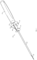
- the device 100 generally includes a handle 110, a knob 120 coupled to the handle 110, a tube 130 disposed within the knob 120 and the handle 110, and a hub 170 coupled to the tube 130.
- the depth penetration limiter 400 of this disclosure is disposed within the hub 170 and coupled to a depth tube 300, as further described below.
- a needle assembly 180 extends through the depth tube 300 and houses at least one suture anchor (not shown) for deployment from the needle assembly 180 into tissue.
- Other non-limiting examples of the handle 110, the knob 120, the tube 130, the hub 170 and the needle assembly 180 are disclosed in U.S. Patent No. 8,888,798 to Bourque et al.
- FIG. 2A shows the assembled hub 170 having a first part 171 ( FIG. 2B ) and a second part 172 ( FIG. 2C ).
- the first part 171 and the second part 172 define a cannulation 176 extending through the hub 170.
- Both the first part 171 and the second part 172 include a first section 171a, 172a and a second section 171b, 172b.
- An open slot 173 extends between the first sections 171a, 172a in communication with the cannulation 176.
- the first sections 171a, 172a also include a front portion 171a', 172a' and grooves 171a",172a", the purpose of which will be described in more detail below.
- Each part 171, 172 also includes tabs 171d, 172d located on an outer surface of the second sections 171b, 172b.
- the second sections 171b, 172b are housed within the tube 130 ( FIG. 1 ) such that the tabs 171d, 172d are disposed within holes 132 of the tube 130, thereby coupling the hub 170 to the tube 130.
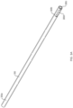
- the depth tube 300 includes a distal portion 300a, a proximal portion 300b, and a cannulation 300c for passage of the needle assembly 180.
- the proximal portion 300b of the depth tube 300 includes markings 300d.
- the depth tube 300 can be made of a flexible material such that the proximal portion 300b of the depth tube 300 can be stretched about an outer surface of the depth penetration limiter 400, as further described below.
- the depth penetration limiter 400 of this disclosure is coupled to the proximal portion 300b of the depth tube 300 while the needle assembly 180 extends from the distal portion 300a of the depth tube 300.
- a distal end of the needle assembly 180 also includes markings 182 for indicating a penetration depth of the needle assembly 180 during repair.
- the front portions 171a', 172a' of the hub 170 and a front portion 300a' of the depth tube 300 will continue to align with the respective markings 300d, 182 such that the markings 300d, 182 with which the fronts portions 171a', 172a', 300a' are respectively aligned will be equivalent to each other.
- the front portion 300a' is also aligned with a marking 182 that corresponds to 1 mm.
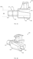
- the depth penetration limiter 400 includes a shaft 401, a housing 402 coupled to the shaft 401, and a cannulation 403 for passage of the needle assembly 180 and/or an actuator 184 ( FIG. 4D ).
- a flexure 409 is coupled to an inner surface of the cannulation 403 such that the flexure extends below the housing 402, the purpose of which will be described in more detail below.
- the shaft 401 includes a connection feature 407 which is configured to couple the shaft 401 to the proximal portion 300b of the depth tube 300.
- connection feature 407 is one or more circumferential ribs 404 defined by a cone-shaped section 405 of the shaft 401.
- the connection feature 407 is a plurality of barbs 406 disposed about a circumference of the shaft 401.
- a cross-section of the barbs 406 could be cylindrical, mirror-symmetric, rectangular, triangular, pentangular, star-shaped etc.
- the connection feature 407 is configured to provide sufficient assembly force as well as to increase pull-off resistance of the depth tube 300 from the shaft 401.
- the depth tube 300 can be assembled to the shaft 401 by stretching the proximal portion 300b of the depth tube 300 around the connection feature 407 and allowing the depth tube 300 to relax back around the surface of the shaft 401.
Landscapes
- Health & Medical Sciences (AREA)
- Surgery (AREA)
- Life Sciences & Earth Sciences (AREA)
- Medical Informatics (AREA)
- Animal Behavior & Ethology (AREA)
- Engineering & Computer Science (AREA)
- Biomedical Technology (AREA)
- Heart & Thoracic Surgery (AREA)
- Veterinary Medicine (AREA)
- Molecular Biology (AREA)
- Nuclear Medicine, Radiotherapy & Molecular Imaging (AREA)
- General Health & Medical Sciences (AREA)
- Public Health (AREA)
- Rheumatology (AREA)
- Surgical Instruments (AREA)
- Prostheses (AREA)
- Sampling And Sample Adjustment (AREA)
Description
- Fibrous tissue wounds, such as muscle, ligament, and meniscal tears, can be repaired arthroscopically using sutures. To close a fibrous tissue wound, a surgeon often inserts a needle of a tissue repair device into the tissue to successively deploy two anchors attached to the same suture on opposite sides of the wound, and reduces the length of the suture between the two anchors to close the sides of the wound. A number of such tissue repair devices use a finger-engageable, sliding limiter that moves a depth tube to control the penetration depth of the delivery needle. However, currently, there are no features stopping the limiter from inadvertently being removed from the device housing. When pushed or pulled from the housing of the device, the surgeon must reinsert the limiter into the housing manually, with the risk of prolonging the operative duration. Furthermore, it can be difficult to couple the limiter to the depth tube due to the high surface friction of the mating features. Therefore, a secondary operation is often required to increase the inner diameter of the depth tube before coupling the limiter to the depth tube.
US 2010/0130989 A1 relates to a tissue repair device. - The invention is defined by
claim 1. Described herein is a depth penetration limiter for use with a meniscal repair device which has a built-in, self-stopper feature to prevent the limiter from disengaging from the device housing. The self-stopper feature is a cantilevered flexure on a bottom surface of the limiter that deflects as it is moved through the housing. As the flexure passes the edge of a recess in the housing, the flexure returns to its original shape, trapping the flexure within the recess and preventing further distal movement of the limiter/depth tube. Additionally, a connection feature on the limiter advantageously provides increased pull-off resistance of the depth tube from the limiter. - Further examples of the tissue repair devices of this disclosure may include one or more of the following, in any suitable combination.
In examples, a tissue repair device of this disclosure includes a handle having a proximal end and a distal end, and a needle assembly disposed at least partially within a channel extending through the handle. A depth tube including a cannulation is configured to receive at least a portion of the needle assembly therein. A limiter member includes a housing disposed within the handle and a shaft extending from the distal end of the handle. The shaft is configured to engage the cannulation of the depth tube. The limiter member has a finger-engageable actuator for allowing axial movement of the depth tube relative to the needle assembly. The housing of the limiter member includes a flexure configured to engage a recess in the housing to limit distal movement of the limiter member relative to the housing. - In further examples, a proximal side of the flexure includes a cantilevered surface configured to allow for proximal movement of the limiter member relative to the housing. In examples, an outer surface of the shaft of the limiter member has at least one connection feature for increasing pull-out resistance between the shaft of the limiter member and the cannulation of the depth tube. In examples, the at least one connection feature is at least one circumferential rib formed by a conical section of the shaft of the limiter member. In other examples, the at least one connection feature is a plurality of barbs on an outer surface of the shaft of the limiter member. In examples, the handle has a hub coupled to a distal end of a tube extending through the handle, and the housing of the limiter member is disposed within the hub. In examples, a top portion of the housing extends through an open slot in the hub. In examples, a proximal portion of the depth tube and a distal end of the needle assembly include coordinated markings for indicating a tissue penetration depth of the needle assembly. In examples, the depth tube is comprised of a flexible material such that a proximal end of the depth tube configured to stretch about an outer surface of the shaft of the limiter member. In examples, the limiter member includes tabs for successively engaging grooves of the handle upon longitudinal movement of the limiter member within the handle.
- Further examples of a tissue repair device of this device include a handle having a proximal end and a distal end, and a needle assembly disposed at least partially within a channel extending through the handle. A depth tube including a cannulation is configured to receive at least a portion of the needle assembly therein. A limiter member includes a housing disposed within the handle and a shaft extending from the distal end of the handle. The shaft is configured to engage the cannulation of the depth tube. The limiter member has a finger-engageable actuator for allowing axial movement of the depth tube relative to the needle assembly. An outer surface of the shaft of the limiter member includes at least one connection feature for increasing pull-out resistance between the shaft of the limiter member and the cannulation of the depth tube.
- In further examples, the housing of the limiter member includes a flexure configured to engage a recess in the housing to limit distal movement of the limiter member relative to the housing. In examples, a proximal side of the flexure includes a cantilevered surface configured to allow for proximal movement of the limiter member relative to the housing. In examples, the at least one connection feature is at least one circumferential rib formed by a conical section of the shaft of the limiter member. In other examples, the at least one connection feature is a plurality of barbs on an outer surface of the shaft of the limiter member. In examples, the handle includes a hub coupled to a distal end of a tube extending through the handle, and the housing of the limiter member is disposed within the hub. In examples, a top portion of the housing extends through an open slot in the hub. In examples, a proximal portion of the depth tube and a distal end of the needle assembly include coordinated markings for indicating a tissue penetration depth of the needle assembly. In examples, the depth tube is comprised of a flexible material such that a proximal end of the depth tube is configured to stretch about an outer surface of the shaft of the limiter member. In examples, the limiter member includes tabs for successively engaging grooves of the handle upon longitudinal movement of the limiter member within the handle.
- These and other features and advantages is apparent from a reading of the following detailed description and a review of the associated drawings. It is to be understood that both the foregoing general description and the following detailed description are explanatory only and are not restrictive of aspects as claimed.
- The disclosure is more fully understood by reference to the detailed description, in conjunction with the following figures, wherein:
-
FIG. 1 illustrates a perspective view of a tissue repair device, including a depth penetration limiter of this disclosure; -
FIGS. 2A-C are detailed views of a hub of the tissue repair device ofFIG. 1 ; -
FIGS. 3A and3B illustrate a depth tube for attachment to the depth penetration limiter of this disclosure; -
FIGS. 4A-C illustrate examples of the depth penetration limiter of this disclosure; and -
FIG. 4D illustrates an example of the depth penetration limiter ofFIGS. 4A-C coupled to a hub of a tissue repair device. - In the description that follows, like components have been given the same reference numerals, regardless of whether they are shown in different examples. To illustrate example(s) in a clear and concise manner, the drawings may not necessarily be to scale and certain features may be shown in somewhat schematic form. Features that are described and/or illustrated with respect to one example may be used in the same way or in a similar way in one or more other examples and/or in combination with or instead of the features of the other examples.
- As used in the specification and claims, for the purposes of describing and defining the invention, the terms "about" and "substantially" are used to represent the inherent degree of uncertainty that may be attributed to any quantitative comparison, value, measurement, or other representation. The terms "about" and "substantially" are also used herein to represent the degree by which a quantitative representation may vary from a stated reference without resulting in a change in the basic function of the subject matter at issue. "Comprise," "include," and/or plural forms of each are open ended and include the listed parts and can include additional parts that are not listed. "And/or" is open-ended and includes one or more of the listed parts and combinations of the listed parts. Use of the terms "above," "below" and the like is intended only to help in the clear description of the present disclosure and are not intended to limit the structure, positioning and/or operation of the tissue repair device in any manner.
- Turning now to
FIG. 1 , an example of atissue repair device 100, including thedepth penetration limiter 400 of the present disclosure, is shown in an assembled view. Thedevice 100 generally includes ahandle 110, aknob 120 coupled to thehandle 110, atube 130 disposed within theknob 120 and thehandle 110, and ahub 170 coupled to thetube 130. Thedepth penetration limiter 400 of this disclosure is disposed within thehub 170 and coupled to adepth tube 300, as further described below. Aneedle assembly 180 extends through thedepth tube 300 and houses at least one suture anchor (not shown) for deployment from theneedle assembly 180 into tissue. Other non-limiting examples of thehandle 110, theknob 120, thetube 130, thehub 170 and theneedle assembly 180 are disclosed inU.S. Patent No. 8,888,798 to Bourque et al. - Turning now to
FIGS. 2A-C , examples of thehub 170 are shown in detailed views.FIG. 2A shows the assembledhub 170 having a first part 171 (FIG. 2B ) and a second part 172 (FIG. 2C ). When assembled, thefirst part 171 and thesecond part 172 define acannulation 176 extending through thehub 170. Both thefirst part 171 and thesecond part 172 include afirst section second section open slot 173 extends between thefirst sections cannulation 176. Thefirst sections front portion 171a', 172a' andgrooves 171a",172a", the purpose of which will be described in more detail below. Eachpart tabs second sections second sections FIG. 1 ) such that thetabs holes 132 of thetube 130, thereby coupling thehub 170 to thetube 130. - Turning now to
FIG. 3A , an example of adepth tube 300 is shown in a detailed view. Thedepth tube 300 includes adistal portion 300a, aproximal portion 300b, and a cannulation 300c for passage of theneedle assembly 180. In examples, theproximal portion 300b of thedepth tube 300 includesmarkings 300d. Thedepth tube 300 can be made of a flexible material such that theproximal portion 300b of thedepth tube 300 can be stretched about an outer surface of thedepth penetration limiter 400, as further described below. - As shown in
FIG. 3B , thedepth penetration limiter 400 of this disclosure is coupled to theproximal portion 300b of thedepth tube 300 while theneedle assembly 180 extends from thedistal portion 300a of thedepth tube 300. A distal end of theneedle assembly 180 also includesmarkings 182 for indicating a penetration depth of theneedle assembly 180 during repair. In use, as thedepth tube 300 is moved longitudinally along theneedle assembly 180, thefront portions 171a', 172a' of thehub 170 and afront portion 300a' of thedepth tube 300 will continue to align with therespective markings markings fronts portions 171a', 172a', 300a' are respectively aligned will be equivalent to each other. For example, when thefront portions 171a', 172a' are aligned with amarking 300d that corresponds to 1 mm, thefront portion 300a' is also aligned with a marking 182 that corresponds to 1 mm. - Turning now to
FIGS. 4A and 4B , thedepth penetration limiter 400 of this disclosure is shown in a side view (FIG. 4A ) and an isometric view (FIG. 4B ). Thedepth penetration limiter 400 includes ashaft 401, ahousing 402 coupled to theshaft 401, and acannulation 403 for passage of theneedle assembly 180 and/or an actuator 184 (FIG. 4D ). In examples, aflexure 409 is coupled to an inner surface of thecannulation 403 such that the flexure extends below thehousing 402, the purpose of which will be described in more detail below. Theshaft 401 includes aconnection feature 407 which is configured to couple theshaft 401 to theproximal portion 300b of thedepth tube 300. In examples, theconnection feature 407 is one or morecircumferential ribs 404 defined by a cone-shapedsection 405 of theshaft 401. In other examples, shown inFIG. 4C , theconnection feature 407 is a plurality ofbarbs 406 disposed about a circumference of theshaft 401. In examples, a cross-section of thebarbs 406 could be cylindrical, mirror-symmetric, rectangular, triangular, pentangular, star-shaped etc. Theconnection feature 407 is configured to provide sufficient assembly force as well as to increase pull-off resistance of thedepth tube 300 from theshaft 401. Thedepth tube 300 can be assembled to theshaft 401 by stretching theproximal portion 300b of thedepth tube 300 around theconnection feature 407 and allowing thedepth tube 300 to relax back around the surface of theshaft 401. - Further examples (not shown) of the
depth tube 300 and/or theconnection feature 407 are contemplated by this disclosure. For example, thedepth tube 300 could include a window to act as a catch to theconnection feature 407. Similarly, there could be many catches on thedepth tube 300 acting as a ratchet-pawl style mechanism with theconnection feature 407 of theshaft 401. In other examples, surface roughness, material combinations, and various other surface parameters could be adjusted on thedepth tube 300 and/or theshaft 401 to achieve the design intent. In other examples, theconnection feature 407 could be an asymmetric "mini-barb" requiring more force to remove from thedepth tube 300 than to assemble to thedepth tube 300. In further examples, a round cross-section of one of thedepth tube 300 or theshaft 401 could be mated to a square cross-section of the other of thedepth tube 300 or theshaft 401. In other examples, theshaft 401 and thedepth tube 300 could utilize a helical interface to screw together. In further examples, the mating surface between thedepth tube 300 and theshaft 401 could be an inner diameter of a boss on theshaft 401 and an outer diameter of thedepth tube 300. - Turning now to
FIG. 4D , in further examples of thedepth penetration limiter 400 of this disclosure, thehousing 402 has atop portion 402a for extending through theslot 173 in the hub 170 (FIG. 3B ), and abottom portion 402b connected to theshaft 401. Thetop portion 402a includes upper tabs 408. Thehousing 402 is located within thehub 170 such that the upper tabs 408 are located within thegrooves 171a", 172a" of thehub 170. Thecannulation 403 is configured to allow passage of anactuator 184 for deploying anchors from theneedle assembly 180. Longitudinal movement of thedepth tube 300 occurs via pressing on thetop portion 402a of thehousing 402 in a direction towards thebottom portion 402b, so as to remove the upper tabs 408 from one of thegrooves 171a",172a". Thehousing 402 can thus be moved longitudinally and then thetop portion 402a can be released such that the upper tabs 408 are deposited into other one of thegrooves 171a",172a". Meanwhile, theflexure 409 deforms within thehub 170 and slides along abottom surface 178 of thecannulation 176 ofhub 170. However, once the upper tabs 408 reach thedistal-most grooves 171a", 172a", theflexure 409 is configured to engagerecesses 174 in thebottom surface 178 of thehub 170 and return to their original shape, preventing further distal movement of thehousing 402 relative to thehub 170. Notably, aproximal side 409a of theflexure 409 is cantilevered such that proximal movement of thehousing 402 allows theflexure 409 to slide out of therecesses 174 to enable proximal movement of thedepth tube 300. The cantilever of theproximal side 409a furthermore evenly distributes stress along the length of the cantilever. - Further examples (not shown) of the
depth penetration limiter 400 are contemplated by this disclosure. In examples, therecess 174 could be on thedepth tube 300 while theflexure 409 is on theneedle assembly 180. In other examples, a limiting strap could allow travel of thedepth penetration limiter 400 over a defined distance, but stop travel when extended beyond the range of the strap. In further examples, a flexure catch could be integrated into thecurrent flexure 409. The foregoing examples are to be considered in all respects illustrative rather than limiting of the disclosure described herein. Scope of the disclosure is thus indicated by the appended claims, rather than by the foregoing description.
Claims (9)
- A tissue repair device comprising:a handle (110) having a proximal end and a distal end;a needle assembly (180) disposed at least partially within a channel extending through the handle (110);a depth tube (300) including a cannulation (300c) receiving at least a portion of the needle assembly (180) therein; anda limiter member comprising a housing (402) disposed within the handle (110) and a shaft (401) extending from the distal end of the handle (110), wherein the shaft is coupled to a distal end of the housing of the limiter member, the shaft (401) configured to engage the cannulation (176) of the depth tube (300), the limiter member having a finger-engageable actuator (184) for allowing axial movement of the depth tube (300) relative to the needle assembly (180);wherein the handle (110) comprises a hub (170) coupled to a distal end of a tube (130) extending through the handle (110), wherein the housing of the limiter member is disposed within the hub (170),characterized in that the housing (402) of the limiter member comprises a flexure (409) configured to engage a recess (174) in the hub to prevent further distal movement of the limiter member relative to the hub (170) when the finger-engageable actuator is pressed.
- The tissue repair device of claim 1, wherein a proximal side of the flexure (409) includes a cantilevered surface configured to allow for proximal movement of the limiter member relative to the hub (170).
- The tissue repair device of claim 1, wherein an outer surface of the shaft (401) of the limiter member comprises at least one connection feature for increasing pull-out resistance between the shaft (401) of the limiter member and the cannulation (176) of the depth tube (300).
- The tissue repair device of claim 3, wherein the at least one connection feature is at least one circumferential rib formed by a conical section of the shaft (401) of the limiter member.
- The tissue repair device of claim 3, wherein the at least one connection feature is a plurality of barbs on an outer surface of the shaft (401) of the limiter member.
- The tissue repair device of claim 1, wherein a top portion of the housing (402) extends through an open slot in the hub (170).
- The tissue repair device of claim 1, wherein a proximal portion of the depth tube (300) and a distal end of the needle assembly (180) include coordinated markings for indicating a tissue penetration depth of the needle assembly (180).
- The tissue repair device of claim 1, wherein the depth tube (300) is comprised of a flexible material such that a proximal end of the depth tube (300) configured to stretch about an outer surface of the shaft (401) of the limiter member.
- The tissue repair device of claim 1, wherein the limiter member comprises tabs for successively engaging grooves of the handle (110) upon longitudinal movement of the limiter member within the handle (110).
Priority Applications (1)
| Application Number | Priority Date | Filing Date | Title |
|---|---|---|---|
| EP25186266.0A EP4623838A3 (en) | 2020-03-16 | 2021-02-12 | Depth penetration limiter for a tissue repair device |
Applications Claiming Priority (2)
| Application Number | Priority Date | Filing Date | Title |
|---|---|---|---|
| US202062990057P | 2020-03-16 | 2020-03-16 | |
| PCT/US2021/017933 WO2021188236A1 (en) | 2020-03-16 | 2021-02-12 | Depth penetration limiter for a tissue repair device |
Related Child Applications (1)
| Application Number | Title | Priority Date | Filing Date |
|---|---|---|---|
| EP25186266.0A Division EP4623838A3 (en) | 2020-03-16 | 2021-02-12 | Depth penetration limiter for a tissue repair device |
Publications (3)
| Publication Number | Publication Date |
|---|---|
| EP4120924A1 EP4120924A1 (en) | 2023-01-25 |
| EP4120924B1 true EP4120924B1 (en) | 2025-07-02 |
| EP4120924C0 EP4120924C0 (en) | 2025-07-02 |
Family
ID=74860500
Family Applications (2)
| Application Number | Title | Priority Date | Filing Date |
|---|---|---|---|
| EP21710758.0A Active EP4120924B1 (en) | 2020-03-16 | 2021-02-12 | Depth penetration limiter for a tissue repair device |
| EP25186266.0A Pending EP4623838A3 (en) | 2020-03-16 | 2021-02-12 | Depth penetration limiter for a tissue repair device |
Family Applications After (1)
| Application Number | Title | Priority Date | Filing Date |
|---|---|---|---|
| EP25186266.0A Pending EP4623838A3 (en) | 2020-03-16 | 2021-02-12 | Depth penetration limiter for a tissue repair device |
Country Status (8)
| Country | Link |
|---|---|
| US (1) | US12433582B2 (en) |
| EP (2) | EP4120924B1 (en) |
| JP (1) | JP7656618B2 (en) |
| CN (1) | CN115087399A (en) |
| AU (1) | AU2021237236A1 (en) |
| ES (1) | ES3042261T3 (en) |
| PL (1) | PL4120924T3 (en) |
| WO (1) | WO2021188236A1 (en) |
Family Cites Families (14)
| Publication number | Priority date | Publication date | Assignee | Title |
|---|---|---|---|---|
| JP2517159Y2 (en) * | 1991-07-24 | 1996-11-13 | オリンパス光学工業株式会社 | Endoscope treatment tool |
| US20020188301A1 (en) * | 2001-06-11 | 2002-12-12 | Dallara Mark Douglas | Tissue anchor insertion system |
| US20090062742A1 (en) * | 2007-08-31 | 2009-03-05 | John Anthony Rotella | Blunted Safety Needle |
| BRPI0817018A2 (en) * | 2007-09-21 | 2015-03-24 | Ams Res Corp | Surgical insertion tool, tool combination with an implant extension, and method for implanting an implant in a patient |
| US20100023022A1 (en) * | 2008-07-25 | 2010-01-28 | Zeiner Mark S | Reloadable laparoscopic fastener deploying device with disposable cartridge use in a gastric volume reduction procedure |
| US20100023025A1 (en) * | 2008-07-25 | 2010-01-28 | Zeiner Mark S | Reloadable laparoscopic fastener deploying device with disposable cartridge for use in a gastric volume reduction procedure |
| US20100023024A1 (en) * | 2008-07-25 | 2010-01-28 | Zeiner Mark S | Reloadable laparoscopic fastener deploying device with disposable cartridge for use in a gastric volume reduction procedure |
| WO2010062851A1 (en) * | 2008-11-26 | 2010-06-03 | Smith & Nephew, Inc. | Tissue repair device |
| US10076414B2 (en) * | 2012-02-13 | 2018-09-18 | Mitraspan, Inc. | Method and apparatus for repairing a mitral valve |
| JP6115178B2 (en) * | 2013-02-22 | 2017-04-19 | 住友ベークライト株式会社 | Repeated organ fixator |
| US10201346B2 (en) * | 2013-08-02 | 2019-02-12 | Covidien Lp | Devices, systems, and methods for providing surgical access and facilitating closure of surgical access openings |
| US9629620B2 (en) * | 2014-02-13 | 2017-04-25 | Medtronic Vascular, Inc. | Method and apparatus for forming a suture connector in situ |
| PL3315843T3 (en) * | 2016-11-01 | 2022-04-25 | Samsung Sdi Co., Ltd. | A male connector for a cooling pipe and a connection system |
| AU2019271230B2 (en) * | 2018-05-17 | 2025-01-30 | Smith & Nephew Asia Pacific Pte Limited | Tissue repair device and method |
-
2021
- 2021-02-12 EP EP21710758.0A patent/EP4120924B1/en active Active
- 2021-02-12 WO PCT/US2021/017933 patent/WO2021188236A1/en not_active Ceased
- 2021-02-12 JP JP2022549299A patent/JP7656618B2/en active Active
- 2021-02-12 EP EP25186266.0A patent/EP4623838A3/en active Pending
- 2021-02-12 ES ES21710758T patent/ES3042261T3/en active Active
- 2021-02-12 CN CN202180014431.1A patent/CN115087399A/en active Pending
- 2021-02-12 AU AU2021237236A patent/AU2021237236A1/en not_active Abandoned
- 2021-02-12 PL PL21710758.0T patent/PL4120924T3/en unknown
- 2021-02-12 US US17/909,963 patent/US12433582B2/en active Active
Also Published As
| Publication number | Publication date |
|---|---|
| JP7656618B2 (en) | 2025-04-03 |
| ES3042261T3 (en) | 2025-11-19 |
| US20230109413A1 (en) | 2023-04-06 |
| AU2021237236A1 (en) | 2022-09-08 |
| WO2021188236A1 (en) | 2021-09-23 |
| EP4120924A1 (en) | 2023-01-25 |
| EP4623838A3 (en) | 2025-12-24 |
| PL4120924T3 (en) | 2025-12-22 |
| CN115087399A (en) | 2022-09-20 |
| EP4623838A2 (en) | 2025-10-01 |
| US12433582B2 (en) | 2025-10-07 |
| JP2023517496A (en) | 2023-04-26 |
| EP4120924C0 (en) | 2025-07-02 |
Similar Documents
| Publication | Publication Date | Title |
|---|---|---|
| EP1884199B1 (en) | Suture anchor with lock and alignment mechanism | |
| AU2007203593B2 (en) | Suture anchor system with tension relief mechanism | |
| EP1589880B1 (en) | Tissue anchor and insertion tool | |
| US6428562B2 (en) | Apparatus and method for use in positioning an anchor | |
| US9486126B2 (en) | Endoscopic helix tissue grasping device | |
| CN105725954B (en) | Endoscopic Suture System | |
| US20100081867A1 (en) | Medical Device Delivery System Having Integrated Introducer | |
| US6896685B1 (en) | Suture device | |
| US11903575B2 (en) | Anchor delivery systems | |
| EP4623838A2 (en) | Depth penetration limiter for a tissue repair device | |
| US10499904B2 (en) | Anchor insertion system and method of use thereof | |
| JP2022107021A (en) | Multi-barrel drill guide and anchor deployment assembly | |
| CN112135569B (en) | Anchor Delivery System |
Legal Events
| Date | Code | Title | Description |
|---|---|---|---|
| STAA | Information on the status of an ep patent application or granted ep patent |
Free format text: STATUS: UNKNOWN |
|
| STAA | Information on the status of an ep patent application or granted ep patent |
Free format text: STATUS: THE INTERNATIONAL PUBLICATION HAS BEEN MADE |
|
| PUAI | Public reference made under article 153(3) epc to a published international application that has entered the european phase |
Free format text: ORIGINAL CODE: 0009012 |
|
| STAA | Information on the status of an ep patent application or granted ep patent |
Free format text: STATUS: REQUEST FOR EXAMINATION WAS MADE |
|
| 17P | Request for examination filed |
Effective date: 20220711 |
|
| AK | Designated contracting states |
Kind code of ref document: A1 Designated state(s): AL AT BE BG CH CY CZ DE DK EE ES FI FR GB GR HR HU IE IS IT LI LT LU LV MC MK MT NL NO PL PT RO RS SE SI SK SM TR |
|
| DAV | Request for validation of the european patent (deleted) | ||
| DAX | Request for extension of the european patent (deleted) | ||
| GRAP | Despatch of communication of intention to grant a patent |
Free format text: ORIGINAL CODE: EPIDOSNIGR1 |
|
| STAA | Information on the status of an ep patent application or granted ep patent |
Free format text: STATUS: GRANT OF PATENT IS INTENDED |
|
| RIC1 | Information provided on ipc code assigned before grant |
Ipc: A61B 17/06 20060101ALI20250109BHEP Ipc: A61B 17/04 20060101AFI20250109BHEP |
|
| INTG | Intention to grant announced |
Effective date: 20250203 |
|
| GRAS | Grant fee paid |
Free format text: ORIGINAL CODE: EPIDOSNIGR3 |
|
| GRAA | (expected) grant |
Free format text: ORIGINAL CODE: 0009210 |
|
| STAA | Information on the status of an ep patent application or granted ep patent |
Free format text: STATUS: THE PATENT HAS BEEN GRANTED |
|
| P01 | Opt-out of the competence of the unified patent court (upc) registered |
Free format text: CASE NUMBER: APP_18753/2025 Effective date: 20250425 |
|
| AK | Designated contracting states |
Kind code of ref document: B1 Designated state(s): AL AT BE BG CH CY CZ DE DK EE ES FI FR GB GR HR HU IE IS IT LI LT LU LV MC MK MT NL NO PL PT RO RS SE SI SK SM TR |
|
| REG | Reference to a national code |
Ref country code: GB Ref legal event code: FG4D |
|
| REG | Reference to a national code |
Ref country code: CH Ref legal event code: EP |
|
| REG | Reference to a national code |
Ref country code: DE Ref legal event code: R096 Ref document number: 602021033296 Country of ref document: DE |
|
| REG | Reference to a national code |
Ref country code: IE Ref legal event code: FG4D |
|
| U01 | Request for unitary effect filed |
Effective date: 20250801 |
|
| U07 | Unitary effect registered |
Designated state(s): AT BE BG DE DK EE FI FR IT LT LU LV MT NL PT RO SE SI Effective date: 20250820 |
|
| P04 | Withdrawal of opt-out of the competence of the unified patent court (upc) registered |
Free format text: CASE NUMBER: APP_18753_1/2025 Effective date: 20250820 |
|
| REG | Reference to a national code |
Ref country code: ES Ref legal event code: FG2A Ref document number: 3042261 Country of ref document: ES Kind code of ref document: T3 Effective date: 20251119 |
|
| PG25 | Lapsed in a contracting state [announced via postgrant information from national office to epo] |
Ref country code: IS Free format text: LAPSE BECAUSE OF FAILURE TO SUBMIT A TRANSLATION OF THE DESCRIPTION OR TO PAY THE FEE WITHIN THE PRESCRIBED TIME-LIMIT Effective date: 20251102 |
|
| PG25 | Lapsed in a contracting state [announced via postgrant information from national office to epo] |
Ref country code: NO Free format text: LAPSE BECAUSE OF FAILURE TO SUBMIT A TRANSLATION OF THE DESCRIPTION OR TO PAY THE FEE WITHIN THE PRESCRIBED TIME-LIMIT Effective date: 20251002 |
|
| PG25 | Lapsed in a contracting state [announced via postgrant information from national office to epo] |
Ref country code: HR Free format text: LAPSE BECAUSE OF FAILURE TO SUBMIT A TRANSLATION OF THE DESCRIPTION OR TO PAY THE FEE WITHIN THE PRESCRIBED TIME-LIMIT Effective date: 20250702 |
|
| PG25 | Lapsed in a contracting state [announced via postgrant information from national office to epo] |
Ref country code: GR Free format text: LAPSE BECAUSE OF FAILURE TO SUBMIT A TRANSLATION OF THE DESCRIPTION OR TO PAY THE FEE WITHIN THE PRESCRIBED TIME-LIMIT Effective date: 20251003 |
|
| PG25 | Lapsed in a contracting state [announced via postgrant information from national office to epo] |
Ref country code: CZ Free format text: LAPSE BECAUSE OF FAILURE TO SUBMIT A TRANSLATION OF THE DESCRIPTION OR TO PAY THE FEE WITHIN THE PRESCRIBED TIME-LIMIT Effective date: 20250702 |
|
| PG25 | Lapsed in a contracting state [announced via postgrant information from national office to epo] |
Ref country code: RS Free format text: LAPSE BECAUSE OF FAILURE TO SUBMIT A TRANSLATION OF THE DESCRIPTION OR TO PAY THE FEE WITHIN THE PRESCRIBED TIME-LIMIT Effective date: 20251002 |
|
| U20 | Renewal fee for the european patent with unitary effect paid |
Year of fee payment: 6 Effective date: 20260106 |
|
| PG25 | Lapsed in a contracting state [announced via postgrant information from national office to epo] |
Ref country code: SM Free format text: LAPSE BECAUSE OF FAILURE TO SUBMIT A TRANSLATION OF THE DESCRIPTION OR TO PAY THE FEE WITHIN THE PRESCRIBED TIME-LIMIT Effective date: 20250702 |
|
| PGFP | Annual fee paid to national office [announced via postgrant information from national office to epo] |
Ref country code: GB Payment date: 20260106 Year of fee payment: 6 |
|
| PGFP | Annual fee paid to national office [announced via postgrant information from national office to epo] |
Ref country code: ES Payment date: 20260311 Year of fee payment: 6 |
|
| PGFP | Annual fee paid to national office [announced via postgrant information from national office to epo] |
Ref country code: PL Payment date: 20260102 Year of fee payment: 6 |
|
| PG25 | Lapsed in a contracting state [announced via postgrant information from national office to epo] |
Ref country code: SK Free format text: LAPSE BECAUSE OF FAILURE TO SUBMIT A TRANSLATION OF THE DESCRIPTION OR TO PAY THE FEE WITHIN THE PRESCRIBED TIME-LIMIT Effective date: 20250702 |
|
| PLBE | No opposition filed within time limit |
Free format text: ORIGINAL CODE: 0009261 |
|
| STAA | Information on the status of an ep patent application or granted ep patent |
Free format text: STATUS: NO OPPOSITION FILED WITHIN TIME LIMIT |