EP4120646A1 - Channel switching method, apparatus, device, and readable storage medium - Google Patents
Channel switching method, apparatus, device, and readable storage medium Download PDFInfo
- Publication number
- EP4120646A1 EP4120646A1 EP20923867.4A EP20923867A EP4120646A1 EP 4120646 A1 EP4120646 A1 EP 4120646A1 EP 20923867 A EP20923867 A EP 20923867A EP 4120646 A1 EP4120646 A1 EP 4120646A1
- Authority
- EP
- European Patent Office
- Prior art keywords
- channel switching
- link
- channel
- indicate
- indication field
- Prior art date
- Legal status (The legal status is an assumption and is not a legal conclusion. Google has not performed a legal analysis and makes no representation as to the accuracy of the status listed.)
- Granted
Links
Images



Classifications
-
- H—ELECTRICITY
- H04—ELECTRIC COMMUNICATION TECHNIQUE
- H04W—WIRELESS COMMUNICATION NETWORKS
- H04W76/00—Connection management
- H04W76/10—Connection setup
- H04W76/15—Setup of multiple wireless link connections
-
- H—ELECTRICITY
- H04—ELECTRIC COMMUNICATION TECHNIQUE
- H04L—TRANSMISSION OF DIGITAL INFORMATION, e.g. TELEGRAPHIC COMMUNICATION
- H04L69/00—Network arrangements, protocols or services independent of the application payload and not provided for in the other groups of this subclass
- H04L69/14—Multichannel or multilink protocols
-
- H—ELECTRICITY
- H04—ELECTRIC COMMUNICATION TECHNIQUE
- H04L—TRANSMISSION OF DIGITAL INFORMATION, e.g. TELEGRAPHIC COMMUNICATION
- H04L45/00—Routing or path finding of packets in data switching networks
- H04L45/24—Multipath
-
- H—ELECTRICITY
- H04—ELECTRIC COMMUNICATION TECHNIQUE
- H04L—TRANSMISSION OF DIGITAL INFORMATION, e.g. TELEGRAPHIC COMMUNICATION
- H04L45/00—Routing or path finding of packets in data switching networks
- H04L45/24—Multipath
- H04L45/245—Link aggregation, e.g. trunking
-
- H—ELECTRICITY
- H04—ELECTRIC COMMUNICATION TECHNIQUE
- H04W—WIRELESS COMMUNICATION NETWORKS
- H04W72/00—Local resource management
- H04W72/04—Wireless resource allocation
- H04W72/044—Wireless resource allocation based on the type of the allocated resource
- H04W72/0453—Resources in frequency domain, e.g. a carrier in FDMA
-
- H—ELECTRICITY
- H04—ELECTRIC COMMUNICATION TECHNIQUE
- H04W—WIRELESS COMMUNICATION NETWORKS
- H04W84/00—Network topologies
- H04W84/02—Hierarchically pre-organised networks, e.g. paging networks, cellular networks, WLAN [Wireless Local Area Network] or WLL [Wireless Local Loop]
- H04W84/10—Small scale networks; Flat hierarchical networks
- H04W84/12—WLAN [Wireless Local Area Networks]
Definitions
- the disclosure relates to a field of communication technologies, and particularly to a channel switching method and apparatus, a device and a readable storage medium.
- Wi-Fi wireless fidelity
- a research scope includes Wi-Fi transmission of 320MHz bandwidth, aggregation and collaboration using multiple frequency bands and so on.
- a proposed vision is to improve the rate and throughput by at least four times compared to the existing standard IEEE802.11 ax.
- the main application scenario of the new technology includes video transmission, augmented reality (AR), virtual reality (VR) and so on.
- the aggregation and collaboration using multiple frequency bands refers to that communications are performed between devices simultaneously in the 2.4GHz, 5.8GHz and 6-7GHz frequency bands.
- the multiple frequency bands may be millimeter wave frequency bands, such as 45GHz and 60GHz frequency bands.
- Embodiments of the disclosure provide a channel switching method and apparatus, a device and a readable storage medium, which may simplify transmission of signaling, improves an effective utilization of frequency spectrum.
- the technical solution will be described as below.
- a channel switching method is provided.
- the method is applied in a first device and includes generating a multi-link channel switching frame under a link.
- the multi-link channel switching frame is configured to indicate that a channel switching is performed under multiple links, and the multiple links are configured to indicate that the first device supports performing data transmissions simultaneously on at least two frequency bands.
- the method further includes sending the multi-link channel switching frame to a second device under the link.
- the multi-link channel switching frame includes a frequency band indication field and a channel indication field.
- the frequency band indication field is configured to indicate a target frequency band of the channel switching
- the channel indication field is configured to indicate a target channel of the channel switching in the target frequency band.
- the first device is configured with a correspondence between a link identification and the target frequency band
- the frequency band indication field is configured to indicate the target frequency band with the link identification
- the multi-link channel switching frame further includes a timing field.
- the timing field is configured to indicate a switching time point of the channel switching.
- the timing field is assigned a value based on a number of target beacon transmission times (TBTTs).
- the link is used to establish an initial association between the first device and the second device.
- the multi-link channel switching frame further includes a secondary channel indication field.
- the secondary channel indication field is configured to indicate an inclusion situation of a secondary channel in the target frequency band.
- the multi-link channel switching frame further includes a switching restriction indication field.
- the switching restriction indication field is configured to indicate a condition restriction of the channel switching.
- the switching restriction indication field is configured to indicate that the channel switching is performed in a basic service set (BSS) networking mode in response to the switching restriction indication field having a first value; the switching restriction indication field is configured to indicate that the channel switching is performed in an independent basic service set (IBSS) networking mode in response to the switching restriction indication field having a second value.
- BSS basic service set
- IBSS independent basic service set
- a channel switching method is provided.
- the method is applied in a second device and includes receiving a multi-link channel switching frame under a link.
- the multi-link channel switching frame is configured to indicate that a channel switching is performed under multiple links, and the multiple links are configured to indicate that the second device supports performing data transmissions simultaneously on at least two frequency bands.
- the multi-link channel switching frame includes a frequency band indication field and a channel indication field, the frequency band indication field is configured to indicate a target frequency band of the channel switching, and the channel indication field is configured to indicate a target channel of the channel switching.
- the method further includes switching to the target channel in the target frequency band for a communication according to the multi-link channel switching frame.
- the second device is configured with a correspondence between a link identification and the target frequency band, and the frequency band indication field comprises the link identification.
- the method further includes determining the target frequency band according to the link identification.
- the multi-link channel switching frame further includes a timing field, and the timing field is configured to indicate a switching time point of the channel switching.
- the method further includes performing the channel switching in response to the switching time point being up.
- the timing field is assigned a value based on a number of target beacon transmission times (TBTTs).
- the link is used to establish an initial association between the first device and the second device.
- the multi-link channel switching frame further includes a secondary channel indication field, and the secondary channel indication field is configured to indicate an inclusion situation of a secondary channel in the target frequency band.
- the multi-link channel switching frame further comprises a switching restriction indication field, and the switching restriction indication field is configured to indicate a condition restriction of the channel switching.
- the method further includes performing the channel switching in response to a communication meeting the condition restriction.
- a channel switching apparatus is provided.
- the apparatus is applied in a first device and includes a processing module.
- the processing module is configured to generate a multi-link channel switching frame under a link.
- the multi-link channel switching frame is configured to indicate that a channel switching is performed under multiple links, and the multiple links are configured to indicate that the first device supports performing data transmissions simultaneously on at least two frequency bands.
- the apparatus further includes a sending module configured to send the multi-link channel switching frame to a second device under the link.
- the multi-link channel switching frame includes a frequency band indication field and a channel indication field.
- the frequency band indication field is configured to indicate a target frequency band of the channel switching
- the channel indication field is configured to indicate a target channel of the channel switching in the target frequency band.
- the first device is configured with a correspondence between a link identification and the target frequency band
- the frequency band indication field is configured to indicate the target frequency band with the link identification
- the multi-link channel switching frame further includes a timing field.
- the timing field is configured to indicate a switching time point of the channel switching.
- the timing field is assigned a value based on a number of target beacon transmission times (TBTTs).
- the link is used to establish an initial association between the first device and the second device.
- the multi-link channel switching frame further includes a secondary channel indication field.
- the secondary channel indication field is configured to indicate an inclusion situation of a secondary channel in the target frequency band.
- the multi-link channel switching frame further includes a switching restriction indication field.
- the switching restriction indication field is configured to indicate a condition restriction of the channel switching.
- the switching restriction indication field is configured to indicate that the channel switching is performed in a basic service set (BSS) networking mode in response to the switching restriction indication field having a first value; the switching restriction indication field is configured to indicate that the channel switching is performed in an independent basic service set (IBSS) networking mode in response to the switching restriction indication field having a second value.
- BSS basic service set
- IBSS independent basic service set
- a channel switching apparatus is provided.
- the apparatus is applied in a second device and includes a receiving module.
- the receiving module is configured to receive a multi-link channel switching frame under a link.
- the multi-link channel switching frame is configured to indicate that a channel switching is performed under multiple links, and the multiple links are configured to indicate that the second device supports performing data transmissions simultaneously on at least two frequency bands.
- the multi-link channel switching frame includes a frequency band indication field and a channel indication field, the frequency band indication field is configured to indicate a target frequency band of the channel switching, and the channel indication field is configured to indicate a target channel of the channel switching.
- the apparatus further includes a processing module configured to switch to the target channel in the target frequency band for a communication according to the multi-link channel switching frame.
- the second device is configured with a correspondence between a link identification and the target frequency band, and the frequency band indication field comprises the link identification.
- the processing module is further configured to determine the target frequency band according to the link identification.
- the multi-link channel switching frame further comprises a timing field, and the timing field is configured to indicate a switching time point of the channel switching.
- the apparatus further includes the processing module configured to perform the channel switching in response to the switching time point being up.
- the timing field is assigned a value based on a number of target beacon transmission times (TBTTs).
- the link is used to establish an initial association between the first device and the second device.
- the multi-link channel switching frame further includes a secondary channel indication field, and the secondary channel indication field is configured to indicate an inclusion situation of a secondary channel in the target frequency band.
- the multi-link channel switching frame further comprises a switching restriction indication field, and the switching restriction indication field is configured to indicate a condition restriction of the channel switching.
- the apparatus further includes the processing module configured to perform the channel switching in response to a communication meeting the condition restriction.
- a wireless communication device includes a processor and a transceiver coupled to the processor.
- the processor is configured to load and execute executable instructions to perform the channel switching method according to the embodiments of the disclosure.
- a wireless communication device includes a processor and a transceiver coupled to the processor.
- the processor is configured to load and execute executable instructions to perform the channel switching method according to the embodiments of the disclosure.
- a computer-readable storage medium is provided.
- the computer-readable storage medium is stored with at least one instruction, at least one segment of programs, a set of codes or instructions.
- the at least one instruction, the at least one segment of programs, the set of codes or instructions is loaded or executed by a processor to perform the channel switching method according to the embodiments of the disclosure.
- a channel switching mechanism under multiple links is defined, such that the sending of a channel switching frame under each of the multiple links is avoided, thus simplifying transmission of signaling and improving an effective utilization of frequency spectrum.
- FIG. 1 is a schematic diagram illustrating a communication system according to an embodiment.
- the communication system may include an access point (AP) 120 and a station 140.
- AP access point
- station 140 a station
- the AP 120 is configured to provide a wireless access function.
- the AP 120 may be a wireless router, a base station with the Wi-Fi function and so on.
- One AP 120 may access multiple stations 140.
- the station 140 is configured to access the AP 120.
- the station 140 may be a mobile phone, a tablet, a notebook computer, an electronic book, a machine and so on.
- the above communication system may be an institute of electrical and electronics engineers (IEEE) 802.11 a/b/g/n/ac/ax/be communication network.
- IEEE institute of electrical and electronics engineers
- the communication system is IEEE 802. 11 be communication network.
- a channel switching typically occurs in a situation where a quality of a current channel is poor or a wider channel is required for a communication.
- a channel switching frame sent from the AP to the station (STA) is configured to instruct the STA to switch a channel for the communication.
- the channel switching frame 200 has a format as shown in the figure.
- the channel switching frame includes a channel switching field (Channel Switch Announcement element) 210 of 5 bytes, a Category field 220 of 1 byte, a Spectrum Management Action field 230 of 1 byte, a secondary channel indication field (Secondary Channel Offset element) 240 of 0 or 3 bytes, a Mesh Channel Switch Parameters element field 250 of 0 or 8 bytes, a Wide Bandwidth Channel Switch element field 260 of 0 or 5 bytes and a New Transmit Power Envelop element field 270 of variable bytes.
- a format of the channel switch announcement element field 210 is shown in FIG.
- Element ID a property field
- Length field 222 a switching restriction indication field
- Channel New Channel Number
- Timing field Channel Switch Count
- the channel switching frame is sent under a link/frequency band, which indicates that the communication between the AP and the STA is switched from one channel to another channel.
- the multi-link refers to that a device performs data transmissions simultaneously on at least two frequency bands.
- the at least two frequency bands include at least two of the 2.4GHz frequency band, the 5.8GHz frequency band and the 6-7 frequency band.
- the device performs data transmissions simultaneously under the 2.4GHz frequency band, the 5.8GHz frequency band and the 6-7 frequency band.
- a multi-link mode may improve a throughout of an entire system.
- the multi-link mode may improve a success rate of sending/receiving the data.
- a frequency range of the 2.4GHz frequency band is 2.4GHz-2.4835GHz.
- a channel 01 has a central frequency of 2412MHz and a frequency range of 2401MHz-2423MHz
- a channel 02 has a central frequency of 2417MHz and a frequency range of 2406MHz-2428MHz, and so on.
- the device may perform the communication under multiple links.
- the channel switching frame needs to be sent in multiple channels to perform the channel switching under the multiple links.
- the channel switching frame is sent simultaneously in multiple channels, or the channel switching frame is sent in each channel respectively, both of the above two channel switching modes under the multiple links may cause a huge of signaling overhead.
- FIG. 3 is a flowchart of a channel switching method according to an embodiment of the disclosure.
- the method is applied in a first device, and the first device may be implemented as an AP.
- the method includes the following.
- a multi-link channel switching frame is generated under a link.
- the multi-link channel switching frame is configured to indicate that a channel switching is performed under multiple links.
- the multiple links are configured to indicate that the first device supports performing data transmissions simultaneously on at least two frequency bands.
- the multi-link channel switching frame includes a Category field 410, a Spectrum management action field 420, a Channel switch announcement field 430 and a Secondary channel offset (SCO) element field 440.
- the Spectrum management action field 420 is configured to indicate that the current frame is a new action frame, i.e., the current frame is a multi-link channel switching frame.
- the Channel switch announcement field 430 is configured to configure a channel switching mode.
- the SCO field 440 is configured to indicate an inclusion situation of a secondary channel in a frequency band.
- the multi-link channel switching frame includes a frequency band indication field and a channel indication field.
- the frequency band indication field is configured to indicate a target frequency band of the channel switching
- the channel indication field is configured to indicate a target channel of the channel switching in the target frequency band.
- the frequency band indication field and the channel indication field are in the Channel switch announcement field.
- the first device is configured with a correspondence between a link identification and the target frequency band, and the frequency band indication field is configured to indicate the target frequency band with the link identification.
- the link identification 1 corresponds to the 2.4GHz frequency band
- the link identification 2 corresponds to the 5GHz frequency band.
- the multi-link channel switching frame includes the link identification 1 and the channel indication field 02 corresponding to the link identification 1, it represents that the multi-link channel switching frame indicates that the channel is switched to the channel 02 in the 2.4GHz frequency band for the communication.
- the multi-link channel switching frame includes the Link1 field and the New Channel number field corresponding to the Link1, the Link2 field and the New Channel number field corresponding to the Link2.
- the Link1 field corresponds to the 2.4GHz frequency band
- the Link2 field corresponds to the 5GHz frequency band.
- the New Channel number field corresponding to the Link1 has a value of 02
- the New Channel number field corresponding to the Link2 has a value of 05. It indicates that the channel is switched to the channel 02 in the 2.4GHz frequency band, and the channel is switched to the channel 05 in the 5GHz frequency band.
- the multi-link channel switching frame further includes a timing field.
- the timing field is configured to indicate a switching time point of switching to the target channel in the target frequency band.
- the timing field is assigned a value based on a number of target beacon transmission times (TBTTs).
- TBTTs target beacon transmission times
- the timing field has the same value or different values for multiple links.
- a time point of a TBTT establishing an initial link is configures as a reference, timing is conducted with the number of TBTTs.
- the timing field has different values for different frequency bands. For example, for Link1, the Channel switch count field is used as the timing field and has a value of 12.
- Link1 corresponds to the 2.4GHz frequency band. In the 2.4GHz frequency band, the channel switching is started at the 12 th TBTT after the establishment of the initial link.
- the multi-link channel switching frame is generated under one link of the multiple links.
- the link is a link of establishing an initial association between the first device and the second device.
- the initial association is established between the second device and the first device through the 2.4GHz frequency band
- the multi-link channel switching frame is generated under the 2.4GHz frequency band.
- the multi-link channel switching frame further includes a secondary channel indication field.
- the secondary channel indication field is configured to indicate an inclusion situation of a secondary channel in the target frequency band.
- the new channel switched to in the link may include a secondary channel, and the SCO field exists to indicate whether the secondary channel exists in each link.
- a secondary channel field indication field is added in the Channel switch announcement field to indicate whether the secondary field exists in each link.
- the format of the secondary channel field indication field is shown in FIG. 5 , including an Element ID field 510 of 1 byte, a Length field 520 of 1 byte, and a SCO field 530 of 1 byte.
- An indication specification of the SCO field 530 is illustrated in FIG. 6 .
- the description information is "Indicates that the secondary channel is below the primary channel”, which means that the frequency range of the secondary channel is a frequency range before the frequency range of the current primary channel.
- the current frequency spectrum is 5120-5180
- the frequency range of the working bandwidth of the primary channel is 5140-5160
- the multi-link channel switching frame further includes a switching restriction indication field (Channel Switch mode).
- the Channel Switch mode field is configured to indicate a condition restriction of the channel switching.
- the condition restriction of the channel switching may be different or the same for the channel switching processes in different links.
- Each link corresponds to one Channel Switch mode field, to indicate the condition restriction of the channel switching under the link.
- the switching restriction indication field in response to the switching restriction indication field having a first value, is configured to indicate that the channel switching is performed in a basic service set (BSS) networking mode.
- the switching restriction indication field in response to the switching restriction indication field having a second value, is configured to indicate that the channel switching is performed in an independent basic service set (IBSS) networking mode.
- the first value is 1, the second value is 0.
- the switching restriction indication field is assigned 1, it indicates that under the Link1, when performing the channel switching, the switching is performed in the BSS networking mode.
- the multi-link channel switching frame is sent to the second device under the link.
- the link is the link of establishing the initial association between the second device and the first device. That is, the first device sends the multi-link channel switching frame to the second device under the link after generating the multi-link channel switching frame under the link.
- the multi-link channel switching frame may be carried in indication information to be sent.
- the Channel switch announcement field is shown in FIG. 7 , including an Element ID field 710 (for indicating a property of information element, IE), a Length field 720, a SCO field 730, a Channel Switch mode field 740, a frequency band indication field 750, a New Channel number field 760 and a Channel switch count field 770.
- Element ID field 710 for indicating a property of information element, IE
- Length field 720 for indicating a property of information element, IE
- SCO field 730 for indicating a property of information element, IE
- a Channel Switch mode field 740 for indicating a property of information element, IE
- a frequency band indication field 750 for indicating a property of information element, IE
- a New Channel number field 760 for indicating a property of information element, IE
- a Channel switch count field 770 There may be multiple groups of the Channel Switch mode field 740, the frequency band indication field 750, the New Channel number field 760 and the
- a channel switching mechanism under multiple links is defined, such that the sending of a channel switching frame under each of the multiple links is avoided, thus simplifying transmission of signaling and improving an effective utilization of frequency spectrum.
- FIG. 8 is a flowchart illustrating a channel switching method according to an embodiment of the disclosure. As illustrated in FIG. 8 , the method includes the following.
- the first device generates a multi-link channel switching frame is generated under a link.
- the multi-link channel switching frame is configured to indicate that a channel switching is performed under multiple links.
- the multi-link channel switching frame includes a frequency band indication field and a channel indication field, the frequency band indication field is configured to indicate a target frequency band of the channel switching, and the channel indication field is configured to indicate a target channel of the channel switching.
- the first device is configured with a correspondence between a link identification and the target frequency band, and the frequency band indication field comprises the link identification.
- the multi-link channel switching frame further includes a timing field, and the timing field is configured to indicate a switching time point of switching to the target channel in the target frequency band.
- the timing field is assigned a value based on a number of target beacon transmission times (TBTTs).
- TBTTs target beacon transmission times
- the multi-link channel switching frame is generated under one of the multiple links.
- the link is a link of establishing an initial association between the second device and the first device.
- the first device sends the multi-link channel switching frame to the second device under the link.
- the link is the link of establishing the initial association between the second device and the first device. That is, the first device sends the multi-link channel switching frame to the second device under the link after generating the multi-link channel switching frame under the link.
- the second device receives the multi-link channel switching frame under one link.
- the link is the link of establishing the initial association between the second device and the first device.
- the first device sends the multi-link channel switching frame to the second device under the link, and the second device receives the multi-link channel switching frame sent from the first device under the link.
- the second device performs a channel switching based on the multi-link channel switching frame.
- the multi-link channel switching frame includes a frequency band indication field and a channel indication field
- the frequency band indication field is configured to indicate a target frequency band of the channel switching
- the channel indication field is configured to indicate a target channel of the channel switching.
- the second device is configured with a correspondence between a link identification and the target frequency band, and the frequency band indication field includes the link identification.
- the second device determines the target frequency band in which the channel switching is performed based on the link identification.
- the link identification 1 corresponds to the 2.4GHz frequency band
- the link identification 2 corresponds to the 5GHz frequency band.
- the multi-link channel switching frame includes the link identification 1 and the channel indication field 02 corresponding to the link identification 1
- it represents that the multi-link channel switching frame indicates that the channel is switched to the channel 02 in the 2.4GHz frequency band for the communication, such that the second device switches to the channel 02 in the 2.4GHz frequency band for the communication.
- the multi-link channel switching frame further includes a timing field, and the timing field is configured to indicate a switching time point of the channel switching.
- the second device performs the channel switching in response to the switching time point being up.
- the timing field is assigned a value based on a number of target beacon transmission times (TBTTs).
- TBTTs target beacon transmission times
- the timing field may be the same or different for multiple links.
- a time point of a TBTT establishing an initial link is configures as a reference, timing is conducted with the number of TBTTs.
- the multi-link channel switching frame further includes a secondary channel indication field.
- the secondary channel indication field is configured to indicate an inclusion situation of a secondary channel in the target frequency band.
- the new channel switched to in the link may include a secondary channel, and the SCO field exists to indicate whether the secondary channel exists in each link.
- a secondary channel field indication field is added in the Channel switch announcement field to indicate whether the secondary field exists in each link, and indicate a frequency range of the secondary channel.
- the multi-link channel switching frame further includes a switching restriction indication field (Channel Switch mode).
- the Channel Switch mode field is configured to indicate a condition restriction of the channel switching.
- the condition restriction of the channel switching may be different or the same for the channel switching processes in different links.
- Each link corresponds to one Channel Switch mode field, to indicate the condition restriction of the channel switching under the link.
- the second device performs the channel switching in response to the communication meeting the condition restriction.
- the switching restriction indication field in response to the switching restriction indication field having a first value, is configured to indicate that the channel switching is performed in a basic service set (BSS) networking mode, such that the second device performs the channel switching in the BSS networking mode.
- the switching restriction indication field is configured to indicate that the channel switching is performed in an independent basic service set (IBSS) networking mode, such that the second device performs the channel switching in the IBSS networking mode.
- BSS basic service set
- IBSS independent basic service set
- a channel switching mechanism under multiple links is defined, such that the sending of a channel switching frame under each of the multiple links is avoided, thus simplifying transmission of signaling and improving an effective utilization of frequency spectrum.
- FIG. 9 is a block diagram illustrating a channel switching apparatus according to an embodiment of the disclosure.
- the apparatus is applied in a first device.
- the apparatus includes a processing module 910.
- the processing module 901 is configured to generate a multi-link channel switching frame under a link.
- the multi-link channel switching frame is configured to indicate that a channel switching is performed under multiple links, and the multiple links are configured to indicate that the first device supports performing data transmissions simultaneously on at least two frequency bands.
- the apparatus further includes a sending module 920 configured to send the multi-link channel switching frame to a second device under the link.
- the multi-link channel switching frame includes a frequency band indication field and a channel indication field.
- the frequency band indication field is configured to indicate a target frequency band of the channel switching
- the channel indication field is configured to indicate a target channel of the channel switching in the target frequency band.
- the first device is configured with a correspondence between a link identification and the target frequency band
- the frequency band indication field is configured to indicate the target frequency band with the link identification
- the multi-link channel switching frame further includes a timing field.
- the timing field is configured to indicate a switching time point of the channel switching.
- the timing field is assigned a value based on a number of target beacon transmission times (TBTTs).
- the link is used to establish an initial association between the first device and the second device.
- the multi-link channel switching frame further includes a secondary channel indication field.
- the secondary channel indication field is configured to indicate an inclusion situation of a secondary channel in the target frequency band.
- the multi-link channel switching frame further includes a switching restriction indication field.
- the switching restriction indication field is configured to indicate a condition restriction of the channel switching.
- the switching restriction indication field is configured to indicate that the channel switching is performed in a basic service set (BSS) networking mode in response to the switching restriction indication field having a first value; the switching restriction indication field is configured to indicate that the channel switching is performed in an independent basic service set (IBSS) networking mode in response to the switching restriction indication field having a second value.
- BSS basic service set
- IBSS independent basic service set
- FIG. 10 is a block diagram illustrating a channel switching apparatus according to an embodiment of the disclosure.
- the apparatus is applied in a second device.
- the apparatus includes a receiving module 1010.
- the receiving module 1010 is configured to receive a multi-link channel switching frame under a link.
- the multi-link channel switching frame is configured to indicate that a channel switching is performed under multiple links, and the multiple links are configured to indicate that the second device supports performing data transmissions simultaneously on at least two frequency bands.
- the multi-link channel switching frame includes a frequency band indication field and a channel indication field, the frequency band indication field is configured to indicate a target frequency band of the channel switching, and the channel indication field is configured to indicate a target channel of the channel switching.
- the apparatus further includes a processing module 1020 configured to switch to the target channel in the target frequency band for a communication according to the multi-link channel switching frame.
- the second device is configured with a correspondence between a link identification and the target frequency band, and the frequency band indication field comprises the link identification.
- the processing module 1020 is further configured to determine the target frequency band according to the link identification.
- the multi-link channel switching frame further comprises a timing field, and the timing field is configured to indicate a switching time point of the channel switching.
- the apparatus further includes a processing module 1020 configured to perform the channel switching in response to the switching time point being up.
- the timing field is assigned a value based on a number of target beacon transmission times (TBTTs).
- the link is used to establish an initial association between the first device and the second device.
- the multi-link channel switching frame further includes a secondary channel indication field, and the secondary channel indication field is configured to indicate an inclusion situation of a secondary channel in the target frequency band.
- the multi-link channel switching frame further comprises a switching restriction indication field, and the switching restriction indication field is configured to indicate a condition restriction of the channel switching.
- the apparatus further includes a processing module 1020 configured to perform the channel switching in response to a communication meeting the condition restriction.
- a channel switching mechanism under multiple links is defined, such that the sending of a channel switching frame under each of the multiple links is avoided, thus simplifying transmission of signaling and improving an effective utilization of frequency spectrum.
- FIG. 11 is a schematic diagram illustrating a communication device 1100 (the first device or the second device) according to an embodiment of the disclosure.
- the second device includes a processor 1101, a receiver 1102, a transmitter 1103, a memory 1104 and a bus 1105.
- the processor 1101 includes one or more processing cores.
- the processor 1101 executes software programs and modules to implement various functions and information processing.
- the receiver 1102 and the transmitter 1103 may be one communication component.
- the communication component may be a communication chip.
- the memory 1104 is coupled to the processor 1101 via the bus 1105.
- the memory 1104 may be configured to store at least one instruction.
- the processor 1101 is configured to execute the at least one instruction to implement each step of the above method embodiments.
- the memory 1104 may be implemented by any type of temporary or non-temporary storage devices or their combination.
- the temporary or non-temporary storage devices include but are not limited to a magnetic disk or an optical disk, an electrically erasable programmable read-only memory (EEPROM), an electrically programmable read-only memory (EPROM), a static random access memory (SRAM), a read-only memory (ROM), a magnetic memory, a flash memory, a programmable read-only memory (PROM).
- a non-transitory computer-readable storage medium is provided.
- the wireless communication device may perform the above mentioned channel switching method.
- the embodiment of the disclosure further provides a channel switching system.
- the system includes a first device and a second device.
- the first device includes the channel switching apparatus provided in the embodiment described with reference to FIG. 9 .
- the second device includes the channel switching apparatus provided in the embodiment described with reference to FIG. 10 .
- the embodiment of the disclosure further provides a computer-readable storage medium.
- the computer-readable storage medium is stored with at least one instruction, at least one segment of programs, a set of codes or instructions.
- the at least one instruction, the at least one segment of programs, the set of codes or instructions is loaded or executed by a processor to perform each step executed by the wireless communication device in the channel switching method according to the above method embodiments of the disclosure.
- references herein to "a plurality” means two or more.
- "And/or" which describes an association relationship of associated objects, means that there can be three kinds of relationships, for example, A and/or B, which can mean that A exists alone, A and B exist at the same time, and B exists alone.
- the character “/” generally indicates that the associated objects are an "or" relationship.
Landscapes
- Engineering & Computer Science (AREA)
- Computer Networks & Wireless Communication (AREA)
- Signal Processing (AREA)
- Computer Security & Cryptography (AREA)
- Mobile Radio Communication Systems (AREA)
- Time-Division Multiplex Systems (AREA)
Abstract
Description
- The disclosure relates to a field of communication technologies, and particularly to a channel switching method and apparatus, a device and a readable storage medium.
- In a wireless fidelity (Wi-Fi) technology, a research scope includes Wi-Fi transmission of 320MHz bandwidth, aggregation and collaboration using multiple frequency bands and so on. A proposed vision is to improve the rate and throughput by at least four times compared to the existing standard IEEE802.11 ax. The main application scenario of the new technology includes video transmission, augmented reality (AR), virtual reality (VR) and so on.
- The aggregation and collaboration using multiple frequency bands refers to that communications are performed between devices simultaneously in the 2.4GHz, 5.8GHz and 6-7GHz frequency bands. Of course, the multiple frequency bands may be millimeter wave frequency bands, such as 45GHz and 60GHz frequency bands.
- Embodiments of the disclosure provide a channel switching method and apparatus, a device and a readable storage medium, which may simplify transmission of signaling, improves an effective utilization of frequency spectrum. The technical solution will be described as below.
- According to an aspect of embodiments of the disclosure, a channel switching method is provided. The method is applied in a first device and includes generating a multi-link channel switching frame under a link. The multi-link channel switching frame is configured to indicate that a channel switching is performed under multiple links, and the multiple links are configured to indicate that the first device supports performing data transmissions simultaneously on at least two frequency bands.
- In an alternative embodiment, the method further includes sending the multi-link channel switching frame to a second device under the link.
- In an alternative embodiment, the multi-link channel switching frame includes a frequency band indication field and a channel indication field. The frequency band indication field is configured to indicate a target frequency band of the channel switching, and the channel indication field is configured to indicate a target channel of the channel switching in the target frequency band.
- In an alternative embodiment, the first device is configured with a correspondence between a link identification and the target frequency band, and the frequency band indication field is configured to indicate the target frequency band with the link identification.
- In an alternative embodiment, the multi-link channel switching frame further includes a timing field. The timing field is configured to indicate a switching time point of the channel switching.
- In an alternative embodiment, the timing field is assigned a value based on a number of target beacon transmission times (TBTTs).
- In an alternative embodiment, the link is used to establish an initial association between the first device and the second device.
- In an alternative embodiment, the multi-link channel switching frame further includes a secondary channel indication field. The secondary channel indication field is configured to indicate an inclusion situation of a secondary channel in the target frequency band.
- In an alternative embodiment, the multi-link channel switching frame further includes a switching restriction indication field. The switching restriction indication field is configured to indicate a condition restriction of the channel switching.
- In an alternative embodiment, the switching restriction indication field is configured to indicate that the channel switching is performed in a basic service set (BSS) networking mode in response to the switching restriction indication field having a first value; the switching restriction indication field is configured to indicate that the channel switching is performed in an independent basic service set (IBSS) networking mode in response to the switching restriction indication field having a second value.
- According to another aspect of the embodiments of the disclosure, a channel switching method is provided. The method is applied in a second device and includes receiving a multi-link channel switching frame under a link. The multi-link channel switching frame is configured to indicate that a channel switching is performed under multiple links, and the multiple links are configured to indicate that the second device supports performing data transmissions simultaneously on at least two frequency bands.
- In an alternative embodiment, the multi-link channel switching frame includes a frequency band indication field and a channel indication field, the frequency band indication field is configured to indicate a target frequency band of the channel switching, and the channel indication field is configured to indicate a target channel of the channel switching. The method further includes switching to the target channel in the target frequency band for a communication according to the multi-link channel switching frame.
- In an alternative embodiment, the second device is configured with a correspondence between a link identification and the target frequency band, and the frequency band indication field comprises the link identification. The method further includes determining the target frequency band according to the link identification.
- In an alternative embodiment, the multi-link channel switching frame further includes a timing field, and the timing field is configured to indicate a switching time point of the channel switching. The method further includes performing the channel switching in response to the switching time point being up.
- In an alternative embodiment, the timing field is assigned a value based on a number of target beacon transmission times (TBTTs).
- In an alternative embodiment, the link is used to establish an initial association between the first device and the second device.
- In an alternative embodiment, the multi-link channel switching frame further includes a secondary channel indication field, and the secondary channel indication field is configured to indicate an inclusion situation of a secondary channel in the target frequency band.
- In an alternative embodiment, the multi-link channel switching frame further comprises a switching restriction indication field, and the switching restriction indication field is configured to indicate a condition restriction of the channel switching. The method further includes performing the channel switching in response to a communication meeting the condition restriction.
- According to another aspect of the embodiments of the disclosure, a channel switching apparatus is provided. The apparatus is applied in a first device and includes a processing module. The processing module is configured to generate a multi-link channel switching frame under a link. The multi-link channel switching frame is configured to indicate that a channel switching is performed under multiple links, and the multiple links are configured to indicate that the first device supports performing data transmissions simultaneously on at least two frequency bands.
- In an alternative embodiment, the apparatus further includes a sending module configured to send the multi-link channel switching frame to a second device under the link.
- In an alternative embodiment, the multi-link channel switching frame includes a frequency band indication field and a channel indication field. The frequency band indication field is configured to indicate a target frequency band of the channel switching, and the channel indication field is configured to indicate a target channel of the channel switching in the target frequency band.
- In an alternative embodiment, the first device is configured with a correspondence between a link identification and the target frequency band, and the frequency band indication field is configured to indicate the target frequency band with the link identification.
- In an alternative embodiment, the multi-link channel switching frame further includes a timing field. The timing field is configured to indicate a switching time point of the channel switching.
- In an alternative embodiment, the timing field is assigned a value based on a number of target beacon transmission times (TBTTs).
- In an alternative embodiment, the link is used to establish an initial association between the first device and the second device.
- In an alternative embodiment, the multi-link channel switching frame further includes a secondary channel indication field. The secondary channel indication field is configured to indicate an inclusion situation of a secondary channel in the target frequency band.
- In an alternative embodiment, the multi-link channel switching frame further includes a switching restriction indication field. The switching restriction indication field is configured to indicate a condition restriction of the channel switching.
- In an alternative embodiment, the switching restriction indication field is configured to indicate that the channel switching is performed in a basic service set (BSS) networking mode in response to the switching restriction indication field having a first value; the switching restriction indication field is configured to indicate that the channel switching is performed in an independent basic service set (IBSS) networking mode in response to the switching restriction indication field having a second value.
- According to another aspect of the embodiments of the disclosure, a channel switching apparatus is provided. The apparatus is applied in a second device and includes a receiving module. The receiving module is configured to receive a multi-link channel switching frame under a link. The multi-link channel switching frame is configured to indicate that a channel switching is performed under multiple links, and the multiple links are configured to indicate that the second device supports performing data transmissions simultaneously on at least two frequency bands.
- In an alternative embodiment, the multi-link channel switching frame includes a frequency band indication field and a channel indication field, the frequency band indication field is configured to indicate a target frequency band of the channel switching, and the channel indication field is configured to indicate a target channel of the channel switching. The apparatus further includes a processing module configured to switch to the target channel in the target frequency band for a communication according to the multi-link channel switching frame.
- In an alternative embodiment, the second device is configured with a correspondence between a link identification and the target frequency band, and the frequency band indication field comprises the link identification. The processing module is further configured to determine the target frequency band according to the link identification.
- In an alternative embodiment, the multi-link channel switching frame further comprises a timing field, and the timing field is configured to indicate a switching time point of the channel switching. The apparatus further includes the processing module configured to perform the channel switching in response to the switching time point being up.
- In an alternative embodiment, the timing field is assigned a value based on a number of target beacon transmission times (TBTTs).
- In an alternative embodiment, the link is used to establish an initial association between the first device and the second device.
- In an alternative embodiment, the multi-link channel switching frame further includes a secondary channel indication field, and the secondary channel indication field is configured to indicate an inclusion situation of a secondary channel in the target frequency band.
- In an alternative embodiment, the multi-link channel switching frame further comprises a switching restriction indication field, and the switching restriction indication field is configured to indicate a condition restriction of the channel switching. The apparatus further includes the processing module configured to perform the channel switching in response to a communication meeting the condition restriction.
- According to another aspect of the embodiments of the disclosure, a wireless communication device is provided. The wireless communication device includes a processor and a transceiver coupled to the processor. The processor is configured to load and execute executable instructions to perform the channel switching method according to the embodiments of the disclosure.
- According to another aspect of the embodiments of the disclosure, a wireless communication device is provided. The wireless communication device includes a processor and a transceiver coupled to the processor. The processor is configured to load and execute executable instructions to perform the channel switching method according to the embodiments of the disclosure.
- According to another aspect of the embodiments of the disclosure, a computer-readable storage medium is provided. The computer-readable storage medium is stored with at least one instruction, at least one segment of programs, a set of codes or instructions. The at least one instruction, the at least one segment of programs, the set of codes or instructions is loaded or executed by a processor to perform the channel switching method according to the embodiments of the disclosure.
- The technical solution provided in the embodiments of the disclosure may have at least the following beneficial effects.
- By setting a multi-link channel switching frame, a channel switching mechanism under multiple links is defined, such that the sending of a channel switching frame under each of the multiple links is avoided, thus simplifying transmission of signaling and improving an effective utilization of frequency spectrum.
- To illustrate the solutions according to the embodiments of the present disclosure or in the prior art more clearly, accompanying drawings needed for describing the embodiments or the prior art are briefly introduced below. Obviously, the accompanying drawings in the following descriptions are merely some embodiments of the present disclosure, and persons of ordinary skill in the art may obtain other drawings according to the accompanying drawings without making creative efforts.
-
FIG. 1 is a schematic diagram illustrating a communication system according to an embodiment. -
FIG. 2 is a schematic diagram illustrating a format of a channel switching field according to an embodiment. -
FIG. 3 is a flowchart illustrating a channel switching method according to an embodiment of the disclosure. -
FIG. 4 is a schematic diagram illustrating a format of a multi-link channel switching frame according to an embodiment of the disclosure. -
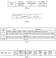
FIG. 5 is a schematic diagram illustrating a format of a secondary channel field indication field according to an embodiment of the disclosure. -
FIG. 6 is a schematic diagram illustrating an indication specification of a secondary channel indication field according to an embodiment of the disclosure. -
FIG. 7 is a schematic diagram illustrating a format of a channel switching indication field according to an embodiment. -
FIG. 8 is a flowchart illustrating a channel switching method according to an embodiment of the disclosure. -
FIG. 9 is a block diagram illustrating a channel switching apparatus according to an embodiment of the disclosure. -
FIG. 10 is a block diagram illustrating a channel switching apparatus according to an embodiment of the disclosure. -
FIG. 11 is a schematic diagram illustrating a communication device according to an embodiment of the disclosure. - To illustrate the purposes, the solutions and the advantages of the present disclosure more clearly, the embodiments of the disclosure are further described below with reference to the accompanying drawings.
-
FIG. 1 is a schematic diagram illustrating a communication system according to an embodiment. The communication system may include an access point (AP) 120 and astation 140. - The
AP 120 is configured to provide a wireless access function. TheAP 120 may be a wireless router, a base station with the Wi-Fi function and so on. OneAP 120 may accessmultiple stations 140. - The
station 140 is configured to access theAP 120. Thestation 140 may be a mobile phone, a tablet, a notebook computer, an electronic book, a machine and so on. - The above communication system may be an institute of electrical and electronics engineers (IEEE) 802.11 a/b/g/n/ac/ax/be communication network. In the embodiments of the disclosure, for example, the communication system is IEEE 802. 11 be communication network.
- A channel switching typically occurs in a situation where a quality of a current channel is poor or a wider channel is required for a communication. Typically, a channel switching frame sent from the AP to the station (STA) is configured to instruct the STA to switch a channel for the communication. As illustrated in
FIG. 2 , the channel switching frame 200 has a format as shown in the figure. The channel switching frame includes a channel switching field (Channel Switch Announcement element) 210 of 5 bytes, aCategory field 220 of 1 byte, a SpectrumManagement Action field 230 of 1 byte, a secondary channel indication field (Secondary Channel Offset element) 240 of 0 or 3 bytes, a Mesh Channel SwitchParameters element field 250 of 0 or 8 bytes, a Wide Bandwidth ChannelSwitch element field 260 of 0 or 5 bytes and a New Transmit PowerEnvelop element field 270 of variable bytes. A format of the channel switchannouncement element field 210 is shown inFIG. 2 , including a property field (Element ID) 221, aLength field 222, a switching restriction indication field (Channel Switch Mode) 223, a channel indication field (New Channel Number) 224 and a timing field (Channel Switch Count) 225. Each of theElement ID field 221, theLength field 222, the ChannelSwitch Mode field 223, the NewChannel Number field 224 and the ChannelSwitch Count field 225 occupies 1 byte. In an existing standard, the channel switching frame is sent under a link/frequency band, which indicates that the communication between the AP and the STA is switched from one channel to another channel. - The multi-link refers to that a device performs data transmissions simultaneously on at least two frequency bands. The at least two frequency bands include at least two of the 2.4GHz frequency band, the 5.8GHz frequency band and the 6-7 frequency band. For example, the device performs data transmissions simultaneously under the 2.4GHz frequency band, the 5.8GHz frequency band and the 6-7 frequency band. When data with the same content is transmitted under multiple links, a multi-link mode may improve a throughout of an entire system. When data with different contents is transmitted under multiple links, the multi-link mode may improve a success rate of sending/receiving the data.
- Under the 2.4GHz frequency band, there are fourteen channels. For example, a frequency range of the 2.4GHz frequency band is 2.4GHz-2.4835GHz. Under the 2.4GHz frequency band, a channel 01 has a central frequency of 2412MHz and a frequency range of 2401MHz-2423MHz, a channel 02 has a central frequency of 2417MHz and a frequency range of 2406MHz-2428MHz, and so on.
- In IEEE 802.11, the device may perform the communication under multiple links. According to an existing protocol standard, the channel switching frame needs to be sent in multiple channels to perform the channel switching under the multiple links. For example, the channel switching frame is sent simultaneously in multiple channels, or the channel switching frame is sent in each channel respectively, both of the above two channel switching modes under the multiple links may cause a huge of signaling overhead.
- In the embodiments of the disclosure, a channel switching method is provided, which may provide a channel switching mechanism under multiple links, thus improving an effective utilization of frequency spectrum.
FIG. 3 is a flowchart of a channel switching method according to an embodiment of the disclosure. For example, the method is applied in a first device, and the first device may be implemented as an AP. As illustrated inFIG. 3 , the method includes the following. - At
block 301, a multi-link channel switching frame is generated under a link. The multi-link channel switching frame is configured to indicate that a channel switching is performed under multiple links. - The multiple links are configured to indicate that the first device supports performing data transmissions simultaneously on at least two frequency bands.
- For example, a format of the multi-link channel switching frame is shown in
FIG. 4 . The multi-link channel switching frame includes aCategory field 410, a Spectrummanagement action field 420, a Channel switch announcement field 430 and a Secondary channel offset (SCO) element field 440. The Spectrummanagement action field 420 is configured to indicate that the current frame is a new action frame, i.e., the current frame is a multi-link channel switching frame. The Channel switch announcement field 430 is configured to configure a channel switching mode. The SCO field 440 is configured to indicate an inclusion situation of a secondary channel in a frequency band. - In some embodiments, the multi-link channel switching frame includes a frequency band indication field and a channel indication field. The frequency band indication field is configured to indicate a target frequency band of the channel switching, and the channel indication field is configured to indicate a target channel of the channel switching in the target frequency band. In some embodiments, the frequency band indication field and the channel indication field are in the Channel switch announcement field.
- The first device is configured with a correspondence between a link identification and the target frequency band, and the frequency band indication field is configured to indicate the target frequency band with the link identification. For example, the
link identification 1 corresponds to the 2.4GHz frequency band, and thelink identification 2 corresponds to the 5GHz frequency band. For example, if the multi-link channel switching frame includes thelink identification 1 and the channel indication field 02 corresponding to thelink identification 1, it represents that the multi-link channel switching frame indicates that the channel is switched to the channel 02 in the 2.4GHz frequency band for the communication. For example, the multi-link channel switching frame includes the Link1 field and the New Channel number field corresponding to the Link1, the Link2 field and the New Channel number field corresponding to the Link2. The Link1 field corresponds to the 2.4GHz frequency band, and the Link2 field corresponds to the 5GHz frequency band. The New Channel number field corresponding to the Link1 has a value of 02, and the New Channel number field corresponding to the Link2 has a value of 05. It indicates that the channel is switched to the channel 02 in the 2.4GHz frequency band, and the channel is switched to the channel 05 in the 5GHz frequency band. - In some embodiments, the multi-link channel switching frame further includes a timing field. The timing field is configured to indicate a switching time point of switching to the target channel in the target frequency band. The timing field is assigned a value based on a number of target beacon transmission times (TBTTs). The timing field has the same value or different values for multiple links. In some embodiments, a time point of a TBTT establishing an initial link is configures as a reference, timing is conducted with the number of TBTTs. In the embodiment of the disclosure, for example, the timing field has different values for different frequency bands. For example, for Link1, the Channel switch count field is used as the timing field and has a value of 12. Link1 corresponds to the 2.4GHz frequency band. In the 2.4GHz frequency band, the channel switching is started at the 12th TBTT after the establishment of the initial link.
- The multi-link channel switching frame is generated under one link of the multiple links. In some embodiments, the link is a link of establishing an initial association between the first device and the second device. For example, the initial association is established between the second device and the first device through the 2.4GHz frequency band, the multi-link channel switching frame is generated under the 2.4GHz frequency band.
- In some embodiments, the multi-link channel switching frame further includes a secondary channel indication field. The secondary channel indication field is configured to indicate an inclusion situation of a secondary channel in the target frequency band. The new channel switched to in the link may include a secondary channel, and the SCO field exists to indicate whether the secondary channel exists in each link. When the secondary channel exists, a secondary channel field indication field is added in the Channel switch announcement field to indicate whether the secondary field exists in each link. The format of the secondary channel field indication field is shown in
FIG. 5 , including anElement ID field 510 of 1 byte, aLength field 520 of 1 byte, and aSCO field 530 of 1 byte. An indication specification of theSCO field 530 is illustrated inFIG. 6 . When value = "0" and name = "SCN-no secondary channel", it indicates there is no secondary channel, and the description information is "Indicates that no Secondary channel is present", which means that there is no secondary channel for the current primary channel. When value = "1" and name = "SCN-Secondary Channel Above", it indicates a frequency range of the secondary channel is an upper frequency range, and the description information is "Indicates that the secondary channel is above the primary channel", which means that the frequency range of the secondary channel is a frequency range after the frequency range of the current primary channel. When value = "3" and name = "SCN-Secondary Channel Below", it indicates a frequency range of the secondary channel is a lower frequency range, and the description information is "Indicates that the secondary channel is below the primary channel", which means that the frequency range of the secondary channel is a frequency range before the frequency range of the current primary channel. For example, the current frequency spectrum is 5120-5180, the frequency range of the working bandwidth of the primary channel is 5140-5160, when value = "I", it indicates that the frequency range of the secondary channel is 5160-5180, when value = "3", it indicates that the frequency range of the secondary channel is 5120-5140. In some embodiments, value = "2" and value = "4-255" are reserved fields. - In some embodiments, the multi-link channel switching frame further includes a switching restriction indication field (Channel Switch mode). The Channel Switch mode field is configured to indicate a condition restriction of the channel switching. In some embodiments, the condition restriction of the channel switching may be different or the same for the channel switching processes in different links. Each link corresponds to one Channel Switch mode field, to indicate the condition restriction of the channel switching under the link.
- For example, in response to the switching restriction indication field having a first value, the switching restriction indication field is configured to indicate that the channel switching is performed in a basic service set (BSS) networking mode. In response to the switching restriction indication field having a second value, the switching restriction indication field is configured to indicate that the channel switching is performed in an independent basic service set (IBSS) networking mode. For example, the first value is 1, the second value is 0. The switching restriction indication field is assigned 1, it indicates that under the Link1, when performing the channel switching, the switching is performed in the BSS networking mode.
- At
block 302, the multi-link channel switching frame is sent to the second device under the link. - In some embodiments, the link is the link of establishing the initial association between the second device and the first device. That is, the first device sends the multi-link channel switching frame to the second device under the link after generating the multi-link channel switching frame under the link.
- In some embodiments, the multi-link channel switching frame may be carried in indication information to be sent.
- For example, with the format of the multi-link channel switching frame illustrated in
FIG. 4 , the Channel switch announcement field is shown inFIG. 7 , including an Element ID field 710 (for indicating a property of information element, IE), aLength field 720, aSCO field 730, a ChannelSwitch mode field 740, a frequencyband indication field 750, a NewChannel number field 760 and a Channelswitch count field 770. There may be multiple groups of the ChannelSwitch mode field 740, the frequencyband indication field 750, the NewChannel number field 760 and the Channelswitch count field 770 according to different number of the multiple links. That is, for each link, there is a group of the ChannelSwitch mode field 740, the frequencyband indication field 750, the NewChannel number field 760 and the Channelswitch count field 770. - In conclusion, with the channel switching method according to the embodiment of the disclosure, by setting a multi-link channel switching frame, a channel switching mechanism under multiple links is defined, such that the sending of a channel switching frame under each of the multiple links is avoided, thus simplifying transmission of signaling and improving an effective utilization of frequency spectrum.
- In an alternative embodiment, after receiving the multi-link channel switching frame, the second device performs the channel switching based on the multi-link channel switching frame. The second device may be implemented as a STA.
FIG. 8 is a flowchart illustrating a channel switching method according to an embodiment of the disclosure. As illustrated inFIG. 8 , the method includes the following. - At block 801, the first device generates a multi-link channel switching frame is generated under a link. The multi-link channel switching frame is configured to indicate that a channel switching is performed under multiple links.
- In some embodiments, the multi-link channel switching frame includes a frequency band indication field and a channel indication field, the frequency band indication field is configured to indicate a target frequency band of the channel switching, and the channel indication field is configured to indicate a target channel of the channel switching.
- The first device is configured with a correspondence between a link identification and the target frequency band, and the frequency band indication field comprises the link identification.
- In some embodiments, the multi-link channel switching frame further includes a timing field, and the timing field is configured to indicate a switching time point of switching to the target channel in the target frequency band. The timing field is assigned a value based on a number of target beacon transmission times (TBTTs). The timing field may be the same or different for multiple links.
- The multi-link channel switching frame is generated under one of the multiple links. In some embodiments, the link is a link of establishing an initial association between the second device and the first device.
- At block 802, the first device sends the multi-link channel switching frame to the second device under the link.
- In some embodiments, the link is the link of establishing the initial association between the second device and the first device. That is, the first device sends the multi-link channel switching frame to the second device under the link after generating the multi-link channel switching frame under the link.
- At
block 803, the second device receives the multi-link channel switching frame under one link. - Alternatively, the link is the link of establishing the initial association between the second device and the first device. The first device sends the multi-link channel switching frame to the second device under the link, and the second device receives the multi-link channel switching frame sent from the first device under the link.
- At
block 804, the second device performs a channel switching based on the multi-link channel switching frame. - In some embodiments, the multi-link channel switching frame includes a frequency band indication field and a channel indication field, the frequency band indication field is configured to indicate a target frequency band of the channel switching, and the channel indication field is configured to indicate a target channel of the channel switching. When the second device performs the channel switching based on the multi-link channel switching frame, the channel is switched to the target channel in the target frequency band for the communication.
- In some embodiments, the second device is configured with a correspondence between a link identification and the target frequency band, and the frequency band indication field includes the link identification. The second device determines the target frequency band in which the channel switching is performed based on the link identification. For example, the
link identification 1 corresponds to the 2.4GHz frequency band, and thelink identification 2 corresponds to the 5GHz frequency band. For example, if the multi-link channel switching frame includes thelink identification 1 and the channel indication field 02 corresponding to thelink identification 1, it represents that the multi-link channel switching frame indicates that the channel is switched to the channel 02 in the 2.4GHz frequency band for the communication, such that the second device switches to the channel 02 in the 2.4GHz frequency band for the communication. - In some embodiments, the multi-link channel switching frame further includes a timing field, and the timing field is configured to indicate a switching time point of the channel switching. The second device performs the channel switching in response to the switching time point being up. The timing field is assigned a value based on a number of target beacon transmission times (TBTTs). The timing field may be the same or different for multiple links. In some embodiments, a time point of a TBTT establishing an initial link is configures as a reference, timing is conducted with the number of TBTTs.
- In some embodiments, the multi-link channel switching frame further includes a secondary channel indication field. The secondary channel indication field is configured to indicate an inclusion situation of a secondary channel in the target frequency band. The new channel switched to in the link may include a secondary channel, and the SCO field exists to indicate whether the secondary channel exists in each link. When the secondary channel exists, a secondary channel field indication field is added in the Channel switch announcement field to indicate whether the secondary field exists in each link, and indicate a frequency range of the secondary channel.
- In some embodiments, the multi-link channel switching frame further includes a switching restriction indication field (Channel Switch mode). The Channel Switch mode field is configured to indicate a condition restriction of the channel switching. In some embodiments, the condition restriction of the channel switching may be different or the same for the channel switching processes in different links. Each link corresponds to one Channel Switch mode field, to indicate the condition restriction of the channel switching under the link.
- The second device performs the channel switching in response to the communication meeting the condition restriction.
- For example, in response to the switching restriction indication field having a first value, the switching restriction indication field is configured to indicate that the channel switching is performed in a basic service set (BSS) networking mode, such that the second device performs the channel switching in the BSS networking mode. In response to the switching restriction indication field having a second value, the switching restriction indication field is configured to indicate that the channel switching is performed in an independent basic service set (IBSS) networking mode, such that the second device performs the channel switching in the IBSS networking mode.
- In conclusion, with the channel switching method according to the embodiment of the disclosure, by setting a multi-link channel switching frame, a channel switching mechanism under multiple links is defined, such that the sending of a channel switching frame under each of the multiple links is avoided, thus simplifying transmission of signaling and improving an effective utilization of frequency spectrum.
-
FIG. 9 is a block diagram illustrating a channel switching apparatus according to an embodiment of the disclosure. For example, the apparatus is applied in a first device. As illustrated inFIG. 9 , the apparatus includes aprocessing module 910. - The processing module 901 is configured to generate a multi-link channel switching frame under a link. The multi-link channel switching frame is configured to indicate that a channel switching is performed under multiple links, and the multiple links are configured to indicate that the first device supports performing data transmissions simultaneously on at least two frequency bands.
- In an alternative embodiment, the apparatus further includes a sending
module 920 configured to send the multi-link channel switching frame to a second device under the link. - In an alternative embodiment, the multi-link channel switching frame includes a frequency band indication field and a channel indication field. The frequency band indication field is configured to indicate a target frequency band of the channel switching, and the channel indication field is configured to indicate a target channel of the channel switching in the target frequency band.
- In an alternative embodiment, the first device is configured with a correspondence between a link identification and the target frequency band, and the frequency band indication field is configured to indicate the target frequency band with the link identification.
- In an alternative embodiment, the multi-link channel switching frame further includes a timing field. The timing field is configured to indicate a switching time point of the channel switching.
- In an alternative embodiment, the timing field is assigned a value based on a number of target beacon transmission times (TBTTs).
- In an alternative embodiment, the link is used to establish an initial association between the first device and the second device.
- In an alternative embodiment, the multi-link channel switching frame further includes a secondary channel indication field. The secondary channel indication field is configured to indicate an inclusion situation of a secondary channel in the target frequency band.
- In an alternative embodiment, the multi-link channel switching frame further includes a switching restriction indication field. The switching restriction indication field is configured to indicate a condition restriction of the channel switching.
- In an alternative embodiment, the switching restriction indication field is configured to indicate that the channel switching is performed in a basic service set (BSS) networking mode in response to the switching restriction indication field having a first value; the switching restriction indication field is configured to indicate that the channel switching is performed in an independent basic service set (IBSS) networking mode in response to the switching restriction indication field having a second value.
-
FIG. 10 is a block diagram illustrating a channel switching apparatus according to an embodiment of the disclosure. For example, the apparatus is applied in a second device. As illustrated inFIG. 10 , the apparatus includes areceiving module 1010. - The
receiving module 1010 is configured to receive a multi-link channel switching frame under a link. The multi-link channel switching frame is configured to indicate that a channel switching is performed under multiple links, and the multiple links are configured to indicate that the second device supports performing data transmissions simultaneously on at least two frequency bands. - In an alternative embodiment, the multi-link channel switching frame includes a frequency band indication field and a channel indication field, the frequency band indication field is configured to indicate a target frequency band of the channel switching, and the channel indication field is configured to indicate a target channel of the channel switching.
- The apparatus further includes a
processing module 1020 configured to switch to the target channel in the target frequency band for a communication according to the multi-link channel switching frame. - In an alternative embodiment, the second device is configured with a correspondence between a link identification and the target frequency band, and the frequency band indication field comprises the link identification.
- The
processing module 1020 is further configured to determine the target frequency band according to the link identification. - In an alternative embodiment, the multi-link channel switching frame further comprises a timing field, and the timing field is configured to indicate a switching time point of the channel switching.
- The apparatus further includes a
processing module 1020 configured to perform the channel switching in response to the switching time point being up. - In an alternative embodiment, the timing field is assigned a value based on a number of target beacon transmission times (TBTTs).
- In an alternative embodiment, the link is used to establish an initial association between the first device and the second device.
- In an alternative embodiment, the multi-link channel switching frame further includes a secondary channel indication field, and the secondary channel indication field is configured to indicate an inclusion situation of a secondary channel in the target frequency band.
- In an alternative embodiment, the multi-link channel switching frame further comprises a switching restriction indication field, and the switching restriction indication field is configured to indicate a condition restriction of the channel switching.
- The apparatus further includes a
processing module 1020 configured to perform the channel switching in response to a communication meeting the condition restriction. - In conclusion, with the channel switching apparatus according to the embodiment of the disclosure, by setting a multi-link channel switching frame, a channel switching mechanism under multiple links is defined, such that the sending of a channel switching frame under each of the multiple links is avoided, thus simplifying transmission of signaling and improving an effective utilization of frequency spectrum.
-
FIG. 11 is a schematic diagram illustrating a communication device 1100 (the first device or the second device) according to an embodiment of the disclosure. The second device includes aprocessor 1101, areceiver 1102, atransmitter 1103, amemory 1104 and abus 1105. - The
processor 1101 includes one or more processing cores. Theprocessor 1101 executes software programs and modules to implement various functions and information processing. - The
receiver 1102 and thetransmitter 1103 may be one communication component. The communication component may be a communication chip. - The
memory 1104 is coupled to theprocessor 1101 via thebus 1105. - The
memory 1104 may be configured to store at least one instruction. Theprocessor 1101 is configured to execute the at least one instruction to implement each step of the above method embodiments. - Further, the
memory 1104 may be implemented by any type of temporary or non-temporary storage devices or their combination. The temporary or non-temporary storage devices include but are not limited to a magnetic disk or an optical disk, an electrically erasable programmable read-only memory (EEPROM), an electrically programmable read-only memory (EPROM), a static random access memory (SRAM), a read-only memory (ROM), a magnetic memory, a flash memory, a programmable read-only memory (PROM). - A non-transitory computer-readable storage medium is provided. When instructions stored in the non-transitory computer-readable storage medium are executed by a processor of a wireless communication device, the wireless communication device may perform the above mentioned channel switching method.
- The embodiment of the disclosure further provides a channel switching system. The system includes a first device and a second device.
- The first device includes the channel switching apparatus provided in the embodiment described with reference to
FIG. 9 . - The second device includes the channel switching apparatus provided in the embodiment described with reference to
FIG. 10 . - The embodiment of the disclosure further provides a computer-readable storage medium. The computer-readable storage medium is stored with at least one instruction, at least one segment of programs, a set of codes or instructions. The at least one instruction, the at least one segment of programs, the set of codes or instructions is loaded or executed by a processor to perform each step executed by the wireless communication device in the channel switching method according to the above method embodiments of the disclosure.
- It should be understood that references herein to "a plurality" means two or more. "And/or", which describes an association relationship of associated objects, means that there can be three kinds of relationships, for example, A and/or B, which can mean that A exists alone, A and B exist at the same time, and B exists alone. The character "/" generally indicates that the associated objects are an "or" relationship.
- Other implementations of the present disclosure will readily occur to those skilled in the art upon consideration of the specification and practice of the invention disclosed herein. The disclosure is intended to cover any variations, uses, or adaptations of the disclosure that follow the general principles of the disclosure and include common general knowledge or techniques in the technical field not disclosed by the disclosure. The specification and examples are to be regarded as exemplary only, the true scope and spirit of the disclosure being indicated by the following claims.
- It should be understood that the disclosure is not limited to the precise structure described above and shown in the drawings, and various modifications and changes may be made without departing from its scope. The scope of the present disclosure is only limited by the appended claims.
Claims (23)
- A channel switching method, applied in a first device, comprising:
generating a multi-link channel switching frame under a link, wherein the multi-link channel switching frame is configured to indicate a channel switching to be performed under multiple links, and wherein the multiple links are configured to indicate that the first device supports performing data transmissions simultaneously on at least two frequency bands. - The method of claim 1, further comprising:
sending the multi-link channel switching frame to a second device under the link. - The method of claim 1, wherein,
the multi-link channel switching frame comprises a frequency band indication field and a channel indication field, wherein the frequency band indication field is configured to indicate a target frequency band of the channel switching, and the channel indication field is configured to indicate a target channel of the channel switching in the target frequency band. - The method of claim 3, wherein,
the first device is configured with a correspondence between a link identification and the target frequency band, and the frequency band indication field is configured to indicate the target frequency band with the link identification. - The method of any of claims 1-4, wherein,
the multi-link channel switching frame further comprises a timing field, wherein the timing field is configured to indicate a switching time point of the channel switching. - The method of claim 5, wherein,
the timing field is assigned a value based on a number of target beacon transmission times (TBTTs). - The method of any of claims 1-4, wherein,
the link is configured to establish an initial association between the first device and the second device. - The method of any of claims 2-4, wherein,
the multi-link channel switching frame further comprises a secondary channel indication field, wherein the secondary channel indication field is configured to indicate an inclusion situation of a secondary channel in the target frequency band. - The method of any of claims 1-4, wherein,
the multi-link channel switching frame further comprises a switching restriction indication field, wherein the switching restriction indication field is configured to indicate a condition restriction of the channel switching. - The method of claim 9, wherein,the switching restriction indication field is configured to indicate that the channel switching is performed in a basic service set (BSS) networking mode in response to the switching restriction indication field having a first value;the switching restriction indication field is configured to indicate that the channel switching is performed in an independent basic service set (IBSS) networking mode in response to the switching restriction indication field having a second value.
- A channel switching method, applied in a second device, comprising:
receiving a multi-link channel switching frame under a link, wherein the multi-link channel switching frame is configured to indicate that a channel switching is performed under multiple links, and wherein the multiple links are configured to indicate that the second device supports performing data transmissions simultaneously on at least two frequency bands. - The method of claim 11, wherein, the multi-link channel switching frame comprises a frequency band indication field and a channel indication field, wherein the frequency band indication field is configured to indicate a target frequency band of the channel switching, and the channel indication field is configured to indicate a target channel of the channel switching;
the method further comprises:
switching to the target channel in the target frequency band for a communication according to the multi-link channel switching frame. - The method of claim 12, wherein, the second device is configured with a correspondence between a link identification and the target frequency band, and the frequency band indication field comprises the link identification;
the method further comprises:
determining the target frequency band according to the link identification. - The method of any of claims 11-13, wherein, the multi-link channel switching frame further comprises a timing field, wherein the timing field is configured to indicate a switching time point of the channel switching;
the method further comprises:
performing the channel switching in response to the switching time point being up. - The method of claim 14, wherein,
the timing field is assigned a value based on a number of target beacon transmission times (TBTTs). - The method of any of claims 11-13, wherein the link is configured to establish an initial association between the first device and the second device.
- The method of claim 12 or 13, wherein, the multi-link channel switching frame further comprises a secondary channel indication field, wherein the secondary channel indication field is configured to indicate an inclusion situation of a secondary channel in the target frequency band.
- The method of any of claims 11-13, wherein, the multi-link channel switching frame further comprises a switching restriction indication field, wherein the switching restriction indication field is configured to indicate a condition restriction of the channel switching; and
the method further comprises:
performing the channel switching in response to a communication meeting the condition restriction. - A channel switching apparatus, applied in a first device, comprising:
a processing module, configured to generate a multi-link channel switching frame under a link, wherein the multi-link channel switching frame is configured to indicate that a channel switching is performed under multiple links, wherein the multiple links are configured to indicate that the first device supports performing data transmissions simultaneously on at least two frequency bands. - A channel switching apparatus, applied in a second device, comprising:
a receiving module, configured to receive a multi-link channel switching frame under a link, wherein the multi-link channel switching frame is configured to indicate that a channel switching is performed under multiple links, wherein the multiple links are configured to indicate that the second device supports performing data transmissions simultaneously on at least two frequency bands. - A wireless communication device, comprising:a processor; anda transceiver coupled to the processor;wherein the processor is configured to load and execute executable instructions to perform the channel switching method according to any of claims 1-10.
- A wireless communication device, comprising:a processor;a transceiver coupled to the processor;wherein the processor is configured to load and execute executable instructions to perform the channel switching method according to any of claims 11-18.
- A computer-readable storage medium stored with at least one instruction, at least one segment of programs, a set of codes or instructions, wherein the at least one instruction, the at least one segment of programs, the set of codes or instructions is loaded or executed by a processor to perform the channel switching method according to any of claims 1-18.
Applications Claiming Priority (1)
| Application Number | Priority Date | Filing Date | Title |
|---|---|---|---|
| PCT/CN2020/078378 WO2021179111A1 (en) | 2020-03-09 | 2020-03-09 | Channel switching method, apparatus, device, and readable storage medium |
Publications (3)
| Publication Number | Publication Date |
|---|---|
| EP4120646A1 true EP4120646A1 (en) | 2023-01-18 |
| EP4120646A4 EP4120646A4 (en) | 2023-11-08 |
| EP4120646B1 EP4120646B1 (en) | 2025-10-01 |
Family
ID=77671166
Family Applications (1)
| Application Number | Title | Priority Date | Filing Date |
|---|---|---|---|
| EP20923867.4A Active EP4120646B1 (en) | 2020-03-09 | 2020-03-09 | Channel switching method, apparatus and device |
Country Status (5)
| Country | Link |
|---|---|
| US (1) | US12396048B2 (en) |
| EP (1) | EP4120646B1 (en) |
| CN (1) | CN113632430B (en) |
| ES (1) | ES3057107T3 (en) |
| WO (1) | WO2021179111A1 (en) |
Cited By (1)
| Publication number | Priority date | Publication date | Assignee | Title |
|---|---|---|---|---|
| WO2024154966A1 (en) * | 2023-01-20 | 2024-07-25 | 주식회사 윌러스표준기술연구소 | Wireless communication method using multiple links, and wireless communication terminal using same |
Families Citing this family (3)
| Publication number | Priority date | Publication date | Assignee | Title |
|---|---|---|---|---|
| CN115474293A (en) * | 2022-08-08 | 2022-12-13 | 四川华能嘉陵江水电有限责任公司 | Method for establishing direct link by multilink equipment |
| KR20250164282A (en) * | 2023-03-22 | 2025-11-24 | 광동 오포 모바일 텔레커뮤니케이션즈 코포레이션 리미티드 | Channel operation methods, devices, communication devices and storage media |
| WO2026016127A1 (en) * | 2024-07-18 | 2026-01-22 | Oppo广东移动通信有限公司 | Communication method, apparatus and device, and medium and program product |
Family Cites Families (23)
| Publication number | Priority date | Publication date | Assignee | Title |
|---|---|---|---|---|
| US7177308B2 (en) | 1998-07-22 | 2007-02-13 | Synchrodyne Networks, Inc. | Switching methods with common time reference and plurality of time frame durations |
| US7352728B2 (en) * | 2002-03-07 | 2008-04-01 | Koninklijke Philips Electronics N.V. | Fast channel switching scheme for IEEE 802.11 WLANs |
| FR2902589A1 (en) | 2006-06-20 | 2007-12-21 | France Telecom | COMMUNICATION METHOD, TRANSCEIVER AND RECEIVER STATIONS, AND COMPUTER PROGRAMS THEREOF |
| CN101621836B (en) * | 2008-06-30 | 2012-09-05 | 华为技术有限公司 | Method for channel switching in Mesh network, device and mesh network |
| KR101584873B1 (en) * | 2010-11-12 | 2016-01-13 | 인터디지탈 패튼 홀딩스, 인크 | Method and apparatus for performing channel aggregation and medium access control retransmission |
| FR2979784A1 (en) * | 2011-09-02 | 2013-03-08 | France Telecom | CHANNEL SELECTION METHOD, WIFI EQUIPMENT AND CORRESPONDING COMPUTER PROGRAM |
| US10021599B2 (en) * | 2011-09-20 | 2018-07-10 | Qualcomm Incorporated | Channel and bandwidth switch procedures for wireless networks |
| US9451518B2 (en) * | 2013-03-08 | 2016-09-20 | Qualcomm Incorporated | Channel management in a Wi-Fi device in a multi-channel concurrent environment |
| CN103152777B (en) * | 2013-03-11 | 2016-03-09 | 东莞宇龙通信科技有限公司 | Communicator and frequency band switching method |
| CN104349406B (en) * | 2013-07-24 | 2018-08-14 | 华为技术有限公司 | A kind of channel switching method and access point |
| JP6040907B2 (en) | 2013-10-15 | 2016-12-07 | 日立金属株式会社 | Network relay system and switch device |
| US20200396568A1 (en) * | 2014-08-19 | 2020-12-17 | Po-Kai Huang | Group addressed data delivery |
| US10856203B2 (en) * | 2017-01-19 | 2020-12-01 | Qualcomm Incorporated | Signaling for link aggregation setup and reconfiguration |
| CN109309937B (en) * | 2017-07-26 | 2020-07-07 | 华为技术有限公司 | Method, controller, network device and storage medium for switching access point |
| US10560940B2 (en) * | 2017-11-10 | 2020-02-11 | Nokia Solutions And Networks Oy | Intelligent traffic steering over optimal paths using multiple access technologies |
| US10455469B2 (en) * | 2017-12-28 | 2019-10-22 | Intel Corporation | Radar channel switching for Wi-Fi virtual reality |
| WO2020032639A1 (en) * | 2018-08-10 | 2020-02-13 | 엘지전자 주식회사 | Method and device for transmitting information for operating station in wireless local area network system supporting multiple bands |
| CN110167201B (en) | 2018-09-30 | 2022-05-17 | 腾讯科技(深圳)有限公司 | A data transmission method, related device and system |
| US11711848B2 (en) * | 2019-10-08 | 2023-07-25 | Intel Corporation | Link switch parameters |
| US12389493B2 (en) * | 2019-10-29 | 2025-08-12 | Lg Electronics Inc. | Link deactivation in multi-link |
| US11723113B2 (en) * | 2020-01-04 | 2023-08-08 | Nxp Usa, Inc. | Apparatus and method for enabling and disabling links in multi-link communication systems |
| US11601999B2 (en) * | 2020-01-04 | 2023-03-07 | Nxp Usa, Inc. | Apparatus and method for multi-link management |
| US11595884B2 (en) * | 2020-02-12 | 2023-02-28 | Mediatek Singapore Pte. Ltd. | Apparatus and methods for EHT multi-link BBS parameter update |
-
2020
- 2020-03-09 US US17/909,914 patent/US12396048B2/en active Active
- 2020-03-09 EP EP20923867.4A patent/EP4120646B1/en active Active
- 2020-03-09 CN CN202080000541.8A patent/CN113632430B/en active Active
- 2020-03-09 WO PCT/CN2020/078378 patent/WO2021179111A1/en not_active Ceased
- 2020-03-09 ES ES20923867T patent/ES3057107T3/en active Active
Cited By (1)
| Publication number | Priority date | Publication date | Assignee | Title |
|---|---|---|---|---|
| WO2024154966A1 (en) * | 2023-01-20 | 2024-07-25 | 주식회사 윌러스표준기술연구소 | Wireless communication method using multiple links, and wireless communication terminal using same |
Also Published As
| Publication number | Publication date |
|---|---|
| ES3057107T3 (en) | 2026-02-26 |
| CN113632430B (en) | 2024-08-16 |
| EP4120646B1 (en) | 2025-10-01 |
| WO2021179111A1 (en) | 2021-09-16 |
| CN113632430A (en) | 2021-11-09 |
| EP4120646A4 (en) | 2023-11-08 |
| US12396048B2 (en) | 2025-08-19 |
| US20230103595A1 (en) | 2023-04-06 |
Similar Documents
| Publication | Publication Date | Title |
|---|---|---|
| US11924823B2 (en) | Multi-link device association and reassociation | |
| US20230180323A1 (en) | Method, apparatus, and system for setting up direct link, and method and apparatus for sending wireless local area network frame | |
| US20240333429A1 (en) | Communication method and apparatus applied to multi-link device in wireless local area network | |
| EP4203595A1 (en) | Multi-link low-latency communication method and apparatus, and storage medium and electronic apparatus | |
| EP4120646B1 (en) | Channel switching method, apparatus and device | |
| JP2023521512A (en) | Link processing method, multilink device and computer readable storage medium | |
| CN114158140A (en) | Multi-link establishment method and communication device in wireless communication system | |
| CN112218336A (en) | Multilink communication method and device | |
| EP4178266A1 (en) | Communication method, apparatus, and system in wireless local area network | |
| US12284602B2 (en) | AID allocation method for multi-link device and related apparatus | |
| WO2021244490A1 (en) | Link selection method and apparatus, and computer readable storage medium | |
| EP4346315A1 (en) | Buffer status reporting for triggered transmission opportunity sharing | |
| CN111148158B (en) | Communication method and device | |
| EP3975657A1 (en) | Data transmission method, apparatus, and device, and storage medium | |
| JP2025096276A (en) | Data transmission method and device | |
| US9622115B2 (en) | Channel negotiation method, device, and system | |
| CN118102423A (en) | Information indication method and device | |
| WO2024086193A1 (en) | Transmission techniques for multi-ap transmission | |
| US12408183B2 (en) | Buffered groupcast downlink data notification method, and terminal and access point device | |
| CN115918242B (en) | Communication methods and devices | |
| EP4723737A1 (en) | Sharing access point, terminal, and shared access point | |
| CN113383503A (en) | Time synchronization method, device, terminal, access point equipment and storage medium | |
| EP4679890A1 (en) | Terminal device, sharing access point, shared access point, and wireless communication method | |
| CN113747421B (en) | Method, equipment and system for controlling terminal regression under mobile network sharing mechanism | |
| WO2026013724A1 (en) | Access point and terminal device |
Legal Events
| Date | Code | Title | Description |
|---|---|---|---|
| STAA | Information on the status of an ep patent application or granted ep patent |
Free format text: STATUS: THE INTERNATIONAL PUBLICATION HAS BEEN MADE |
|
| PUAI | Public reference made under article 153(3) epc to a published international application that has entered the european phase |
Free format text: ORIGINAL CODE: 0009012 |
|
| STAA | Information on the status of an ep patent application or granted ep patent |
Free format text: STATUS: REQUEST FOR EXAMINATION WAS MADE |
|
| 17P | Request for examination filed |
Effective date: 20220928 |
|
| AK | Designated contracting states |
Kind code of ref document: A1 Designated state(s): AL AT BE BG CH CY CZ DE DK EE ES FI FR GB GR HR HU IE IS IT LI LT LU LV MC MK MT NL NO PL PT RO RS SE SI SK SM TR |
|
| DAV | Request for validation of the european patent (deleted) | ||
| DAX | Request for extension of the european patent (deleted) | ||
| REG | Reference to a national code |
Ref country code: DE Ref legal event code: R079 Free format text: PREVIOUS MAIN CLASS: H04L0029040000 Ipc: H04W0036280000 Ref document number: 602020059954 Country of ref document: DE |
|
| A4 | Supplementary search report drawn up and despatched |
Effective date: 20231011 |
|
| RIC1 | Information provided on ipc code assigned before grant |
Ipc: H04W 76/15 20180101ALI20231005BHEP Ipc: H04W 72/0453 20230101ALI20231005BHEP Ipc: H04W 36/28 20090101AFI20231005BHEP |
|
| STAA | Information on the status of an ep patent application or granted ep patent |
Free format text: STATUS: EXAMINATION IS IN PROGRESS |
|
| 17Q | First examination report despatched |
Effective date: 20241217 |
|
| GRAP | Despatch of communication of intention to grant a patent |
Free format text: ORIGINAL CODE: EPIDOSNIGR1 |
|
| STAA | Information on the status of an ep patent application or granted ep patent |
Free format text: STATUS: GRANT OF PATENT IS INTENDED |
|
| INTG | Intention to grant announced |
Effective date: 20250709 |
|
| GRAS | Grant fee paid |
Free format text: ORIGINAL CODE: EPIDOSNIGR3 |
|
| P01 | Opt-out of the competence of the unified patent court (upc) registered |
Free format text: CASE NUMBER: UPC_APP_0691_4120646/2025 Effective date: 20250721 |
|
| GRAA | (expected) grant |
Free format text: ORIGINAL CODE: 0009210 |
|
| STAA | Information on the status of an ep patent application or granted ep patent |
Free format text: STATUS: THE PATENT HAS BEEN GRANTED |
|
| P02 | Opt-out of the competence of the unified patent court (upc) changed |
Free format text: CASE NUMBER: UPC_APP_0965_4120646/2025 Effective date: 20250724 |
|
| AK | Designated contracting states |
Kind code of ref document: B1 Designated state(s): AL AT BE BG CH CY CZ DE DK EE ES FI FR GB GR HR HU IE IS IT LI LT LU LV MC MK MT NL NO PL PT RO RS SE SI SK SM TR |
|
| REG | Reference to a national code |
Ref country code: GB Ref legal event code: FG4D Ref country code: CH Ref legal event code: F10 Free format text: ST27 STATUS EVENT CODE: U-0-0-F10-F00 (AS PROVIDED BY THE NATIONAL OFFICE) Effective date: 20251001 |
|
| REG | Reference to a national code |
Ref country code: DE Ref legal event code: R096 Ref document number: 602020059954 Country of ref document: DE |
|
| REG | Reference to a national code |
Ref country code: IE Ref legal event code: FG4D |
|
| REG | Reference to a national code |
Ref country code: NL Ref legal event code: FP |
|
| PGFP | Annual fee paid to national office [announced via postgrant information from national office to epo] |
Ref country code: NL Payment date: 20260128 Year of fee payment: 7 |
|
| REG | Reference to a national code |
Ref country code: ES Ref legal event code: FG2A Ref document number: 3057107 Country of ref document: ES Kind code of ref document: T3 Effective date: 20260226 |
|
| REG | Reference to a national code |
Ref country code: AT Ref legal event code: MK05 Ref document number: 1843901 Country of ref document: AT Kind code of ref document: T Effective date: 20251001 |
|
| PGFP | Annual fee paid to national office [announced via postgrant information from national office to epo] |
Ref country code: GB Payment date: 20260119 Year of fee payment: 7 |
|
| REG | Reference to a national code |
Ref country code: LT Ref legal event code: MG9D |
|
| PG25 | Lapsed in a contracting state [announced via postgrant information from national office to epo] |
Ref country code: NO Free format text: LAPSE BECAUSE OF FAILURE TO SUBMIT A TRANSLATION OF THE DESCRIPTION OR TO PAY THE FEE WITHIN THE PRESCRIBED TIME-LIMIT Effective date: 20260101 |
|
| PGFP | Annual fee paid to national office [announced via postgrant information from national office to epo] |
Ref country code: DE Payment date: 20260114 Year of fee payment: 7 |
|
| PG25 | Lapsed in a contracting state [announced via postgrant information from national office to epo] |
Ref country code: AT Free format text: LAPSE BECAUSE OF FAILURE TO SUBMIT A TRANSLATION OF THE DESCRIPTION OR TO PAY THE FEE WITHIN THE PRESCRIBED TIME-LIMIT Effective date: 20251001 Ref country code: HR Free format text: LAPSE BECAUSE OF FAILURE TO SUBMIT A TRANSLATION OF THE DESCRIPTION OR TO PAY THE FEE WITHIN THE PRESCRIBED TIME-LIMIT Effective date: 20251001 Ref country code: FI Free format text: LAPSE BECAUSE OF FAILURE TO SUBMIT A TRANSLATION OF THE DESCRIPTION OR TO PAY THE FEE WITHIN THE PRESCRIBED TIME-LIMIT Effective date: 20251001 |
|
| PGFP | Annual fee paid to national office [announced via postgrant information from national office to epo] |
Ref country code: IT Payment date: 20260220 Year of fee payment: 7 |
|
| PG25 | Lapsed in a contracting state [announced via postgrant information from national office to epo] |
Ref country code: RS Free format text: LAPSE BECAUSE OF FAILURE TO SUBMIT A TRANSLATION OF THE DESCRIPTION OR TO PAY THE FEE WITHIN THE PRESCRIBED TIME-LIMIT Effective date: 20260101 |
|
| PG25 | Lapsed in a contracting state [announced via postgrant information from national office to epo] |
Ref country code: IS Free format text: LAPSE BECAUSE OF FAILURE TO SUBMIT A TRANSLATION OF THE DESCRIPTION OR TO PAY THE FEE WITHIN THE PRESCRIBED TIME-LIMIT Effective date: 20260201 |
|
| PGFP | Annual fee paid to national office [announced via postgrant information from national office to epo] |
Ref country code: FR Payment date: 20260121 Year of fee payment: 7 |
|
| PG25 | Lapsed in a contracting state [announced via postgrant information from national office to epo] |
Ref country code: PT Free format text: LAPSE BECAUSE OF FAILURE TO SUBMIT A TRANSLATION OF THE DESCRIPTION OR TO PAY THE FEE WITHIN THE PRESCRIBED TIME-LIMIT Effective date: 20260202 Ref country code: CZ Free format text: LAPSE BECAUSE OF FAILURE TO SUBMIT A TRANSLATION OF THE DESCRIPTION OR TO PAY THE FEE WITHIN THE PRESCRIBED TIME-LIMIT Effective date: 20251001 |
|
| PG25 | Lapsed in a contracting state [announced via postgrant information from national office to epo] |
Ref country code: PL Free format text: LAPSE BECAUSE OF FAILURE TO SUBMIT A TRANSLATION OF THE DESCRIPTION OR TO PAY THE FEE WITHIN THE PRESCRIBED TIME-LIMIT Effective date: 20251001 |
|
| PG25 | Lapsed in a contracting state [announced via postgrant information from national office to epo] |
Ref country code: LV Free format text: LAPSE BECAUSE OF FAILURE TO SUBMIT A TRANSLATION OF THE DESCRIPTION OR TO PAY THE FEE WITHIN THE PRESCRIBED TIME-LIMIT Effective date: 20251001 |
|
| PG25 | Lapsed in a contracting state [announced via postgrant information from national office to epo] |
Ref country code: BG Free format text: LAPSE BECAUSE OF FAILURE TO SUBMIT A TRANSLATION OF THE DESCRIPTION OR TO PAY THE FEE WITHIN THE PRESCRIBED TIME-LIMIT Effective date: 20251001 |