EP4120551A1 - A method and a device for injecting a high frequency current vector which has a fixed angle with respect to the measured current vector flowing in a machine - Google Patents
A method and a device for injecting a high frequency current vector which has a fixed angle with respect to the measured current vector flowing in a machine Download PDFInfo
- Publication number
- EP4120551A1 EP4120551A1 EP21305975.1A EP21305975A EP4120551A1 EP 4120551 A1 EP4120551 A1 EP 4120551A1 EP 21305975 A EP21305975 A EP 21305975A EP 4120551 A1 EP4120551 A1 EP 4120551A1
- Authority
- EP
- European Patent Office
- Prior art keywords
- high frequency
- angle
- vector
- signal
- measured current
- Prior art date
- Legal status (The legal status is an assumption and is not a legal conclusion. Google has not performed a legal analysis and makes no representation as to the accuracy of the status listed.)
- Pending
Links
Images



Classifications
-
- H—ELECTRICITY
- H02—GENERATION; CONVERSION OR DISTRIBUTION OF ELECTRIC POWER
- H02P—CONTROL OR REGULATION OF ELECTRIC MOTORS, ELECTRIC GENERATORS OR DYNAMO-ELECTRIC CONVERTERS; CONTROLLING TRANSFORMERS, REACTORS OR CHOKE COILS
- H02P6/00—Arrangements for controlling synchronous motors or other dynamo-electric motors using electronic commutation dependent on the rotor position; Electronic commutators therefor
- H02P6/14—Electronic commutators
- H02P6/16—Circuit arrangements for detecting position
- H02P6/18—Circuit arrangements for detecting position without separate position detecting elements
- H02P6/183—Circuit arrangements for detecting position without separate position detecting elements using an injected high frequency signal
-
- H—ELECTRICITY
- H02—GENERATION; CONVERSION OR DISTRIBUTION OF ELECTRIC POWER
- H02P—CONTROL OR REGULATION OF ELECTRIC MOTORS, ELECTRIC GENERATORS OR DYNAMO-ELECTRIC CONVERTERS; CONTROLLING TRANSFORMERS, REACTORS OR CHOKE COILS
- H02P21/00—Arrangements or methods for the control of electric machines by vector control, e.g. by control of field orientation
- H02P21/14—Estimation or adaptation of machine parameters, e.g. flux, current or voltage
- H02P21/141—Flux estimation
-
- H—ELECTRICITY
- H02—GENERATION; CONVERSION OR DISTRIBUTION OF ELECTRIC POWER
- H02P—CONTROL OR REGULATION OF ELECTRIC MOTORS, ELECTRIC GENERATORS OR DYNAMO-ELECTRIC CONVERTERS; CONTROLLING TRANSFORMERS, REACTORS OR CHOKE COILS
- H02P21/00—Arrangements or methods for the control of electric machines by vector control, e.g. by control of field orientation
- H02P21/14—Estimation or adaptation of machine parameters, e.g. flux, current or voltage
- H02P21/18—Estimation of position or speed
-
- H—ELECTRICITY
- H02—GENERATION; CONVERSION OR DISTRIBUTION OF ELECTRIC POWER
- H02P—CONTROL OR REGULATION OF ELECTRIC MOTORS, ELECTRIC GENERATORS OR DYNAMO-ELECTRIC CONVERTERS; CONTROLLING TRANSFORMERS, REACTORS OR CHOKE COILS
- H02P2203/00—Indexing scheme relating to controlling arrangements characterised by the means for detecting the position of the rotor
- H02P2203/11—Determination or estimation of the rotor position or other motor parameters based on the analysis of high-frequency signals
Definitions
- the present invention relates generally to a method and a device for injecting a high frequency current vector which has a fixed angle with the measured current vector flowing in the machine.
- PMSM Permanent Magnet Synchronous Machines
- SyncRM Synchronous Reluctance Machines
- WRSM Wounded Rotor Synchronous Machines
- the injected HF voltage signal is generally superposed to the control voltage waveforms of the machine, causing HF variations of flux in the machine, finally causing HF variations of currents flowing through the machine conductors.
- the relation between HF variations of the flux and of the current contains precious information on machine inductances. As example, in absence of position sensor, these information can be used to determine the position of the rotor of the machine. As another example, relationship between chord and incremental inductances can drive the choice of current shoot angle, so as to reach MTPA (Maximum Torque Per ampere) operation point. MTPA conditions produce torque with minimal level of current, thus of losses.
- MTPA Maximum Torque Per ampere
- Ideal MTPA operation point is typically identified using lookup tables (LUT).
- LUT may be determined manually, or may be built on other inductance or flux maps, which determination also requires specific self commissionning sessions.
- LUT-less MTPA consists in identifying MTPA operation point in absence of lookup table.
- Injection in dq framework which rotates together with the rotor of the machine and heads to most/least salient directions of the rotor, is popular as it can get used to quickly identify incremental inductances in extreme saliency regions.
- injection in alpha-beta framework that is fixed and related to stator, requires no knowledge on rotor position.
- HF signal injection can be implemented as voltage or current form. While HF voltage injection is straightforward, current injection requires a current regulator, that produces a voltage pattern to drive the measured current towards the desired HF current injection waveform.
- the current regulator must be designed with high bandwidth, to enable the tracking of the distance to the desired HF injection signal. This high bandwidth causes a high level of noise on the estimation of instantaneous direction of injection.
- both noisy estimations can cause instability of the sensorless controller of the machine. This generally requires to limit the bandwith of speed controller to avoid divergence and limits the applicability of sensorless control to low bandwidth applications.
- the regulator bandwidth is necessarily limited by the switching frequency of the inverter, it is also impossible to inject a very high frequency current, e.g. oscillating close to the switching frequency.
- the invention proposes a method for injecting a high frequency current vector which has a fixed angle with the measured current vector flowing in the machine.
- the present invention aims to provide a method for injecting a high frequency current vector which has a fixed angle with the measured current vector flowing in the machine.
- the present invention concerns a method for injecting a high frequency current vector which has a fixed angle with the measured current vector flowing in the machine, characterized in that the method comprises the steps of:
- the present invention concerns also a device for injecting a high frequency current vector which has a fixed angle with the measured current vector flowing in the machine, characterized in that the device comprises:
- the first angle is driven to minimise the projection of HF current orthogonal to the desired direction.
- the resulting HF current necessarily flows in the desired direction, forming the fixed angle with the measured current vector flowing in the machine.
- the perturbations on controller stability, resulting from non constant angle, are much reduced, globally increasing the stability of the controller.
- the injection voltage vector is determined from the first angle ⁇ and the angle of measured current vector ⁇ s by executing an e J ⁇ + ⁇ s transform where J is the matrix 0 ⁇ 1 + 1 0 that is multiplied by the high frequency signal v h cos( ⁇ h t ) where v h is the amplitude of the voltage injection in order to obtain the injection voltage vector in the ⁇ framework.
- the voltage vector forms a stable angle ⁇ with the measured current vector.
- This angle is controlled to drive the HF response of the current in the desired direction having a fixed angle with the measured current vector.
- the angle ⁇ does not need to follow the rotation of the measured current vector with the fundamental frequency, relaxing the constraints on the design of a PI filter.
- the direction of high frequency current injection is well stabilised with respect to measured current vector.
- the injection frequency can get increased, up to the switching frequency of the inverter.
- the ability of the controller to react to fast injection is increased, e.g. it can estimate more quickly the MTPA and the voltage levels needed to reach a desired torque.
- the controller performance is globally improved despite of absence of lookup tables of machine parameters.
- the method further comprises the steps of:
- both the quadrature and in phase components of the HF current response are minimised orthogonally to the desired injection direction.
- the HF current response can hold the two components due to the complex response of the machine, that contains both in phase (resistive) and quadrature impedances (inductive).
- the method needs no assumption on the impedance of the machine and equally operates at any injection frequency.
- the signal to noise ratio on the desired angle is improved.
- the determining of the first angle from the demodulated high frequency variation is performed using a Proportional Integral regulator with an integral gain of k 1 and a proportional gain equal to null value.
- the present invention enables to obtain an angle that ensures that the high frequency inductive component of the motor current vector has a fixed angle with respect to the measured current vector flowing in a machine.
- the determining of the second angle is performed using a Proportional Integral regulator with the integral gain of k 1 and a proportional gain equal to null value.
- the present invention enables to obtain an angle that ensures that the high frequency inductive component of the motor current vector has a fixed angle with respect to the measured current vector flowing in a machine.
- Fig. 1 represents a first example of a direct flux vector control of a motor using maximum torque per ampere in which the present invention is implemented.
- the present invention is disclosed in an example wherein an MTPA module is used.
- the present invention is also applicable for example for determining the position of the machine or estimating parameters of the machine under control.
- the reference torque T* is fed to a divider 100 together with a reference flux ⁇ MTPA * provided by a MTPA tracking module 155 and 3/2 times the number of poles pairs of the motor 135 in order to obtain a reference current i ⁇ * in a ⁇ axis that is provided to a DFVC module 110.
- i ⁇ * 2 3 p T * ⁇ MTPA *
- the DFVC module 110 from the reference current i ⁇ * in the ⁇ axis, an estimated flux ⁇ norm, a measured current i f ⁇ in a f ⁇ framework and the reference flux ⁇ MTPA * from the MTPA tracking module 155, determine a reference voltage v * f ⁇ in the ft framework.
- the reference voltage v* f ⁇ in the ft framework is provided to a framework transformation module 115 that transforms the reference voltage v* f ⁇ in the f ⁇ framework into a reference voltage v * ⁇ in the ⁇ framework using an estimated load angle ⁇ s .
- the reference voltage v* ⁇ in the ⁇ framework is provided to a summation module 120 that sums the reference voltage v * ⁇ with high frequency injection voltage v ⁇ inj in the ⁇ framework in order to obtain a modified reference voltage v** ⁇ in the ⁇ framework.
- the modified reference voltage v ** ⁇ in the ⁇ framework is provided to a voltage source inverter VSI 130 that is connected to the motor 135.
- the motor current vector i abc measured in the three phases abc is provided to a framework transformation module 140.
- the framework transformation module 140 transforms the motor current i abc measured in the three phases abc in a measured motor current vector i ⁇ in the ⁇ framework.
- the measured current motor vector i ⁇ in the ⁇ framework is provided to a flux estimation module 150, a j-axis injection module 125 and to a framework transformation module 145.
- the framework transformation module 145 transforms the measured current motor vector i ⁇ in the ⁇ framework into a measured current motor vector i f ⁇ the ft framework using an estimated load angle ⁇ s .
- the measured current vector i f ⁇ in the ft axis is provided to the DFVC module 110.
- the injection module 125 determines the injection voltage vector v ⁇ inj in the ⁇ framework from the measured current motor vector i ⁇ in the ⁇ framework and a high frequency signals sin ( ⁇ h t ) and cos ( ⁇ h t ).
- the high frequency injection voltage ( v ⁇ inj ) is determined in order to provide a high frequency current response of the motor to the injected voltages that are perpendicular to the measured motor current vector.
- the high frequency injection voltage ( v ⁇ inj ) is in a frequency range between 100Hz-to the switching frequency of the voltage source inverter VSI 130.
- the flux estimation module 150 determines, from the measured current motor vector i ⁇ in the ⁇ framework and the voltage references v* ⁇ , the estimated flux ⁇ ⁇ in the ⁇ framework and the estimated load angle ⁇ s .
- the speed estimation module 152 determines the speed of the motor 135 from the estimated load angle.
- the speed ⁇ is estimated using a phase lock loop and a low pass filtering of the output of the phase lock loop.
- the estimated flux ⁇ ⁇ in the ⁇ framework is provided to a MTPA tracking module 155 and to the DFVC module 110.
- the MTPA tracking module 155 determines, from the estimated flux ⁇ ⁇ in the ⁇ framework and the high frequency sinewave signal sin ( ⁇ h t ), the reference flux ⁇ MTPA * .
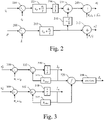
- Fig. 2 represents an example of a block diagram of a direct flux vector control module.
- the direct flux vector control module 110 comprises a subtracting module 220 that subtracts from the reference current i ⁇ * in the ⁇ axis, the measured current i ⁇ in the ⁇ axis.
- the output of the subtracting module 220 is provided to a PI regulator 225 the output of which is provided to a multiplication module 230 that multiplies the output of the PI regulator 225 by a decoupling constant value 1/b.
- the output of the subtracting module 200 is provided to a PI regulator 205 the output of which is provided to a multiplication module 210 that multiplies the output of the PI regulator 255 by a decoupling constant value -a/b that is dependent of the motor.
- the outputs of the multiplication modules 230 and 210 are summed by a summation module 235.
- the output of the summation module 235 is provided to a summation module 240 that sums the result of the summation performed by the summation module 235 to R s i ⁇ + ⁇ in order to provide the reference voltage v * ⁇ in the ⁇ axis, where Rs is the stator resistance, and ⁇ is the estimated motor speed.
- the Stator resistance Rs is for example obtained from a self-commissioning procedure.
- the motor speed is estimated from the variations of the angle ⁇ s of the estimated flux vector.
- the output of the PI regulator 205 is provided to a summation module 215 that sums the result of the output of the PI regulator 205 to R s i f in order to provide the reference voltage v * f in the f axis.
- Fig. 3 represents an example of a block diagram of a flux observer module.
- the flux estimation module 150 comprises a subtracting module 300 that subtracts from the reference voltage v * ⁇ in the ⁇ axis the current i ⁇ in the ⁇ axis multiplied by the resistance Rs.
- the result of the subtracting module 300 is provided to a subtracting module 305.
- the subtracting module 305 subtracts from the result of the subtracting module 300 a result provided by a multiplication module 315.
- the output of the subtracting module 305 is provided to an integrator 310 in order to provide the estimated flux ⁇ ⁇ in the ⁇ axis.
- the estimated flux ⁇ ⁇ in the ⁇ axis is provided to a divider 320 and to the multiplication module 315 that multiplies the estimated flux ⁇ ⁇ in the ⁇ axis by a coefficient k obs that is an observation gain.
- the flux estimation module 150 comprises a subtracting module 330 that subtracts from the reference voltage v * ⁇ in the ⁇ axis the current i ⁇ in the ⁇ axis multiplied by the resistance Rs of the motor 135.
- the result of the subtracting module 330 is provided to a subtracting module 335.
- the subtracting module 335 subtracts from the result of the subtracting module 330 a result provided by a multiplication module 345.
- the output of the subtracting module 335 is provided to an integrator 340 in order to provide the estimated flux ⁇ ⁇ in the ⁇ axis.
- the estimated flux ⁇ ⁇ in the ⁇ axis is provided to the divider 320 and to the multiplication module 345 that multiplies the estimated flux ⁇ ⁇ in the ⁇ axis by the coefficient k obs .
- the division module 320 divides the estimated flux ⁇ ⁇ in the ⁇ axis by the estimated flux ⁇ ⁇ in the ⁇ axis.
- the result of the division module 320 is transformed by arctangent by the module 350 in order to provide the estimated load angle ⁇ s .
- Fig. 4 represents an example of a block diagram of a maximum torque per ampere module.
- the maximum torque per ampere module 155 comprises a framework transformation module 400 that transforms the estimated flux ⁇ ⁇ in the ⁇ framework into an estimated flux ⁇ ij in the ij framework using a measured angle ⁇ s between the measured currents and the ⁇ axis of ⁇ framework.
- the estimated flux ⁇ j in the j axis is provided to multiplier 415 that multiplies the estimated flux ⁇ j in the j axis by the high frequency sinewave signal sin ( ⁇ h t ).
- the output of the multiplication module 415 is processed by a low pass filter 420.
- Modules 415 and 420 form a heterodyne demodulation 410.
- the output of the heterodyne modulation 410 is provided to a PI regulator 425 with an integral gain of k ⁇ and proportional gain zero in order to provide the reference flux ⁇ MTPA * .
- the reference flux ⁇ MTPA * is thus controlled to ensure that the flux response to the high frequency injection voltage is null on the j axis, and thus only located on the i axis.
- the high frequency flux response to the injected voltage is aligned with the measured current vector.
- Fig. 5a represents a first example of a block diagram of an injection module according to the present invention.
- the xy framework is rotated from the ⁇ framework by an angle equal to sum of the measured angle and a fixed angle ⁇ minus ⁇ /2. ⁇ is comprised between 0 and ⁇ /2. Only the measured current in the x axis is provided to a multiplier 505. In other words, the measured current motor vector is projected in the x axis.
- the measured current in the x axis corresponds to the projection of the measured current vector in the direction orthogonal to the fixed angle ⁇ .
- the multiplier 505 multiplies the high frequency sinewave sin ( ⁇ h t ) to the measured current in the x axis in order to demodulate the high frequency variations of the norm of the measured current motor vector.
- the output of the multiplier 505 is provided to a low pass filter 510.
- the output of the low pass filter 510 is provided to a Proportional Integral regulator 515 with an integral gain of k 1 which value is between 0.01 and 0.5 depending on the machine ratings, the injection frequency and magnitude and the sampling frequency, and a proportional gain equal to null value.
- the output of the proportional integral regulator 515 is an angle ⁇ that is provided to a transformation module 520.
- the transformation module 520 performs an e J ⁇ + ⁇ s transform where J is the matrix 0 ⁇ 1 + 1 0 .
- the output of the transformation module 520 is provided to a multiplier 525.
- the multiplier 525 multiplies the output of the transformation module 520 by the high frequency signal v h cos( ⁇ h t ) where v h is the amplitude of the voltage injection in order to obtain the voltage injection signal v ⁇ inj in the ⁇ framework.
- Fig. 5b represents a second example of a block diagram of an injection module according to the present invention.
- the xy framework is rotated from the ⁇ framework by an angle equal to sum of the measured angle and the fixed angle ⁇ minus ⁇ /2.
- ⁇ is comprised between 0 and ⁇ /2.
- the measured current in the x axis is provided to a multiplier 552.
- the measured current in the x axis corresponds to the projection of measured current vector in the direction orthogonal to the fixed angle ⁇ .
- the multiplier 552 multiplies the quadrature high frequency sine waveform sin ( ⁇ h t ) to the measured current in the x axis in order to demodulate the high frequency variations of the measured current in the x axis.
- the output of the multiplier 552 is provided to a low pass filter 554.
- the low pass filter 554 has a cut frequency which is smaller than the frequency ⁇ h of the injected signal.
- the output of the low pass filter 554 is provided to a Proportional Integral regulator 556 with an integral gain of k 1 , which value is between 0.01 and 0.5 depending on the machine ratings, the injection frequency and magnitude and the sampling frequency, and a proportional gain equal to null value.
- the output of the proportional integral regulator 556 is a first angle that is provided to a multiplier 558.
- the measured current in the x axis is provided to a multiplier 562.
- the multiplier 562 multiplies the in-phase high frequency cosine waveform cos ( ⁇ h t ) to the measured current in the x axis in order to demodulate the high frequency variations of the measured current in the x axis.
- the output of the multiplier 562 is provided to a low pass filter 564.
- the low pass filter 564 has a cut frequency which is smaller than the frequency ⁇ h of the injected signal ⁇ h .
- the output of the low pass filter 564 is provided to a Proportional Integral regulator 568 with an integral gain of k 1 , the value of which is between 0.01 to 0.5 and a proportional gain equal to null value.
- the output of the proportional integral regulator 568 is provided to a multiplier 570 and is a second angle.
- the demodulated and filtered measured current in the x axis ⁇ Q and ⁇ I is provided to a weight calculation module 560 that determines a weight ⁇ Q that is provided to the multiplier 558 and a weight ⁇ Q that is provided to the multiplier 558.
- the output ⁇ Q of the weight calculation module 560 is multiplied to the first angle provided by the proportional integral regulator 556 by a multiplier 558.
- the output ⁇ I of the weight calculation module 560 is multiplied to the second angle provided by the proportional integral regulator 568 by a multiplier 570.
- the outputs of the multipliers 558 and 570 are summed by a summation module 572.
- the output of the summation module 572 is an angle ⁇ that is provided to a transformation module 576.
- the transformation module 576 performs an e J ⁇ + ⁇ s transform where J is the matrix 0 ⁇ 1 + 1 0 .
- the output of the transformation module 576 is provided to a multiplier 578.
- the multiplier 578 multiplies the output of the transformation module 574 by the high frequency signal v h cos( ⁇ h t ) where v h is the voltage injection amplitude in order to obtain the injection signal voltage v ⁇ inj in the ⁇ framework.
- Fig. 6 represents a third example of a block diagram of an injection module according to the present invention.
- the injection module 125 has, for example, an architecture based on components connected by a bus 601 and a processor 600 controlled by a program as disclosed in Fig. 8a or 8b .
- the bus 601 links the processor 600 to a read only memory ROM 602, a random access memory RAM 603, an input output I/O IF interface 605.
- the input output I/O IF interface 605 enables the injection module 125 to sense signals representative of current flowing through the motor 135 and predetermined signals.
- the memory 603 contains registers intended to receive variables and the instructions of the program related to the algorithm as disclosed in Fig. 8a or 8b .
- the read-only memory or possibly a Flash memory 602, contains instructions of the programs related to the algorithm as disclosed in Fig. 8a or 8b , when the injection module 125 is powered on, that are loaded to the random access memory 603.
- the program may also be executed directly from the ROM memory 602.
- the calculation performed by the injection module 125 may be implemented in software by execution of a set of instructions or program by a programmable computing machine, such as a PC (Personal Computer), a DSP ( Digital Signal Pr o cessor) or a microcontroller; or else implemented in hardware by a machine or a dedicated component, such as an FPGA (Field-Programmable Gate Array ) or an ASIC (Application-Specific Integrated Circuit).
- a programmable computing machine such as a PC (Personal Computer), a DSP ( Digital Signal Pr o cessor) or a microcontroller; or else implemented in hardware by a machine or a dedicated component, such as an FPGA (Field-Programmable Gate Array ) or an ASIC (Application-Specific Integrated Circuit).
- the injection module 125 includes circuitry, or a device including circuitry, causing the injection module 125 to perform the program related to the algorithm as disclosed in Fig. 8a or 8b .
- Fig. 7 represents the motor frameworks used by the present invention.
- ⁇ two phase stator framework is represented.
- the ⁇ framework is static in reference to the stator of the motor.
- the dq two phase rotor framework is represented.
- the dq framework is dynamic and follows the rotor position ⁇ .
- the ij two phase current framework is represented.
- the i axis follows the current vector, forming an angle ⁇ s with the ⁇ axis, while the j axis is perpendicular to the current vector.
- the ft two phase flux framework is represented.
- the f axis follows the estimated flux vector, forming an angle ⁇ s with the ⁇ axis, while the ⁇ axis is perpendicular to the estimated flux vector.
- the xy framework is represented.
- the y axis follows the fixed angle ⁇ with the vector current in the x axis.
- the HF current response i HF to the high frequency voltage injection is represented.
- the HF current response i HF is perpendicular to the x axis, thus forming the fixed angle ⁇ with the measured current vector flowing in the machine.
- the HF response ⁇ HF of the estimated flux to the high frequency injection voltage is represented.
- the HF response ⁇ HF is aligned with the i axis, thus aligned with the measured current vector.
- Fig. 8a represents a first example of an algorithm for determining an injection voltage vector to be added to a signal for driving a motor according to the invention.
- the present algorithm is disclosed in an example wherein it is executed by the processor 600 of the injection module 125.
- the processor 600 obtains measurements of the motor current vector.
- the processor 600 demodulates the high frequency variations of the measured current in the x axis using a first high frequency demodulation signal sin ( ⁇ h t ).
- the processor 600 executes a first low pass filtering of the demodulated high frequency variations of the measured current in the x axis using the first high frequency signal.
- the processor 600 determines at least a first angle ⁇ from the first low pass filtered demodulated measured current in the x axis by the first high frequency signal, for example using a Proportional Integral regulator with an integral gain of k 1 and a proportional gain equal to null value.
- the processor 600 determines the injection voltage vector at least from the first angle, a predetermined voltage and a first high frequency modulating signal, the first high frequency modulating signal having the same frequency as the first high frequency demodulating signal and a phase difference with the first high frequency demodulating signal that is equal to ⁇ /2.
- the processor 600 determines the injection voltage vector by executing an e J ⁇ + ⁇ s transform where J is the matrix 0 ⁇ 1 + 1 0 that is multiplied by the high frequency signal v h cos( ⁇ h t ) where v h is the amplitude of the voltage injection in order to obtain the injection voltage vector v ⁇ inj in the ⁇ framework.
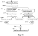
- Fig. 8b represents a second example of an algorithm for determining an injection voltage vector to be added to a signal for driving a motor according to the invention.
- the present algorithm is disclosed in an example wherein it is executed by the processor 600 of the injection module 125.
- the processor 600 obtains measurements of the motor current vector.
- the processor 600 demodulates the high frequency variations of the measured current in the x axis using a first high frequency demodulation signal sin ( ⁇ h t ) .
- the processor 600 executes a first low pass filtering of the demodulated high frequency variations of the measured current in the x axis using the first high frequency demodulation signal.
- the processor 600 determines a first angle from the first low pass filtered demodulated high frequency variations of the measured current in the x axis by the first high frequency demodulation signal, for example using a Proportional Integral regulator with an integral gain of k 1 and a proportional gain equal to null value.
- the processor 600 demodulates the high frequency variations of the measured current in the x axis using a second high frequency demodulation signal cos ( ⁇ h t ).
- the processor 600 executes a second low pass filtering of the demodulated high frequency variations of the measured current in the x axis using the second high frequency demodulation signal.
- the processor 600 determines a second angle from the second low pass filtered demodulated high frequency variations of the measured current in the x axis by the second high frequency demodulation signal, for example using a Proportional Integral regulator with an integral gain of k 1 and a proportional gain equal to null value.
- step S858 the processor 600 using the demodulated and filtered measured currents in the x axis ⁇ I and ⁇ IQ provided respectively by the low pass filtering steps S853 and S856 determines weights ⁇ I and ⁇ Q .
- the processor 600 multiplies the first angle by the weight ⁇ Q .
- step S860 the processor 600 multiplies the second angle by the weight ⁇ I .
- step S861 the processor 600 sums the outputs of the steps S859 and S860.
- the output of the summation step is an injection angle ⁇ that is transformed at step S862 by the processor 600 using an e J ⁇ + ⁇ s transform where J is the matrix 0 ⁇ 1 + 1 0 . and modulated by the second high frequency signal v h cos ( ⁇ h t ) where v h is the voltage injection amplitude in order to obtain the injection signal voltage v ⁇ inj in the ⁇ framework.
Landscapes
- Engineering & Computer Science (AREA)
- Power Engineering (AREA)
- Control Of Ac Motors In General (AREA)
Abstract
- measures the motor current vector,
- determines a projection value of the motor current on an axis that is orthogonal to a direction having the fixed angle with the measured current vector,
- demodulates the high frequency variations of the projection valueusing a first high frequency demodulation signal,
- determines at least a first angle from the demodulated high frequency variation,
- determines the injection voltage vector at least from the first angle, a predetermined voltage and a second high frequency modulating signal, the second high frequency modulating signal having the same frequency as the first high frequency demodulating signal and a phase difference with the first high frequency demodulating signal that is equal to Π/2.
Description
- The present invention relates generally to a method and a device for injecting a high frequency current vector which has a fixed angle with the measured current vector flowing in the machine.
- Electrical machines are widely used on the industry either for factory automation or transportation. Many control techniques for machines as Permanent Magnet Synchronous Machines (PMSM), Synchronous Reluctance Machines (SyncRM), Wounded Rotor Synchronous Machines (WRSM) often use a rotary encoder for obtaining the speed and the position of the machine as feedback.
- The demands for low-cost and robust motor drives have increased the development of sensorless control. Without those sensors the machine drives become less expensive and more robust to dusty and harsh environments.
- Many controller technologies rely on high frequency signal injection. The injected HF voltage signal is generally superposed to the control voltage waveforms of the machine, causing HF variations of flux in the machine, finally causing HF variations of currents flowing through the machine conductors.
- The relation between HF variations of the flux and of the current contains precious information on machine inductances. As example, in absence of position sensor, these information can be used to determine the position of the rotor of the machine. As another example, relationship between chord and incremental inductances can drive the choice of current shoot angle, so as to reach MTPA (Maximum Torque Per ampere) operation point. MTPA conditions produce torque with minimal level of current, thus of losses.
- Ideal MTPA operation point is typically identified using lookup tables (LUT). MTPA LUT may be determined manually, or may be built on other inductance or flux maps, which determination also requires specific self commissionning sessions. LUT-less MTPA consists in identifying MTPA operation point in absence of lookup table.
- Different injection techniques are known such as sinusoidal, square, and several techniques can be combined across different frequencies and axis frameworks, possibly addressing different purposes, e.g. leading to circular or elliptic injection.
- Injection in dq framework, which rotates together with the rotor of the machine and heads to most/least salient directions of the rotor, is popular as it can get used to quickly identify incremental inductances in extreme saliency regions. In contrast, injection in alpha-beta framework, that is fixed and related to stator, requires no knowledge on rotor position.
- HF signal injection can be implemented as voltage or current form. While HF voltage injection is straightforward, current injection requires a current regulator, that produces a voltage pattern to drive the measured current towards the desired HF current injection waveform.
- The current regulator must be designed with high bandwidth, to enable the tracking of the distance to the desired HF injection signal. This high bandwidth causes a high level of noise on the estimation of instantaneous direction of injection.
- If the injected signal is then used for the estimation of rotor position, or for the estimation of ideal shoot angle of motor current to realise MTPA conditions, both noisy estimations can cause instability of the sensorless controller of the machine. This generally requires to limit the bandwith of speed controller to avoid divergence and limits the applicability of sensorless control to low bandwidth applications.
- As the regulator bandwidth is necessarily limited by the switching frequency of the inverter, it is also impossible to inject a very high frequency current, e.g. oscillating close to the switching frequency.
- In contrast, some LUT-less MTPA technologies rely on HF current injection strictly perpendicular to the measured current. However, aforementionned problems limit the use of HF current injection for LUT-less MTPA in practical applications in both litterature and industry.
- To improve the stability and bandwitdh of the sensorless control of the machine in absence of LUT, the invention proposes a method for injecting a high frequency current vector which has a fixed angle with the measured current vector flowing in the machine.
- The present invention aims to provide a method for injecting a high frequency current vector which has a fixed angle with the measured current vector flowing in the machine.
- To that end, the present invention concerns a method for injecting a high frequency current vector which has a fixed angle with the measured current vector flowing in the machine, characterized in that the method comprises the steps of:
- measuring the motor current vector,
- determining a projection value of the motor current vector on an axis that is orthogonal to a direction having the fixed angle with the measured current vector,
- demodulating the high frequency variations of the projection value using a first high frequency demodulation signal,
- determining at least a first angle from the demodulated high frequency variations,
- determining the injection voltage vector at least from the first angle, a predetermined voltage and a second high frequency modulating signal, the second high frequency modulating signal having the same frequency as the first high frequency demodulating signal and a phase difference with the first high frequency demodulating signal that is equal to Π/2.
- The present invention concerns also a device for injecting a high frequency current vector which has a fixed angle with the measured current vector flowing in the machine, characterized in that the device comprises:
- means for measuring the motor current vector,
- means for determining a projection value of the motor current on an axis that is orthogonal to a direction having the fixed angle with the measured current vector,
- means for demodulating the high frequency variations of the projection value using a first high frequency demodulation signal,
- means for determining at least a first angle from the demodulated high frequency variation,
- means for determining the injection voltage vector at least from the first angle, a predetermined voltage and a second high frequency modulating signal, the second high frequency modulating signal having the same frequency as the first high frequency demodulating signal and a phase difference with the first high frequency demodulating signal that is equal to Π/2.
- Thus, the first angle is driven to minimise the projection of HF current orthogonal to the desired direction. As the machine is mainly inductive, the resulting HF current necessarily flows in the desired direction, forming the fixed angle with the measured current vector flowing in the machine. The perturbations on controller stability, resulting from non constant angle, are much reduced, globally increasing the stability of the controller.
- According to a particular feature, the injection voltage vector is determined from the first angle ψ and the angle of measured current vector γs by executing an e Jψ+γs transform where J is the matrix

- Thus, the voltage vector forms a stable angle ψ with the measured current vector. This angle is controlled to drive the HF response of the current in the desired direction having a fixed angle with the measured current vector. The angle ψ does not need to follow the rotation of the measured current vector with the fundamental frequency, relaxing the constraints on the design of a PI filter. The direction of high frequency current injection is well stabilised with respect to measured current vector. The injection frequency can get increased, up to the switching frequency of the inverter. The ability of the controller to react to fast injection is increased, e.g. it can estimate more quickly the MTPA and the voltage levels needed to reach a desired torque. The controller performance is globally improved despite of absence of lookup tables of machine parameters.
- According to a particular feature, the method further comprises the steps of:
- demodulating the high frequency variations of the projection value using a second high frequency demodulation signal having the same frequency as the first high frequency demodulating signal and a phase difference with the first high frequency demodulating signal that is equal to Π/2,
- determining a second angle from the high frequency variations of the projection value demodulated using the second high frequency demodulating signal,
- weighting the first and second angles by respective weights that are determined from the demodulated high frequency variations of the values of the motor current on the axis that is orthogonal to the direction having the fixed angle with the measured current vector using the first and second high frequency demodulating signals,
- summing the weighted first and second angles,
- Thus, both the quadrature and in phase components of the HF current response are minimised orthogonally to the desired injection direction. The HF current response can hold the two components due to the complex response of the machine, that contains both in phase (resistive) and quadrature impedances (inductive). The method needs no assumption on the impedance of the machine and equally operates at any injection frequency. The signal to noise ratio on the desired angle is improved.
- According to a particular feature, the projection value of the motor current on the axis that is orthogonal to the direction having the fixed angle with the measured current vector is determined by transforming the measured current motor vector iαβ in the αβ framework into a measured current motor vector ixy in the xy framework using a measured angle γs between the measured current vector in the αβ framework and the α axis of αβ framework where

- Thus, the angle of the current vector in the machine is precisely calculated.
- According to a particular feature, the determining of the first angle from the demodulated high frequency variation is performed using a Proportional Integral regulator with an integral gain of k1 and a proportional gain equal to null value.
- Thus, the present invention enables to obtain an angle that ensures that the high frequency inductive component of the motor current vector has a fixed angle with respect to the measured current vector flowing in a machine.
- According to a particular feature, the determining of the second angle is performed using a Proportional Integral regulator with the integral gain of k1 and a proportional gain equal to null value.
- Thus, the present invention enables to obtain an angle that ensures that the high frequency inductive component of the motor current vector has a fixed angle with respect to the measured current vector flowing in a machine.
- The characteristics of the invention will emerge more clearly from a reading of the following description of example embodiments, the said description being produced with reference to the accompanying drawings, among which:
-
Fig. 1 represents an example of a direct flux vector control of a motor using maximum torque per ampere in which the present invention is implemented; -
Fig. 2 represents an example of a block diagram of a direct flux vector control module; -
Fig. 3 represents an example of a block diagram of a flux observer module; -
Fig. 4 represents an example of a block diagram of a maximum torque per ampere module; -
Fig. 5a represents a first example of a block diagram of an injection module according to the present invention; -
Fig. 5b represents a second example of a block diagram of an injection module according to the present invention; -
Fig. 6 represents a third example of a block diagram of an injection module according to the present invention; -
Fig. 7 represents the motor frameworks used by the present invention; -
Fig. 8a represents a first example of an algorithm for determining an injection voltage vector to be added to a signal for driving a motor according to the invention; -
Fig. 8b represents a second example of an algorithm for determining an injection voltage vector to be added to a signal for driving a motor according to the invention. -
Fig. 1 represents a first example of a direct flux vector control of a motor using maximum torque per ampere in which the present invention is implemented. - It has to be noted here that the present invention is disclosed in an example wherein an MTPA module is used. The present invention is also applicable for example for determining the position of the machine or estimating parameters of the machine under control.
- In the system shown in
Fig. 1 , the reference torque T* is fed to adivider 100 together with a reference flux
MTPA tracking module 155 and 3/2 times the number of poles pairs of themotor 135 in order to obtain a reference current
DFVC module 110.
- The
DFVC module 110, from the reference current

MTPA tracking module 155, determine a reference voltage v* fτ in the ft framework. - The reference voltage v*fτ in the ft framework is provided to a
framework transformation module 115 that transforms the reference voltage v*fτ in the fτ framework into a reference voltage v* αβ in the αβ framework using an estimated load angle δ̂s . - The reference voltage v*αβ in the αβ framework is provided to a
summation module 120 that sums the reference voltage v* αβ with high frequency injection voltage vαβinj in the αβ framework in order to obtain a modified reference voltage v**αβ in the αβ framework. - The modified reference voltage v** αβ in the αβ framework is provided to a voltage
source inverter VSI 130 that is connected to themotor 135. The motor current vector iabc measured in the three phases abc is provided to aframework transformation module 140. - The
framework transformation module 140 transforms the motor current iabc measured in the three phases abc in a measured motor current vector iαβ in the αβ framework. - The measured current motor vector iαβ in the αβ framework is provided to a
flux estimation module 150, a j-axis injection module 125 and to aframework transformation module 145. - The
framework transformation module 145 transforms the measured current motor vector iαβ in the αβ framework into a measured current motor vector ifτ the ft framework using an estimated load angle δ̂s . - The measured current vector ifτ in the ft axis is provided to the
DFVC module 110. - The
injection module 125 determines the injection voltage vector vαβinj in the αβ framework from the measured current motor vector iαβ in the αβ framework and a high frequency signals sin(ωht) and cos(ωht). - The high frequency injection voltage (vαβinj ) is determined in order to provide a high frequency current response of the motor to the injected voltages that are perpendicular to the measured motor current vector.
- The high frequency injection voltage (vαβinj ) is in a frequency range between 100Hz-to the switching frequency of the voltage
source inverter VSI 130. - The
flux estimation module 150 determines, from the measured current motor vector iαβ in the αβ framework and the voltage references v*αβ , the estimated flux λ̂αβ in the αβ framework and the estimated load angle δ̂s . - The
speed estimation module 152 determines the speed of themotor 135 from the estimated load angle. - For example, the speed ω̂ is estimated using a phase lock loop and a low pass filtering of the output of the phase lock loop.
- The estimated flux λ̂αβ in the αβ framework is provided to a
MTPA tracking module 155 and to theDFVC module 110. - The
MTPA tracking module 155 determines, from the estimated flux λ̂αβ in the αβ framework and the high frequency sinewave signal sin(ωht), the reference flux
-
Fig. 2 represents an example of a block diagram of a direct flux vector control module. - The direct flux
vector control module 110 comprises asubtracting module 220 that subtracts from the reference current
- The output of the
subtracting module 220 is provided to aPI regulator 225 the output of which is provided to amultiplication module 230 that multiplies the output of thePI regulator 225 by a decouplingconstant value 1/b. - The direct flux
vector control module 110 comprises asubtracting module 200 that subtracts from the reference flux

subtracting module 200 is provided to aPI regulator 205 the output of which is provided to amultiplication module 210 that multiplies the output of the PI regulator 255 by a decoupling constant value -a/b that is dependent of the motor. As example, values for a and b are a=4 and b=13. - The outputs of the
multiplication modules summation module 235. - The output of the
summation module 235 is provided to asummation module 240 that sums the result of the summation performed by thesummation module 235 to Rsiτ + λ̂ω̂ in order to provide the reference voltage v* τ in the τ axis, where Rs is the stator resistance, and ω̂ is the estimated motor speed. - The Stator resistance Rs is for example obtained from a self-commissioning procedure. The motor speed is estimated from the variations of the angle δ̂s of the estimated flux vector.
- The output of the
PI regulator 205 is provided to asummation module 215 that sums the result of the output of thePI regulator 205 to Rsif in order to provide the reference voltage v* f in the f axis. -
Fig. 3 represents an example of a block diagram of a flux observer module. - The
flux estimation module 150 comprises asubtracting module 300 that subtracts from the reference voltage v* α in the α axis the current iα in the α axis multiplied by the resistance Rs. - The result of the
subtracting module 300 is provided to asubtracting module 305. - The
subtracting module 305 subtracts from the result of the subtracting module 300 a result provided by amultiplication module 315. - The output of the
subtracting module 305 is provided to anintegrator 310 in order to provide the estimated flux λ̂α in the α axis. - The estimated flux λ̂α in the α axis is provided to a
divider 320 and to themultiplication module 315 that multiplies the estimated flux λ̂α in the α axis by a coefficient kobs that is an observation gain. - The
flux estimation module 150 comprises asubtracting module 330 that subtracts from the reference voltage v* β in the β axis the current iβ in the β axis multiplied by the resistance Rs of themotor 135. - The result of the
subtracting module 330 is provided to asubtracting module 335. - The
subtracting module 335 subtracts from the result of the subtracting module 330 a result provided by amultiplication module 345. - The output of the
subtracting module 335 is provided to anintegrator 340 in order to provide the estimated flux λ̂β in the β axis. - The estimated flux λ̂β in the β axis is provided to the
divider 320 and to themultiplication module 345 that multiplies the estimated flux λ̂β in the β axis by the coefficient kobs. - The
division module 320 divides the estimated flux λ̂β in the β axis by the estimated flux λ̂α in the α axis. - The result of the
division module 320 is transformed by arctangent by themodule 350 in order to provide the estimated load angle δ̂s . -
Fig. 4 represents an example of a block diagram of a maximum torque per ampere module. - The maximum torque per
ampere module 155 comprises aframework transformation module 400 that transforms the estimated flux λ̂β in the αβ framework into an estimated flux λ̂ij in the ij framework using a measured angle γs between the measured currents and the α axis of αβ framework. - The estimated flux λ̂j in the j axis is provided to
multiplier 415 that multiplies the estimated flux λ̂j in the j axis by the high frequency sinewave signal sin(ωht). - The output of the
multiplication module 415 is processed by alow pass filter 420. -
Modules heterodyne demodulation 410. - The output of the
heterodyne modulation 410 is provided to aPI regulator 425 with an integral gain of kλ and proportional gain zero in order to provide the reference flux
- The reference flux

-
Fig. 5a represents a first example of a block diagram of an injection module according to the present invention. - The
injection module 125 comprises aframework transformation module 500 that transforms the measured current motor vector iαβ in the αβ framework into a measured current motor vector ixy in the xy framework using a measured angle γs between the measured current vector in the αβ framework where
multiplier 505. In other words, the measured current motor vector is projected in the x axis. The measured current in the x axis corresponds to the projection of the measured current vector in the direction orthogonal to the fixed angle Δ. Themultiplier 505 multiplies the high frequency sinewave sin(ωht) to the measured current in the x axis in order to demodulate the high frequency variations of the norm of the measured current motor vector. - The output of the
multiplier 505 is provided to alow pass filter 510. - The output of the
low pass filter 510 is provided to aProportional Integral regulator 515 with an integral gain of k1 which value is between 0.01 and 0.5 depending on the machine ratings, the injection frequency and magnitude and the sampling frequency, and a proportional gain equal to null value. The output of the proportionalintegral regulator 515 is an angle ψ that is provided to atransformation module 520. - The
transformation module 520 performs an e Jψ+γstransform where J is the matrix
- The output of the
transformation module 520 is provided to amultiplier 525. Themultiplier 525 multiplies the output of thetransformation module 520 by the high frequency signal vh cos(ωht) where vh is the amplitude of the voltage injection in order to obtain the voltage injection signal vαβinj in the αβ framework. -
Fig. 5b represents a second example of a block diagram of an injection module according to the present invention. - The
injection module 125 comprises aframework transformation module 550 that transforms the measured current motor vector iαβ in the αβ framework into a measured current motor vector ixy in the xy framework using a measured angle γs between the measured current vector in the αβ framework and the α axis of αβ framework where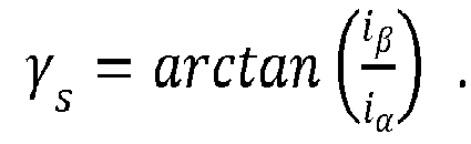
- The measured current in the x axis is provided to a
multiplier 552. The measured current in the x axis corresponds to the projection of measured current vector in the direction orthogonal to the fixed angle Δ. Themultiplier 552 multiplies the quadrature high frequency sine waveform sin(ωht) to the measured current in the x axis in order to demodulate the high frequency variations of the measured current in the x axis. The output of themultiplier 552 is provided to alow pass filter 554. - The
low pass filter 554 has a cut frequency which is smaller than the frequency ωh of the injected signal. - The output of the
low pass filter 554 is provided to a Proportional Integral regulator 556 with an integral gain of k1 , which value is between 0.01 and 0.5 depending on the machine ratings, the injection frequency and magnitude and the sampling frequency, and a proportional gain equal to null value. The output of the proportional integral regulator 556 is a first angle that is provided to amultiplier 558. - The measured current in the x axis, or in other words projected in the x axis, is provided to a
multiplier 562. Themultiplier 562 multiplies the in-phase high frequency cosine waveform cos(ωht) to the measured current in the x axis in order to demodulate the high frequency variations of the measured current in the x axis. The output of themultiplier 562 is provided to alow pass filter 564. - The
low pass filter 564 has a cut frequency which is smaller than the frequency ωh of the injected signal ωh. - The output of the
low pass filter 564 is provided to aProportional Integral regulator 568 with an integral gain of k1 , the value of which is between 0.01 to 0.5 and a proportional gain equal to null value. The output of the proportionalintegral regulator 568 is provided to amultiplier 570 and is a second angle. - The demodulated and filtered measured current in the x axis βQ and βI is provided to a weight calculation module 560 that determines a weight αQ that is provided to the
multiplier 558 and a weight αQ that is provided to themultiplier 558.
- The output αQ of the weight calculation module 560 is multiplied to the first angle provided by the proportional integral regulator 556 by a
multiplier 558. - The output αI of the weight calculation module 560 is multiplied to the second angle provided by the proportional
integral regulator 568 by amultiplier 570. - The outputs of the
multipliers summation module 572. - The output of the
summation module 572 is an angle ψ that is provided to atransformation module 576. Thetransformation module 576 performs an e Jψ+γs transform where J is the matrix
- The output of the
transformation module 576 is provided to amultiplier 578. Themultiplier 578 multiplies the output of the transformation module 574 by the high frequency signal vh cos(ωht) where vh is the voltage injection amplitude in order to obtain the injection signal voltage vαβinj in the αβ framework. -
Fig. 6 represents a third example of a block diagram of an injection module according to the present invention. - The
injection module 125 has, for example, an architecture based on components connected by abus 601 and aprocessor 600 controlled by a program as disclosed inFig. 8a or8b . - The
bus 601 links theprocessor 600 to a read onlymemory ROM 602, a randomaccess memory RAM 603, an input output I/O IF interface 605. - The input output I/
O IF interface 605 enables theinjection module 125 to sense signals representative of current flowing through themotor 135 and predetermined signals. - The
memory 603 contains registers intended to receive variables and the instructions of the program related to the algorithm as disclosed inFig. 8a or8b . - The read-only memory, or possibly a
Flash memory 602, contains instructions of the programs related to the algorithm as disclosed inFig. 8a or8b , when theinjection module 125 is powered on, that are loaded to therandom access memory 603. Alternatively, the program may also be executed directly from theROM memory 602. - The calculation performed by the
injection module 125 may be implemented in software by execution of a set of instructions or program by a programmable computing machine, such as a PC (Personal Computer), a DSP (Digital Signal Processor) or a microcontroller; or else implemented in hardware by a machine or a dedicated component, such as an FPGA (Field-Programmable Gate Array) or an ASIC (Application-Specific Integrated Circuit). - In other words, the
injection module 125 includes circuitry, or a device including circuitry, causing theinjection module 125 to perform the program related to the algorithm as disclosed inFig. 8a or8b . -
Fig. 7 represents the motor frameworks used by the present invention. - In
Fig. 7 , αβ two phase stator framework is represented. The αβ framework is static in reference to the stator of the motor. - The dq two phase rotor framework is represented. The dq framework is dynamic and follows the rotor position θ.
- The ij two phase current framework is represented. The i axis follows the current vector, forming an angle γs with the α axis, while the j axis is perpendicular to the current vector.
- The ft two phase flux framework is represented. The f axis follows the estimated flux vector, forming an angle γs with the α axis, while the τ axis is perpendicular to the estimated flux vector.
- The xy framework is represented. The y axis follows the fixed angle Δ with the vector current in the x axis.
- The HF current response iHF to the high frequency voltage injection is represented. The HF current response iHF is perpendicular to the x axis, thus forming the fixed angle Δ with the measured current vector flowing in the machine.
- The HF response λHF of the estimated flux to the high frequency injection voltage is represented. The HF response λHF is aligned with the i axis, thus aligned with the measured current vector.
-
Fig. 8a represents a first example of an algorithm for determining an injection voltage vector to be added to a signal for driving a motor according to the invention. - The present algorithm is disclosed in an example wherein it is executed by the
processor 600 of theinjection module 125. - At step S800, the
processor 600 obtains measurements of the motor current vector. - At step S801, the
processor 600 determines the projection of the motor current vector in the direction orthogonal to the fixed angle Δ for example by transforming the measured current motor vector iαβ in the αβ framework into a measured current motor vector ixy in the xy framework using a measured angle γs between the measured currents in the αβ framework where
- At step S802, the
processor 600 demodulates the high frequency variations of the measured current in the x axis using a first high frequency demodulation signal sin(ωht). - At step S803, the
processor 600 executes a first low pass filtering of the demodulated high frequency variations of the measured current in the x axis using the first high frequency signal. - At step S804, the
processor 600 determines at least a first angle ψ from the first low pass filtered demodulated measured current in the x axis by the first high frequency signal, for example using a Proportional Integral regulator with an integral gain of k1 and a proportional gain equal to null value. - At step S805, the
processor 600 determines the injection voltage vector at least from the first angle, a predetermined voltage and a first high frequency modulating signal, the first high frequency modulating signal having the same frequency as the first high frequency demodulating signal and a phase difference with the first high frequency demodulating signal that is equal to Π/2. - For example, the
processor 600 determines the injection voltage vector by executing an e Jψ+γs transform where J is the matrix
-
Fig. 8b represents a second example of an algorithm for determining an injection voltage vector to be added to a signal for driving a motor according to the invention. - The present algorithm is disclosed in an example wherein it is executed by the
processor 600 of theinjection module 125. - At step S850, the
processor 600 obtains measurements of the motor current vector. - At step S851, the
processor 600 determines the projection of the motor current vector in the direction orthogonal to the fixed angle Δ for example by transforming the measured current motor vector iαβ in the αβ framework into a measured current motor vector ixy in the xy framework using a measured angle γs between the measured currents in the αβ framework where
- At step S852, the
processor 600 demodulates the high frequency variations of the measured current in the x axis using a first high frequency demodulation signal sin(ωht). - At step S853, the
processor 600 executes a first low pass filtering of the demodulated high frequency variations of the measured current in the x axis using the first high frequency demodulation signal. - At step S854, the
processor 600 determines a first angle from the first low pass filtered demodulated high frequency variations of the measured current in the x axis by the first high frequency demodulation signal, for example using a Proportional Integral regulator with an integral gain of k1 and a proportional gain equal to null value. - At step S855, the
processor 600 demodulates the high frequency variations of the measured current in the x axis using a second high frequency demodulation signal cos(ωht). - At step S856, the
processor 600 executes a second low pass filtering of the demodulated high frequency variations of the measured current in the x axis using the second high frequency demodulation signal. - At step S857, the
processor 600 determines a second angle from the second low pass filtered demodulated high frequency variations of the measured current in the x axis by the second high frequency demodulation signal, for example using a Proportional Integral regulator with an integral gain of k1 and a proportional gain equal to null value. - At step S858, the
processor 600 using the demodulated and filtered measured currents in the x axis βI and βIQ provided respectively by the low pass filtering steps S853 and S856 determines weights αI and αQ.

- At step S859, the
processor 600 multiplies the first angle by the weight αQ . - At step S860, the
processor 600 multiplies the second angle by the weight αI. - At step S861, the
processor 600 sums the outputs of the steps S859 and S860. - The output of the summation step is an injection angle ψ that is transformed at step S862 by the
processor 600 using an e Jψ+γs transform where J is the matrix
inj in the αβ framework. - Naturally, many modifications can be made to the embodiments of the invention described above without departing from the scope of the present invention.
Claims (8)
- A method for injecting a high frequency current vector which has a fixed angle with the measured current vector flowing in the machine, characterized in that the method comprises the steps of:- measuring the motor current vector,- determining a projection value of the motor current on an axis that is orthogonal to a direction having the fixed angle with the measured current vector,- demodulating the high frequency variations of the projection valueusing a first high frequency demodulation signal,- determining at least a first angle from the demodulated high frequency variation,- determining the injection voltage vector at least from the first angle, a predetermined voltage and a second high frequency modulating signal, the second high frequency modulating signal having the same frequency as the first high frequency demodulating signal and a phase difference with the first high frequency demodulating signal that is equal to Π/2.
- The method according to claim 1, characterized in that the injection voltage vector is determined from the first angle ψ and the angle of measured current vector γs by executing a e Jψ+γ s transform where J is the matrix

- The method according to claim 1, characterized in that the method further comprises the steps of:- demodulating the high frequency variations of the projection value using a second high frequency demodulation signal having the same frequency as the first high frequency demodulating signal and a phase difference with the first high frequency demodulating signal that is equal to Π/2,- determining a second angle from the high frequency variations of the projection value demodulated using the second high frequency demodulating signal,- weighting the first and second angles by respective weights that are determined from the demodulated high frequency variations of the values of the motor current on the axis that is orthogonal to the direction having the fixed angle with the measured current vector using the first and second high frequency demodulating signals,- summing the weighted first and second angles,and the determined injection voltage vector is determined from the summed weighted first and second angles.
- The method according to claim 1 to 3, characterized in that the projection value of the motor current on the axis that is orthogonal to the direction having the fixed angle with the measured current vector is determined by transforming the measured current motor vector iαβ in the αβ framework into a measured current motor vector ixy in the xy framework using a measured angle γs between the measured current vector in the αβ framework and the α axis of αβ framework where

- The method according to claims 1 to 4, characterized in that the determining of the first angle from the demodulated high frequency variation is performed using a Proportional Integral regulator with an integral gain of k1 and a proportional gain equal to null value.
- The method according to claims 3 to 5, characterized in that the determining of the second angle is performed using a Proportional Integral regulator with the integral gain of k1 and a proportional gain equal to null value.
- A device for injecting a high frequency current vector which has a fixed angle with the measured current vector flowing in the machine, characterized in that the device comprises:- means for measuring the motor current vector,- means for determining a projection value of the motor current on an axis that is orthogonal to a direction having the fixed angle with the measured current vector,- means for demodulating the high frequency variations of the projection using a first high frequency demodulation signal,- means for determining at least a first angle from the demodulated high frequency variation,- means for determining the injection voltage vector at least from the first angle, a predetermined voltage and a second high frequency modulating signal, the second high frequency modulating signal having the same frequency as the first high frequency demodulating signal and a phase difference with the first high frequency demodulating signal that is equal to Π/2.
- The device according to claim 7, characterized in that the device further comprises:- means for demodulating the high frequency variations of the projection value using the second high frequency demodulation signal having the same frequency as the first high frequency demodulating signal and a phase difference with the first high frequency demodulating signal that is equal to Π/2,- means for determining a second angle from the high frequency variations of the projection value demodulated using the second high frequency demodulating signal,- means for weighting the first and second angles by respective weights that are determined from the demodulated high frequency variations of the values of the motor current on the axis that is orthogonal to the direction having the fixed angle with the measured current vector using the first and second high frequency demodulating signals,- means for summing the weighted first and second angles,and the determined injection voltage vector is determined from the summed weighted first and second angles.
Priority Applications (5)
| Application Number | Priority Date | Filing Date | Title |
|---|---|---|---|
| EP21305975.1A EP4120551A1 (en) | 2021-07-13 | 2021-07-13 | A method and a device for injecting a high frequency current vector which has a fixed angle with respect to the measured current vector flowing in a machine |
| CN202280048359.9A CN117652093A (en) | 2021-07-13 | 2022-06-01 | Method and apparatus for injecting high frequency current vectors |
| PCT/JP2022/023029 WO2023286497A1 (en) | 2021-07-13 | 2022-06-01 | Method and device for injecting high frequency current vector |
| US18/574,360 US12562663B2 (en) | 2021-07-13 | 2022-06-01 | Method and device for injecting high frequency current vector |
| JP2024504348A JP7715921B2 (en) | 2021-07-13 | 2022-06-01 | Method and device for injecting high frequency current vectors |
Applications Claiming Priority (1)
| Application Number | Priority Date | Filing Date | Title |
|---|---|---|---|
| EP21305975.1A EP4120551A1 (en) | 2021-07-13 | 2021-07-13 | A method and a device for injecting a high frequency current vector which has a fixed angle with respect to the measured current vector flowing in a machine |
Publications (1)
| Publication Number | Publication Date |
|---|---|
| EP4120551A1 true EP4120551A1 (en) | 2023-01-18 |
Family
ID=77042884
Family Applications (1)
| Application Number | Title | Priority Date | Filing Date |
|---|---|---|---|
| EP21305975.1A Pending EP4120551A1 (en) | 2021-07-13 | 2021-07-13 | A method and a device for injecting a high frequency current vector which has a fixed angle with respect to the measured current vector flowing in a machine |
Country Status (5)
| Country | Link |
|---|---|
| US (1) | US12562663B2 (en) |
| EP (1) | EP4120551A1 (en) |
| JP (1) | JP7715921B2 (en) |
| CN (1) | CN117652093A (en) |
| WO (1) | WO2023286497A1 (en) |
Families Citing this family (1)
| Publication number | Priority date | Publication date | Assignee | Title |
|---|---|---|---|---|
| CN118424328B (en) * | 2024-03-18 | 2025-12-26 | 哈尔滨工业大学 | An Online Calibration Method for Hemispherical Resonant Gyroscope Head Error Based on Frequency Superposition |
Citations (2)
| Publication number | Priority date | Publication date | Assignee | Title |
|---|---|---|---|---|
| US20200099323A1 (en) * | 2018-09-20 | 2020-03-26 | Daniel R. Luedtke | Sensorless position estimation for interior permanent magnet synchronous motor |
| WO2021044325A1 (en) * | 2019-09-05 | 2021-03-11 | Politecnico Di Torino | Method for sensorless estimating rotor position and rotor angular speed of a synchronous reluctance machine |
Family Cites Families (7)
| Publication number | Priority date | Publication date | Assignee | Title |
|---|---|---|---|---|
| EP1198059A3 (en) * | 2000-10-11 | 2004-03-17 | Matsushita Electric Industrial Co., Ltd. | Method and apparatus for position-sensorless motor control |
| JP5176406B2 (en) * | 2007-05-24 | 2013-04-03 | 日本電産株式会社 | Rotor phase speed estimation device for AC motor |
| US8312590B2 (en) * | 2008-10-06 | 2012-11-20 | Shop Vac Corporation | System and method of controlling start-up of a switched reluctance motor |
| FR2944659B1 (en) * | 2009-04-21 | 2011-04-01 | Schneider Toshiba Inverter | METHOD FOR DETERMINING THE POSITION OF THE FLOW VECTOR OF AN ENGINE |
| US9093940B2 (en) * | 2013-02-14 | 2015-07-28 | Deere & Company | Methods of determining initial position of a rotor and systems thereof |
| US9998052B2 (en) * | 2014-04-17 | 2018-06-12 | Aisin Aw Co., Ltd. | Rotary electric machine control device |
| JP2017135881A (en) * | 2016-01-28 | 2017-08-03 | 株式会社リコー | Angle estimation device, motor drive device, motor drive system with the same, image forming apparatus applying the same, and carrier device |
-
2021
- 2021-07-13 EP EP21305975.1A patent/EP4120551A1/en active Pending
-
2022
- 2022-06-01 WO PCT/JP2022/023029 patent/WO2023286497A1/en not_active Ceased
- 2022-06-01 CN CN202280048359.9A patent/CN117652093A/en active Pending
- 2022-06-01 JP JP2024504348A patent/JP7715921B2/en active Active
- 2022-06-01 US US18/574,360 patent/US12562663B2/en active Active
Patent Citations (2)
| Publication number | Priority date | Publication date | Assignee | Title |
|---|---|---|---|---|
| US20200099323A1 (en) * | 2018-09-20 | 2020-03-26 | Daniel R. Luedtke | Sensorless position estimation for interior permanent magnet synchronous motor |
| WO2021044325A1 (en) * | 2019-09-05 | 2021-03-11 | Politecnico Di Torino | Method for sensorless estimating rotor position and rotor angular speed of a synchronous reluctance machine |
Also Published As
| Publication number | Publication date |
|---|---|
| US12562663B2 (en) | 2026-02-24 |
| WO2023286497A1 (en) | 2023-01-19 |
| US20240313680A1 (en) | 2024-09-19 |
| CN117652093A (en) | 2024-03-05 |
| JP7715921B2 (en) | 2025-07-30 |
| JP2024512167A (en) | 2024-03-18 |
Similar Documents
| Publication | Publication Date | Title |
|---|---|---|
| Bolognani et al. | Model sensitivity of fundamental-frequency-based position estimators for sensorless PM and reluctance synchronous motor drives | |
| EP3309954B1 (en) | System and method for sensorless control of electric machines using magnetic alignment signatures | |
| KR100264916B1 (en) | Magnetic flux reference control method of induction motor using high frequency signal | |
| US5334923A (en) | Motor torque control method and apparatus | |
| Bolognani et al. | Sensorless control of IPM motors in the low-speed range and at standstill by HF injection and DFT processing | |
| JP4674525B2 (en) | Magnetic pole position estimation method and motor control apparatus | |
| US7932692B2 (en) | Control system for rotary electric machine with salient structure | |
| EP0175154B1 (en) | Method of controlling inverter-driven induction motor | |
| Consoli et al. | A new zero-frequency flux-position detection approach for direct-field-oriented-control drives | |
| EP1998435A2 (en) | Method and system for estimating rotor angular position and rotor angular velocity at low speeds or standstill | |
| US20200169212A1 (en) | System and method for self-sensing of electric machines and reduction of noise and vibration associated therewith | |
| CN106374805B (en) | Permanent-magnetic synchronous motor rotor stationary state initial position discrimination method and device | |
| US12562663B2 (en) | Method and device for injecting high frequency current vector | |
| CN109546904B (en) | Rotor position detection method of double-phase permanent magnet synchronous motor | |
| US20200350843A1 (en) | Method for determining a rotor position of a three-phase machine without using a rotary encoder and device for controlling a three-phase motor without using a rotary encoder | |
| US12620918B2 (en) | Method and device for controlling three-phase motor | |
| US11837979B2 (en) | Electric motor control device and electric power steering apparatus using the same | |
| CN112019114A (en) | Method for measuring zero offset angle of motor control system | |
| EP4329188A1 (en) | A method and a device for controlling a three-phase motor | |
| CN118232757B (en) | Motor drive control method and computer storage medium | |
| EP1073193A2 (en) | System and method of control for sensorless induction motor drives | |
| JP2000324878A (en) | Motor control device | |
| Friedmann et al. | A new approach for a complete and ultrafast analysis of PMSMs using the arbitrary injection scheme | |
| US20240014757A1 (en) | Method and device for controlling three-phase motor | |
| Brunelli | SyR-e Drive: A New Feature to Motor Design Framework for Automated Sensorless Control Simulation |
Legal Events
| Date | Code | Title | Description |
|---|---|---|---|
| PUAI | Public reference made under article 153(3) epc to a published international application that has entered the european phase |
Free format text: ORIGINAL CODE: 0009012 |
|
| STAA | Information on the status of an ep patent application or granted ep patent |
Free format text: STATUS: THE APPLICATION HAS BEEN PUBLISHED |
|
| AK | Designated contracting states |
Kind code of ref document: A1 Designated state(s): AL AT BE BG CH CY CZ DE DK EE ES FI FR GB GR HR HU IE IS IT LI LT LU LV MC MK MT NL NO PL PT RO RS SE SI SK SM TR |
|
| STAA | Information on the status of an ep patent application or granted ep patent |
Free format text: STATUS: REQUEST FOR EXAMINATION WAS MADE |
|
| 17P | Request for examination filed |
Effective date: 20230711 |
|
| RBV | Designated contracting states (corrected) |
Designated state(s): AL AT BE BG CH CY CZ DE DK EE ES FI FR GB GR HR HU IE IS IT LI LT LU LV MC MK MT NL NO PL PT RO RS SE SI SK SM TR |
|
| RAP1 | Party data changed (applicant data changed or rights of an application transferred) |
Owner name: MITSUBISHI ELECTRIC CORPORATION Owner name: MITSUBISHI ELECTRIC R & D CENTRE EUROPE B.V. |
|
| STAA | Information on the status of an ep patent application or granted ep patent |
Free format text: STATUS: EXAMINATION IS IN PROGRESS |
|
| 17Q | First examination report despatched |
Effective date: 20241009 |
|
| GRAP | Despatch of communication of intention to grant a patent |
Free format text: ORIGINAL CODE: EPIDOSNIGR1 |
|
| STAA | Information on the status of an ep patent application or granted ep patent |
Free format text: STATUS: GRANT OF PATENT IS INTENDED |
|
| INTG | Intention to grant announced |
Effective date: 20260317 |