EP4120542A1 - Control device and control method for frequency converter and control device for variable-speed pumped-storage hydroelectricity system - Google Patents
Control device and control method for frequency converter and control device for variable-speed pumped-storage hydroelectricity system Download PDFInfo
- Publication number
- EP4120542A1 EP4120542A1 EP21768252.5A EP21768252A EP4120542A1 EP 4120542 A1 EP4120542 A1 EP 4120542A1 EP 21768252 A EP21768252 A EP 21768252A EP 4120542 A1 EP4120542 A1 EP 4120542A1
- Authority
- EP
- European Patent Office
- Prior art keywords
- unit
- converters
- voltage command
- control device
- frequency converter
- Prior art date
- Legal status (The legal status is an assumption and is not a legal conclusion. Google has not performed a legal analysis and makes no representation as to the accuracy of the status listed.)
- Granted
Links
Images




Classifications
-
- H—ELECTRICITY
- H02—GENERATION; CONVERSION OR DISTRIBUTION OF ELECTRIC POWER
- H02M—APPARATUS FOR CONVERSION BETWEEN AC AND AC, BETWEEN AC AND DC, OR BETWEEN DC AND DC, AND FOR USE WITH MAINS OR SIMILAR POWER SUPPLY SYSTEMS; CONVERSION OF DC OR AC INPUT POWER INTO SURGE OUTPUT POWER; CONTROL OR REGULATION THEREOF
- H02M7/00—Conversion of AC power input into DC power output; Conversion of DC power input into AC power output
- H02M7/42—Conversion of DC power input into AC power output without possibility of reversal
- H02M7/44—Conversion of DC power input into AC power output without possibility of reversal by static converters
- H02M7/48—Conversion of DC power input into AC power output without possibility of reversal by static converters using discharge tubes with control electrode or semiconductor devices with control electrode
- H02M7/483—Converters with outputs that each can have more than two voltages levels
- H02M7/4835—Converters with outputs that each can have more than two voltages levels comprising two or more cells, each including a switchable capacitor, the capacitors having a nominal charge voltage which corresponds to a given fraction of the input voltage, and the capacitors being selectively connected in series to determine the instantaneous output voltage
-
- H—ELECTRICITY
- H02—GENERATION; CONVERSION OR DISTRIBUTION OF ELECTRIC POWER
- H02M—APPARATUS FOR CONVERSION BETWEEN AC AND AC, BETWEEN AC AND DC, OR BETWEEN DC AND DC, AND FOR USE WITH MAINS OR SIMILAR POWER SUPPLY SYSTEMS; CONVERSION OF DC OR AC INPUT POWER INTO SURGE OUTPUT POWER; CONTROL OR REGULATION THEREOF
- H02M1/00—Details of apparatus for conversion
- H02M1/0003—Details of control, feedback or regulation circuits
- H02M1/0012—Control circuits using digital or numerical techniques
-
- H—ELECTRICITY
- H02—GENERATION; CONVERSION OR DISTRIBUTION OF ELECTRIC POWER
- H02M—APPARATUS FOR CONVERSION BETWEEN AC AND AC, BETWEEN AC AND DC, OR BETWEEN DC AND DC, AND FOR USE WITH MAINS OR SIMILAR POWER SUPPLY SYSTEMS; CONVERSION OF DC OR AC INPUT POWER INTO SURGE OUTPUT POWER; CONTROL OR REGULATION THEREOF
- H02M1/00—Details of apparatus for conversion
- H02M1/36—Means for starting or stopping converters
-
- H—ELECTRICITY
- H02—GENERATION; CONVERSION OR DISTRIBUTION OF ELECTRIC POWER
- H02M—APPARATUS FOR CONVERSION BETWEEN AC AND AC, BETWEEN AC AND DC, OR BETWEEN DC AND DC, AND FOR USE WITH MAINS OR SIMILAR POWER SUPPLY SYSTEMS; CONVERSION OF DC OR AC INPUT POWER INTO SURGE OUTPUT POWER; CONTROL OR REGULATION THEREOF
- H02M5/00—Conversion of AC power input into AC power output, e.g. for change of voltage, for change of frequency, for change of number of phases
- H02M5/40—Conversion of AC power input into AC power output, e.g. for change of voltage, for change of frequency, for change of number of phases with intermediate conversion into DC
- H02M5/42—Conversion of AC power input into AC power output, e.g. for change of voltage, for change of frequency, for change of number of phases with intermediate conversion into DC by static converters
- H02M5/44—Conversion of AC power input into AC power output, e.g. for change of voltage, for change of frequency, for change of number of phases with intermediate conversion into DC by static converters using discharge tubes or semiconductor devices to convert the intermediate DC into AC
- H02M5/453—Conversion of AC power input into AC power output, e.g. for change of voltage, for change of frequency, for change of number of phases with intermediate conversion into DC by static converters using discharge tubes or semiconductor devices to convert the intermediate DC into AC using devices of a triode or transistor type requiring continuous application of a control signal
- H02M5/458—Conversion of AC power input into AC power output, e.g. for change of voltage, for change of frequency, for change of number of phases with intermediate conversion into DC by static converters using discharge tubes or semiconductor devices to convert the intermediate DC into AC using devices of a triode or transistor type requiring continuous application of a control signal using semiconductor devices only
- H02M5/4585—Conversion of AC power input into AC power output, e.g. for change of voltage, for change of frequency, for change of number of phases with intermediate conversion into DC by static converters using discharge tubes or semiconductor devices to convert the intermediate DC into AC using devices of a triode or transistor type requiring continuous application of a control signal using semiconductor devices only having a rectifier with controlled elements
-
- H—ELECTRICITY
- H02—GENERATION; CONVERSION OR DISTRIBUTION OF ELECTRIC POWER
- H02M—APPARATUS FOR CONVERSION BETWEEN AC AND AC, BETWEEN AC AND DC, OR BETWEEN DC AND DC, AND FOR USE WITH MAINS OR SIMILAR POWER SUPPLY SYSTEMS; CONVERSION OF DC OR AC INPUT POWER INTO SURGE OUTPUT POWER; CONTROL OR REGULATION THEREOF
- H02M7/00—Conversion of AC power input into DC power output; Conversion of DC power input into AC power output
- H02M7/42—Conversion of DC power input into AC power output without possibility of reversal
- H02M7/44—Conversion of DC power input into AC power output without possibility of reversal by static converters
- H02M7/48—Conversion of DC power input into AC power output without possibility of reversal by static converters using discharge tubes with control electrode or semiconductor devices with control electrode
- H02M7/483—Converters with outputs that each can have more than two voltages levels
- H02M7/4833—Capacitor voltage balancing
-
- H—ELECTRICITY
- H02—GENERATION; CONVERSION OR DISTRIBUTION OF ELECTRIC POWER
- H02M—APPARATUS FOR CONVERSION BETWEEN AC AND AC, BETWEEN AC AND DC, OR BETWEEN DC AND DC, AND FOR USE WITH MAINS OR SIMILAR POWER SUPPLY SYSTEMS; CONVERSION OF DC OR AC INPUT POWER INTO SURGE OUTPUT POWER; CONTROL OR REGULATION THEREOF
- H02M7/00—Conversion of AC power input into DC power output; Conversion of DC power input into AC power output
- H02M7/42—Conversion of DC power input into AC power output without possibility of reversal
- H02M7/44—Conversion of DC power input into AC power output without possibility of reversal by static converters
- H02M7/48—Conversion of DC power input into AC power output without possibility of reversal by static converters using discharge tubes with control electrode or semiconductor devices with control electrode
- H02M7/53—Conversion of DC power input into AC power output without possibility of reversal by static converters using discharge tubes with control electrode or semiconductor devices with control electrode using devices of a triode or transistor type requiring continuous application of a control signal
- H02M7/537—Conversion of DC power input into AC power output without possibility of reversal by static converters using discharge tubes with control electrode or semiconductor devices with control electrode using devices of a triode or transistor type requiring continuous application of a control signal using semiconductor devices only, e.g. single switched pulse inverters
- H02M7/539—Conversion of DC power input into AC power output without possibility of reversal by static converters using discharge tubes with control electrode or semiconductor devices with control electrode using devices of a triode or transistor type requiring continuous application of a control signal using semiconductor devices only, e.g. single switched pulse inverters with automatic control of output wave form or frequency
- H02M7/5395—Conversion of DC power input into AC power output without possibility of reversal by static converters using discharge tubes with control electrode or semiconductor devices with control electrode using devices of a triode or transistor type requiring continuous application of a control signal using semiconductor devices only, e.g. single switched pulse inverters with automatic control of output wave form or frequency by pulse-width modulation
Definitions
- the present invention relates to a control device of a frequency converter and a control method of a frequency converter including a modular multilevel converter (hereinafter referred to as an MMC converter), and a control device of a variable speed pumped storage power generation system.
- MMC converter modular multilevel converter
- An MMC converter includes a voltage source such as a capacitor and a storage battery that are energy storage elements, and a unit converter including a half-bridge circuit.
- the unit converter generates a desired voltage by controlling a PWM modulation factor of the half-bridge circuit. Voltages of the capacitor and the storage battery that are energy storage elements fluctuate by repeating charging and discharging at a cycle determined by an output AC frequency of the MMC converter.
- a plurality of sets of the unit converters are connected in series to form a two-terminal arm converter, first terminals of the arm converter are connected to respective phase terminals of an AC power source, and a star-connected second terminal is connected to a terminal of a DC power source.
- the arm converter connected to the respective phases as described above generates a desired AC voltage to perform an AC current control, and at the same time, superimposes a DC current to implement a power conversion with the DC power source.
- a control of the MMC converter includes a function (hereinafter, referred to as an inter-stage balance control) of balancing an average voltage of capacitors between unit converters by a current control of adjusting an arm current to an AC current command and a DC current command from the outside and by mutually adjusting PWM modulation factors of half-bridge circuits provided in the unit converters in an arm, and a function (hereinafter, referred to as an inter-phase balance control) of balancing total accumulated energy of capacitors in arm converters between the arm converters.
- an inter-stage balance control a function of balancing an average voltage of capacitors between unit converters by a current control of adjusting an arm current to an AC current command and a DC current command from the outside and by mutually adjusting PWM modulation factors of half-bridge circuits provided in the unit converters in an arm
- an inter-phase balance control a function of balancing total accumulated energy of capacitors in arm converters between the arm converters.
- Patent Literature 1 proposes to provide a circulating current prevention reactor between a first terminal of an arm converter and a terminal of an AC power source for the purpose of preventing a circulating current.
- a device disclosed in Patent Literature 1 forms a double star type MMC converter (hereinafter referred to as a DSMMC converter) which is one form of an MMC converter.
- Non-Patent Literature 1 discloses a device in which DC terminals of two DSMMC converters are back-connected to form a frequency converter, one terminal of an AC power source is connected to a power system, and the other terminal of the AC power source is connected to a rotating machine. According to the device disclosed in the Non-Patent Literature 1, since a DC current is not superimposed on the rotating machine even when the rotating machine is connected to an MMC converter, the device is suitable for a case of a variable speed rotating machine that is directly connected to a power system and operates at a constant frequency.
- Non-Patent Literature 1 Makoto Hagiwara, Kazutoshi Nishimura, Hirofumi Akagi "A High-Voltage Motor Drive with a Modular Multilevel PWM Inverter Part I. Experimental Verification by a 400-V, 15-kW Downscaled Model", IEEJ Transactions on Industry Applications, Apr. 2010, Vol. 130, NO. 4, pp. 544-551
- the invention relates to a frequency converter (a power conversion device) including two DSMMC converters, and particularly relates to a DSMMC converter connected to a rotating machine.
- a first problem in a case of configuring the frequency converter (the power conversion device) with a DSMMC converter connected to the rotating machine is that an output current of the DSMMC converter is limited as an output AC frequency decreases, and a starting torque at the time of starting the rotating machine cannot be ensured.
- a voltage fluctuation amount of an energy storage element of a unit converter in the DSMMC converter is proportional to the output current and is inversely proportional to the output AC frequency. That is, when the output current of the DSMMC converter is constant, a voltage fluctuation of the energy storage element at the time of starting is increased.
- the voltage fluctuation of the energy storage element is a disturbance for an inter-stage balance control and causes divergence of the balance control.
- the first problem is a problem common to an MMC converter connected to a rotating machine, and the Non-Patent Literature 1 does not disclose such a problem and a solution to such a problem.
- a configuration can be conceived in which a capacity of the energy storage element is increased so as to sufficiently reduce the voltage fluctuation at the time of starting without limiting the output current.
- the rotating machine in order to economically implement the DSMMC converter connected to the rotating machine, it is desirable that the rotating machine can be started with the same capacity as that in a case where an energy storage element of each unit converter is driven at a rated output AC frequency.
- a second problem in a case of configuring the frequency converter (the power conversion device) with the DSMMC converter connected to the rotating machine is that the inter-stage balance control is likely to become unstable at the time of starting and under an operation condition of a low output AC frequency.
- control performance of the inter-stage balance control deteriorates and the inter-stage balance control is likely to become unstable.
- Non-Patent Literature 1 discloses that an operation is performed at a PWM frequency of 1 kHz and does not disclose the second problem. In order to implement the MMC converter with high efficiency, it is desirable that the MMC converter can be driven at a smaller PWM frequency.
- an object of the invention is to provide a control device of a frequency converter, a control method of a frequency converter, and a control device of a variable speed pumped storage power generation system that can maintain a voltage balance using a high-efficiency and small-capacity energy storage element even in the case of a low output AC frequency.
- the invention provides a control device of a frequency converter in which a rotating machine including a synchronous machine is interconnected to a power system.
- the frequency converter includes a plurality of sets of arms in which a plurality of unit converters are connected in series, capacitors are connected in parallel in the plurality of unit converters, one ends of the series connected unit converters are connected to respective phases of an alternating current, and the other ends of the series connected unit converters are connected to terminals of a direct current.
- the control device includes an AC voltage removal calculation unit configured to detect at least voltages of the capacitors in the plurality of unit converters that form the arms, extract a DC component from the capacitor voltages, and input the DC component; an arm voltage command generation unit configured to generate an arm voltage command value; a carrier signal generation unit configured to generate a carrier signal; and a gate pulse generation unit that is provided with a modulated wave generator configured to correct the arm voltage command value to be supplied by the arm voltage command generation unit and that uses the corrected arm voltage command value and the carrier signal to determine a gate command for each of the plurality of unit converters in respective arms.
- the modulated wave generator uses the DC component calculated in the AC voltage removal calculation unit to correct the arm voltage command value so that magnitude of the voltages of the capacitors in the unit converters of the arms does not fluctuate.
- the invention further provides a control device of a variable speed pumped storage power generation system in which a rotating machine including a synchronous machine connected to a pump water wheel is interconnected to a power system via a frequency converter.
- the frequency converter includes a plurality of sets of arms in which a plurality of unit converters are connected in series, capacitors are connected in parallel in the plurality of unit converters, one ends of the series connected unit converters are connected to respective phases of an alternating current, and the other ends of the series connected unit converters are connected to terminals of a direct current.
- the control device includes an AC voltage removal calculation unit configured to detect at least voltages of the capacitors in the plurality of unit converters that form the arms, extract a DC component from the capacitor voltages, and input the DC component; an arm voltage command generation unit configured to generate an arm voltage command value; a carrier signal generation unit configured to generate a carrier signal; and a gate pulse generation unit that is provided with a modulated wave generator configured to correct the arm voltage command value to be supplied by the arm voltage command generation unit and that uses the corrected arm voltage command value and the carrier signal to determine a gate command for each of the plurality of unit converters in respective arms.
- the modulated wave generator uses the DC component calculated in the AC voltage removal calculation unit to correct the arm voltage command value so that magnitude of the voltages of the capacitors in the unit converters of the arms does not fluctuate.
- the invention further provides a control method of a frequency converter in which a rotating machine including a synchronous machine is interconnected to a power system.
- the frequency converter includes a plurality of sets of arms in which a plurality of unit converters are connected in series, capacitors are connected in parallel in the plurality of unit converters, one ends of the series connected unit converters are connected to respective phases of an alternating current, and the other ends of the series connected unit converters are connected to terminals of a direct current.
- the control method includes detecting at least voltages of the capacitors in the plurality of unit converters that form the arms and extracting a DC component from the capacitor voltages, comparing an arm voltage command value and a carrier signal, and determining a gate command for each of the plurality of unit converters in respective arms, using the DC component to correct the arm voltage command value so that magnitude of voltages of the capacitors in respective unit converters of the arms does not fluctuate, and comparing the corrected arm voltage command value and the carrier signal.
- the invention since it is possible to increase an output current at the time of starting, it is possible to ensure a starting torque at the time of starting the rotating machine. In addition, it is possible to balance voltages of energy storage elements in respective unit converters at the time of starting and under an operation condition of a low output AC frequency.
- a control device of a power conversion device according to the invention can be widely applied to a general power conversion field.
- the power conversion device is applied as a frequency conversion device of a variable speed pumped storage power generation system will be described in detail as an example, and the invention is not limited by the present embodiment.
- FIG. 1 shows a configuration example of a variable speed pumped storage power generation system and a control device of the variable speed pumped storage power generation system according to an embodiment of the invention.
- a configuration of a main circuit is shown in an upper part, and a configuration of a control device is shown in a lower part.
- description will be given from a main circuit side.
- variable speed pumped storage power generation system a rotating machine 101 is interconnected to a power system 102 via a frequency converter 103.
- the rotating machine 101 is generally a power generator, a motor, or a power generation motor that is configured with a synchronous machine. In the present specification, the above machines are collectively referred to as a power generation motor.
- the rotating machine 101 is a power generation motor whose shaft is connected to a pump water wheel. In a pumping operation mode, the rotating machine 101 receives power from the power system, operates as a motor, and performs a pumping operation. In a power generation mode, the rotating machine 101 is driven by a water wheel, operates as a power generator, and transmits power to the power system.
- a phase detector 108 is provided, and a rotation phase angle ⁇ of the rotating machine 101 is detected and transmitted to a control device 109.
- the conversion of power and a frequency of the variable speed pumped storage power generation system is performed by the frequency converter 103.
- the frequency converter 103 is implemented by back-connecting two power conversion devices 104a and 104b.
- the power conversion device 104a is implemented by a DSMMC converter.
- the invention is targeted on the power conversion device 104a connected to the rotating machine 101, and a circuit configuration of the other power conversion device 104b may be implemented by a DSMMC converter or other power conversion circuits.
- a main circuit of the power conversion device 104a includes six sets of arms formed between respective U, V, and W phase terminals indicating three-phase AC terminals of the rotating machine 101 and positive and negative DC terminals indicated by P and N.
- An arm converter 105 and a circulating current prevention reactor 106 are connected in series on each arm, and further, a current detector 107 controls the variable speed pumped storage power generation system to be described later.
- the current detector 107 detects an arm current I of each phase and transmits the arm current I to the control device 109.
- an alphabetic symbol U, V, W, P, and N may be attached to a component reference number (for example, 105) for the purpose of distinguishing an arm, a device in an arm, or the like. According to this example, it can be said that the main circuit of the power conversion device 104a shown in FIG.
- a rule for assigning a symbol is first assigning a symbol of an AC side terminal after a reference number and then assigning a symbol of a DC side terminal after the reference number. It is possible to determine an arm among the six arms based on this rule.
- the arm converter 105 includes two output terminals, that is, an a terminal at an AC connection side and a b terminal at a DC connection side.
- the b terminals of the arm converters 105UP, 105VP, and 105WP and the a terminals of 105UN, 105VN, and 105WN are connected to terminals (a U terminal, a V terminal, and a W terminal) of an AC power source via the circulating current prevention reactors 106UP, 106UN, 106VP, 106VN, 106WP, and 106WN.
- the a terminals of the arm converters 105UP, 105VP, and 105WP and the b terminals of the arm converters 105UN, 105VN, and 105WN are connected to terminals (a P terminal and an N terminal) of a DC and are connected to the power conversion device 104b on the other side.
- FIG. 2 is a diagram showing a circuit configuration example of the arm converter 105 according to the embodiment of the invention.
- the arm converter 105UP will be representatively described. Since the other arm converters 105UN, 105VP, 105VN, 105WP, and 105WN have the similar configuration, description of the other arm converters is omitted.
- the arm converter 105UP is a circuit in which N unit converters 200_1 to 200_N are connected in series.
- the unit converters in FIG. 2 use a half-bridge circuit, and N is the number of unit converters in each arm converter.
- a switching circuit 203 in which two switching elements 201 and 202 each having free wheeling diodes connected in parallel are connected in series, a capacitor 204 serving as an energy storage element, and a voltage detector 205 are connected in parallel.
- a cell control device 206 and two gate drive circuits 207 are provided.
- An a terminal and a b terminal in FIG. 2 are output terminals of the arm converter 105UP, and correspond to the a terminal and the b terminal of an arm converter in FIG. 1 .
- the voltage detector 205 detects a capacitor voltage of the unit converter 200, and transmits detected capacitor voltages VCUP_1 to VCUP_N to the cell control devices 206 of respective unit converters.
- the cell control device 206 provided for each unit converter 203 distributes gate commands gUP_1 to gUP_N of the unit converter 200 output from the control device 109 shown in FIG. 1 to the gate drive circuit 207.
- the capacitor voltages VCUP_1 to VCUP_N are output to the control device 109.
- the gate drive circuit 207 generates a gate drive signal for switching on and off of the switching elements 201 and 202 in accordance with the gate commands gUP_1 to gUP_N, and supplies the gate drive signal to the switching elements 201 and 202.
- control device 109 will be described with reference to FIGS. 1 , 3 , and 4 .
- the control device 109 shown in FIG. 1 uses, as an input, the arm currents IUP, IUN, IVP, IVN, IWP, and IWN, the rotation phase ⁇ of the rotating machine 101, and 6N capacitor voltages VCUP_N, VCUN_N, VCVP_N, VCVN_N, VCWP_N, and VCWN_N obtained from respective unit converters of the arm converters 105UP, 105UN, 105VP, 105VN, 105WP, and 105WN, and outputs 6N gate commands gUP_N, gUN_N, gVP_N, gVN_N, gWP_N, and gWN_N to be supplied to respective unit converters of the arm converters 105UP, 105UN, 105VP, 105VN, 105WP, and 105WN.
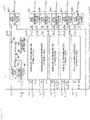
- the control device 109 includes four calculation units, that is, an arm voltage command and phase command generation unit 110, a gate pulse generation unit 111, an AC voltage removal unit 112, and a carrier signal generation unit 113.
- the arm voltage command and phase command generation unit 110 has a configuration similar to that disclosed in Patent Literature 1, and the invention can be applied regardless of the configuration of this portion, and thus detailed description of the arm voltage command and phase command generation unit 110 is omitted.
- the arm voltage command and phase command generation unit 110 can be implemented freely as long as the arm voltage command and phase command generation unit 110 has a function capable of generating an arm voltage command and a phase command.
- the gate pulse generation unit 111, the AC voltage removal unit 112, and the carrier signal generation unit 113 will be mainly described.
- FIG. 3 is a diagram showing a circuit configuration example of the gate pulse generation unit 111. An operation of the gate pulse generation unit 111 will be described with reference to FIG. 3 .
- the gate pulse generation unit 111 uses arm voltage command values VUP*, VUN*, VVP*, VVN*, VWP*, and VWN*, capacitor voltages VCUP_N', VCUN_N', VCVP_N', VCVN_N', VCWP_N', and VCWN_N', a current phase angle ⁇ i, and a triangular wave carrier signal VCar* as input signals.
- the gate pulse generation unit 111 outputs gate commands gUP_N, gUN_N, gVP_N, gVN_N, gWP_N, and gWN_N to be supplied to the unit converters.
- an input of a modulated wave generator 301UP includes one arm voltage command value VUP* and N capacitor voltages VCUP, which indicates that a comparison result is obtained for each of the plurality of unit converters that forms the arm converter in a comparison processing inside the modulated wave generator 301UP.
- a modulated wave generator 301 and a gate pulse generator 302 will be described.
- the modulated wave generator 301UP and a gate pulse generator 302UP at a U phase P side will be described, and the other modulated wave generators 301VP, 301WP, 301UN, 301VN, and 301WN and gate pulse generators 302VP, 302WP, 302UN, 302VN, and 302WN have the same configurations as configurations of the modulated wave generator 301UP and the gate pulse generator 302UP, and thus description thereof is omitted.
- the modulated wave generator 301UP causes an average value calculation unit 303 to calculate an average value VCUPave of the N capacitor voltages VCUP_N' for unit converters in an arm.
- a modulated wave VUP_N* is output according to Formula (1) by using the average value VCUPave.
- V UP _ N ⁇ V UP ⁇ + Gain V CUPave ⁇ V CUP _ N ′ ⁇ cos ⁇ i
- the right second term in Formula (1) is a term of an inter-stage balance control, and is a correction term for reducing a differential voltage between a capacitor voltage average value and a capacitor voltage of a target unit converter.
- a current phase angle ⁇ i is used.
- a control gain 308 is, for example, a proportional gain.
- the modulated wave generator 301UP shown in FIG. 3 has a specific circuit configuration for generating a modulated wave, 305 and 309 denote a subtractor or an adder, 307 denotes a multiplier, and 306 denotes a function calculator. Calculation functions of the above units can be implemented according to Formula (1).
- This processing is executed to obtain an individual modulated wave VUP_N* corresponding to polarity and magnitude of a difference between a capacitor voltage average value and a capacitor voltage of an individual unit converter.
- this control result acts such that the capacitor voltage of an individual unit converter comes close to the capacitor voltage average value and does not deviate greatly.
- the invention reduces a differential voltage between capacitor voltages of target unit converters.
- the gate pulse generator 302UP calculates a gate command gUP_N to be supplied to a unit converter of an arm.
- the gate command instructs to compare magnitude of the modulated wave VUP_N* with magnitude of the triangular wave VCar*, and the gate command instructs to perform a control such that the gate command gUP_N is turned on when VUP_N* > VCar*, and the gate command gUP_N is turned off when VUP_N* ⁇ VCar*.
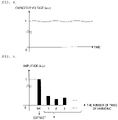
- FIG. 4 is a diagram showing a temporal fluctuation of the capacitor voltage VCUP_N
- FIG. 5 is a diagram showing components of the capacitor voltage VCUP_N.
- the actually measured capacitor voltage VCUP_N fluctuates with time as shown in FIG. 4 , and includes an AC component, so that a fundamental wave and a harmonic are cut out and only a DC component is derived as shown in FIG. 5 .
- the configuration of the AC voltage removal unit 112 is not limited as long as only a DC component can be extracted, and a typical example is introduced here.
- FIG. 6 is a diagram showing a circuit configuration example of the AC voltage removal unit 112.
- the AC voltage removal unit 112 shown in FIG. 6 includes six AC voltage removal calculation units 401 for each arm, uses 6N capacitor voltages, the rotation phase angle ⁇ of the rotating machine 101, and a rotation phase angle threshold ⁇ th as inputs, and outputs 6N capacitor voltages VCUP_N' from which AC voltage components were removed.
- FIG. 7 is a sequence diagram showing an operation example of the AC voltage removal unit 112. An operation of an AC voltage removal calculation unit 401UP_1 will be described with reference to FIG. 7 .
- the first cell 401UP_1 at a U phase P side arm is described as an example, and the similar operation applies to AC voltage removal calculation of the other unit converters.
- FIG. 7 shows temporal fluctuations of a rotation phase angle ⁇ of the rotating machine 101, a capacitor voltage VCUP_1, a capacitor voltage integrated value ⁇ VCUP_1, the number of times of integration NCUP_1, and a capacitor voltage VCUP_1' after removal of an AC voltage component from the top.
- the rotation phase angle ⁇ of the rotating machine 101 rotates from 0 [rad] to 2 ⁇ [rad].
- the capacitor voltage VCUP_1 fluctuates by repeating charging and discharging at a cycle determined by an output AC frequency.
- the calculation period t0 is a calculation period of a condition under which the rotation phase angle ⁇ of the rotating machine 101 is smaller than the rotation phase angle threshold ⁇ th.
- the integrated value ⁇ VCUP_1 of the capacitor voltage VCUP_1 is updated by adding the capacitor voltage VCUP_1 at each calculation time of the control device 109.
- NCUP_1 The number of times of integration NCUP_1 is updated by adding "+1" at each calculation time of the control device 109.
- the capacitor voltage VCUP_1' after the removal of the AC voltage component is maintained at a previous update value until the rotation phase angle ⁇ of the rotating machine 101 is larger than the rotation phase angle threshold ⁇ th.
- the calculation period t1 is a calculation period in which it is detected that the rotation phase angle ⁇ of the rotating machine 101 is larger than the rotation phase angle threshold ⁇ th.
- the integrated value ⁇ VCUP_1 of the capacitor voltage VCUP_1 in the calculation period t1 is divided by the number of times of integration NCUP_1 in the calculation period t1 so as to calculate the capacitor voltage VCUP_1' after the removal of the AC voltage component and update a value of the capacitor voltage VCUP_1'. After the value of VCUP_1' is updated, the integrated value ⁇ VCUP_1 of the capacitor voltage VCUP_1 and the number of times of integration NCUP_1 are reset.
- the calculation period t2 is a calculation period from when it is detected that the rotation phase angle ⁇ is larger than the rotation phase angle threshold ⁇ th up to a next time when it is detected that the rotation phase angle ⁇ is larger than the rotation phase angle threshold ⁇ th.
- the operation in the calculation period t2 is the same as the operation in the calculation period t1, and the integrated value ⁇ VCUP_1 and the number of times of integration NCUP_1 are updated.
- the capacitor voltage VCUP_1' By repeatedly performing the above calculation, it is possible to obtain the capacitor voltage VCUP_1' from which an output AC frequency included in a capacitor voltage is removed. Since the capacitor voltage VCUP_1' from which the output AC frequency is removed is used as a capacitor voltage of an inter-stage balance control, it is possible to remove a voltage fluctuation which causes divergence of the balance control, and it is possible to stably perform the inter-stage balance control.
- ⁇ th may be selected to update the VCUP_1' for a plurality of times in one cycle.
- ⁇ th may be selected so that the VCUP_1' is updated once in two cycles or three cycles.
- the operation of the AC voltage removal unit 112 described above is equivalent to automatically adjusting a time constant of an AC voltage filter for removing an AC component included in a capacitor voltage in accordance with a phase of the rotating machine.
- FIG. 8 is a diagram showing a circuit configuration example of the carrier signal generation unit 113 of the power conversion device 104a.
- the carrier signal generation unit 113 uses the rotation phase angle ⁇ of the rotating machine 101 as an input and outputs a triangular wave carrier signal VCar*.
- an angular frequency converter 601 shown in FIG. 8 converts the rotation phase angle ⁇ of the rotating machine 101 into an angular frequency ⁇
- a pulse number calculator 602 outputs a pulse number P corresponding to the angular frequency ⁇ .
- the carrier signal generation unit 113 generates a triangular wave corresponding to a carrier phase ⁇ c.
- the triangular wave is generated according to Formula (3) for a k-th unit converter of an arm having N unit converters, so that a phase is shifted by 2n/N for each unit converter.
- V car ⁇ 1 ⁇ 1 ⁇ cos ⁇ 1 cos ⁇ c ⁇ 2 ⁇ k N
- cos-1 is defined so as to take a value from 0 to ⁇ .
- the carrier signal generation unit 113 in FIG. 8 has a specific circuit configuration for generating a triangular wave, 603 and 607 denote a multiplier, 604 and 608 denote a subtractor, and 605 and 606 denote a function calculator.
- FIG. 9 shows input and output characteristics of the pulse number calculator 602.
- the pulse number calculator 602 outputs the pulse number P corresponding to a rotation angular frequency ⁇ of the rotating machine 101 which is an input.
- orate is defined as a rated rotation angular frequency of the rotating machine 101.
- Prate is defined as a rated pulse number.
- the pulse number calculator 602 operates such that the pulse number P is output at a constant value of 100% (Prate) in an operation range in which the angular frequency ⁇ has a value from 80% (0.8 ⁇ ⁇ rate) to 100% (orate) of the rated angular frequency ⁇ rate, and the pulse number P is output at a value larger than 100% (Prate) in an operation range in which the angular frequency ⁇ is smaller than 80% of the rated angular frequency ⁇ rate.
- increasing the pulse number P refers to increasing a PWM frequency.
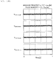
- FIG. 10A shows a capacitor voltage of a unit converter in a case where the angular frequency ⁇ is 70% of the rated angular frequency ⁇ rate (0.7 ⁇ ⁇ rate), and FIG. 10B shows a capacitor voltage of a unit converter in a case where the angular frequency ⁇ is 100% ( ⁇ rate).
- Driving is performed in a case where the pulse number P is the rated pulse number Prate.
- FIGS. 10A and 10B show a case where the arm converter 105UP includes four unit converters, and the top one is a first unit converter and the bottom one is a fourth unit converter.
- a horizontal axis represents time, and shows a waveform for a total of one second.
- FIGS. 10A and 10B when the frequency ⁇ is 70% of the rated angular frequency orate ( FIG. 10A ), a voltage imbalance among four capacitor voltages increases.
- the frequency ⁇ is the rated angular frequency ⁇ rate ( FIG. 10B )
- a voltage balance of the capacitor voltages can be ensured.
- a reason why the voltage imbalance is caused only when the frequency ⁇ is 70% of the rated angular frequency orate ( FIG. 10A ) is that the number of control times of the inter-stage balance control per unit time is reduced and the inter-stage balance control becomes unstable.
- FIG. 11A shows a capacitor voltage in a case where the angular frequency ⁇ is 70% of the rated angular frequency ⁇ rate (0.7 ⁇ ⁇ rate) and the pulse number P is 100% (Prate)
- FIG. 11B shows a capacitor voltage in a case where the angular frequency ⁇ is 70% of the rated angular frequency ⁇ rate (0.7 ⁇ ⁇ rate) and the pulse number P is 130% of the rated pulse number Prate (1.3 ⁇ Prate).
- FIGS. 11A and 11B when the pulse number P is the rated pulse number Prate ( FIG. 11A ), a voltage imbalance among capacitor voltages increases, and when the pulse number P is 130% of the rated pulse number Prate ( FIG. 11B ), the capacitor voltages are balanced. That is, as can be seen from FIG. 9 , when an operation is performed at the angular frequency ⁇ smaller than the rated angular frequency ⁇ rate, the inter-stage balance control can be stabilized and the balance of the capacitor voltages can be maintained by setting the pulse number P to be larger than the rated pulse number Prate.
- capacitor voltages of unit converters can be balanced even at the time of starting the rotating machine or under an operation condition in which an output AC frequency is low, it is possible to implement the DSMMC converter using a capacitor having the same electrostatic capacitance as that in a case of driving at the rated output AC frequency.
- the inter-stage balance control can be stabilized and an output current can be increased at the time of starting the rotating machine, a starting torque can be easily ensured.
Landscapes
- Engineering & Computer Science (AREA)
- Power Engineering (AREA)
- Inverter Devices (AREA)
Abstract
Description
- The present invention relates to a control device of a frequency converter and a control method of a frequency converter including a modular multilevel converter (hereinafter referred to as an MMC converter), and a control device of a variable speed pumped storage power generation system.
- An MMC converter includes a voltage source such as a capacitor and a storage battery that are energy storage elements, and a unit converter including a half-bridge circuit. The unit converter generates a desired voltage by controlling a PWM modulation factor of the half-bridge circuit. Voltages of the capacitor and the storage battery that are energy storage elements fluctuate by repeating charging and discharging at a cycle determined by an output AC frequency of the MMC converter.
- A plurality of sets of the unit converters are connected in series to form a two-terminal arm converter, first terminals of the arm converter are connected to respective phase terminals of an AC power source, and a star-connected second terminal is connected to a terminal of a DC power source.
- The arm converter connected to the respective phases as described above generates a desired AC voltage to perform an AC current control, and at the same time, superimposes a DC current to implement a power conversion with the DC power source.
- A control of the MMC converter includes a function (hereinafter, referred to as an inter-stage balance control) of balancing an average voltage of capacitors between unit converters by a current control of adjusting an arm current to an AC current command and a DC current command from the outside and by mutually adjusting PWM modulation factors of half-bridge circuits provided in the unit converters in an arm, and a function (hereinafter, referred to as an inter-phase balance control) of balancing total accumulated energy of capacitors in arm converters between the arm converters. In order to implement the inter-phase balance control, a circuit element for preventing a circulating current between the arm converters is required.
-
Patent Literature 1 proposes to provide a circulating current prevention reactor between a first terminal of an arm converter and a terminal of an AC power source for the purpose of preventing a circulating current. A device disclosed inPatent Literature 1 forms a double star type MMC converter (hereinafter referred to as a DSMMC converter) which is one form of an MMC converter. - Non-Patent Literature 1 discloses a device in which DC terminals of two DSMMC converters are back-connected to form a frequency converter, one terminal of an AC power source is connected to a power system, and the other terminal of the AC power source is connected to a rotating machine. According to the device disclosed in the Non-Patent
Literature 1, since a DC current is not superimposed on the rotating machine even when the rotating machine is connected to an MMC converter, the device is suitable for a case of a variable speed rotating machine that is directly connected to a power system and operates at a constant frequency. - PTL 1:
Japanese Patent NO. 5775033 - Non-Patent Literature 1: Makoto Hagiwara, Kazutoshi Nishimura, Hirofumi Akagi "A High-Voltage Motor Drive with a Modular Multilevel PWM Inverter Part I. Experimental Verification by a 400-V, 15-kW Downscaled Model", IEEJ Transactions on Industry Applications, Apr. 2010, Vol. 130, NO. 4, pp. 544-551
- The invention relates to a frequency converter (a power conversion device) including two DSMMC converters, and particularly relates to a DSMMC converter connected to a rotating machine.
- A first problem in a case of configuring the frequency converter (the power conversion device) with a DSMMC converter connected to the rotating machine is that an output current of the DSMMC converter is limited as an output AC frequency decreases, and a starting torque at the time of starting the rotating machine cannot be ensured. A voltage fluctuation amount of an energy storage element of a unit converter in the DSMMC converter is proportional to the output current and is inversely proportional to the output AC frequency. That is, when the output current of the DSMMC converter is constant, a voltage fluctuation of the energy storage element at the time of starting is increased. The voltage fluctuation of the energy storage element is a disturbance for an inter-stage balance control and causes divergence of the balance control. Therefore, at the time of starting, it is required to limit the output current in order to reduce a fluctuation of a capacitor voltage, and the starting torque at the time of starting the rotating machine cannot be ensured. The first problem is a problem common to an MMC converter connected to a rotating machine, and the Non-Patent Literature 1 does not disclose such a problem and a solution to such a problem.
- In order to solve the first problem, a configuration can be conceived in which a capacity of the energy storage element is increased so as to sufficiently reduce the voltage fluctuation at the time of starting without limiting the output current. However, in order to economically implement the DSMMC converter connected to the rotating machine, it is desirable that the rotating machine can be started with the same capacity as that in a case where an energy storage element of each unit converter is driven at a rated output AC frequency.
- A second problem in a case of configuring the frequency converter (the power conversion device) with the DSMMC converter connected to the rotating machine is that the inter-stage balance control is likely to become unstable at the time of starting and under an operation condition of a low output AC frequency. In order to implement the DSMMC converter with high efficiency, it is desirable to drive the DSMMC converter at a PWM frequency synchronized with the output AC frequency. However, since the number of times of the inter-stage balance control per unit time is reduced as the PWM frequency decreases, control performance of the inter-stage balance control deteriorates and the inter-stage balance control is likely to become unstable.
- With regard to the second problem, Non-Patent
Literature 1 discloses that an operation is performed at a PWM frequency of 1 kHz and does not disclose the second problem. In order to implement the MMC converter with high efficiency, it is desirable that the MMC converter can be driven at a smaller PWM frequency. - In view of the above problems, an object of the invention is to provide a control device of a frequency converter, a control method of a frequency converter, and a control device of a variable speed pumped storage power generation system that can maintain a voltage balance using a high-efficiency and small-capacity energy storage element even in the case of a low output AC frequency.
- In order to achieve the above object, the invention provides a control device of a frequency converter in which a rotating machine including a synchronous machine is interconnected to a power system. The frequency converter includes a plurality of sets of arms in which a plurality of unit converters are connected in series, capacitors are connected in parallel in the plurality of unit converters, one ends of the series connected unit converters are connected to respective phases of an alternating current, and the other ends of the series connected unit converters are connected to terminals of a direct current. The control device includes an AC voltage removal calculation unit configured to detect at least voltages of the capacitors in the plurality of unit converters that form the arms, extract a DC component from the capacitor voltages, and input the DC component; an arm voltage command generation unit configured to generate an arm voltage command value; a carrier signal generation unit configured to generate a carrier signal; and a gate pulse generation unit that is provided with a modulated wave generator configured to correct the arm voltage command value to be supplied by the arm voltage command generation unit and that uses the corrected arm voltage command value and the carrier signal to determine a gate command for each of the plurality of unit converters in respective arms. The modulated wave generator uses the DC component calculated in the AC voltage removal calculation unit to correct the arm voltage command value so that magnitude of the voltages of the capacitors in the unit converters of the arms does not fluctuate.
- The invention further provides a control device of a variable speed pumped storage power generation system in which a rotating machine including a synchronous machine connected to a pump water wheel is interconnected to a power system via a frequency converter. The frequency converter includes a plurality of sets of arms in which a plurality of unit converters are connected in series, capacitors are connected in parallel in the plurality of unit converters, one ends of the series connected unit converters are connected to respective phases of an alternating current, and the other ends of the series connected unit converters are connected to terminals of a direct current. The control device includes an AC voltage removal calculation unit configured to detect at least voltages of the capacitors in the plurality of unit converters that form the arms, extract a DC component from the capacitor voltages, and input the DC component; an arm voltage command generation unit configured to generate an arm voltage command value; a carrier signal generation unit configured to generate a carrier signal; and a gate pulse generation unit that is provided with a modulated wave generator configured to correct the arm voltage command value to be supplied by the arm voltage command generation unit and that uses the corrected arm voltage command value and the carrier signal to determine a gate command for each of the plurality of unit converters in respective arms. The modulated wave generator uses the DC component calculated in the AC voltage removal calculation unit to correct the arm voltage command value so that magnitude of the voltages of the capacitors in the unit converters of the arms does not fluctuate.
- The invention further provides a control method of a frequency converter in which a rotating machine including a synchronous machine is interconnected to a power system. The frequency converter includes a plurality of sets of arms in which a plurality of unit converters are connected in series, capacitors are connected in parallel in the plurality of unit converters, one ends of the series connected unit converters are connected to respective phases of an alternating current, and the other ends of the series connected unit converters are connected to terminals of a direct current. The control method includes detecting at least voltages of the capacitors in the plurality of unit converters that form the arms and extracting a DC component from the capacitor voltages, comparing an arm voltage command value and a carrier signal, and determining a gate command for each of the plurality of unit converters in respective arms, using the DC component to correct the arm voltage command value so that magnitude of voltages of the capacitors in respective unit converters of the arms does not fluctuate, and comparing the corrected arm voltage command value and the carrier signal.
- According to the invention, since it is possible to increase an output current at the time of starting, it is possible to ensure a starting torque at the time of starting the rotating machine. In addition, it is possible to balance voltages of energy storage elements in respective unit converters at the time of starting and under an operation condition of a low output AC frequency.
- Therefore, it is possible to implement a DSMMC converter capable of starting the rotating machine with the same capacity as that in a case where an energy storage element is driven at a rated output AC frequency.
-
- [
FIG. 1] FIG. 1 is a diagram showing a configuration example of a variable speed pumped storage power generation system and a control device of the variable speed pumped storage power generation system according to an embodiment of the invention. - [
FIG. 2] FIG. 2 is a diagram showing a circuit configuration example of an arm converter 105 according to the embodiment of the invention. - [
FIG. 3] FIG. 3 is a diagram showing a circuit configuration example of a gatepulse generation unit 111. - [
FIG. 4] FIG. 4 is a diagram showing a temporal fluctuation of an actually measured capacitor voltage VCUP_N. - [
FIG. 5] FIG. 5 is a diagram showing components of the capacitor voltage VCUP_N. - [
FIG. 6] FIG. 6 is a diagram showing a circuit configuration example of an ACvoltage removal unit 112. - [
FIG. 7] FIG. 7 is a sequence diagram showing an operation example of the ACvoltage removal unit 112. - [
FIG. 8] FIG. 8 is a diagram showing a circuit configuration example of a carriersignal generation unit 113. - [
FIG. 9] FIG. 9 shows input and output characteristics of a pulse number calculator according to the embodiment of the invention. - [
FIG. 10A] FIG. 10A is a diagram showing an example of a capacitor voltage waveform when an angular frequency of a rotating machine is 70% of a rated angular frequency. - [
FIG. 10B] FIG. 10B is a diagram showing an example of a capacitor voltage waveform when the angular frequency of the rotating machine is the rated angular frequency. - [
FIG. 11A] FIG. 11A is a diagram showing an example of a capacitor voltage waveform when driving is performed in a case where an angular frequency ω is 70% of the rated angular frequency and the pulse number P is 100%. - [
FIG. 11B] FIG. 11B is a diagram showing an example of a capacitor voltage waveform when driving is performed in a case where the angular frequency ω is 70% of the rated angular frequency and the pulse number P is 130%. - Hereinafter, embodiments of the invention will be described with reference to the drawings. A control device of a power conversion device according to the invention can be widely applied to a general power conversion field. Here, a case where the power conversion device is applied as a frequency conversion device of a variable speed pumped storage power generation system will be described in detail as an example, and the invention is not limited by the present embodiment.
-
FIG. 1 shows a configuration example of a variable speed pumped storage power generation system and a control device of the variable speed pumped storage power generation system according to an embodiment of the invention. InFIG. 1 , a configuration of a main circuit is shown in an upper part, and a configuration of a control device is shown in a lower part. First, description will be given from a main circuit side. - In the variable speed pumped storage power generation system, a rotating
machine 101 is interconnected to apower system 102 via afrequency converter 103. - The
rotating machine 101 is generally a power generator, a motor, or a power generation motor that is configured with a synchronous machine. In the present specification, the above machines are collectively referred to as a power generation motor. In the case of a variable speed pumped storage power generation system, the rotatingmachine 101 is a power generation motor whose shaft is connected to a pump water wheel. In a pumping operation mode, the rotatingmachine 101 receives power from the power system, operates as a motor, and performs a pumping operation. In a power generation mode, the rotatingmachine 101 is driven by a water wheel, operates as a power generator, and transmits power to the power system. In order to control the variable speed pumped storage power generation system which will be described later, aphase detector 108 is provided, and a rotation phase angle θ of therotating machine 101 is detected and transmitted to acontrol device 109. - The conversion of power and a frequency of the variable speed pumped storage power generation system is performed by the
frequency converter 103. Thefrequency converter 103 is implemented by back-connecting twopower conversion devices power conversion device 104a is implemented by a DSMMC converter. The invention is targeted on thepower conversion device 104a connected to therotating machine 101, and a circuit configuration of the otherpower conversion device 104b may be implemented by a DSMMC converter or other power conversion circuits. By adopting such a configuration, it is possible to control a frequency of anAC system 102 and a frequency and a speed of therotating machine 101 to have values independent of each other. - A main circuit of the
power conversion device 104a includes six sets of arms formed between respective U, V, and W phase terminals indicating three-phase AC terminals of therotating machine 101 and positive and negative DC terminals indicated by P and N. An arm converter 105 and a circulating current prevention reactor 106 are connected in series on each arm, and further, a current detector 107 controls the variable speed pumped storage power generation system to be described later. The current detector 107 detects an arm current I of each phase and transmits the arm current I to thecontrol device 109. - In the following description, an alphabetic symbol U, V, W, P, and N may be attached to a component reference number (for example, 105) for the purpose of distinguishing an arm, a device in an arm, or the like. According to this example, it can be said that the main circuit of the
power conversion device 104a shown inFIG. 1 includes six arm converters 105UP, 105UN, 105VP, 105VN, 105WP, and 105WN each having two output terminals of an a terminal and a b terminal, six circulating current prevention reactors 106UP, 106UN, 106VP, 106VN, 106WP, and 106WN, and six current detectors 107UP, 107UN, 107VP, 107VN, 107WP, and 107WN that respectively detect arm currents IUP, IUN, IVP, IVN, IWP, and IWN of respective phases. A rule for assigning a symbol is first assigning a symbol of an AC side terminal after a reference number and then assigning a symbol of a DC side terminal after the reference number. It is possible to determine an arm among the six arms based on this rule. - Next, the arm converter 105 will be described. The arm converter 105 includes two output terminals, that is, an a terminal at an AC connection side and a b terminal at a DC connection side. The b terminals of the arm converters 105UP, 105VP, and 105WP and the a terminals of 105UN, 105VN, and 105WN are connected to terminals (a U terminal, a V terminal, and a W terminal) of an AC power source via the circulating current prevention reactors 106UP, 106UN, 106VP, 106VN, 106WP, and 106WN. The a terminals of the arm converters 105UP, 105VP, and 105WP and the b terminals of the arm converters 105UN, 105VN, and 105WN are connected to terminals (a P terminal and an N terminal) of a DC and are connected to the
power conversion device 104b on the other side. -
FIG. 2 is a diagram showing a circuit configuration example of the arm converter 105 according to the embodiment of the invention. Hereinafter, the arm converter 105UP will be representatively described. Since the other arm converters 105UN, 105VP, 105VN, 105WP, and 105WN have the similar configuration, description of the other arm converters is omitted. - The arm converter 105UP is a circuit in which N unit converters 200_1 to 200_N are connected in series. The unit converters in
FIG. 2 use a half-bridge circuit, and N is the number of unit converters in each arm converter. In a unit converter, aswitching circuit 203 in which two switchingelements capacitor 204 serving as an energy storage element, and avoltage detector 205 are connected in parallel. - In addition, a
cell control device 206 and twogate drive circuits 207 are provided. An a terminal and a b terminal inFIG. 2 are output terminals of the arm converter 105UP, and correspond to the a terminal and the b terminal of an arm converter inFIG. 1 . - The
voltage detector 205 detects a capacitor voltage of the unit converter 200, and transmits detected capacitor voltages VCUP_1 to VCUP_N to thecell control devices 206 of respective unit converters. - The
cell control device 206 provided for eachunit converter 203 distributes gate commands gUP_1 to gUP_N of the unit converter 200 output from thecontrol device 109 shown inFIG. 1 to thegate drive circuit 207. In addition, the capacitor voltages VCUP_1 to VCUP_N are output to thecontrol device 109. - The
gate drive circuit 207 generates a gate drive signal for switching on and off of the switchingelements elements - Next, the
control device 109 will be described with reference toFIGS. 1 ,3 , and4 . - The
control device 109 shown inFIG. 1 uses, as an input, the arm currents IUP, IUN, IVP, IVN, IWP, and IWN, the rotation phase θ of therotating machine - The
control device 109 includes four calculation units, that is, an arm voltage command and phasecommand generation unit 110, a gatepulse generation unit 111, an ACvoltage removal unit 112, and a carriersignal generation unit 113. The arm voltage command and phasecommand generation unit 110 has a configuration similar to that disclosed inPatent Literature 1, and the invention can be applied regardless of the configuration of this portion, and thus detailed description of the arm voltage command and phasecommand generation unit 110 is omitted. In short, the arm voltage command and phasecommand generation unit 110 can be implemented freely as long as the arm voltage command and phasecommand generation unit 110 has a function capable of generating an arm voltage command and a phase command. In the present embodiment, the gatepulse generation unit 111, the ACvoltage removal unit 112, and the carriersignal generation unit 113 will be mainly described. -
FIG. 3 is a diagram showing a circuit configuration example of the gatepulse generation unit 111. An operation of the gatepulse generation unit 111 will be described with reference toFIG. 3 . The gatepulse generation unit 111 uses arm voltage command values VUP*, VUN*, VVP*, VVN*, VWP*, and VWN*, capacitor voltages VCUP_N', VCUN_N', VCVP_N', VCVN_N', VCWP_N', and VCWN_N', a current phase angle θi, and a triangular wave carrier signal VCar* as input signals. The gatepulse generation unit 111 outputs gate commands gUP_N, gUN_N, gVP_N, gVN_N, gWP_N, and gWN_N to be supplied to the unit converters. - In
FIGS. 1 ,3 , and the like, a portion in which a diagonal line is disposed in a line indicating an input or an output and that is denoted by N indicates that the similar processing such as input, output, and the like is performed on N unit converters, and N is the number of a plurality of unit converters that forms an arm converter. Therefore, for example, an input of a modulated wave generator 301UP includes one arm voltage command value VUP* and N capacitor voltages VCUP, which indicates that a comparison result is obtained for each of the plurality of unit converters that forms the arm converter in a comparison processing inside the modulated wave generator 301UP. - First, operations and functions of a modulated wave generator 301 and a gate pulse generator 302 will be described. In the present invention, the modulated wave generator 301UP and a gate pulse generator 302UP at a U phase P side will be described, and the other modulated wave generators 301VP, 301WP, 301UN, 301VN, and 301WN and gate pulse generators 302VP, 302WP, 302UN, 302VN, and 302WN have the same configurations as configurations of the modulated wave generator 301UP and the gate pulse generator 302UP, and thus description thereof is omitted.
- The modulated wave generator 301UP causes an average
value calculation unit 303 to calculate an average value VCUPave of the N capacitor voltages VCUP_N' for unit converters in an arm. A modulated wave VUP_N* is output according to Formula (1) by using the average value VCUPave.
[Formula 1]
- Here, the right second term in Formula (1) is a term of an inter-stage balance control, and is a correction term for reducing a differential voltage between a capacitor voltage average value and a capacitor voltage of a target unit converter.
- In order to create a correction term in accordance with a sign of a current, a current phase angle θi is used. A
control gain 308 is, for example, a proportional gain. The modulated wave generator 301UP shown inFIG. 3 has a specific circuit configuration for generating a modulated wave, 305 and 309 denote a subtractor or an adder, 307 denotes a multiplier, and 306 denotes a function calculator. Calculation functions of the above units can be implemented according to Formula (1). - This processing is executed to obtain an individual modulated wave VUP_N* corresponding to polarity and magnitude of a difference between a capacitor voltage average value and a capacitor voltage of an individual unit converter. As will be clear from a control to be described later, this control result acts such that the capacitor voltage of an individual unit converter comes close to the capacitor voltage average value and does not deviate greatly. The invention reduces a differential voltage between capacitor voltages of target unit converters.
- The gate pulse generator 302UP calculates a gate command gUP_N to be supplied to a unit converter of an arm. The gate command instructs to compare magnitude of the modulated wave VUP_N* with magnitude of the triangular wave VCar*, and the gate command instructs to perform a control such that the gate command gUP_N is turned on when VUP_N* > VCar*, and the gate command gUP_N is turned off when VUP_N* < VCar*.
- Next, a function and an operation of the AC
voltage removal unit 112 which is a central part of the invention will be described. First,FIG. 4 is a diagram showing a temporal fluctuation of the capacitor voltage VCUP_N, andFIG. 5 is a diagram showing components of the capacitor voltage VCUP_N. - In the AC
voltage removal unit 112, the actually measured capacitor voltage VCUP_N fluctuates with time as shown inFIG. 4 , and includes an AC component, so that a fundamental wave and a harmonic are cut out and only a DC component is derived as shown inFIG. 5 . The configuration of the ACvoltage removal unit 112 is not limited as long as only a DC component can be extracted, and a typical example is introduced here. -
FIG. 6 is a diagram showing a circuit configuration example of the ACvoltage removal unit 112. The ACvoltage removal unit 112 shown inFIG. 6 includes six AC voltage removal calculation units 401 for each arm, uses 6N capacitor voltages, the rotation phase angle θ of therotating machine 101, and a rotation phase angle threshold θth as inputs, and outputs 6N capacitor voltages VCUP_N' from which AC voltage components were removed. -
FIG. 7 is a sequence diagram showing an operation example of the ACvoltage removal unit 112. An operation of an AC voltage removal calculation unit 401UP_1 will be described with reference toFIG. 7 . InFIG. 7 , the first cell 401UP_1 at a U phase P side arm is described as an example, and the similar operation applies to AC voltage removal calculation of the other unit converters. -
FIG. 7 shows temporal fluctuations of a rotation phase angle θ of therotating machine 101, a capacitor voltage VCUP_1, a capacitor voltage integrated value ΣVCUP_1, the number of times of integration NCUP_1, and a capacitor voltage VCUP_1' after removal of an AC voltage component from the top. The rotation phase angle θ of therotating machine 101 rotates from 0 [rad] to 2π [rad]. The capacitor voltage VCUP_1 fluctuates by repeating charging and discharging at a cycle determined by an output AC frequency. - First, a calculation period t0 will be described. The calculation period t0 is a calculation period of a condition under which the rotation phase angle θ of the
rotating machine 101 is smaller than the rotation phase angle threshold θth. - The integrated value ΣVCUP_1 of the capacitor voltage VCUP_1 is updated by adding the capacitor voltage VCUP_1 at each calculation time of the
control device 109. - The number of times of integration NCUP_1 is updated by adding "+1" at each calculation time of the
control device 109. The capacitor voltage VCUP_1' after the removal of the AC voltage component is maintained at a previous update value until the rotation phase angle θ of therotating machine 101 is larger than the rotation phase angle threshold θth. - Next, an operation in a calculation period t1 will be described. The calculation period t1 is a calculation period in which it is detected that the rotation phase angle θ of the
rotating machine 101 is larger than the rotation phase angle threshold θth. - The integrated value ΣVCUP_1 of the capacitor voltage VCUP_1 in the calculation period t1 is divided by the number of times of integration NCUP_1 in the calculation period t1 so as to calculate the capacitor voltage VCUP_1' after the removal of the AC voltage component and update a value of the capacitor voltage VCUP_1'. After the value of VCUP_1' is updated, the integrated value ΣVCUP_1 of the capacitor voltage VCUP_1 and the number of times of integration NCUP_1 are reset.
- Next, an operation in a calculation period t2 will be described. The calculation period t2 is a calculation period from when it is detected that the rotation phase angle θ is larger than the rotation phase angle threshold θth up to a next time when it is detected that the rotation phase angle θ is larger than the rotation phase angle threshold θth. The operation in the calculation period t2 is the same as the operation in the calculation period t1, and the integrated value ΣVCUP_1 and the number of times of integration NCUP_1 are updated.
- By repeatedly performing the above calculation, it is possible to obtain the capacitor voltage VCUP_1' from which an output AC frequency included in a capacitor voltage is removed. Since the capacitor voltage VCUP_1' from which the output AC frequency is removed is used as a capacitor voltage of an inter-stage balance control, it is possible to remove a voltage fluctuation which causes divergence of the balance control, and it is possible to stably perform the inter-stage balance control.
- Here, although VCUP_1' in
FIG. 7 is updated only once in one cycle, θth may be selected to update the VCUP_1' for a plurality of times in one cycle. In addition, instead of updating VCUP_1' once in one cycle, θth may be selected so that the VCUP_1' is updated once in two cycles or three cycles. - The operation of the AC
voltage removal unit 112 described above is equivalent to automatically adjusting a time constant of an AC voltage filter for removing an AC component included in a capacitor voltage in accordance with a phase of the rotating machine. -
FIG. 8 is a diagram showing a circuit configuration example of the carriersignal generation unit 113 of thepower conversion device 104a. InFIG. 8 , the carriersignal generation unit 113 uses the rotation phase angle θ of therotating machine 101 as an input and outputs a triangular wave carrier signal VCar*. Specifically, first, anangular frequency converter 601 shown inFIG. 8 converts the rotation phase angle θ of therotating machine 101 into an angular frequency ω, and apulse number calculator 602 outputs a pulse number P corresponding to the angular frequency ω. - The carrier
signal generation unit 113 generates a triangular wave corresponding to a carrier phase θc. The carrier phase θc is calculated according to Formula (2).
[Formula 2]
- For example, the triangular wave is generated according to Formula (3) for a k-th unit converter of an arm having N unit converters, so that a phase is shifted by 2n/N for each unit converter.
[Formula 3]
- In Formula (3), cos-1 is defined so as to take a value from 0 to π. The carrier
signal generation unit 113 inFIG. 8 has a specific circuit configuration for generating a triangular wave, 603 and 607 denote a multiplier, 604 and 608 denote a subtractor, and 605 and 606 denote a function calculator. -
FIG. 9 shows input and output characteristics of thepulse number calculator 602. Thepulse number calculator 602 outputs the pulse number P corresponding to a rotation angular frequency ω of therotating machine 101 which is an input. InFIG. 9 , orate is defined as a rated rotation angular frequency of therotating machine 101. Prate is defined as a rated pulse number. - In
FIG. 9 , thepulse number calculator 602 operates such that the pulse number P is output at a constant value of 100% (Prate) in an operation range in which the angular frequency ω has a value from 80% (0.8 × ωrate) to 100% (orate) of the rated angular frequency ωrate, and the pulse number P is output at a value larger than 100% (Prate) in an operation range in which the angular frequency ω is smaller than 80% of the rated angular frequency ωrate. Here, increasing the pulse number P refers to increasing a PWM frequency. - Next, a reason why the pulse number P is changed in accordance with the input and output characteristics shown in
FIG. 9 will be described with reference toFIGS. 10A ,10B ,11A , and11B . -
FIG. 10A shows a capacitor voltage of a unit converter in a case where the angular frequency ω is 70% of the rated angular frequency ωrate (0.7 × ωrate), andFIG. 10B shows a capacitor voltage of a unit converter in a case where the angular frequency ω is 100% (ωrate). Driving is performed in a case where the pulse number P is the rated pulse number Prate. -
FIGS. 10A and10B show a case where the arm converter 105UP includes four unit converters, and the top one is a first unit converter and the bottom one is a fourth unit converter. A horizontal axis represents time, and shows a waveform for a total of one second. As can be seen fromFIGS. 10A and10B , when the frequency ω is 70% of the rated angular frequency orate (FIG. 10A ), a voltage imbalance among four capacitor voltages increases. On the other hand, when the frequency ω is the rated angular frequency ωrate (FIG. 10B ), a voltage balance of the capacitor voltages can be ensured. A reason why the voltage imbalance is caused only when the frequency ω is 70% of the rated angular frequency orate (FIG. 10A ) is that the number of control times of the inter-stage balance control per unit time is reduced and the inter-stage balance control becomes unstable. - Next,
FIG. 11A shows a capacitor voltage in a case where the angular frequency ω is 70% of the rated angular frequency ωrate (0.7 × ωrate) and the pulse number P is 100% (Prate), andFIG. 11B shows a capacitor voltage in a case where the angular frequency ω is 70% of the rated angular frequency ωrate (0.7 × ωrate) and the pulse number P is 130% of the rated pulse number Prate (1.3 × Prate). - As can be seen from
FIGS. 11A and11B , when the pulse number P is the rated pulse number Prate (FIG. 11A ), a voltage imbalance among capacitor voltages increases, and when the pulse number P is 130% of the rated pulse number Prate (FIG. 11B ), the capacitor voltages are balanced. That is, as can be seen fromFIG. 9 , when an operation is performed at the angular frequency ω smaller than the rated angular frequency ωrate, the inter-stage balance control can be stabilized and the balance of the capacitor voltages can be maintained by setting the pulse number P to be larger than the rated pulse number Prate. - According to the operation described above, since capacitor voltages of unit converters can be balanced even at the time of starting the rotating machine or under an operation condition in which an output AC frequency is low, it is possible to implement the DSMMC converter using a capacitor having the same electrostatic capacitance as that in a case of driving at the rated output AC frequency. In addition, since the inter-stage balance control can be stabilized and an output current can be increased at the time of starting the rotating machine, a starting torque can be easily ensured.
-
- 101: rotating machine
- 102: power system
- 103: frequency converter
- 104a, 104b: self-excited converter
- 105UP, 105UN, 105VP, 105VN, 105WP, 105WN: arm
- 106UP, 106UN, 106VP, 106VN, 106WP, 106WN: circulating current prevention reactor
- 107UP, 107UN, 107VP, 107VN, 107WP, 107WN: current detector
- 108: phase detector
- 109: control device
- 110: phase command generation unit
- 111: gate pulse generation unit
- 112: AC voltage removal unit
- 113: carrier signal generation unit
- 201, 202: switching element
- 203: switching circuit
- 204: capacitor
- 205: DC voltage detector
- 206: cell control device
- 207: gate drive circuit
- 301UP, 301UN, 301VP, 301VN, 301WP, 301WN: modulated wave generator
- 302UP, 302UN, 302VP, 302VN, 302WP, and 302WN: gate pulse generator
- 401UP, 401UN, 401VP, 401VN, 401WP, and 401WN: AC voltage removal calculation unit
- 601: angular frequency converter
- 602: pulse number calculator
Claims (7)
- A control device of a frequency converter in which a rotating machine including a synchronous machine is interconnected to a power system,the frequency converter including a plurality of sets of arms in which a plurality of unit converters are connected in series, capacitors are connected in parallel in the plurality of unit converters, one ends of the series connected unit converters are connected to respective phases of an alternating current, and the other ends of the series connected unit converters are connected to terminals of a direct current,the control device comprising:an AC voltage removal calculation unit configured to detect at least voltages of the capacitors in the plurality of unit converters that form the arms, extract a DC component from the capacitor voltages, and input the DC component;an arm voltage command generation unit configured to generate an arm voltage command value;a carrier signal generation unit configured to generate a carrier signal; anda gate pulse generation unit that is provided with a modulated wave generator configured to correct the arm voltage command value to be supplied by the arm voltage command generation unit and that uses the corrected arm voltage command value and the carrier signal to determine a gate command for each of the plurality of unit converters in respective arms, whereinthe modulated wave generator uses the DC component calculated in the AC voltage removal calculation unit to correct the arm voltage command value so that magnitude of the voltages of the capacitors in the unit converters of the arms does not fluctuate.
- The control device of a frequency converter according to claim 1, wherein
the AC voltage removal calculation unit changes a filter time constant according to a phase of the rotating machine in order to remove an AC voltage determined by a rotation frequency of the rotating machine. - The control device of a frequency converter according to claim 1, wherein
the AC voltage removal calculation unit calculates an integrated voltage obtained by integrating capacitor voltages until a desired phase threshold is reached, divides the integrated voltage by the number of times of integration to calculate an average voltage of the unit converters in a desired period, and maintains the average voltage until the phase threshold is reached for a next time, thereby removing the AC voltage. - The control device of a frequency converter according to any one of claims 1 to 3, wherein
the carrier signal generation unit determines a carrier frequency to be applied to a power conversion device based on the rotation frequency of the rotating machine, and the carrier signal generation unit has a function of preventing a voltage imbalance of the capacitor voltages by increasing a pulse number for PWM driving the frequency converter in an operation region in which the rotation frequency of the rotating machine is equal to or less than a specified value. - The control device of a frequency converter according to claim 4, wherein
the carrier signal generation unit has a function of increasing the pulse number for PWM driving the frequency converter in an operation region in which a rotation angular frequency of the rotating machine is less than 80% of a rated rotation angular frequency. - A control device of a variable speed pumped storage power generation system in which a rotating machine including a synchronous machine connected to a pump water wheel is interconnected to a power system via a frequency converter,the frequency converter including a plurality of sets of arms in which a plurality of unit converters are connected in series, capacitors are connected in parallel in the plurality of unit converters, one ends of the series connected unit converters are connected to respective phases of an alternating current, and the other ends of the series connected unit converters are connected to terminals of a direct current,the control device comprising:an AC voltage removal calculation unit configured to detect at least voltages of the capacitors in the plurality of unit converters that form the arms, extract a DC component from the capacitor voltages, and input the DC component;an arm voltage command generation unit configured to generate an arm voltage command value;a carrier signal generation unit configured to generate a carrier signal; anda gate pulse generation unit that is provided with a modulated wave generator configured to correct the arm voltage command value to be supplied by the arm voltage command generation unit and that uses the corrected arm voltage command value and the carrier signal to determine a gate command for each of the plurality of unit converters in respective arms, whereinthe modulated wave generator uses the DC component calculated in the AC voltage removal calculation unit to correct the arm voltage command value so that magnitude of the voltages of the capacitors in the unit converters of the arms does not fluctuate.
- A control method of a frequency converter in which a rotating machine including a synchronous machine is interconnected to a power system,the frequency converter including a plurality of sets of arms in which a plurality of unit converters are connected in series, capacitors are connected in parallel in the plurality of unit converters, one ends of the series connected unit converters are connected to respective phases of an alternating current, and the other ends of the series connected unit converters are connected to terminals of a direct current,the control method comprising:detecting at least voltages of the capacitors in the plurality of unit converters that form the arms and extracting a DC component from the capacitor voltages;comparing an arm voltage command value and a carrier signal; anddetermining a gate command for each of the plurality of unit converters in respective arms, using the DC component to correct the arm voltage command value so that magnitude of voltages of the capacitors in respective unit converters of the arms does not fluctuate, and comparing the corrected arm voltage command value and the carrier signal.
Applications Claiming Priority (2)
| Application Number | Priority Date | Filing Date | Title |
|---|---|---|---|
| JP2020041670A JP7425633B2 (en) | 2020-03-11 | 2020-03-11 | Control device and control method for frequency converter, and control device for variable speed pumped storage power generation system |
| PCT/JP2021/009251 WO2021182460A1 (en) | 2020-03-11 | 2021-03-09 | Control device and control method for frequency converter and control device for variable-speed pumped-storage hydroelectricity system |
Publications (3)
| Publication Number | Publication Date |
|---|---|
| EP4120542A1 true EP4120542A1 (en) | 2023-01-18 |
| EP4120542A4 EP4120542A4 (en) | 2024-05-01 |
| EP4120542B1 EP4120542B1 (en) | 2026-05-06 |
Family
ID=77671486
Family Applications (1)
| Application Number | Title | Priority Date | Filing Date |
|---|---|---|---|
| EP21768252.5A Active EP4120542B1 (en) | 2020-03-11 | 2021-03-09 | Control device for frequency converter |
Country Status (3)
| Country | Link |
|---|---|
| EP (1) | EP4120542B1 (en) |
| JP (1) | JP7425633B2 (en) |
| WO (1) | WO2021182460A1 (en) |
Families Citing this family (6)
| Publication number | Priority date | Publication date | Assignee | Title |
|---|---|---|---|---|
| JP7798509B2 (en) * | 2021-09-07 | 2026-01-14 | 株式会社三共 | gaming machines |
| JP7793315B2 (en) * | 2021-09-07 | 2026-01-05 | 株式会社三共 | gaming machines |
| US20250119035A1 (en) * | 2022-01-20 | 2025-04-10 | Hitachi Mitsubishi Hydro Corporation | Variable-speed synchronous generator-motor device |
| WO2024150437A1 (en) * | 2023-01-13 | 2024-07-18 | 日立三菱水力株式会社 | Modular multilevel power converter |
| EP4654456A1 (en) * | 2023-01-19 | 2025-11-26 | Hitachi Mitsubishi Hydro Corporation | Modular multi-level electric power converter |
| CN117869168B (en) * | 2024-01-30 | 2025-01-21 | 四川水利职业技术学院 | A speed regulator for a small hydropower station |
Family Cites Families (5)
| Publication number | Priority date | Publication date | Assignee | Title |
|---|---|---|---|---|
| JP5775033B2 (en) | 2012-07-11 | 2015-09-09 | 株式会社日立製作所 | Control device and control method for voltage type power converter |
| JP6147363B2 (en) * | 2014-01-06 | 2017-06-14 | 三菱電機株式会社 | Power converter |
| JP6572150B2 (en) * | 2016-02-09 | 2019-09-04 | 株式会社東芝 | Power converter |
| JP6975005B2 (en) * | 2017-10-04 | 2021-12-01 | 株式会社日立製作所 | Power converters, their controls and methods, and power generation systems |
| JP6892812B2 (en) * | 2017-10-12 | 2021-06-23 | 株式会社日立製作所 | Power converter |
-
2020
- 2020-03-11 JP JP2020041670A patent/JP7425633B2/en active Active
-
2021
- 2021-03-09 EP EP21768252.5A patent/EP4120542B1/en active Active
- 2021-03-09 WO PCT/JP2021/009251 patent/WO2021182460A1/en not_active Ceased
Also Published As
| Publication number | Publication date |
|---|---|
| EP4120542A4 (en) | 2024-05-01 |
| EP4120542B1 (en) | 2026-05-06 |
| JP2021145436A (en) | 2021-09-24 |
| JP7425633B2 (en) | 2024-01-31 |
| WO2021182460A1 (en) | 2021-09-16 |
Similar Documents
| Publication | Publication Date | Title |
|---|---|---|
| EP4120542A1 (en) | Control device and control method for frequency converter and control device for variable-speed pumped-storage hydroelectricity system | |
| US10236818B2 (en) | Drive and control apparatus for multiple-winding motor | |
| EP2372894B1 (en) | Direct-current to three-phase alternating-current inverter system | |
| JP5806273B2 (en) | Capacity estimation device for inverter DC link capacitor | |
| EP2560275A1 (en) | Power converter | |
| EP2750270A1 (en) | Harmonic current controller | |
| JP6681476B2 (en) | Power converter and power converter control method | |
| CN104539182A (en) | Five-level neutral-point clamping type inverter topology with self-balance auxiliary bridge arm | |
| US20250357761A1 (en) | Power conversion device | |
| CN108512449A (en) | Fault-tolerant three-phase four based on SVM DTC switchs midpoint potential compensation method | |
| EP2395650A2 (en) | Direct-current to three-phase alternating-current inverter system | |
| Yin et al. | Experimental comparison of DPC and VOC control of a three-level NPC grid connected converter | |
| US12316236B2 (en) | Method for operating a converter, converter and computer program product | |
| JP2019075844A (en) | Power conversion device | |
| US20250070686A1 (en) | Power conversion device and control method for power conversion device | |
| Okumura et al. | Reduction of input current harmonics using dual inverter for motor drive | |
| JP2017163659A (en) | Wind power generation system | |
| EP4322388A1 (en) | Power conversion device | |
| CN117480718A (en) | Controller for controlling a balancer circuit | |
| Choudhury et al. | A hybrid-PWM based DC-link voltage balancing algorithm for a 3-level neutral-point-clamped (NPC) DC/AC traction inverter drive | |
| ES2850849T3 (en) | Energy conversion device, control device and control method thereof, and power generation system | |
| Xu et al. | Active neutral-point balancing of three-level neutral-point-clamped traction inverters | |
| Nishizawa et al. | Reduction of input current harmonics based on space vector modulation for three-phase VSI with varied power factor | |
| JP2004187431A (en) | Wind power generation system with secondary battery | |
| JP4138430B2 (en) | Inverter system |
Legal Events
| Date | Code | Title | Description |
|---|---|---|---|
| STAA | Information on the status of an ep patent application or granted ep patent |
Free format text: STATUS: THE INTERNATIONAL PUBLICATION HAS BEEN MADE |
|
| PUAI | Public reference made under article 153(3) epc to a published international application that has entered the european phase |
Free format text: ORIGINAL CODE: 0009012 |
|
| STAA | Information on the status of an ep patent application or granted ep patent |
Free format text: STATUS: REQUEST FOR EXAMINATION WAS MADE |
|
| 17P | Request for examination filed |
Effective date: 20221011 |
|
| AK | Designated contracting states |
Kind code of ref document: A1 Designated state(s): AL AT BE BG CH CY CZ DE DK EE ES FI FR GB GR HR HU IE IS IT LI LT LU LV MC MK MT NL NO PL PT RO RS SE SI SK SM TR |
|
| DAV | Request for validation of the european patent (deleted) | ||
| DAX | Request for extension of the european patent (deleted) | ||
| REG | Reference to a national code |
Ref country code: DE Ref legal event code: R079 Free format text: PREVIOUS MAIN CLASS: H02M0007480000 Ipc: H02M0007483000 Ref country code: DE Ref legal event code: R079 Ref document number: 602021053825 Country of ref document: DE Free format text: PREVIOUS MAIN CLASS: H02M0007480000 Ipc: H02M0007483000 |
|
| A4 | Supplementary search report drawn up and despatched |
Effective date: 20240328 |
|
| RIC1 | Information provided on ipc code assigned before grant |
Ipc: H02M 7/5395 20060101ALI20240322BHEP Ipc: H02M 5/458 20060101ALI20240322BHEP Ipc: H02M 1/00 20060101ALI20240322BHEP Ipc: H02M 1/36 20070101ALI20240322BHEP Ipc: H02M 7/483 20070101AFI20240322BHEP |
|
| GRAP | Despatch of communication of intention to grant a patent |
Free format text: ORIGINAL CODE: EPIDOSNIGR1 |
|
| STAA | Information on the status of an ep patent application or granted ep patent |
Free format text: STATUS: GRANT OF PATENT IS INTENDED |
|
| INTG | Intention to grant announced |
Effective date: 20251009 |
|
| GRAS | Grant fee paid |
Free format text: ORIGINAL CODE: EPIDOSNIGR3 |
|
| GRAA | (expected) grant |
Free format text: ORIGINAL CODE: 0009210 |
|
| STAA | Information on the status of an ep patent application or granted ep patent |
Free format text: STATUS: THE PATENT HAS BEEN GRANTED |