EP4120479A1 - Housing cap and housing for an electrical connection assembly as well as electrical connection assembly - Google Patents
Housing cap and housing for an electrical connection assembly as well as electrical connection assembly Download PDFInfo
- Publication number
- EP4120479A1 EP4120479A1 EP22184575.3A EP22184575A EP4120479A1 EP 4120479 A1 EP4120479 A1 EP 4120479A1 EP 22184575 A EP22184575 A EP 22184575A EP 4120479 A1 EP4120479 A1 EP 4120479A1
- Authority
- EP
- European Patent Office
- Prior art keywords
- housing
- screw
- housing cap
- screw head
- cap
- Prior art date
- Legal status (The legal status is an assumption and is not a legal conclusion. Google has not performed a legal analysis and makes no representation as to the accuracy of the status listed.)
- Pending
Links
Images

Classifications
-
- H—ELECTRICITY
- H01—ELECTRIC ELEMENTS
- H01R—ELECTRICALLY-CONDUCTIVE CONNECTIONS; STRUCTURAL ASSOCIATIONS OF A PLURALITY OF MUTUALLY-INSULATED ELECTRICAL CONNECTING ELEMENTS; COUPLING DEVICES; CURRENT COLLECTORS
- H01R13/00—Details of coupling devices of the kinds covered by groups H01R12/70 or H01R24/00 - H01R33/00
- H01R13/46—Bases; Cases
- H01R13/52—Dustproof, splashproof, drip-proof, waterproof, or flameproof cases
- H01R13/5202—Sealing means between parts of housing or between housing part and a wall, e.g. sealing rings
-
- H—ELECTRICITY
- H01—ELECTRIC ELEMENTS
- H01R—ELECTRICALLY-CONDUCTIVE CONNECTIONS; STRUCTURAL ASSOCIATIONS OF A PLURALITY OF MUTUALLY-INSULATED ELECTRICAL CONNECTING ELEMENTS; COUPLING DEVICES; CURRENT COLLECTORS
- H01R13/00—Details of coupling devices of the kinds covered by groups H01R12/70 or H01R24/00 - H01R33/00
- H01R13/46—Bases; Cases
- H01R13/502—Bases; Cases composed of different pieces
- H01R13/506—Bases; Cases composed of different pieces assembled by snap action of the parts
-
- H—ELECTRICITY
- H01—ELECTRIC ELEMENTS
- H01R—ELECTRICALLY-CONDUCTIVE CONNECTIONS; STRUCTURAL ASSOCIATIONS OF A PLURALITY OF MUTUALLY-INSULATED ELECTRICAL CONNECTING ELEMENTS; COUPLING DEVICES; CURRENT COLLECTORS
- H01R13/00—Details of coupling devices of the kinds covered by groups H01R12/70 or H01R24/00 - H01R33/00
- H01R13/44—Means for preventing access to live contacts
- H01R13/447—Shutter or cover plate
-
- H—ELECTRICITY
- H01—ELECTRIC ELEMENTS
- H01R—ELECTRICALLY-CONDUCTIVE CONNECTIONS; STRUCTURAL ASSOCIATIONS OF A PLURALITY OF MUTUALLY-INSULATED ELECTRICAL CONNECTING ELEMENTS; COUPLING DEVICES; CURRENT COLLECTORS
- H01R13/00—Details of coupling devices of the kinds covered by groups H01R12/70 or H01R24/00 - H01R33/00
- H01R13/46—Bases; Cases
- H01R13/502—Bases; Cases composed of different pieces
- H01R13/512—Bases; Cases composed of different pieces assembled by screw or screws
-
- H—ELECTRICITY
- H01—ELECTRIC ELEMENTS
- H01R—ELECTRICALLY-CONDUCTIVE CONNECTIONS; STRUCTURAL ASSOCIATIONS OF A PLURALITY OF MUTUALLY-INSULATED ELECTRICAL CONNECTING ELEMENTS; COUPLING DEVICES; CURRENT COLLECTORS
- H01R13/00—Details of coupling devices of the kinds covered by groups H01R12/70 or H01R24/00 - H01R33/00
- H01R13/46—Bases; Cases
- H01R13/52—Dustproof, splashproof, drip-proof, waterproof, or flameproof cases
-
- H—ELECTRICITY
- H01—ELECTRIC ELEMENTS
- H01R—ELECTRICALLY-CONDUCTIVE CONNECTIONS; STRUCTURAL ASSOCIATIONS OF A PLURALITY OF MUTUALLY-INSULATED ELECTRICAL CONNECTING ELEMENTS; COUPLING DEVICES; CURRENT COLLECTORS
- H01R13/00—Details of coupling devices of the kinds covered by groups H01R12/70 or H01R24/00 - H01R33/00
- H01R13/46—Bases; Cases
- H01R13/52—Dustproof, splashproof, drip-proof, waterproof, or flameproof cases
- H01R13/5213—Covers
-
- H—ELECTRICITY
- H01—ELECTRIC ELEMENTS
- H01R—ELECTRICALLY-CONDUCTIVE CONNECTIONS; STRUCTURAL ASSOCIATIONS OF A PLURALITY OF MUTUALLY-INSULATED ELECTRICAL CONNECTING ELEMENTS; COUPLING DEVICES; CURRENT COLLECTORS
- H01R4/00—Electrically-conductive connections between two or more conductive members in direct contact, i.e. touching one another; Means for effecting or maintaining such contact; Electrically-conductive connections having two or more spaced connecting locations for conductors and using contact members penetrating insulation
- H01R4/28—Clamped connections, spring connections
- H01R4/30—Clamped connections, spring connections utilising a screw or nut clamping member
-
- H—ELECTRICITY
- H01—ELECTRIC ELEMENTS
- H01R—ELECTRICALLY-CONDUCTIVE CONNECTIONS; STRUCTURAL ASSOCIATIONS OF A PLURALITY OF MUTUALLY-INSULATED ELECTRICAL CONNECTING ELEMENTS; COUPLING DEVICES; CURRENT COLLECTORS
- H01R4/00—Electrically-conductive connections between two or more conductive members in direct contact, i.e. touching one another; Means for effecting or maintaining such contact; Electrically-conductive connections having two or more spaced connecting locations for conductors and using contact members penetrating insulation
- H01R4/28—Clamped connections, spring connections
- H01R4/30—Clamped connections, spring connections utilising a screw or nut clamping member
- H01R4/305—Clamped connections, spring connections utilising a screw or nut clamping member having means for facilitating engagement of conductive member or for holding it in position
-
- H—ELECTRICITY
- H01—ELECTRIC ELEMENTS
- H01R—ELECTRICALLY-CONDUCTIVE CONNECTIONS; STRUCTURAL ASSOCIATIONS OF A PLURALITY OF MUTUALLY-INSULATED ELECTRICAL CONNECTING ELEMENTS; COUPLING DEVICES; CURRENT COLLECTORS
- H01R4/00—Electrically-conductive connections between two or more conductive members in direct contact, i.e. touching one another; Means for effecting or maintaining such contact; Electrically-conductive connections having two or more spaced connecting locations for conductors and using contact members penetrating insulation
- H01R4/28—Clamped connections, spring connections
- H01R4/30—Clamped connections, spring connections utilising a screw or nut clamping member
- H01R4/34—Conductive members located under head of screw
-
- H—ELECTRICITY
- H01—ELECTRIC ELEMENTS
- H01R—ELECTRICALLY-CONDUCTIVE CONNECTIONS; STRUCTURAL ASSOCIATIONS OF A PLURALITY OF MUTUALLY-INSULATED ELECTRICAL CONNECTING ELEMENTS; COUPLING DEVICES; CURRENT COLLECTORS
- H01R11/00—Individual connecting elements providing two or more spaced connecting locations for conductive members which are, or may be, thereby interconnected, e.g. end pieces for wires or cables supported by the wire or cable and having means for facilitating electrical connection to some other wire, terminal, or conductive member, blocks of binding posts
- H01R11/11—End pieces or tapping pieces for wires, supported by the wire and for facilitating electrical connection to some other wire, terminal or conductive member
- H01R11/28—End pieces consisting of a ferrule or sleeve
- H01R11/281—End pieces consisting of a ferrule or sleeve for connections to batteries
- H01R11/283—Bolt, screw or threaded ferrule parallel to the battery post
Definitions
- the present invention relates to a housing cap for a housing of an electrical connection assembly, for example, but not exclusively, an electrical connector with a screw connection, for example, for high-voltage applications in the automotive and energy technology fields.
- the present invention relates to a housing for an electrical connection assembly with such a housing cap.
- the present invention relates to an electrical connection assembly with a screw connection and such a housing.
- Screw connections are used in electrical connection assemblies in many applications in automotive and energy technology because they can be used to produce comparatively high contact forces and the contact resistances arising can consequently be kept low.
- the number of screw connections increases and at the same time the risk increases that screws of individual screw connections are accidentally not screwed in or at least not screwed in completely during production or maintenance.
- a screw-by-screw individual examination with a tool or by hand creates additional expenditure in work and time. In addition, individual screw connections can then also again be accidentally overlooked.
- electrical connection assemblies often have to be surrounded by a housing for reasons of electrical safety, for which reason the screw connections are usually arranged within the housing, are accessible only via a housing opening, and are accordingly visible from the outside to a limited degree.
- the housing opening is often closed to protect against moisture and/or dirt so that screws that are not screwed in or at least not screwed in completely can remain undetected all the more easily.
- the present invention is based on the object of creating a possibility that allows for screw connections of an electrical connection assembly of the type mentioned at the outset to be verified without additional effort and to thereby reliably detect screws that are not screwed in or at least not screwed in completely.
- a housing cap for closing at least one opening of a housing part of an electrical connection assembly for receiving a screw head of a screw, wherein the housing cap comprises a cover section for covering the at least one opening, at least one stop for the screw head projecting away from the cover section, and at least one fastening element for affixing the housing cap onto the at least one opening.
- the present invention is advantageous for the reason that the housing cap can serve as a control gauge that the at least one screw is screwed in completely.
- the at least one stop can advantageously abut against the screw head and interfere with the at least one opening being covered by the cover section if the at least one screw is not screwed in or is at least not screwed in completely.
- a suitable design of the at least one stop can ensure that the latter rests precisely on the screw head when the at least one screw is screwed in completely. Only when the at least one stop rests precisely on the screw head is it possible to again cover the at least one opening with the cover section.
- the housing cap according to the invention can advantageously be used, for example, as a retrofit component for a housing part that has already been manufactured and installed, for example, as part of maintenance or repair work, and can replace a conventional housing cap that is already present. It can be ensured in particular with the housing cap according to the invention that the at least one screw has been screwed in completely after the maintenance or repair work. Since mounting the housing cap is part of the maintenance or repair work anyway, this does not create any additional work.
- a housing cap that is not mounted or not mounted correctly is easier to recognize from the outside than a screw that is not screwed in or is not screwed in completely, so that the detection reliability is also increased by the present invention.
- the invention can be further improved by the following embodiments which are advantageous by themselves and which may be combined with one another arbitrarily.
- the housing cap can comprise at least one spacing element that projects in particular perpendicularly from the cover section and on which the at least one stop is arranged.
- a spacing element represents a measure that is easy to produce for creating the at least one stop.
- the at least one spacing element can comprise a reinforcement zone. It can thus be achieved in particular that the at least one spacing element does not kink or break away, even with a comparatively small material thickness.
- the reinforcement zone can be produced, for example, by a rib and/or bead running along the spacing element.
- the at least one spacing element can have a curved or angled cross section to create the reinforcement zone.
- the cross section is curved or angled in a plane parallel to the cover section.
- the at least one spacing element is configured, for example, as a collar which extends at least in sections around a receiving region for receiving at least part of the screw head.
- the housing cap can comprise at least two spacing elements, on each of which a stop is arranged.
- the at least two spacing elements can there be arranged to be mirror-symmetrical to one another.
- the at least two spacing elements increase the support stability of the housing cap. Both spacing elements can rest with their respective stops upon one and the same screw head. In applications with two screws, each spacing element can rest with its respective stop upon one screw head.
- the at least two spacing elements can have a convex side surface each and a concave side surface each.
- the convex side surfaces can be bulged, protruding, and/or raised side surfaces of the respective spacing elements.
- the concave side surfaces can be indented and/or recessed side surfaces of the respective spacing elements.
- the concave side surfaces can face each other.
- the respective stops on the spacing elements therefore create redundancy in the event that a spacing element should break off.
- the convex side surfaces can also be associated with one another.
- the advantage of this embodiment comes into play primarily in applications with two screws, in particular two screws extending in parallel. With a predetermined distance between the screws and under the condition that the spacing elements are aligned with the respective screw heads in the axial direction of the screws, the spacing elements can be arranged as close as possible to one another by facing each other with their convex side surfaces. The stops are accordingly also close, so that even a small difference in height between the screw heads creates the greatest possible angle of inclination of the housing cap. The angle of inclination again indicates that at least one of the two screws is not screwed in completely, which is consequently easier to detect with this configuration of the housing cap.
- pairs of convex side surfaces and/or concave side surfaces can face one another.
- Convex side surfaces can also face concave side surfaces and vice versa, for example, for reasons of space.
- the housing cap can optionally have a sealing section for sealing a gap between the housing cap and the housing part.
- the sealing section is preferably formed by a seal with sealing lips pointing inwardly and/or outwardly.
- the seal is configured, for example, as a separate sealing element and seated in a circumferential groove in the cover section. Alternatively, the seal can also be injected into the groove and form a two-component member with the housing cap.
- a housing for an electrical connection assembly comprising at least one housing cap, a housing part with at least one opening, a power rail receptacle for receiving at least one electrical power rail, and at least one screw head receptacle for receiving a screw head of a screw that opens into the power rail receptacle, and wherein the at least one housing cap is a housing cap according to one of the above embodiments.
- the housing according to the invention benefits from the advantages of the housing cap already explained.
- the housing can be installed as part of the electrical connection assembly and the housing cap can be used to ensure that the at least one screw is screwed in completely.
- the housing cap is there configured such that it can be mounted onto the at least one opening.
- the at least one stop preferably protrudes into the at least one opening and is aligned with the at least one screw head receptacle in the axial direction of the screw.
- the housing can comprise a housing insert which is configured to be able to be inserted into the at least one opening and fastened to the housing part and which forms the at least one screw head receptacle.
- the at least one screw can advantageously be captively held with the housing insert.
- An anchoring element can optionally be arranged at the housing insert and form a fastening assembly with the at least one fastening element of the housing cap.
- the anchoring element can be a mating part configured to be complementary to the at least one fastening element of the housing cap.
- the at least one fastening element can be arranged at the cover section and/or at the at least one spacing element.
- the housing cap can therefore be affixed in a simple manner on the at least one opening.
- the anchoring element is configured as a latching collar that projects inwardly into the at least one screw head receptacle and that is optionally formed to be circumferential.
- the at least one fastening element of the housing cap correspondingly has an outwardly pointing latching projection which can be latched to the latching collar.
- the embodiment with a latching collar is advantageous because it fulfills a dual function. Firstly, the housing cap can latch thereonto. Secondly, as already briefly mentioned, the at least one screw can be held captively in the at least one screw head receptacle with the latching collar.
- an inner diameter of the latching collar is preferably smaller than an outer diameter of the screw head arranged in the at least one screw head receptacle and the housing insert is preferably installed in the housing part only after the at least one screw. The latching collar can then prevent the at least one screw from accidentally dropping out or being removed already prior to the housing cap being mounted.
- the latching collar can form an insertion bevel of the at least one opening. Additionally or alternatively, the latching collar can comprise a draw-off bevel which makes it easier to remove the housing cap.
- the housing can optionally comprise at least one point of engagement for inserting a tool tip between the housing cap and the housing part. This additionally makes it easier to remove the housing cap.
- the housing insert can also comprise a latching groove to which the latching projection of the at least one fastening element latches.
- the latching collar and/or the latching groove can also be arranged on the outside of the housing part, where the latching projection of the at least one fastening element correspondingly points inwardly.
- an outer contour of the cover section of the housing cap can be larger than an inner contour of the at least one opening of the housing part. This ensures that the cover section covers the at least one opening completely.
- the outer contour of the cover section can also be of the same size as the inner contour of the at least one opening. This not only ensures that the cover section covers the at least one opening exactly, but also that the at least one screw is actually present in the housing. If the screw was forgotten from the outset, the housing cap sinks into the at least one opening and thereby inevitably signals that the screw is missing.
- connection assembly comprises a housing according to one of the above configurations, at least one power rail that can be received in the power rail receptacle of the housing and has a passage hole, at least one screw that can be inserted into the passage hole and has a thread and a screw head, as well as at least one contact element having a mating-thread that is configured to be complementary to the thread of the at least one screw.
- the passage hole can be, for example, a circular passage hole, an oval passage hole, or an elongate hole.
- the mating-thread can be formed directly in the material of the at least one contact element, for example, by tapping, thread cutting, thread milling, thread pressing, thread forming or another thread production method.
- the at least one contact element can additionally comprise a separate component that has the mating-thread.
- the separate component can be a nut, for example, an insert nut inserted on the other side or a nut overmolded with a touch guard made of electrically non-conductive material.
- the separate component can also be, for example, a threaded sleeve that is pressed in, welded on, caulked and/or fastened in some other way.
- connection assembly utilizes the advantages of the invention that have already been described and due to the housing cap of the housing possesses an integrated control mechanism that ensures that the at least one screw is screwed in completely.
- the connection assembly according to the invention is less susceptible to incorrect assembly, without additional work or time being required for this.
- the electrical and thermal safety of the connection assembly according to the invention increases because unwanted excessive heating during operation is prevented. Because such excessive heating could be caused due to an increase in contact resistance by an overlooked screw that is not screwed in completely and the resulting lack of contact force.
- the screw head of the at least one screw is preferably arranged in the at least one screw head receptacle of the housing. Furthermore, the passage hole is preferably aligned in the axial direction with the at least one screw head receptacle.
- the at least one screw can therefore be transferred to a final assembly position in which it is completely screwed into the mating-thread.
- the at least one stop of the housing cap abuts against the screw head so that the housing cap cannot be mounted, or at least not completely, onto the at least one opening of the housing part. In other words, when the housing cap is mounted, the at least one stop extends up to the at least one screw in the final assembly position.
- the at least one screw can have a flange with a predetermined flange face thickness.
- the distance between an upper edge of the at least one opening and a bottom surface of the power rail receptacle corresponds preferably to the sum of the material thickness of the at least one power rail, the flange face thickness, and the length from the cover section to the at least one stop.
- the distance between the at least one stop and the bottom surface then corresponds to the sum of the material thickness and the flange face thickness.
- the at least one stop of the housing cap extends up to the flange when the at least one screw is screwed in completely and is in the final assembly position.
- the housing cap affixed on the at least one opening can then prevent the at least one screw from being unscrewed from the final assembly position due to vibration.
- the housing in particular the housing insert, can comprise at least two screw head receptacles.
- the connection assembly can accordingly comprise at least two screws.
- the housing can of course also comprise yet more screw head receptacles and the connection assembly can have yet more screws.
- the housing cap can comprise at least one stop for each screw head receptacle of the housing or for each screw of the connection assembly, respectively.
- several screws can be inspected at the same time with the housing cap. This represents an aid for assembly, repair, and/or maintenance work.
- a single housing cap can be provided for all openings.
- an individual housing cap can also be provided for every opening.
- several housing caps can also be respectively provided for several different openings.
- housing cap 1 shall be described hereafter according to exemplary embodiments with reference to Figures 1 to 6 . Furthermore, the schematic structure of a housing 2 according to the invention and an electrical connection assembly 4 according to the invention shall be explained with reference to Figures 3 to 7 .
- Housing 2 protects electrical connection assembly 4 from unwanted contact, dirt, and/or moisture, wherein at least one screw 8 of electrical connection assembly 4 is arranged in interior 6 of housing 2.
- electrical connection assembly 4 can be an electrical connector 10 with a screw connection 12 and housing 2 can be a corresponding connector housing 14.
- Housing cap 1 serves to close at least one opening 16 of housing 2 through which the at least one screw 8 is accessible, and at the same time acts as a control gauge for verifying that the at least one screw 8 is screwed in completely. This shall be explained in more detail hereafter.
- housing cap 1 comprises a cover section 18, at least one stop 20 which projects preferably perpendicularly from cover section 18, and at least one fastening element 22.
- housing cap 1 comprises two stops 20 and two fastening elements 22.
- stops 20 and/or fastening elements 22 can of course also be provided.
- the number of stops 20 and fastening elements 22 can differ from one another.
- Cover section 18 is provided to cover the at least one opening 16.
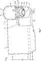
- an outer contour 24 of cover section 18 is preferably larger than an inner contour 26 (see Figure 7 ) of the at least one opening 16.
- outer contour 24 can also correspond to inner contour 26.
- an outer circumference 28 of cover section 18 can be larger than or equal to an inner circumference 30 of the at least one opening 16.
- an outer diameter 32 of round cover section 18 can be larger than or equal to an inner diameter 34 of round opening 16.
- cover section 18 can be configured to be planar. In order to cover an elongate opening 36 and/or to cover several adjacently disposed openings (not shown), cover section 18 can respectively be elongate and plate-shaped (see Figure 2 ). Housing cap 1 can optionally have longitudinal ribs 38 and/or transverse ribs 40 which reinforce cover section 18.
- Housing cap 1 can optionally have a sealing section 42 for sealing a gap 44 between housing cap 1 and the remainder of housing 2.
- Sealing section 42 is formed by a seal 46 with sealing lips 48 pointing inwardly and/or outwardly. Seal 46 is inserted, for example, in a circumferential groove 50 of cover section 18 as a separate sealing element 52 (see Figure 6 ) or is injected into groove 50 to form a two-component member (not shown) with housing cap 1.
- Housing 2 shown in Figures 3 and 4 comprises housing cap 1 and a housing part 54 with the at least one opening 16.
- housing part 54 has only one opening 16.
- housing part 54 can also have several openings (not shown).
- a housing cap 1 can be provided for all or at least several openings.
- a single housing cap 1 can also be provided for every opening.
- Housing cap 1 is configured such that it can be mounted onto the at least one opening 16. In the mounted state 56 of housing cap 1, the at least one stop 20 protrudes into the at least one opening 16 (see Figure 4 ).
- housing 2 comprises a power rail receptacle 58 and at least one screw head receptacle 60 that opens into power rail receptacle 58.
- housing 2 comprises only one power rail receptacle 58 and one screw head receptacle 60.
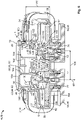
- Figure 6 shows by way of example a housing 2 with two power rail receptacles 58 and two screw head receptacles 60.
- yet more power rail receptacles 58 and/or screw head receptacles 60 can of course be provided.
- Figures 3 and 4 show electrical connection assembly 4 which, in addition to housing 2, comprises at least one power rail 62 received in power rail receptacle 58 of housing 2, at least one screw 8 and at least one contact element 64, for example, a battery terminal 66.
- Connection assembly 4 from Figures 3 and 4 comprises a power rail 62, a screw 8, and a contact element 64.
- connection assembly 4 can also comprise two power rails 62, two screws 8, and two contact elements 64.
- At least one screw 8 and one contact element 64 are preferably present for each power rail 62.
- the at least one power rail 62 is preferably made of metal (e.g. copper, aluminum) and/or a different electrically conductive material and comprises a passage hole 70 aligned with at least one screw head receptacle 60 in axial direction 68 of at least one screw 8.
- Passage hole 70 can be, for example, a circular passage hole, an oval passage hole, or an elongate hole.
- the at least one screw 8 has a thread 72 and a screw head 74, while the at least one contact element 64 has a mating-thread 76 configured to be complementary to thread 72 (see Figure 6 ).
- the at least one screw 8 and/or the at least one contact element 64 are preferably likewise made of metal (e.g. copper, aluminum) and/or a different electrically conductive material.
- mating-thread 76 is formed directly in the material of respective contact element 64, for example, by way of tapping, thread cutting, thread milling, thread pressing, thread forming or using another thread production method.
- the at least one contact element 64 can additionally comprise a separate component (not shown) that has mating-thread 76.
- the separate component can be a nut, for example, an insert nut inserted (not shown) on the other side or a nut overmolded with a touch guard made of electrically non-conductive material.
- the separate component can also be, for example, a threaded sleeve (not shown) that is pressed in, welded on, caulked and/or fastened in some other way.
- passage hole 76 is preferably aligned with at least one screw head receptacle 60 in axial direction 68. Respective contact surfaces 77 of the at least one power rail 62 and of the at least one contact element 64 can therefore contact one another and form an electrically conductive connection with a contact force 78 generated by the at least one screw 8.
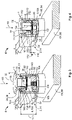
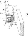
- the at least one screw 8 in particular its thread 72, is inserted into passage hole 70 of the at least one power rail 62 and mating-thread 76 of the at least one contact element 64. Consequently, the at least one screw 8 can be moved to a final assembly position 80 (see Figure 4 ) in which it is completely screwed into mating-thread 76. In other words, the at least one screw 8 can be screwed into mating-thread 76 from a position 82 in which it is screwed in incompletely (see Figure 3 ) to a position 84 in which it is screwed in completely (see Figure 4 ), whereby the at least screw head 74 moves in axial direction 68.
- screw head 74 is accessible from the outside via the at least one opening 16, in particular for a corresponding screwing tool (not shown), provided that housing cap 1 is not in mounted state 56.
- screw head 74 is there arranged in at least one screw head receptacle 60 of housing 2.
- the at least one stop 20 of housing cap 1 in mounted state 56 of housing cap 1 is aligned with at least one screw head receptacle 60 in axial direction 68.
- the at least one stop 20 is also configured to strike screw head 74 under these circumstances and to block the at least one opening 16 to be covered by cover section 18 (see Figure 3 ).
- the at least one stop 20 is configured to rest precisely on screw head 74 of the at least one screw 8 in position 84 in which it is screwed in completely and only then to enable at least one opening 16 to be covered by cover section 18 (see Figure 4 ).
- the at least one stop 20 of housing cap 1 in its mounted state 56 protrudes so far into the at least one opening 16 that it reaches exactly up to screw 8 disposed in final assembly position 80.
- housing cap 1 can comprise at least one spacing element 88 projecting from cover section 18, wherein the at least one stop 20 is arranged on this spacing element 88.
- stop 20 is located at an end 90 of spacing element 88 facing away from cover section 18.
- Stop 20 is preferably formed by an edge 92 of spacing element 88 pointing away from cover section 18.
- the at least one spacing element 88 preferably has a reinforcement zone 95 to increase its dimensional stability. It can be clearly seen from Figure 2 that the at least one spacing element 88 has a curved cross section 96, in particular in a plane 94 parallel to cover section 18, for creating reinforcement zone 95.
- the at least one spacing element 88 is configured as a semi-tubular shape, a hollow cylinder segment, or a hollow rotating body segment.
- the at least one spacing element 88 can be configured as a collar 98 which extends at least in sections around a receiving region 100 for receiving at least part of screw head 74. Collar 98 is preferably curved around receiving region 100.
- Edge 92 of spacing element 88 forming stop 20 is configured accordingly to have the shape of a segment of a circle or at least to be curved.
- the at least one spacing element 88 can have an angled cross-section (not shown) in plane 94 to create reinforcement zone 95.
- Reinforcement zone 95 can also be created by a bead (not shown) or rib (not shown) extending along spacing element 88.
- Housing cap 1 preferably comprises at least one stop 20 for each screw 8.
- the embodiments of housing cap 1 shown in Figures 1 and 2 each comprise two spacing elements 88, on each of which a stop 20 is arranged.
- two spacing elements 88 are each configured as collars 98 and each surround a receiving region 100 for one screw head 74 each.
- Spacing elements 88 can be configured to be symmetrical, in particular mirror-symmetrical to one another.
- spacing elements 88 are each configured as shovel- or spade-shaped projections 101 and together surround a receiving region 100 for a screw head 74.
- Two spacing elements 88 can also each have a convex, bulged, protruding or raised side surface 102 and a concave, indented or recessed side surface 104.
- concave side surfaces 104 of two spacing elements 88 face one another
- Figure 2 shows two spacing elements 88 with convex side surfaces 102 facing one another.
- Spacing elements 88 with concave side surfaces 104 facing one another are suitable, as already described, to jointly surround a receiving region 100. Respective stops 20 on these spacing elements 88 can therefore rest on one and the same screw head 74, resulting in improved support stability. In addition, there is a certain redundancy in the event that one spacing element 88 should break off.
- housing cap 1 with the two spacing elements 88 with convex side surfaces 102 facing one another comes to play primarily in electrical connection assemblies 4 with two screws 8, in particular two screws 8 extending in parallel (see Figure 6 ).
- spacing elements 88 With a predetermined distance 106 between screws 8 and under the condition that one spacing element 88 each is aligned with one respective screw head 74 in axial direction 68, spacing elements 88 can be arranged as close as possible to one another by facing their convex side surfaces 102 towards one another. Stops 20 are also correspondingly close. This in turn means that even a small difference in height between screw heads 74, such as occurs, for example, when at least one of two screws 8 is not in final assembly position 80, results in the greatest possible angle of inclination of housing cap 1. Consequently, the presence of an angle of inclination due to a screw 8 not being in final assembly position 80 can be more easily recognized using this embodiment.
- the at least one screw 8 can be a flange screw 108.
- the at least one screw 8 can have a flange 110 having a predetermined flange face thickness 112.
- the at least one screw can be configured as a hexagonal screw with a flange, a flat head screw, or a washer head screw.
- Passage hole 70 of the at least one power rail 62 can be surrounded by a bearing surface 114 (see Figure 3 ) for screw head 74, in particular for flange 108.
- a distance 116 measured in axial direction 68 between bearing surface 114 and the at least one stop 20 corresponds to flange face thickness 112 (see Figure 4 ).
- Screw head 74 can optionally comprise a touch guard 118 made of an electrically non-conductive material. Accordingly, the at least one stop 20 can strike or bear against touch guard 118.
- the material thickness of the touch guard is there included in flange face thickness 112.
- a distance 170 between an upper edge 168 of the at least one opening 16 and a bottom surface 164 of power rail receptacle 58 corresponds in general to the sum of material thickness 166 of the at least one power rail 62, flange face thickness 112, and length 86 from cover section 18 to the at least one stop 20 (see Figure 6 ).
- the at least one screw 8 can also be formed without a flange 110.
- the at least one stop 20 can then, for example, strike or bear against end 120 of screw head 74 facing away from thread 72.
- distance 116 when housing cap 1 is in mounted state 56, corresponds to a head height of screw head 74 measured in axial direction 68. Receiving region 100 for screw head 74 can then be omitted accordingly.
- housing cap 1 cannot be mounted on the at least one opening 16 of housing part 54, at least not completely, if the at least one stop 20 of housing cap 1 abuts against screw head 74 when screw 8 has been moved away from final assembly position 80. Under these circumstances, housing cap 1 can preferably also not be fastened to the remainder of housing 2. The presence of a screw 8 that is not in final assembly position 80 can also be recognized by way of at least one fastening element 22 described hereafter which is used to fasten housing cap 1 to the remainder of housing 2.
- the at least one fastening element 22 can be arranged on cover section 18 and/or on the at least one spacing element 88.
- the at least one fastening element 22 in Figures 1 to 4 is configured in particular as a latching hook 122 projecting from cover section 18.
- Latching hook 122 has a self-supporting arm 124 that extends at least in part along spacing elements 88 shown.
- latching hook 122 comprises a latching projection 126 which projects laterally from free end 128 of the self-supporting arm 124.
- Latching hook 122 optionally comprises an angular offset to spacing elements 88 with respect to receiving region 100.
- latching hook 122 is separated from spacing elements 88 by a respective flexural gap 130.
- Flexural gap 130 there preferably reduces the flexural rigidity of latching hook 122 so that an elastic deflection 132 perpendicular to axial direction 68 is facilitated.
- the at least one fastening element 22 can also be configured as a latching projection 126, in particular a latching tab 134 (see Figure 5 ), projecting laterally from spacing element 88.
- Latching projection 126 is preferably arranged on self-supporting arm 124 or on spacing element 88 pointing outwardly with respect to receiving region 100.
- latching projection 126 can also be configured to point inwardly.
- Elastic deflection 132 just mentioned can correspondingly take place inwardly or outwardly.
- housing 2 comprises a housing insert 136 which can be inserted into the at least one opening 16 and fastened to housing part 54.
- Housing insert 136 is fastened to housing part 54, for example, by way of a latching connection 138 (see Figure 7 ).
- the at least one screw head receptacle 60 in particular formed as a passage opening 140, is arranged in housing insert 136.
- One passage opening 140 each can there form a screw head receptacle 60.
- housing insert 136 can also be used as a separating element 142 between two power rails 62 and/or screws 8 (see Figure 6 ).
- Housing insert 136 is preferably made of electrically non-conductive material.
- Housing cap 1 and/or housing part 54 are preferably likewise made of electrically non-conductive material.
- Housing insert 136 is preferably configured to be insertable after the at least one screw 8 into the at least one opening 16. Housing insert 136 can therefore be used to hold at least one screw 8 in a captive manner already prior to housing cap 1 being mounted.
- housing insert 136 can comprise a latching collar 144 protruding inwardly into the at least one screw head receptacle 60.
- latching collar 144 is configured to extend around the at least one screw head receptacle 60.
- An inner diameter 146 (see Figure 7 ) of latching collar 144 is preferably smaller than an outer diameter 148 (see Figure 5 ) of screw head 74 arranged in screw head receptacle 60. Consequently, latching collar 144 can prevent screw 8 from accidentally dropping out or being removed.
- latching projections 126 of respective fastening elements 22 are configured such that they can be latched to latching collar 144. In this way, housing cap 1 can latch onto latching collar 144 so that latching collar 144 fulfills a dual function.
- Latching collar 144 can optionally form an insertion bevel 150 of the at least one opening 16 and/or of the at least one screw head receptacle 60.
- elastic deflection 132 can be caused in the context of housing cap 1 being mounted once latching projections 126 come up against insertion bevel 150. After latching collar 144 has been overcome, elastic deflection 132 is canceled out again by the relaxation of the material and latching projections 126 engage with latching collar 144 (see Figure 5 ). This engagement is preferably accompanied by a clicking sound which can be used as an audible indicator as described below.
- latching projections 126 can touch latching collar 144 at predetermined touch surfaces 152.
- these touch surfaces 152 are at same distance 154, measured in axial direction 68, from the at least one stop 20 when housing cap 1 is in mounted state 56.
- the absence of the audible indicator then necessarily indicates the presence of at least one screw 8 outside of final assembly position 80, especially since distance 154 between touch surface 152 on latching collar 144 and the at least one stop 20 depends on the position of screw head 74, whereas distance 154 between touch surface 152 on latching projection 126 and the at least one stop 20 is structurally defined.
- latching collar 144 can comprise a draw-off bevel 156.
- Draw-off bevel 156 is preferably arranged on the other side of insertion bevel 150 and meets insertion bevel 150 at inner diameter 146 of latching collar 144, preferably at an obtuse angle.
- insertion bevel 150 is arranged facing the at least one screw head receptacle 60.
- latching projections 126 can be formed to be beveled. In particular, when housing cap 1 is in mounted state 56, latching projections 126 can touch latching collar 144 at touch surfaces 152 which are inclined with respect to axial direction 68.
- Housing 2 can optionally comprise at least one point of engagement 162, e.g. a recess 158, for inserting a tool tip (not shown) between housing cap 1 and housing part 54.
- the at least one point of engagement 162 simplifies lifting off or levering open housing cap 1 with a tool, such as a screwdriver (not shown).
- at least one recess 158 is configured as a lateral depression 160 in cover section 18.
- One point of engagement 162 is preferably provided for each latching projection 126 of housing cap 1 with respect to housing cap 1 at a respective angular position. In other words, there is no angular offset between latching projection 126 and point of engagement 162.
- draw-off bevel 156 can also be omitted.
- latching projections 126 can touch latching collar 144 at touch surfaces which are perpendicular with respect to axial direction 68.
- latching projections 126 can optionally also engage behind latching collar 144 in the manner of a barb.
- latching collar 144 can also alternatively be arranged on the outside of housing part 54 according to an embodiment that is not shown.
- latching projections 126 can accordingly be configured to point inwardly and latch with latching collar 144 arranged on the outside.
- housing insert 136 can comprise a latching groove (not shown) and the at least one fastening element 22 of housing cap 1 can be configured such that it can be latched to the latching groove.
- at least one anchoring element 143 can be arranged on housing insert 136 and form a fastening assembly 145 with the at least one fastening element 22 of housing cap 1.
- a bayonet connection (not shown) can also be provided.
- the at least one fastening element 22 can be configured, for example, as a bayonet pin or bayonet button (not shown) which engages in a bayonet groove (not shown) in housing part 54 or housing insert 136.
- housing cap 1 and housing part 54 or housing insert 136, respectively can establish a frictionally engaged connection.
- Other types of positive-fit, positive substance-fit, and/or force-fit connections are of course also conceivable.
Landscapes
- Casings For Electric Apparatus (AREA)
- Insertion Pins And Rivets (AREA)
- Snaps, Bayonet Connections, Set Pins, And Snap Rings (AREA)
- Connections By Means Of Piercing Elements, Nuts, Or Screws (AREA)
- Details Of Connecting Devices For Male And Female Coupling (AREA)
- Processing Of Terminals (AREA)
- Cable Accessories (AREA)
Abstract
Description
- The present invention relates to a housing cap for a housing of an electrical connection assembly, for example, but not exclusively, an electrical connector with a screw connection, for example, for high-voltage applications in the automotive and energy technology fields. In addition, the present invention relates to a housing for an electrical connection assembly with such a housing cap. Furthermore, the present invention relates to an electrical connection assembly with a screw connection and such a housing.
- Screw connections are used in electrical connection assemblies in many applications in automotive and energy technology because they can be used to produce comparatively high contact forces and the contact resistances arising can consequently be kept low. With increasing system size and complexity, the number of screw connections increases and at the same time the risk increases that screws of individual screw connections are accidentally not screwed in or at least not screwed in completely during production or maintenance. A screw-by-screw individual examination with a tool or by hand creates additional expenditure in work and time. In addition, individual screw connections can then also again be accidentally overlooked.
- In addition, electrical connection assemblies often have to be surrounded by a housing for reasons of electrical safety, for which reason the screw connections are usually arranged within the housing, are accessible only via a housing opening, and are accordingly visible from the outside to a limited degree. In addition, the housing opening is often closed to protect against moisture and/or dirt so that screws that are not screwed in or at least not screwed in completely can remain undetected all the more easily.
- Accordingly, the present invention is based on the object of creating a possibility that allows for screw connections of an electrical connection assembly of the type mentioned at the outset to be verified without additional effort and to thereby reliably detect screws that are not screwed in or at least not screwed in completely.
- This object is satisfied by a housing cap for closing at least one opening of a housing part of an electrical connection assembly for receiving a screw head of a screw, wherein the housing cap comprises a cover section for covering the at least one opening, at least one stop for the screw head projecting away from the cover section, and at least one fastening element for affixing the housing cap onto the at least one opening.
- Due to the at least one stop, the present invention is advantageous for the reason that the housing cap can serve as a control gauge that the at least one screw is screwed in completely. In particular, the at least one stop can advantageously abut against the screw head and interfere with the at least one opening being covered by the cover section if the at least one screw is not screwed in or is at least not screwed in completely. In other words, a suitable design of the at least one stop can ensure that the latter rests precisely on the screw head when the at least one screw is screwed in completely. Only when the at least one stop rests precisely on the screw head is it possible to again cover the at least one opening with the cover section.
- The housing cap according to the invention can advantageously be used, for example, as a retrofit component for a housing part that has already been manufactured and installed, for example, as part of maintenance or repair work, and can replace a conventional housing cap that is already present. It can be ensured in particular with the housing cap according to the invention that the at least one screw has been screwed in completely after the maintenance or repair work. Since mounting the housing cap is part of the maintenance or repair work anyway, this does not create any additional work.
- Furthermore, a housing cap that is not mounted or not mounted correctly is easier to recognize from the outside than a screw that is not screwed in or is not screwed in completely, so that the detection reliability is also increased by the present invention.
- The invention can be further improved by the following embodiments which are advantageous by themselves and which may be combined with one another arbitrarily.
- According to one possible configuration, the housing cap can comprise at least one spacing element that projects in particular perpendicularly from the cover section and on which the at least one stop is arranged. Such a spacing element represents a measure that is easy to produce for creating the at least one stop.
- To increase the dimensional stability of the at least one spacing element, it can comprise a reinforcement zone. It can thus be achieved in particular that the at least one spacing element does not kink or break away, even with a comparatively small material thickness.
- The reinforcement zone can be produced, for example, by a rib and/or bead running along the spacing element. Alternatively or additionally, the at least one spacing element can have a curved or angled cross section to create the reinforcement zone. Preferably, the cross section is curved or angled in a plane parallel to the cover section. The at least one spacing element is configured, for example, as a collar which extends at least in sections around a receiving region for receiving at least part of the screw head.
- According to a further possible configuration, the housing cap can comprise at least two spacing elements, on each of which a stop is arranged. The at least two spacing elements can there be arranged to be mirror-symmetrical to one another. In particular, the at least two spacing elements increase the support stability of the housing cap. Both spacing elements can rest with their respective stops upon one and the same screw head. In applications with two screws, each spacing element can rest with its respective stop upon one screw head.
- The at least two spacing elements can have a convex side surface each and a concave side surface each. The convex side surfaces can be bulged, protruding, and/or raised side surfaces of the respective spacing elements. The concave side surfaces can be indented and/or recessed side surfaces of the respective spacing elements.
- In order to surround the aforementioned receiving region with the at least two spacing elements, the concave side surfaces can face each other. The respective stops on the spacing elements therefore create redundancy in the event that a spacing element should break off.
- Alternatively, the convex side surfaces can also be associated with one another. The advantage of this embodiment comes into play primarily in applications with two screws, in particular two screws extending in parallel. With a predetermined distance between the screws and under the condition that the spacing elements are aligned with the respective screw heads in the axial direction of the screws, the spacing elements can be arranged as close as possible to one another by facing each other with their convex side surfaces. The stops are accordingly also close, so that even a small difference in height between the screw heads creates the greatest possible angle of inclination of the housing cap. The angle of inclination again indicates that at least one of the two screws is not screwed in completely, which is consequently easier to detect with this configuration of the housing cap.
- In the case of a housing cap with more than two spacing elements, in particular with an even number of spacing elements, pairs of convex side surfaces and/or concave side surfaces can face one another. Convex side surfaces can also face concave side surfaces and vice versa, for example, for reasons of space.
- The housing cap can optionally have a sealing section for sealing a gap between the housing cap and the housing part. The sealing section is preferably formed by a seal with sealing lips pointing inwardly and/or outwardly. The seal is configured, for example, as a separate sealing element and seated in a circumferential groove in the cover section. Alternatively, the seal can also be injected into the groove and form a two-component member with the housing cap.
- The aforementioned object can also be satisfied by a housing for an electrical connection assembly, where the housing comprises at least one housing cap, a housing part with at least one opening, a power rail receptacle for receiving at least one electrical power rail, and at least one screw head receptacle for receiving a screw head of a screw that opens into the power rail receptacle, and wherein the at least one housing cap is a housing cap according to one of the above embodiments.
- The housing according to the invention benefits from the advantages of the housing cap already explained. In particular, the housing can be installed as part of the electrical connection assembly and the housing cap can be used to ensure that the at least one screw is screwed in completely. The housing cap is there configured such that it can be mounted onto the at least one opening. When the housing cap is mounted, the at least one stop preferably protrudes into the at least one opening and is aligned with the at least one screw head receptacle in the axial direction of the screw.
- According to a further possible configuration, the housing can comprise a housing insert which is configured to be able to be inserted into the at least one opening and fastened to the housing part and which forms the at least one screw head receptacle. As shall be explained in more detail below, the at least one screw can advantageously be captively held with the housing insert.
- An anchoring element can optionally be arranged at the housing insert and form a fastening assembly with the at least one fastening element of the housing cap. In particular, the anchoring element can be a mating part configured to be complementary to the at least one fastening element of the housing cap. The at least one fastening element can be arranged at the cover section and/or at the at least one spacing element. The housing cap can therefore be affixed in a simple manner on the at least one opening.
- For example, the anchoring element is configured as a latching collar that projects inwardly into the at least one screw head receptacle and that is optionally formed to be circumferential. The at least one fastening element of the housing cap correspondingly has an outwardly pointing latching projection which can be latched to the latching collar.
- The embodiment with a latching collar is advantageous because it fulfills a dual function. Firstly, the housing cap can latch thereonto. Secondly, as already briefly mentioned, the at least one screw can be held captively in the at least one screw head receptacle with the latching collar. For this purpose, an inner diameter of the latching collar is preferably smaller than an outer diameter of the screw head arranged in the at least one screw head receptacle and the housing insert is preferably installed in the housing part only after the at least one screw. The latching collar can then prevent the at least one screw from accidentally dropping out or being removed already prior to the housing cap being mounted.
- In order to simplify mounting the housing cap, the latching collar can form an insertion bevel of the at least one opening. Additionally or alternatively, the latching collar can comprise a draw-off bevel which makes it easier to remove the housing cap.
- The housing can optionally comprise at least one point of engagement for inserting a tool tip between the housing cap and the housing part. This additionally makes it easier to remove the housing cap.
- As an alternative to the latching collar, the housing insert can also comprise a latching groove to which the latching projection of the at least one fastening element latches. Alternatively, the latching collar and/or the latching groove can also be arranged on the outside of the housing part, where the latching projection of the at least one fastening element correspondingly points inwardly.
- According to a further possible configuration, an outer contour of the cover section of the housing cap can be larger than an inner contour of the at least one opening of the housing part. This ensures that the cover section covers the at least one opening completely.
- Alternatively, the outer contour of the cover section can also be of the same size as the inner contour of the at least one opening. This not only ensures that the cover section covers the at least one opening exactly, but also that the at least one screw is actually present in the housing. If the screw was forgotten from the outset, the housing cap sinks into the at least one opening and thereby inevitably signals that the screw is missing.
- The aforementioned object can also be satisfied by an electrical connection assembly, wherein the connection assembly comprises a housing according to one of the above configurations, at least one power rail that can be received in the power rail receptacle of the housing and has a passage hole, at least one screw that can be inserted into the passage hole and has a thread and a screw head, as well as at least one contact element having a mating-thread that is configured to be complementary to the thread of the at least one screw.
- The passage hole can be, for example, a circular passage hole, an oval passage hole, or an elongate hole. The mating-thread can be formed directly in the material of the at least one contact element, for example, by tapping, thread cutting, thread milling, thread pressing, thread forming or another thread production method. Alternatively, the at least one contact element can additionally comprise a separate component that has the mating-thread. In particular, the separate component can be a nut, for example, an insert nut inserted on the other side or a nut overmolded with a touch guard made of electrically non-conductive material. Furthermore, the separate component can also be, for example, a threaded sleeve that is pressed in, welded on, caulked and/or fastened in some other way.
- The connection assembly utilizes the advantages of the invention that have already been described and due to the housing cap of the housing possesses an integrated control mechanism that ensures that the at least one screw is screwed in completely. As a result, the connection assembly according to the invention is less susceptible to incorrect assembly, without additional work or time being required for this. In particular, the electrical and thermal safety of the connection assembly according to the invention increases because unwanted excessive heating during operation is prevented. Because such excessive heating could be caused due to an increase in contact resistance by an overlooked screw that is not screwed in completely and the resulting lack of contact force.
- The screw head of the at least one screw is preferably arranged in the at least one screw head receptacle of the housing. Furthermore, the passage hole is preferably aligned in the axial direction with the at least one screw head receptacle. The at least one screw can therefore be transferred to a final assembly position in which it is completely screwed into the mating-thread. When the screw is moved out of the final assembly position, the at least one stop of the housing cap abuts against the screw head so that the housing cap cannot be mounted, or at least not completely, onto the at least one opening of the housing part. In other words, when the housing cap is mounted, the at least one stop extends up to the at least one screw in the final assembly position.
- According to one possible embodiment of the connection assembly, the at least one screw can have a flange with a predetermined flange face thickness. The distance between an upper edge of the at least one opening and a bottom surface of the power rail receptacle corresponds preferably to the sum of the material thickness of the at least one power rail, the flange face thickness, and the length from the cover section to the at least one stop. When the housing cap is mounted, the distance between the at least one stop and the bottom surface then corresponds to the sum of the material thickness and the flange face thickness. In other words, the at least one stop of the housing cap extends up to the flange when the at least one screw is screwed in completely and is in the final assembly position. Advantageously, the housing cap affixed on the at least one opening can then prevent the at least one screw from being unscrewed from the final assembly position due to vibration.
- In order to extend the usability of the housing to applications with several screws, the housing, in particular the housing insert, can comprise at least two screw head receptacles. The connection assembly can accordingly comprise at least two screws. Depending on the particular application, the housing can of course also comprise yet more screw head receptacles and the connection assembly can have yet more screws. Correspondingly, the housing cap can comprise at least one stop for each screw head receptacle of the housing or for each screw of the connection assembly, respectively. Advantageously, several screws can be inspected at the same time with the housing cap. This represents an aid for assembly, repair, and/or maintenance work.
- In the case of a housing part with several openings, a single housing cap can be provided for all openings. Alternatively, an individual housing cap can also be provided for every opening. Furthermore, as an alternative, several housing caps can also be respectively provided for several different openings.
- The invention shall be explained in more detail hereafter by way of example with reference to the drawings. The feature combinations illustrated in the embodiments shown by way of example can be supplemented by further features in accordance with the above statements in correspondence with the properties of the invention required for a specific application. Individual features can also be omitted in accordance with the above statements from the embodiments described if the effect of these features is of no relevance for a specific application. The same reference numerals in the drawings are always used for elements having the same function and/or the same structure,
where: - Fig. 1
- shows a schematic perspective illustration of a housing cap according to a first exemplary embodiment;
- Fig. 2
- shows a schematic perspective illustration of a housing cap according to a second exemplary embodiment;
- Fig. 3
- shows a schematic perspective partial sectional illustration of an electrical connection assembly with the housing cap from
Figure 1 ; - Fig. 4
- shows a further schematic perspective illustration of the electrical connection assembly from
Figure 3 ; - Fig. 5
- shows a schematic perspective partial sectional illustration of an electrical connection assembly with a housing cap according to a third exemplary embodiment;
- Fig. 6
- shows a schematic perspective sectional illustration of an electrical connection assembly with the housing cap from
Figure 2 ; and - Fig. 7
- shows a schematic perspective partial sectional illustration of an electrical connection assembly according to a further exemplary embodiment.
- The schematic structure of
housing cap 1 according to the invention shall be described hereafter according to exemplary embodiments with reference toFigures 1 to 6 . Furthermore, the schematic structure of ahousing 2 according to the invention and anelectrical connection assembly 4 according to the invention shall be explained with reference toFigures 3 to 7 . -
Housing 2 protectselectrical connection assembly 4 from unwanted contact, dirt, and/or moisture, wherein at least onescrew 8 ofelectrical connection assembly 4 is arranged ininterior 6 ofhousing 2. For example,electrical connection assembly 4 can be an electrical connector 10 with ascrew connection 12 andhousing 2 can be a corresponding connector housing 14.Housing cap 1 serves to close at least oneopening 16 ofhousing 2 through which the at least onescrew 8 is accessible, and at the same time acts as a control gauge for verifying that the at least onescrew 8 is screwed in completely. This shall be explained in more detail hereafter. - As can be seen from
Figure 1 ,housing cap 1 comprises acover section 18, at least onestop 20 which projects preferably perpendicularly fromcover section 18, and at least one fastening element 22. In the embodiments shown,housing cap 1 comprises twostops 20 and two fastening elements 22. Depending on the application, yet more stops 20 and/or fastening elements 22 can of course also be provided. The number ofstops 20 and fastening elements 22 can differ from one another. -
Cover section 18 is provided to cover the at least oneopening 16. For this purpose, anouter contour 24 ofcover section 18 is preferably larger than an inner contour 26 (seeFigure 7 ) of the at least oneopening 16. Alternatively,outer contour 24 can also correspond toinner contour 26. - In other words, an outer circumference 28 of
cover section 18 can be larger than or equal to an inner circumference 30 of the at least oneopening 16. For example, in the case of around cover section 18 for covering around opening 16, anouter diameter 32 ofround cover section 18 can be larger than or equal to aninner diameter 34 ofround opening 16. - As shown in
Figure 1 ,cover section 18 can be configured to be planar. In order to cover an elongate opening 36 and/or to cover several adjacently disposed openings (not shown),cover section 18 can respectively be elongate and plate-shaped (seeFigure 2 ).Housing cap 1 can optionally havelongitudinal ribs 38 and/ortransverse ribs 40 which reinforcecover section 18. -
Housing cap 1 can optionally have a sealing section 42 for sealing agap 44 betweenhousing cap 1 and the remainder ofhousing 2. Sealing section 42 is formed by a seal 46 with sealinglips 48 pointing inwardly and/or outwardly. Seal 46 is inserted, for example, in acircumferential groove 50 ofcover section 18 as a separate sealing element 52 (seeFigure 6 ) or is injected intogroove 50 to form a two-component member (not shown) withhousing cap 1. -
Housing 2 shown inFigures 3 and 4 compriseshousing cap 1 and ahousing part 54 with the at least oneopening 16. In the embodiments shown by way of example,housing part 54 has only oneopening 16. Of course,housing part 54 can also have several openings (not shown). In this case, ahousing cap 1 can be provided for all or at least several openings. Alternatively, asingle housing cap 1 can also be provided for every opening. -
Housing cap 1 is configured such that it can be mounted onto the at least oneopening 16. In the mountedstate 56 ofhousing cap 1, the at least onestop 20 protrudes into the at least one opening 16 (seeFigure 4 ). - As can also be seen from the sectional illustrations shown,
housing 2 comprises apower rail receptacle 58 and at least onescrew head receptacle 60 that opens intopower rail receptacle 58. In the exemplary embodiments shown inFigures 3 to 5 ,housing 2 comprises only onepower rail receptacle 58 and onescrew head receptacle 60.Figure 6 shows by way of example ahousing 2 with twopower rail receptacles 58 and twoscrew head receptacles 60. Depending on the application, yet morepower rail receptacles 58 and/or screwhead receptacles 60 can of course be provided. -
Figures 3 and 4 showelectrical connection assembly 4 which, in addition tohousing 2, comprises at least onepower rail 62 received inpower rail receptacle 58 ofhousing 2, at least onescrew 8 and at least one contact element 64, for example, a battery terminal 66.Connection assembly 4 fromFigures 3 and 4 comprises apower rail 62, ascrew 8, and a contact element 64. As shown inFigure 6 ,connection assembly 4 can also comprise twopower rails 62, twoscrews 8, and two contact elements 64. Depending on the application, even more power rails 62,screws 8 and/or contact elements 64 can of course be provided. At least onescrew 8 and one contact element 64 are preferably present for eachpower rail 62. - The at least one
power rail 62 is preferably made of metal (e.g. copper, aluminum) and/or a different electrically conductive material and comprises apassage hole 70 aligned with at least onescrew head receptacle 60 inaxial direction 68 of at least onescrew 8.Passage hole 70 can be, for example, a circular passage hole, an oval passage hole, or an elongate hole. - The at least one
screw 8 has athread 72 and ascrew head 74, while the at least one contact element 64 has a mating-thread 76 configured to be complementary to thread 72 (seeFigure 6 ). The at least onescrew 8 and/or the at least one contact element 64 are preferably likewise made of metal (e.g. copper, aluminum) and/or a different electrically conductive material. - In the exemplary embodiment from
Figure 6 , mating-thread 76 is formed directly in the material of respective contact element 64, for example, by way of tapping, thread cutting, thread milling, thread pressing, thread forming or using another thread production method. Alternatively, the at least one contact element 64 can additionally comprise a separate component (not shown) that has mating-thread 76. In particular, the separate component can be a nut, for example, an insert nut inserted (not shown) on the other side or a nut overmolded with a touch guard made of electrically non-conductive material. Furthermore, the separate component can also be, for example, a threaded sleeve (not shown) that is pressed in, welded on, caulked and/or fastened in some other way. - Furthermore,
passage hole 76 is preferably aligned with at least onescrew head receptacle 60 inaxial direction 68. Respective contact surfaces 77 of the at least onepower rail 62 and of the at least one contact element 64 can therefore contact one another and form an electrically conductive connection with acontact force 78 generated by the at least onescrew 8. - For this purpose, the at least one
screw 8, in particular itsthread 72, is inserted intopassage hole 70 of the at least onepower rail 62 and mating-thread 76 of the at least one contact element 64. Consequently, the at least onescrew 8 can be moved to a final assembly position 80 (seeFigure 4 ) in which it is completely screwed into mating-thread 76. In other words, the at least onescrew 8 can be screwed into mating-thread 76 from aposition 82 in which it is screwed in incompletely (seeFigure 3 ) to a position 84 in which it is screwed in completely (seeFigure 4 ), whereby the atleast screw head 74 moves inaxial direction 68. To move the at least onescrew 8 to its final assembly position 80,screw head 74 is accessible from the outside via the at least oneopening 16, in particular for a corresponding screwing tool (not shown), provided thathousing cap 1 is not in mountedstate 56. In particular,screw head 74 is there arranged in at least onescrew head receptacle 60 ofhousing 2. - The at least one
stop 20 ofhousing cap 1 in mountedstate 56 ofhousing cap 1 is aligned with at least onescrew head receptacle 60 inaxial direction 68. In order to preventhousing cap 1 from being mounted on the at least oneopening 16 while the at least onescrew 8 is still inposition 82 in which it is screwed in incompletely or at least not in final assembly position 80, the at least onestop 20 is also configured to strikescrew head 74 under these circumstances and to block the at least oneopening 16 to be covered by cover section 18 (seeFigure 3 ). In other words, the at least onestop 20 is configured to rest precisely onscrew head 74 of the at least onescrew 8 in position 84 in which it is screwed in completely and only then to enable at least oneopening 16 to be covered by cover section 18 (seeFigure 4 ). For this purpose, the at least onestop 20 ofhousing cap 1 in its mountedstate 56 protrudes so far into the at least oneopening 16 that it reaches exactly up toscrew 8 disposed in final assembly position 80. The at least onestop 20 there reaches the at least onescrew 8 if alength 86 measured perpendicular to cover section 18 (seeFigure 1 ) extends betweencover section 18 and stop 20 up toscrew 8, in particular to itsscrew head 74. - As can be seen from
Figures 1 and 2 ,housing cap 1 can comprise at least one spacing element 88 projecting fromcover section 18, wherein the at least onestop 20 is arranged on this spacing element 88. In particular, stop 20 is located at anend 90 of spacing element 88 facing away fromcover section 18.Stop 20 is preferably formed by anedge 92 of spacing element 88 pointing away fromcover section 18. - The at least one spacing element 88 preferably has a
reinforcement zone 95 to increase its dimensional stability. It can be clearly seen fromFigure 2 that the at least one spacing element 88 has acurved cross section 96, in particular in aplane 94 parallel to coversection 18, for creatingreinforcement zone 95. For example, the at least one spacing element 88 is configured as a semi-tubular shape, a hollow cylinder segment, or a hollow rotating body segment. In particular, the at least one spacing element 88 can be configured as a collar 98 which extends at least in sections around a receivingregion 100 for receiving at least part ofscrew head 74. Collar 98 is preferably curved around receivingregion 100.Edge 92 of spacing element 88 formingstop 20 is configured accordingly to have the shape of a segment of a circle or at least to be curved. - Alternatively, the at least one spacing element 88 can have an angled cross-section (not shown) in
plane 94 to createreinforcement zone 95.Reinforcement zone 95 can also be created by a bead (not shown) or rib (not shown) extending along spacing element 88. -
Housing cap 1 preferably comprises at least onestop 20 for eachscrew 8. The embodiments ofhousing cap 1 shown inFigures 1 and 2 each comprise two spacing elements 88, on each of which astop 20 is arranged. InFigure 2 , two spacing elements 88 are each configured as collars 98 and each surround a receivingregion 100 for onescrew head 74 each. Spacing elements 88 can be configured to be symmetrical, in particular mirror-symmetrical to one another. In the embodiment ofFigure 1 , spacing elements 88 are each configured as shovel- or spade-shaped projections 101 and together surround a receivingregion 100 for ascrew head 74. - Two spacing elements 88 can also each have a convex, bulged, protruding or raised
side surface 102 and a concave, indented or recessedside surface 104. In the case ofhousing cap 1 shown inFigure 1 , concave side surfaces 104 of two spacing elements 88 face one another, whereasFigure 2 shows two spacing elements 88 with convex side surfaces 102 facing one another. - Spacing elements 88 with concave side surfaces 104 facing one another are suitable, as already described, to jointly surround a receiving
region 100. Respective stops 20 on these spacing elements 88 can therefore rest on one and thesame screw head 74, resulting in improved support stability. In addition, there is a certain redundancy in the event that one spacing element 88 should break off. - The advantage of the embodiment of
housing cap 1 with the two spacing elements 88 with convex side surfaces 102 facing one another comes to play primarily inelectrical connection assemblies 4 with twoscrews 8, in particular twoscrews 8 extending in parallel (seeFigure 6 ). With apredetermined distance 106 betweenscrews 8 and under the condition that one spacing element 88 each is aligned with onerespective screw head 74 inaxial direction 68, spacing elements 88 can be arranged as close as possible to one another by facing their convex side surfaces 102 towards one another.Stops 20 are also correspondingly close. This in turn means that even a small difference in height between screw heads 74, such as occurs, for example, when at least one of twoscrews 8 is not in final assembly position 80, results in the greatest possible angle of inclination ofhousing cap 1. Consequently, the presence of an angle of inclination due to ascrew 8 not being in final assembly position 80 can be more easily recognized using this embodiment. - As can be seen in
Figures 3 to 6 , the at least onescrew 8 can be a flange screw 108. In other words, the at least onescrew 8 can have aflange 110 having a predeterminedflange face thickness 112. For example, the at least one screw can be configured as a hexagonal screw with a flange, a flat head screw, or a washer head screw.Passage hole 70 of the at least onepower rail 62 can be surrounded by a bearing surface 114 (seeFigure 3 ) forscrew head 74, in particular for flange 108. Inmounted state 56 ofhousing cap 1, adistance 116 measured inaxial direction 68 between bearingsurface 114 and the at least onestop 20 corresponds to flange face thickness 112 (seeFigure 4 ).Screw head 74 can optionally comprise atouch guard 118 made of an electrically non-conductive material. Accordingly, the at least onestop 20 can strike or bear againsttouch guard 118. The material thickness of the touch guard is there included inflange face thickness 112. - A
distance 170 between anupper edge 168 of the at least oneopening 16 and abottom surface 164 ofpower rail receptacle 58 corresponds in general to the sum ofmaterial thickness 166 of the at least onepower rail 62,flange face thickness 112, andlength 86 fromcover section 18 to the at least one stop 20 (seeFigure 6 ). - Alternatively, the at least one
screw 8 can also be formed without aflange 110. The at least onestop 20 can then, for example, strike or bear againstend 120 ofscrew head 74 facing away fromthread 72. In this case,distance 116, whenhousing cap 1 is in mountedstate 56, corresponds to a head height ofscrew head 74 measured inaxial direction 68. Receivingregion 100 forscrew head 74 can then be omitted accordingly. - Particularly in the case of
screws 8 whosescrew head 74 inscrew head receptacle 60 completely obscures the view onto bearingsurface 114, the screwing depth ofscrew 8 is only difficult to estimate, so that slight deviations ofscrew 8 from its final assembly position 80 are difficult to detect from the outside. This is evident fromFigure 7 , where a diagonal top view into ascrew head receptacle 60 is shown.Housing cap 1 according to the invention provides a remedy there. - As described so far,
housing cap 1 cannot be mounted on the at least oneopening 16 ofhousing part 54, at least not completely, if the at least onestop 20 ofhousing cap 1 abuts againstscrew head 74 whenscrew 8 has been moved away from final assembly position 80. Under these circumstances,housing cap 1 can preferably also not be fastened to the remainder ofhousing 2. The presence of ascrew 8 that is not in final assembly position 80 can also be recognized by way of at least one fastening element 22 described hereafter which is used to fastenhousing cap 1 to the remainder ofhousing 2. - The at least one fastening element 22 can be arranged on
cover section 18 and/or on the at least one spacing element 88. The at least one fastening element 22 inFigures 1 to 4 is configured in particular as a latching hook 122 projecting fromcover section 18. Latching hook 122 has a self-supportingarm 124 that extends at least in part along spacing elements 88 shown. Furthermore, latching hook 122 comprises a latchingprojection 126 which projects laterally fromfree end 128 of the self-supportingarm 124. - Latching hook 122 optionally comprises an angular offset to spacing elements 88 with respect to receiving
region 100. In particular, latching hook 122 is separated from spacing elements 88 by a respectiveflexural gap 130.Flexural gap 130 there preferably reduces the flexural rigidity of latching hook 122 so that anelastic deflection 132 perpendicular toaxial direction 68 is facilitated. Alternatively, the at least one fastening element 22 can also be configured as a latchingprojection 126, in particular a latching tab 134 (seeFigure 5 ), projecting laterally from spacing element 88. - Latching
projection 126 is preferably arranged on self-supportingarm 124 or on spacing element 88 pointing outwardly with respect to receivingregion 100. Alternatively, latchingprojection 126 can also be configured to point inwardly.Elastic deflection 132 just mentioned can correspondingly take place inwardly or outwardly. - As can be seen from
Figures 3 to 7 ,housing 2 comprises ahousing insert 136 which can be inserted into the at least oneopening 16 and fastened tohousing part 54.Housing insert 136 is fastened tohousing part 54, for example, by way of a latching connection 138 (seeFigure 7 ). Furthermore, the at least onescrew head receptacle 60, in particular formed as a passage opening 140, is arranged inhousing insert 136. One passage opening 140 each can there form ascrew head receptacle 60. - In embodiments of
connection assembly 4 with twopower rails 62,housing insert 136 can also be used as a separatingelement 142 between twopower rails 62 and/or screws 8 (seeFigure 6 ).Housing insert 136 is preferably made of electrically non-conductive material.Housing cap 1 and/orhousing part 54 are preferably likewise made of electrically non-conductive material. -
Housing insert 136 is preferably configured to be insertable after the at least onescrew 8 into the at least oneopening 16.Housing insert 136 can therefore be used to hold at least onescrew 8 in a captive manner already prior tohousing cap 1 being mounted. For this purpose,housing insert 136 can comprise alatching collar 144 protruding inwardly into the at least onescrew head receptacle 60. Optionally, latchingcollar 144 is configured to extend around the at least onescrew head receptacle 60. An inner diameter 146 (seeFigure 7 ) of latchingcollar 144 is preferably smaller than an outer diameter 148 (seeFigure 5 ) ofscrew head 74 arranged inscrew head receptacle 60. Consequently, latchingcollar 144 can preventscrew 8 from accidentally dropping out or being removed. - In the embodiments shown, latching
projections 126 of respective fastening elements 22 are configured such that they can be latched to latchingcollar 144. In this way,housing cap 1 can latch onto latchingcollar 144 so that latchingcollar 144 fulfills a dual function. - Latching
collar 144 can optionally form aninsertion bevel 150 of the at least oneopening 16 and/or of the at least onescrew head receptacle 60. In particular, above-mentionedelastic deflection 132 can be caused in the context ofhousing cap 1 being mounted once latchingprojections 126 come up againstinsertion bevel 150. After latchingcollar 144 has been overcome,elastic deflection 132 is canceled out again by the relaxation of the material and latchingprojections 126 engage with latching collar 144 (seeFigure 5 ). This engagement is preferably accompanied by a clicking sound which can be used as an audible indicator as described below. - In
mounted state 56 ofhousing cap 1, latchingprojections 126 can touch latchingcollar 144 at predetermined touch surfaces 152. In order to synchronize the occurrence of the audible indicator with the at least onestop 20 resting onscrew head 74, thesetouch surfaces 152 are atsame distance 154, measured inaxial direction 68, from the at least onestop 20 whenhousing cap 1 is in mountedstate 56. The absence of the audible indicator then necessarily indicates the presence of at least onescrew 8 outside of final assembly position 80, especially sincedistance 154 betweentouch surface 152 on latchingcollar 144 and the at least onestop 20 depends on the position ofscrew head 74, whereasdistance 154 betweentouch surface 152 on latchingprojection 126 and the at least onestop 20 is structurally defined. - In order to make it easier to remove
housing cap 1, latchingcollar 144 can comprise a draw-off bevel 156. Draw-off bevel 156 is preferably arranged on the other side ofinsertion bevel 150 and meetsinsertion bevel 150 atinner diameter 146 of latchingcollar 144, preferably at an obtuse angle. Furthermore,insertion bevel 150 is arranged facing the at least onescrew head receptacle 60. In addition to or as an alternative toinsertion bevel 150 and/or to draw-off bevel 156, latchingprojections 126 can be formed to be beveled. In particular, whenhousing cap 1 is in mountedstate 56, latchingprojections 126 can touch latchingcollar 144 attouch surfaces 152 which are inclined with respect toaxial direction 68. -
Housing 2 can optionally comprise at least one point of engagement 162, e.g. a recess 158, for inserting a tool tip (not shown) betweenhousing cap 1 andhousing part 54. The at least one point of engagement 162 simplifies lifting off or leveringopen housing cap 1 with a tool, such as a screwdriver (not shown). For example, at least one recess 158 is configured as a lateral depression 160 incover section 18. One point of engagement 162 is preferably provided for each latchingprojection 126 ofhousing cap 1 with respect tohousing cap 1 at a respective angular position. In other words, there is no angular offset between latchingprojection 126 and point of engagement 162. - In applications in which
housing cap 1 is not intended to be removable but instead is intended, for example, to serve as protection against tampering, draw-off bevel 156 can also be omitted. In particular, whenhousing cap 1 is in mountedstate 56, latchingprojections 126 can touch latchingcollar 144 at touch surfaces which are perpendicular with respect toaxial direction 68. In the mountedstate 56 ofhousing cap 1, latchingprojections 126 can optionally also engage behind latchingcollar 144 in the manner of a barb. - If there is no need for the at least one
screw 8 to be held in a captive manner, latchingcollar 144 can also alternatively be arranged on the outside ofhousing part 54 according to an embodiment that is not shown. In this embodiment, latchingprojections 126 can accordingly be configured to point inwardly and latch with latchingcollar 144 arranged on the outside. - In addition to or instead of latching
collar 144,housing insert 136 can comprise a latching groove (not shown) and the at least one fastening element 22 ofhousing cap 1 can be configured such that it can be latched to the latching groove. In general, at least one anchoring element 143 can be arranged onhousing insert 136 and form afastening assembly 145 with the at least one fastening element 22 ofhousing cap 1. - As an alternative to latching
assembly 145 described so far, a bayonet connection (not shown) can also be provided. In this case, the at least one fastening element 22 can be configured, for example, as a bayonet pin or bayonet button (not shown) which engages in a bayonet groove (not shown) inhousing part 54 orhousing insert 136. Additionally or alternatively,housing cap 1 andhousing part 54 orhousing insert 136, respectively, can establish a frictionally engaged connection. Other types of positive-fit, positive substance-fit, and/or force-fit connections are of course also conceivable. -
- 1
- housing cap
- 2
- housing
- 4
- connection assembly
- 6
- interior
- 8
- screw
- 10
- connector
- 12
- screw connection
- 14
- connector housing
- 16
- opening
- 18
- cover section
- 20
- stop
- 22
- fastening element
- 24
- outer contour
- 26
- inner contour
- 28
- circumference
- 30
- circumference
- 32
- outer diameter
- 34
- inner diameter
- 36
- opening
- 38
- longitudinal rib
- 40
- transverse rib
- 42
- sealing section
- 44
- gap
- 46
- seal
- 48
- sealing lip
- 50
- groove
- 52
- sealing element
- 54
- housing part
- 56
- state
- 58
- power rail receptacle
- 60
- screw head receptacle
- 62
- power rail
- 64
- contact element
- 66
- battery terminal
- 68
- direction
- 70
- passage hole
- 72
- thread
- 74
- screw head
- 76
- mating-thread
- 77
- contact surface
- 78
- contact force
- 80
- final assembly position
- 82
- position
- 84
- position
- 86
- length
- 88
- spacing element
- 90
- end
- 92
- edge
- 94
- plane
- 95
- reinforcement zone
- 96
- cross section
- 98
- collar
- 100
- receiving region
- 101
- projection
- 102
- side surface
- 104
- side surface
- 106
- distance
- 108
- flange screw
- 110
- flange
- 112
- flange face thickness
- 114
- bearing surface
- 116
- distance
- 118
- touch guard
- 120
- end
- 122
- latching hook
- 124
- arm
- 126
- latching projection
- 128
- end
- 130
- flexural gap
- 132
- deflection
- 134
- latching tab
- 136
- housing insert
- 138
- latching connection
- 140
- passage opening
- 142
- separating element
- 143
- anchoring element
- 144
- latching collar
- 145
- fastening assembly
- 146
- inner diameter
- 148
- outer diameter
- 150
- insertion bevel
- 152
- contact surface
- 154
- distance
- 156
- draw-off bevel
- 158
- recess
- 160
- depression
- 162
- point of engagement
- 164
- bottom surface
- 166
- material thickness
- 168
- upper edge
- 170
- distance
Claims (15)
- Housing cap (1) for closing at least one opening (16) of a housing part (54) of an electrical connection assembly (4) for receiving a screw head (74) of a screw (8), wherein said housing cap (1) comprises a cover section (18) for covering said at least one opening (16), at least one stop (20) for said screw head (74) projecting away from said cover section (18), and at least one fastening element (22) for affixing said housing cap (1) onto said at least one opening (16).
- Housing cap (1) according to claim 1, wherein said housing cap (1) comprises at least one spacing element (88) which projects from said cover section (18) and on which said at least one stop (20) is arranged.
- Housing cap (1) according to claim 2, wherein said at least one spacing element (88) comprises a reinforcement zone (95) to increase its dimensional stability.
- Housing cap (1) according to claim 2 or 3, wherein said housing cap (1) comprises at least two spacing elements (88), on each of which one stop (20) is arranged.
- Housing cap (1) according to claim 4, wherein said at least two spacing elements (88) each have a convex side surface (102) and each a concave side surface (104), and where said convex side surfaces (102) or said concave side surfaces (104) are facing each other.
- Housing (2) for an electrical connection assembly (4), comprising- at least one housing cap (1),- a housing part (54) with at least one opening (16),- a power rail receptacle (58) for receiving at least one electrical power rail (62), and- at least one screw head receptacle (60) that opens into said power rail receptacle (58) for receiving a screw head (74) of a screw (8), wherein said at least one housing cap (1) is a housing cap (1) according to one of the claims 1 to 5.
- Housing (2) according to claim 6, wherein said housing (2) comprises a housing insert (136) which is configured to be able to be inserted into said at least one opening (16) and fastened to said housing part (54) and which forms said at least one screw head receptacle (60).
- Housing (2) according to claim 7, wherein an anchoring element (143) is arranged on said housing insert (136) and forms a fastening assembly (145) with said at least one fastening element (22) of said housing cap (1).
- Housing (2) according to claim 8, wherein said anchoring element (143) is configured as a latching collar (144) protruding inwardly into said at least one screw head receptacle (60).
- Housing (2) according to one of the claims 6 to 9, wherein said housing (2) comprises at least one point of engagement (162) for inserting a tool tip between said housing cap (1) and said housing part (54).
- Housing (2) according to one of the claims 6 to 10, wherein an outer contour (24) of said cover section (18) of said housing cap (1) is larger than or equal to an inner contour (26) of said at least one opening (16) of said housing part (54).
- Housing (2) according to one of the claims 6 to 11, wherein said housing (2) comprises at least two screw head receptacles (60) and said housing cap (1) comprises at least one stop (20) for each screw head receptacle (60).
- Electrical connection assembly (4) comprising- a housing (2) according to one of the claims 6 to 12,- at least one power rail (62) which can be received in said power rail receptacle (58) of said housing (2) and has a passage hole (70),- at least one screw (8) which can be inserted into said passage hole (70) and has a thread (72) and a screw head (74), and- at least one contact element (64) with a mating-thread (76) that is configured to be complementary to said thread (72) of said at least one screw (8).
- Connection assembly (4) according to claim 13, wherein said at least one screw (8) comprises a flange (110) with a predetermined flange face thickness (112), wherein the distance (170) between an upper edge (168) of said at least one opening (16) and a bottom surface (164) of said power rail receptacle (58) corresponds to the sum of the material thickness (166) of said at least one power rail (62), said flange face thickness (112), and the length (86) from said cover section (18) to said at least one stop (20).
- Connection assembly (4) according to claim 13 or 14, wherein said connection assembly (4) comprises at least two screws (8) and said housing cap (1) comprises at least one stop (20) for each screw (8).
Applications Claiming Priority (1)
| Application Number | Priority Date | Filing Date | Title |
|---|---|---|---|
| DE102021118094.5A DE102021118094A1 (en) | 2021-07-13 | 2021-07-13 | Housing cap and housing for an electrical connection assembly and electrical connection assembly |
Publications (1)
| Publication Number | Publication Date |
|---|---|
| EP4120479A1 true EP4120479A1 (en) | 2023-01-18 |
Family
ID=82595082
Family Applications (1)
| Application Number | Title | Priority Date | Filing Date |
|---|---|---|---|
| EP22184575.3A Pending EP4120479A1 (en) | 2021-07-13 | 2022-07-13 | Housing cap and housing for an electrical connection assembly as well as electrical connection assembly |
Country Status (6)
| Country | Link |
|---|---|
| US (1) | US12334668B2 (en) |
| EP (1) | EP4120479A1 (en) |
| JP (1) | JP7423701B2 (en) |
| KR (1) | KR102682776B1 (en) |
| CN (1) | CN115621786A (en) |
| DE (1) | DE102021118094A1 (en) |
Cited By (1)
| Publication number | Priority date | Publication date | Assignee | Title |
|---|---|---|---|---|
| IT202300004809A1 (en) * | 2023-03-14 | 2024-09-14 | Te Connectivity Italia Distribution Srl | CONNECTOR GROUP FOR BATTERY MODULES OF AN ELECTRIC VEHICLE |
Families Citing this family (2)
| Publication number | Priority date | Publication date | Assignee | Title |
|---|---|---|---|---|
| CN119864673A (en) * | 2023-10-19 | 2025-04-22 | 中兴通讯股份有限公司 | Cable connector and power supply equipment |
| KR102947516B1 (en) | 2024-09-26 | 2026-04-02 | 주식회사 경신 | Bolt-fastening verification device for high voltage connectors |
Citations (4)
| Publication number | Priority date | Publication date | Assignee | Title |
|---|---|---|---|---|
| WO1995010857A1 (en) * | 1993-10-12 | 1995-04-20 | Olimpio Stocchiero | A connection device for the poles of electric accumulators |
| EP0822614A1 (en) * | 1996-07-29 | 1998-02-04 | Techmo S.A. | Cable connector especially for pole connections and intercell connection cables |
| JP6537604B2 (en) * | 2014-10-21 | 2019-07-03 | ティーイー コネクティビティ ジャーマニー ゲゼルシャフト ミット ベシュレンクテル ハフツンクTE Connectivity Germany GmbH | Apparatus for connection of two conductors |
| DE102018127899A1 (en) * | 2018-11-08 | 2020-05-14 | Auto-Kabel Management Gmbh | Contact element for electrically contacting an electrical conductor to a connection part of an electrical system and method for its production |
Family Cites Families (21)
| Publication number | Priority date | Publication date | Assignee | Title |
|---|---|---|---|---|
| AU496983B2 (en) | 1974-10-10 | 1978-11-16 | Burton, Eric George | Electrical connector |
| JPH0244108B2 (en) * | 1984-07-25 | 1990-10-02 | Matsushita Electric Works Ltd | DENWA JATSUKU |
| DE4042499C2 (en) * | 1990-12-21 | 1995-05-04 | Marianne Wieser | Removable insert for mould |
| US5977485A (en) | 1996-09-25 | 1999-11-02 | Sumitomo Wiring Systems, Ltd. | Battery connector cover |
| EP1002215B1 (en) | 1997-08-08 | 2001-10-31 | The Whitaker Corporation | Air bag connector |
| US7311563B2 (en) * | 2005-01-07 | 2007-12-25 | Thomas & Betts International, Inc. | Insulated water-tight connector assembly including a set screw driver and plug |
| PL1993116T3 (en) | 2007-05-04 | 2011-01-31 | Efen Gmbh | Power switch block with fuses |
| CN101662095A (en) * | 2008-08-29 | 2010-03-03 | 深圳富泰宏精密工业有限公司 | Protective cover of USB interface |
| KR101087036B1 (en) | 2008-12-17 | 2011-11-25 | 주식회사 엘지화학 | Electrode terminal connection device and battery module assembly including the same |
| DE102010035224B4 (en) * | 2009-09-14 | 2013-01-31 | Sumitomo Wiring Systems, Ltd. | Interconnects |
| US8858255B2 (en) * | 2013-03-08 | 2014-10-14 | Hubbell Incorporated | Magnetic screw guide for distribution block assembly |
| DE102013204673B4 (en) * | 2013-03-18 | 2022-01-13 | Robert Bosch Gmbh | Control unit for a motor vehicle with a contact protection cover |
| JP2015162278A (en) | 2014-02-26 | 2015-09-07 | 住友電装株式会社 | service cover |
| JP2016207484A (en) * | 2015-04-23 | 2016-12-08 | 住友電装株式会社 | connector |
| DE102015216541B4 (en) | 2015-08-28 | 2023-08-03 | Te Connectivity Germany Gmbh | Contact arrangement for contacting a contact-protected busbar by means of a rail contacting sleeve and plug with such a contact arrangement |
| JP2017188322A (en) | 2016-04-06 | 2017-10-12 | 住友電装株式会社 | connector |
| US10185372B1 (en) * | 2018-03-01 | 2019-01-22 | Patrick Scott Heller | Protective enclosure for data storage |
| US11089704B2 (en) * | 2018-10-22 | 2021-08-10 | Patrick Scott Heller | Protective enclosure for data storage |
| US10910800B1 (en) * | 2019-10-22 | 2021-02-02 | Rivian Ip Holdings, Llc | Cover assembly for electrical busbar connection |
| DE102019132391B4 (en) * | 2019-11-28 | 2021-11-04 | Amphenol-Tuchel Electronics Gmbh | Secondary locking device |
| DE102019134135A1 (en) * | 2019-12-12 | 2021-06-17 | Metabowerke Gmbh | Device for connecting a power cord |
-
2021
- 2021-07-13 DE DE102021118094.5A patent/DE102021118094A1/en active Pending
-
2022
- 2022-07-08 JP JP2022110118A patent/JP7423701B2/en active Active
- 2022-07-11 KR KR1020220084786A patent/KR102682776B1/en active Active
- 2022-07-11 CN CN202210856013.3A patent/CN115621786A/en active Pending
- 2022-07-12 US US17/862,873 patent/US12334668B2/en active Active
- 2022-07-13 EP EP22184575.3A patent/EP4120479A1/en active Pending
Patent Citations (4)
| Publication number | Priority date | Publication date | Assignee | Title |
|---|---|---|---|---|
| WO1995010857A1 (en) * | 1993-10-12 | 1995-04-20 | Olimpio Stocchiero | A connection device for the poles of electric accumulators |
| EP0822614A1 (en) * | 1996-07-29 | 1998-02-04 | Techmo S.A. | Cable connector especially for pole connections and intercell connection cables |
| JP6537604B2 (en) * | 2014-10-21 | 2019-07-03 | ティーイー コネクティビティ ジャーマニー ゲゼルシャフト ミット ベシュレンクテル ハフツンクTE Connectivity Germany GmbH | Apparatus for connection of two conductors |
| DE102018127899A1 (en) * | 2018-11-08 | 2020-05-14 | Auto-Kabel Management Gmbh | Contact element for electrically contacting an electrical conductor to a connection part of an electrical system and method for its production |
Cited By (2)
| Publication number | Priority date | Publication date | Assignee | Title |
|---|---|---|---|---|
| IT202300004809A1 (en) * | 2023-03-14 | 2024-09-14 | Te Connectivity Italia Distribution Srl | CONNECTOR GROUP FOR BATTERY MODULES OF AN ELECTRIC VEHICLE |
| EP4432476A1 (en) * | 2023-03-14 | 2024-09-18 | TE Connectivity Italia Distribution S.r.l. | Connector assembly for battery modules of an electric vehicle |
Also Published As
| Publication number | Publication date |
|---|---|
| KR20230011246A (en) | 2023-01-20 |
| JP2023012440A (en) | 2023-01-25 |
| KR102682776B1 (en) | 2024-07-08 |
| US12334668B2 (en) | 2025-06-17 |
| DE102021118094A1 (en) | 2023-01-19 |
| JP7423701B2 (en) | 2024-01-29 |
| US20230012994A1 (en) | 2023-01-19 |
| CN115621786A (en) | 2023-01-17 |
Similar Documents
| Publication | Publication Date | Title |
|---|---|---|
| US12334668B2 (en) | Housing cap and housing for an electrical connection assembly as well as electrical connection assembly | |
| US7800884B2 (en) | Protective device against electrical discharges in fixing elements | |
| US9228605B2 (en) | Device connector | |
| US9059542B2 (en) | Quick connect power connector | |
| CA2685519C (en) | Submersible electrical set-screw connector | |
| US9093830B2 (en) | Cable clamp assembly with double captive screw | |
| RU2675425C2 (en) | Gas turbine engine carter, gas turbine engine, carter cover and method of endoscopy and/or defectoscopy | |
| US4854795A (en) | Spring form captive panel fastener assembly | |
| CN110778590A (en) | Anchor bolt head for EME protective cover system | |
| CN105308788B (en) | The positioning instrument of battery sensor, the battery sensor component and battery sensor for possessing the positioning instrument | |
| US20210083420A1 (en) | Opening sealing member and electrical device | |
| CA2756196A1 (en) | Grounding contact | |
| EP1793458B1 (en) | Connector mounting construction and method | |
| US20210062549A1 (en) | Mechanical security feature for a housing | |
| US20030224638A1 (en) | Terminal protecting cap | |
| EP4421333B1 (en) | Fastener and arrangement comprising a fastener | |
| JP2010198856A (en) | Fixing structure of grounding terminal | |
| CN1399134A (en) | Wall-mounted electric equipment with altering preventor | |
| KR200446697Y1 (en) | Nut installation structure of box | |
| KR20090004141U (en) | Nut mounting structure for large current terminals in boxes | |
| US7112741B2 (en) | Electronic module | |
| CN115473070A (en) | Terminal assembly structure | |
| US9212936B2 (en) | Sensor assembly | |
| US9671515B2 (en) | Valve box | |
| CN110178454B (en) | Cover holder for transmitter housing |
Legal Events
| Date | Code | Title | Description |
|---|---|---|---|
| PUAI | Public reference made under article 153(3) epc to a published international application that has entered the european phase |
Free format text: ORIGINAL CODE: 0009012 |
|
| STAA | Information on the status of an ep patent application or granted ep patent |
Free format text: STATUS: THE APPLICATION HAS BEEN PUBLISHED |
|
| AK | Designated contracting states |
Kind code of ref document: A1 Designated state(s): AL AT BE BG CH CY CZ DE DK EE ES FI FR GB GR HR HU IE IS IT LI LT LU LV MC MK MT NL NO PL PT RO RS SE SI SK SM TR |
|
| STAA | Information on the status of an ep patent application or granted ep patent |
Free format text: STATUS: REQUEST FOR EXAMINATION WAS MADE |
|
| 17P | Request for examination filed |
Effective date: 20230330 |
|
| RBV | Designated contracting states (corrected) |
Designated state(s): AL AT BE BG CH CY CZ DE DK EE ES FI FR GB GR HR HU IE IS IT LI LT LU LV MC MK MT NL NO PL PT RO RS SE SI SK SM TR |
|
| STAA | Information on the status of an ep patent application or granted ep patent |
Free format text: STATUS: EXAMINATION IS IN PROGRESS |
|
| 17Q | First examination report despatched |
Effective date: 20241017 |