EP4120444A1 - Electricity storage device, electricity storage device assembly, and moving body - Google Patents
Electricity storage device, electricity storage device assembly, and moving body Download PDFInfo
- Publication number
- EP4120444A1 EP4120444A1 EP21767614.7A EP21767614A EP4120444A1 EP 4120444 A1 EP4120444 A1 EP 4120444A1 EP 21767614 A EP21767614 A EP 21767614A EP 4120444 A1 EP4120444 A1 EP 4120444A1
- Authority
- EP
- European Patent Office
- Prior art keywords
- electricity storage
- storage device
- electrode terminals
- opening
- mobile body
- Prior art date
- Legal status (The legal status is an assumption and is not a legal conclusion. Google has not performed a legal analysis and makes no representation as to the accuracy of the status listed.)
- Pending
Links
Images




Classifications
-
- H—ELECTRICITY
- H01—ELECTRIC ELEMENTS
- H01G—CAPACITORS; CAPACITORS, RECTIFIERS, DETECTORS, SWITCHING DEVICES, LIGHT-SENSITIVE OR TEMPERATURE-SENSITIVE DEVICES OF THE ELECTROLYTIC TYPE
- H01G2/00—Details of capacitors not covered by a single one of groups H01G4/00-H01G11/00
- H01G2/02—Mountings
-
- H—ELECTRICITY
- H01—ELECTRIC ELEMENTS
- H01M—PROCESSES OR MEANS, e.g. BATTERIES, FOR THE DIRECT CONVERSION OF CHEMICAL ENERGY INTO ELECTRICAL ENERGY
- H01M50/00—Constructional details or processes of manufacture of the non-active parts of electrochemical cells other than fuel cells, e.g. hybrid cells
- H01M50/50—Current conducting connections for cells or batteries
- H01M50/543—Terminals
- H01M50/547—Terminals characterised by the disposition of the terminals on the cells
-
- B—PERFORMING OPERATIONS; TRANSPORTING
- B60—VEHICLES IN GENERAL
- B60L—PROPULSION OF ELECTRICALLY-PROPELLED VEHICLES; SUPPLYING ELECTRIC POWER FOR AUXILIARY EQUIPMENT OF ELECTRICALLY-PROPELLED VEHICLES; ELECTRODYNAMIC BRAKE SYSTEMS FOR VEHICLES IN GENERAL; MAGNETIC SUSPENSION OR LEVITATION FOR VEHICLES; MONITORING OPERATING VARIABLES OF ELECTRICALLY-PROPELLED VEHICLES; ELECTRIC SAFETY DEVICES FOR ELECTRICALLY-PROPELLED VEHICLES
- B60L50/00—Electric propulsion with power supplied within the vehicle
- B60L50/50—Electric propulsion with power supplied within the vehicle using propulsion power supplied by batteries or fuel cells
- B60L50/60—Electric propulsion with power supplied within the vehicle using propulsion power supplied by batteries or fuel cells using power supplied by batteries
- B60L50/64—Constructional details of batteries specially adapted for electric vehicles
-
- B—PERFORMING OPERATIONS; TRANSPORTING
- B60—VEHICLES IN GENERAL
- B60L—PROPULSION OF ELECTRICALLY-PROPELLED VEHICLES; SUPPLYING ELECTRIC POWER FOR AUXILIARY EQUIPMENT OF ELECTRICALLY-PROPELLED VEHICLES; ELECTRODYNAMIC BRAKE SYSTEMS FOR VEHICLES IN GENERAL; MAGNETIC SUSPENSION OR LEVITATION FOR VEHICLES; MONITORING OPERATING VARIABLES OF ELECTRICALLY-PROPELLED VEHICLES; ELECTRIC SAFETY DEVICES FOR ELECTRICALLY-PROPELLED VEHICLES
- B60L58/00—Methods or circuit arrangements for monitoring or controlling batteries or fuel cells, specially adapted for electric vehicles
- B60L58/10—Methods or circuit arrangements for monitoring or controlling batteries or fuel cells, specially adapted for electric vehicles for monitoring or controlling batteries
- B60L58/24—Methods or circuit arrangements for monitoring or controlling batteries or fuel cells, specially adapted for electric vehicles for monitoring or controlling batteries for controlling the temperature of batteries
- B60L58/26—Methods or circuit arrangements for monitoring or controlling batteries or fuel cells, specially adapted for electric vehicles for monitoring or controlling batteries for controlling the temperature of batteries by cooling
-
- H—ELECTRICITY
- H01—ELECTRIC ELEMENTS
- H01G—CAPACITORS; CAPACITORS, RECTIFIERS, DETECTORS, SWITCHING DEVICES, LIGHT-SENSITIVE OR TEMPERATURE-SENSITIVE DEVICES OF THE ELECTROLYTIC TYPE
- H01G11/00—Hybrid capacitors, i.e. capacitors having different positive and negative electrodes; Electric double-layer [EDL] capacitors; Processes for the manufacture thereof or of parts thereof
- H01G11/10—Multiple hybrid or EDL capacitors, e.g. arrays or modules
- H01G11/12—Stacked hybrid or EDL capacitors
-
- H—ELECTRICITY
- H01—ELECTRIC ELEMENTS
- H01G—CAPACITORS; CAPACITORS, RECTIFIERS, DETECTORS, SWITCHING DEVICES, LIGHT-SENSITIVE OR TEMPERATURE-SENSITIVE DEVICES OF THE ELECTROLYTIC TYPE
- H01G11/00—Hybrid capacitors, i.e. capacitors having different positive and negative electrodes; Electric double-layer [EDL] capacitors; Processes for the manufacture thereof or of parts thereof
- H01G11/14—Arrangements or processes for adjusting or protecting hybrid or EDL capacitors
- H01G11/18—Arrangements or processes for adjusting or protecting hybrid or EDL capacitors against thermal overloads, e.g. heating, cooling or ventilating
-
- H—ELECTRICITY
- H01—ELECTRIC ELEMENTS
- H01G—CAPACITORS; CAPACITORS, RECTIFIERS, DETECTORS, SWITCHING DEVICES, LIGHT-SENSITIVE OR TEMPERATURE-SENSITIVE DEVICES OF THE ELECTROLYTIC TYPE
- H01G11/00—Hybrid capacitors, i.e. capacitors having different positive and negative electrodes; Electric double-layer [EDL] capacitors; Processes for the manufacture thereof or of parts thereof
- H01G11/74—Terminals, e.g. extensions of current collectors
-
- H—ELECTRICITY
- H01—ELECTRIC ELEMENTS
- H01G—CAPACITORS; CAPACITORS, RECTIFIERS, DETECTORS, SWITCHING DEVICES, LIGHT-SENSITIVE OR TEMPERATURE-SENSITIVE DEVICES OF THE ELECTROLYTIC TYPE
- H01G11/00—Hybrid capacitors, i.e. capacitors having different positive and negative electrodes; Electric double-layer [EDL] capacitors; Processes for the manufacture thereof or of parts thereof
- H01G11/78—Cases; Housings; Encapsulations; Mountings
- H01G11/80—Gaskets; Sealings
-
- H—ELECTRICITY
- H01—ELECTRIC ELEMENTS
- H01G—CAPACITORS; CAPACITORS, RECTIFIERS, DETECTORS, SWITCHING DEVICES, LIGHT-SENSITIVE OR TEMPERATURE-SENSITIVE DEVICES OF THE ELECTROLYTIC TYPE
- H01G11/00—Hybrid capacitors, i.e. capacitors having different positive and negative electrodes; Electric double-layer [EDL] capacitors; Processes for the manufacture thereof or of parts thereof
- H01G11/78—Cases; Housings; Encapsulations; Mountings
- H01G11/82—Fixing or assembling a capacitive element in a housing, e.g. mounting electrodes, current collectors or terminals in containers or encapsulations
-
- H—ELECTRICITY
- H01—ELECTRIC ELEMENTS
- H01G—CAPACITORS; CAPACITORS, RECTIFIERS, DETECTORS, SWITCHING DEVICES, LIGHT-SENSITIVE OR TEMPERATURE-SENSITIVE DEVICES OF THE ELECTROLYTIC TYPE
- H01G2/00—Details of capacitors not covered by a single one of groups H01G4/00-H01G11/00
- H01G2/08—Cooling arrangements; Heating arrangements; Ventilating arrangements
-
- H—ELECTRICITY
- H01—ELECTRIC ELEMENTS
- H01G—CAPACITORS; CAPACITORS, RECTIFIERS, DETECTORS, SWITCHING DEVICES, LIGHT-SENSITIVE OR TEMPERATURE-SENSITIVE DEVICES OF THE ELECTROLYTIC TYPE
- H01G4/00—Fixed capacitors; Processes of their manufacture
- H01G4/38—Multiple capacitors, i.e. structural combinations of fixed capacitors
-
- H—ELECTRICITY
- H01—ELECTRIC ELEMENTS
- H01G—CAPACITORS; CAPACITORS, RECTIFIERS, DETECTORS, SWITCHING DEVICES, LIGHT-SENSITIVE OR TEMPERATURE-SENSITIVE DEVICES OF THE ELECTROLYTIC TYPE
- H01G9/00—Electrolytic capacitors, rectifiers, detectors, switching devices, light-sensitive or temperature-sensitive devices; Processes of their manufacture
- H01G9/004—Details
- H01G9/008—Terminals
-
- H—ELECTRICITY
- H01—ELECTRIC ELEMENTS
- H01M—PROCESSES OR MEANS, e.g. BATTERIES, FOR THE DIRECT CONVERSION OF CHEMICAL ENERGY INTO ELECTRICAL ENERGY
- H01M10/00—Secondary cells; Manufacture thereof
- H01M10/60—Heating or cooling; Temperature control
- H01M10/61—Types of temperature control
- H01M10/613—Cooling or keeping cold
-
- H—ELECTRICITY
- H01—ELECTRIC ELEMENTS
- H01M—PROCESSES OR MEANS, e.g. BATTERIES, FOR THE DIRECT CONVERSION OF CHEMICAL ENERGY INTO ELECTRICAL ENERGY
- H01M10/00—Secondary cells; Manufacture thereof
- H01M10/60—Heating or cooling; Temperature control
- H01M10/62—Heating or cooling; Temperature control specially adapted for specific applications
- H01M10/625—Vehicles
-
- H—ELECTRICITY
- H01—ELECTRIC ELEMENTS
- H01M—PROCESSES OR MEANS, e.g. BATTERIES, FOR THE DIRECT CONVERSION OF CHEMICAL ENERGY INTO ELECTRICAL ENERGY
- H01M10/00—Secondary cells; Manufacture thereof
- H01M10/60—Heating or cooling; Temperature control
- H01M10/65—Means for temperature control structurally associated with the cells
- H01M10/655—Solid structures for heat exchange or heat conduction
- H01M10/6554—Rods or plates
-
- H—ELECTRICITY
- H01—ELECTRIC ELEMENTS
- H01M—PROCESSES OR MEANS, e.g. BATTERIES, FOR THE DIRECT CONVERSION OF CHEMICAL ENERGY INTO ELECTRICAL ENERGY
- H01M50/00—Constructional details or processes of manufacture of the non-active parts of electrochemical cells other than fuel cells, e.g. hybrid cells
- H01M50/10—Primary casings; Jackets or wrappings
- H01M50/102—Primary casings; Jackets or wrappings characterised by their shape or physical structure
- H01M50/103—Primary casings; Jackets or wrappings characterised by their shape or physical structure prismatic or rectangular
-
- H—ELECTRICITY
- H01—ELECTRIC ELEMENTS
- H01M—PROCESSES OR MEANS, e.g. BATTERIES, FOR THE DIRECT CONVERSION OF CHEMICAL ENERGY INTO ELECTRICAL ENERGY
- H01M50/00—Constructional details or processes of manufacture of the non-active parts of electrochemical cells other than fuel cells, e.g. hybrid cells
- H01M50/10—Primary casings; Jackets or wrappings
- H01M50/116—Primary casings; Jackets or wrappings characterised by the material
-
- H—ELECTRICITY
- H01—ELECTRIC ELEMENTS
- H01M—PROCESSES OR MEANS, e.g. BATTERIES, FOR THE DIRECT CONVERSION OF CHEMICAL ENERGY INTO ELECTRICAL ENERGY
- H01M50/00—Constructional details or processes of manufacture of the non-active parts of electrochemical cells other than fuel cells, e.g. hybrid cells
- H01M50/20—Mountings; Secondary casings or frames; Racks, modules or packs; Suspension devices; Shock absorbers; Transport or carrying devices; Holders
- H01M50/204—Racks, modules or packs for multiple batteries or multiple cells
- H01M50/207—Racks, modules or packs for multiple batteries or multiple cells characterised by their shape
- H01M50/209—Racks, modules or packs for multiple batteries or multiple cells characterised by their shape adapted for prismatic or rectangular cells
-
- H—ELECTRICITY
- H01—ELECTRIC ELEMENTS
- H01M—PROCESSES OR MEANS, e.g. BATTERIES, FOR THE DIRECT CONVERSION OF CHEMICAL ENERGY INTO ELECTRICAL ENERGY
- H01M50/00—Constructional details or processes of manufacture of the non-active parts of electrochemical cells other than fuel cells, e.g. hybrid cells
- H01M50/20—Mountings; Secondary casings or frames; Racks, modules or packs; Suspension devices; Shock absorbers; Transport or carrying devices; Holders
- H01M50/271—Lids or covers for the racks or secondary casings
-
- H—ELECTRICITY
- H01—ELECTRIC ELEMENTS
- H01M—PROCESSES OR MEANS, e.g. BATTERIES, FOR THE DIRECT CONVERSION OF CHEMICAL ENERGY INTO ELECTRICAL ENERGY
- H01M50/00—Constructional details or processes of manufacture of the non-active parts of electrochemical cells other than fuel cells, e.g. hybrid cells
- H01M50/20—Mountings; Secondary casings or frames; Racks, modules or packs; Suspension devices; Shock absorbers; Transport or carrying devices; Holders
- H01M50/284—Mountings; Secondary casings or frames; Racks, modules or packs; Suspension devices; Shock absorbers; Transport or carrying devices; Holders with incorporated circuit boards, e.g. printed circuit boards [PCB]
-
- H—ELECTRICITY
- H01—ELECTRIC ELEMENTS
- H01M—PROCESSES OR MEANS, e.g. BATTERIES, FOR THE DIRECT CONVERSION OF CHEMICAL ENERGY INTO ELECTRICAL ENERGY
- H01M50/00—Constructional details or processes of manufacture of the non-active parts of electrochemical cells other than fuel cells, e.g. hybrid cells
- H01M50/50—Current conducting connections for cells or batteries
- H01M50/543—Terminals
- H01M50/547—Terminals characterised by the disposition of the terminals on the cells
- H01M50/548—Terminals characterised by the disposition of the terminals on the cells on opposite sides of the cell
-
- B—PERFORMING OPERATIONS; TRANSPORTING
- B60—VEHICLES IN GENERAL
- B60K—ARRANGEMENT OR MOUNTING OF PROPULSION UNITS OR OF TRANSMISSIONS IN VEHICLES; ARRANGEMENT OR MOUNTING OF PLURAL DIVERSE PRIME-MOVERS IN VEHICLES; AUXILIARY DRIVES FOR VEHICLES; INSTRUMENTATION OR DASHBOARDS FOR VEHICLES; ARRANGEMENTS IN CONNECTION WITH COOLING, AIR INTAKE, GAS EXHAUST OR FUEL SUPPLY OF PROPULSION UNITS IN VEHICLES
- B60K1/00—Arrangement or mounting of electrical propulsion units
- B60K1/04—Arrangement or mounting of electrical propulsion units of the electric storage means for propulsion
-
- B—PERFORMING OPERATIONS; TRANSPORTING
- B60—VEHICLES IN GENERAL
- B60K—ARRANGEMENT OR MOUNTING OF PROPULSION UNITS OR OF TRANSMISSIONS IN VEHICLES; ARRANGEMENT OR MOUNTING OF PLURAL DIVERSE PRIME-MOVERS IN VEHICLES; AUXILIARY DRIVES FOR VEHICLES; INSTRUMENTATION OR DASHBOARDS FOR VEHICLES; ARRANGEMENTS IN CONNECTION WITH COOLING, AIR INTAKE, GAS EXHAUST OR FUEL SUPPLY OF PROPULSION UNITS IN VEHICLES
- B60K1/00—Arrangement or mounting of electrical propulsion units
- B60K2001/003—Arrangement or mounting of electrical propulsion units with means for cooling the electrical propulsion units
- B60K2001/005—Arrangement or mounting of electrical propulsion units with means for cooling the electrical propulsion units the electric storage means
-
- B—PERFORMING OPERATIONS; TRANSPORTING
- B60—VEHICLES IN GENERAL
- B60K—ARRANGEMENT OR MOUNTING OF PROPULSION UNITS OR OF TRANSMISSIONS IN VEHICLES; ARRANGEMENT OR MOUNTING OF PLURAL DIVERSE PRIME-MOVERS IN VEHICLES; AUXILIARY DRIVES FOR VEHICLES; INSTRUMENTATION OR DASHBOARDS FOR VEHICLES; ARRANGEMENTS IN CONNECTION WITH COOLING, AIR INTAKE, GAS EXHAUST OR FUEL SUPPLY OF PROPULSION UNITS IN VEHICLES
- B60K1/00—Arrangement or mounting of electrical propulsion units
- B60K1/04—Arrangement or mounting of electrical propulsion units of the electric storage means for propulsion
- B60K2001/0405—Arrangement or mounting of electrical propulsion units of the electric storage means for propulsion characterised by their position
- B60K2001/0438—Arrangement under the floor
-
- H—ELECTRICITY
- H01—ELECTRIC ELEMENTS
- H01M—PROCESSES OR MEANS, e.g. BATTERIES, FOR THE DIRECT CONVERSION OF CHEMICAL ENERGY INTO ELECTRICAL ENERGY
- H01M2220/00—Batteries for particular applications
- H01M2220/20—Batteries in motive systems, e.g. vehicle, ship, plane
-
- H—ELECTRICITY
- H02—GENERATION; CONVERSION OR DISTRIBUTION OF ELECTRIC POWER
- H02J—ELECTRIC POWER NETWORKS; CIRCUIT ARRANGEMENTS OR SYSTEMS FOR SUPPLYING OR DISTRIBUTING ELECTRIC POWER; SYSTEMS FOR STORING ELECTRIC ENERGY
- H02J7/00—Circuit arrangements for charging or discharging batteries or for supplying loads from batteries
- H02J7/855—Circuit arrangements for charging or discharging batteries or for supplying loads from batteries with circuits adapted for supplying loads from the battery
-
- Y—GENERAL TAGGING OF NEW TECHNOLOGICAL DEVELOPMENTS; GENERAL TAGGING OF CROSS-SECTIONAL TECHNOLOGIES SPANNING OVER SEVERAL SECTIONS OF THE IPC; TECHNICAL SUBJECTS COVERED BY FORMER USPC CROSS-REFERENCE ART COLLECTIONS [XRACs] AND DIGESTS
- Y02—TECHNOLOGIES OR APPLICATIONS FOR MITIGATION OR ADAPTATION AGAINST CLIMATE CHANGE
- Y02E—REDUCTION OF GREENHOUSE GAS [GHG] EMISSIONS, RELATED TO ENERGY GENERATION, TRANSMISSION OR DISTRIBUTION
- Y02E60/00—Enabling technologies; Technologies with a potential or indirect contribution to GHG emissions mitigation
- Y02E60/10—Energy storage using batteries
Definitions
- the present invention relates to electricity storage devices, and also relates to electricity storage device stacks and mobile bodies that employ electricity storage devices.
- Patent Document 1 A known electricity storage device is disclosed in Patent Document 1.
- This electricity storage device has an electricity storage element sealed in a package member.
- the electricity storage element has a cathode plate and an anode plate disposed opposite each other across a separator, with an electrolyte filling between the cathode and anode plates.
- the cathode and anode plates have electrode terminals connected to them respectively, with the electrode terminals protruding out of the package member.
- Patent Document 1 JP 3852110 (pp. 3-5; Fig. 1 )
- An object of the present invention is to provide an electricity storage device capable of high-output discharging as well as high-speed charging, and to provide an electricity storage device stack and a mobile body employing such an electricity storage device.
- an electricity storage device has an electricity storage element sealed in a package member formed of a laminate material including a thermal adhesive resin layer.
- the package member has: a housing portion having in one face of it a substantially rectangular opening and formed to have a predetermined depth, for housing the electricity storage element; a flange portion protruding outward from a circumferential edge of the opening; and a lid portion covering the opening and thermally bonded to the flange portion.
- the electricity storage element has a pair of electrode terminals protruding outward respectively from opposite longer-side edges of the opening and held between the flange portion and the lid portion.
- a width of the electrode terminals may be greater than one-half of a dimension of the opening along its longer-side direction.
- a dimension of the opening along its longer-side direction may be 1.5 times or more but 30 times or less of a dimension of the opening along its shorter-side direction.
- a width of the electrode terminals may be 5 cm or more but 100 cm or less.
- the electrode terminals may protrude from an outer edge of the flange portion by 0.5 mm or more but 50 mm or less.
- a machine direction of the package member may be orthogonal to a width direction of the electrode terminals.
- an electricity storage device stack includes: a plurality of electricity storage devices configured as described above arranged side by side along a depth direction of the housing portion; and a circuit board electrically connected to the electrode terminals arrayed along the depth direction of the housing portion.
- the circuit board has: slits through which the electrode terminals are inserted; and an electrode pattern electrically connected to the electrode terminals inserted through the slits.
- tip parts of the electrode terminals protruding through the slits may be bent to be electrically connected to the electrode pattern.
- an electricity storage device stack configured as described above, there may be further provided a cooling plate having inside it a refrigerant passage through which refrigerant is circulated.
- the cooling plate may be disposed over the circuit board so as to lie in contact with or close to the electrode terminals.
- a mobile body includes: an electricity storage device stack configured as described above; and a driving motor supplied with electric power from the electricity storage device stack.
- the mobile body is driven by the driving motor.
- the depth direction of the housing portion is aligned with a front-rear direction of a body of the mobile body.
- a longer-side direction of the opening is aligned with a left-right direction of the body of the mobile body.
- a shorter-side direction of the opening is aligned with a height direction of the body of the mobile body.
- a mobile body includes: an electricity storage device stack configured as described above; and a driving motor supplied with electric power from the electricity storage device stack.
- the mobile body is driven by the driving motor.
- the depth direction of the housing portion is aligned with a left-right direction of a body of the mobile body.
- a longer-side direction of the opening is aligned with a front-rear direction of the body of the mobile body.
- a shorter-side direction of the opening is aligned with a height direction of the body of the mobile body.
- a mobile body includes: an electricity storage device stack configured as described above; and a driving motor supplied with electric power from the electricity storage device stack.
- the mobile body is driven by the driving motor.
- the depth direction of the housing portion is aligned with a height direction of the body of the mobile body.
- a housing portion of a package member in which an electricity storage element is housed has in one face of it a substantially rectangular opening and is covered by a lid portion.
- the electricity storage element has a pair of electrode terminals protruding outward from opposite longer-side edges of the opening. This makes it possible to fabricate the electricity storage element with a reduced distance between the opposed electrode terminals. This helps reduce the internal resistance of the electricity storage element during charging and discharging, and it is thus possible to provide an electricity storage device capable of high-output discharging and high-speed charging, and to provide an electricity storage device stack and a mobile body that employ such an electricity storage device.
- the electrode terminals can be formed with a larger width in proportion to the dimension of the opening along its longer-side direction, and this increases electrical conductivity. It is thus possible to apply a higher voltage and further reduce the charging time. It is also possible to reduce heat generation in the electrode terminals and in the electricity storage element and alleviate their deterioration.
- Figs. 1 and 2 are a side view and a top view, respectively, of an electric vehicle according to a first embodiment.
- the electric vehicle (mobile body) 1 includes a driving motor 3 as a motive power source for driving wheels 2.
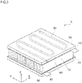
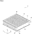
- Fig. 3 and 4 are perspective views of the electricity storage device stack 5, Fig. 4 showing it without cooling plates 50.
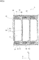
- Fig. 5 is a sectional side view of the electricity storage device stack 5.
- the electricity storage device stack 5 includes a plurality of electricity storage devices 10 arranged side by side, circuit boards 40, and cooling plates 50.
- Each electricity storage device 10 is provided with a cathode electrode terminal 12 and an anode electrode terminal 13 (see Fig. 6 ), both formed of metal.
- the electrode terminals 12 are arrayed on the top-face side of the electricity storage device stack 5, and the electrode terminals 13 are arrayed on the bottom-face side of the electricity storage device stack 5.
- the polarities, cathode or anode, of the electrode terminals 12 and 13 may be reversed.
- the circuit boards 40 are electrically connected to a plurality of electrode terminals 12 and 13, respectively, so that the plurality of electricity storage devices 10 can easily be connected in parallel with each other.
- the circuit boards 40 are disposed on the top and bottom faces, respectively, of the electricity storage devices 10 arranged side by side.
- Each circuit board 40 has slits 41, an electrode pattern 42, and a connection terminal 43.
- As many slits 41 as the number of electricity storage devices 10 arranged side by side are provided, and are arrayed along the Y direction (the direction along which the electricity storage devices 10 are arranged side by side).
- Each slit 41 is formed to penetrate the circuit board 40 along the Z direction (top-bottom direction), and extends along the X direction (see Fig. 5 ).
- an electrode pattern 42 to which a connection terminal 43 is connected is disposed on the top face of the circuit board 40 disposed on the top-face side of the electricity storage device stack 5.
- Peripheral seal portions 21 (described later) and the electrode terminals 12 are inserted through the slits 41.
- the peripheral seal portions 21 and the electrode terminals 12 inserted through the slits 41 are folded onto the top-face side of the circuit board 40.
- Tip parts of the electrode terminals 12 are bent to be electrically connected to the electrode pattern 42 by spot welding, soldering, or the like.
- the plurality of electrode terminals 12 are electrically connected to the connection terminal 43 via the electrode pattern 42.
- an electrode pattern (not illustrated) to which a connection terminal 43 is connected is disposed on the bottom face of the circuit board 40 disposed on the bottom-face side of the electricity storage device stack 5.
- Peripheral seal portions 21 and the electrode terminals 13 inserted through the slits 41 are folded onto the bottom-face side of the circuit board 40.
- Tip parts of the electrode terminals 13 are bent to be electrically connected to the electrode pattern by spot welding, soldering, or the like.
- the plurality of electrode terminals 13 are electrically connected to the connection terminal 43 via the electrode pattern (not illustrated).
- Folding the peripheral seal portions 21 allows reducing the height of the electricity storage device stack 5. While in this embodiment the tip parts of the electrode terminals 12 and 13 are bent to be electrically connected to the electrode patterns, the former may instead be electrically connected to the latter by welding, without being bent.
- the cooling plates 50 are disposed on the circuit boards 40 so as to lie in contact with the electrode terminals 12 and 13 respectively, and have refrigerant passages 51 inside them for circulation of refrigerant.
- To the refrigerant passages 51 are connected pipes extending from a radiator (not illustrated) mounted on the electric vehicle 1.
- the refrigerant is circulated by a refrigerant pump (not illustrated) to cool the electrode terminals 12 and 13 connected to the circuit boards 40.
- bending the tip parts of the electrode terminals 12 and 13 allows increasing the area over which they face the cooling plates 50 and thus enhances cooling efficiency.
- the cooling plates 50 may instead be disposed close to the electrode terminals 12 and 13.
- the electricity storage device stack 5 may be packed in a package container (not illustrated) to be formed into a package.
- the package container can be formed of a laminate material having a thermal adhesive resin layer, a metal foil, and a base layer laid over each other.
- the package container can be sealed by thermally bonding the thermal adhesive resin layer with the space between the electricity storage device stack 5 and the package container filled with a filling material (not illustrated).
- the package container may be formed as an injection-molded member.
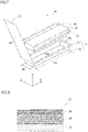
- Figs. 6 and 7 are a perspective view and an exploded perspective view, respectively, of the electricity storage device 10.
- Fig. 6 shows the electricity storage device 10 as it is before being built into the electricity storage device stack 5.
- the electricity storage device 10 is a secondary cell having an electricity storage element 11 sealed in a package member 20.
- Used as the electricity storage device 10 is, for example, a lithium-ion cell, a lithium-ion-polymer cell, an all-solid lithium-ion cell, a lead storage cell, a nickel-hydride storage cell, a nickel-cadmium storage cell, a nickel-iron storage cell, a nickel-zinc storage cell, a silver oxide-zinc storage cell, a metal-air cell, or a polyvalent cation cell.
- the electricity storage element 11 is formed by disposing a cathode plate and an anode plate (neither is shown) opposite each other across an electrically insulating separator (not shown). To the cathode and anode plates, electrode terminals 12 and 13 are connected respectively.
- the electricity storage element 11 can be formed by winding up a separator, a cathode plate, and an anode plate, all in an elongate form, laid over each other.
- the electricity storage element 11 can instead be formed by laying over each other a cathode plate, a separator, an anode plate, and a separator, all in a sheet form, in this order in a plurality of tiers.
- the electricity storage element 11 may instead be formed by folding up and thereby laying over each other a separator, a cathode plate, and an anode plate, all in an elongate form.
- an electrolyte is disposed between the cathode plate and the anode plate.
- the electrolyte is an electrolytic solution, and fills the inside of the package member 20.
- a solid electrolyte or a gel electrolyte may be used as the electrolyte.
- the package member 20 includes a packing material 15 and a packing material 25 each formed of a laminate material having a thermal adhesive resin layer 38 (see Fig. 8 ) on the inner face.
- Fig. 8 is a sectional view showing the layered structure of the packing material 15.
- the packing material 25 has the same layered structure as the packing material 15.
- the packing materials 15 and 25 are each formed by laying over each other a base layer 34, a barrier layer 36, and the thermal adhesive resin layer 38 in this order.
- the packing materials 15 and 25 are preferably given a thickness of 50 ⁇ m or more with consideration given to mechanical strength, but 400 ⁇ m or less with consideration given to reducing the weight of the electricity storage device 10.
- the base layer 34 is electrically insulating, and is formed of resin film such as of nylon, polyester, or polyethylene terephthalate.
- the thickness of base layer 34 is, for example, 10 ⁇ m or more but 75 ⁇ m or less.
- the base layer 34 is preferably formed of a uniaxially stretched film or a biaxially stretched film.
- the base layer 34 may be formed by laying over each other a plurality of resin films of different materials. In that case, the plurality of resin films are bonded together with polyurethane-based, acrylic, or other adhesive.
- the base layer 34 is formed by laying together polyethylene terephthalate (with a thickness of 12 ⁇ m) and nylon (with a thickness of 15 ⁇ m) with adhesive (with a thickness of 4 ⁇ m).
- the barrier layer 36 is formed of a metal foil, and prevents entry of moisture, oxygen, light, and the like.
- the metal for forming the barrier layer 36 include aluminum, aluminum alloys, stainless steel, and titanium.
- the thickness of the barrier layer 36 is, for example, 10 ⁇ m or more but 300 ⁇ m or less.
- the base layer 34 and the barrier layer 36 are bonded together with polyurethane-based, acrylic, or other adhesive (not shown).
- the barrier layer 36 is formed of an aluminum foil with a thickness of 40 ⁇ m.
- the thermal adhesive resin layer 38 may be formed of any resin that is thermally adhesive, and is formed of a thermally adhesive resin such as polypropylene, acid-modified polypropylene, low-density polyethylene, or straight-chain low-density polyethylene.
- the thermal adhesive resin layer 38 may be formed by laying over each other a plurality of resin layers of different materials.
- the thickness of the thermal adhesive resin layer 38 is, for example, 10 ⁇ m or more but 100 ⁇ m or less.
- the thermal adhesive resin layer 38 is formed by extrusion over the barrier layer 36. A film with which to form the thermal adhesive resin layer 38 may be bonded over the barrier layer 36 with adhesive.
- the thermal adhesive resin layer 38 is formed by extruding acid-modified polypropylene (with a thickness of 40 ⁇ m) and polypropylene (with a thickness of 40 ⁇ m) in this order over the barrier layer 36.
- the package member 20 has the packing materials 15 and 25 formed continuously along the X direction into a single piece.
- the packing material 15 has a housing portion 16 and a flange portion 17.
- the packing material 15 has the housing portion 16 formed by cold-forming so as to be recessed with a predetermined depth relative to the flange portion 17.
- the housing portion 16 has, in one face of it, a substantially rectangular opening 16a, where the electricity storage element 11 is housed.
- the flange portion 17 is formed to protrude outward from the circumferential edge of the opening 16a.
- the packing material 25 is formed in a rectangular sheet form.
- the packing material 25 is thermally bonded to the flange portion 17 to form a lid portion 18 that covers the opening 16a.
- the electrode terminals 12 and 13 can be given a larger width in proportion to the dimension Ax of the opening 16a along its longer-side (longitudinal) direction, and it is thereby possible to increase the electrical conductivity of the electrode terminals 12 and 13. It is hence possible to reduce heat generation in the electrode terminals 12 and 13. This permits application of a higher voltage during charging and thus allows faster charging. It is also possible, by reducing heat generation in the electrode terminals 12 and 13 and in the electricity storage element 11, to alleviate their deterioration. It is thus possible to provide an electricity storage device 10 that is less prone to deterioration through repeated charging and discharging with a high voltage.
- the electricity storage device 10 can be used suitably as a motive power source in BEVs (battery electric vehicles) and PHEVs (plug-in hybrid electric vehicles) as well as HEVs (hybrid electric vehicles) and microhybrid vehicles with a 48-volt power supply.
- BEVs battery electric vehicles
- PHEVs plug-in hybrid electric vehicles
- HEVs hybrid electric vehicles
- microhybrid vehicles with a 48-volt power supply.
- the width L of the electrode terminals 12 and 13 along the X direction is greater than one-half of the dimension Ax of the opening 16a along its longer-side direction.
- the electrode terminals 12 and 13 are given a large width L compared with the capacity of the electricity storage device 10. This helps further reduce heat generation in the electrode terminals 12 and 13.
- the electrode terminals 12 and 13 are given a width L of 5 cm or more but 100 cm or less, preferably 10 cm or more but 100 cm or less, and more preferably 15 cm or more but 100 cm or less. Giving the electrode terminals 12 and 13 a width L more than 100 cm leads to lower sealing performance around the electrode terminals 12 and 13.
- the electrode terminals 12 and 13 are held between the flange portion 17 and the lid portion 18 via a tab film (not illustrated) that is thermally adhesive. This helps enhance sealing performance around the electrode terminals 12 and 13.
- the dimension Ax of the opening 16a along its longer-side direction is 1.5 times or more but 30 times or less of its dimension Az along its shorter-side (lateral) direction.
- a dimension Ax less than 1.5 times the dimension Az leads to the electricity storage device 10 having a low capacity; giving the electricity storage device 10 a dimension Ax 1.5 times or more of the dimension Az permits it to have a high capacity.
- a dimension Ax more than 30 times the dimension Az makes the packing material 15 difficult to mold, and leads to a low yield rate; designing the dimension Ax to be 30 times or less of the dimension Az allows molding the packing material 15 at an improved yield rate.
- designing the dimension Ax to be large compared with the dimension Az permits the electrode terminals 12 and 13 to have a greater width L, and leads to further enhanced electrical conductivity.
- the electrode terminals 12 and 13 protrude outward from the outer edge of the flange portion 17 by 0.5 mm or more but 50 mm or less. If the electrode terminals 12 and 13 protrude from the outer edge of the flange portion 17 by more than 50 mm, that leads to low electrical conductivity. On the other hand, if they protrude from the outer edge of the flange portion 17 by less than 0.5 mm, that makes it difficult to connect the electrode terminals 12 and 13 to the circuit board 40.
- the depth Ay of the housing portion 16 is determined according to the thickness of the barrier layer 36 in the packing material 15 so as not to develop cracks or the like during molding.
- the housing portion 16 is given a depth of 5 mm to 10 mm compared with the barrier layer 36 with a thickness of 40 ⁇ m.
- the housing portion 16 is formed so as to have, on planes perpendicular to the depth direction, corners rounded with a radius R of, for example, about 3 mm and, on planes parallel to the depth direction, corners rounded with a radius R of, for example, about 1.5 mm.
- Increasing the thickness of the barrier layer 36 permits giving the housing portion 16 a depth of, for example, 5 mm to 30 mm.
- the electricity storage device 10 is disposed with the depth direction (Y direction) of the housing portion 16 aligned with the front-rear direction of the electric vehicle 1.
- the longer-side direction (X direction) of the opening 16a is aligned with the left-right direction of the electric vehicle 1, and the shorter-side direction (Z direction) of the opening 16a is aligned with the height direction of the electric vehicle 1.
- the housing portion 16 Since the housing portion 16 is formed by cold-forming, its depth is difficult to increase. By contrast, the dimensions Ax and Az of the opening 16a along the two directions are easier to increase than its depth Ay along the depth direction. Accordingly, aligning the depth direction (Y direction) of the housing portion 16 with the front-rear direction of the electric vehicle 1 permits a plurality of electricity storage devices 10 to be installed without being stacked on each other to achieve the supply of desired electric power. It is thus possible to prevent breakage of the package member 20 due to increased weight resulting from stacking, and to enhance the reliability of the electricity storage device 10.
- aligning the shorter-side direction (Z direction) of the housing portion 16 with the height direction helps reduce the height of the electricity storage device 10 and enhance cabin comfort in the electric vehicle 1.
- the housing portion 16 is elongate along the X direction with its dimension Ax along the X direction greater than its dimension Az along the Z direction, it is possible to produce an electricity storage device 10 with a high capacity while restraining its height.
- the electricity storage device stack 5 is given a height of, for example, 100 mm or less. In a case where the electric vehicle 1 is of an SUV type or a one-box type, the electricity storage device stack 5 is given a height of, for example, 150 mm or less.
- the machine direction (MD) of the package member 20 (packing materials 15 and 25) is aligned with the Z direction (the direction orthogonal to the width direction of the electrode terminals 12 and 13). Folding a laminate material along a direction parallel to the machine direction tends to produce cracks in a metal foil and pinholes in a resin film.
- the machine direction of the packing materials 15 and 25 being orthogonal to the width direction of the electrode terminals 12 and 13, it is possible, when folding the peripheral seal portions 21 along the X direction as shown in Fig. 5 referred to previously, to prevent cracks and pinholes from developing in the package member 20.
- the machine direction (MD) of the packing materials 15 and 25 corresponds to the rolling direction (RD) of the metal foil (such as a foil of an aluminum alloy) of the barrier layer 36.
- the transverse direction TD of the packing materials 15 and 25 corresponds to the transverse direction TD of the metal foil. It is possible to discriminate the rolling direction (RD) of a metal foil based on rolling traces.
- the thermal adhesive resin layer 38 in the packing materials 15 and 25 under an electron microscope to recognize a sea-island structure in order to identify as the MD the direction parallel to the sectional plane which has the maximum value of the average diameter of islands along the direction perpendicular to the thickness direction of the thermal adhesive resin layer 38.
- This method serves to identify the MD in a case where the MD of the packing materials 15 and 25 cannot be identified based on rolling traces on the metal foil.
- the thermal adhesive resin layer 38 is inspected to recognize a sea-island structure under an electron microscope on each of the following sectional planes (a total of 10 sectional planes): sectional planes in 10 directions 10-degrees apart from each other, the ten directions including the length direction of the thermal adhesive resin layer 38, the direction perpendicular to the length direction of the thermal adhesive resin layer 38, and eight directions between those two directions. Then for each island on each sectional plane, the diameter d of the island defined by a straight-line distance between opposite ends along the direction perpendicular to the thickness direction of the thermal adhesive resin layer 38 is measured. Next, for each sectional plane, the average of the 20 greatest island diameters d is calculated. The direction parallel to the sectional plane with the greatest average of island diameters d is identified as the MD.
- Fig. 9 is a diagram illustrating a procedure for fabricating the electricity storage device 10.
- the electricity storage device 10 is produced through a process of preparing the package member 20 by molding, followed by a process of packing the electricity storage element 11 in the package member 20.
- a plurality of recesses as housing portions 16 are formed at predetermined intervals in a laminate material in the form of a roll, in one end part of it along its width direction. This produces, along the machine direction (MD), a plurality of pairs of packing materials 15 and 25, each pair being continuous along the width direction.
- the packing materials 15 and 25 are formed with the machine direction (MD) of the roll-form laminate material aligned with the Z direction.
- the housing portion 16 having the electricity storage element 11 housed in it is filled with an electrolytic solution.
- the packing material 25 is folded to cover the opening 16a, and the lid portion 18 of the packing material 25 is thermally bonded to the flange portion 17 of the packing material 15 (see Fig. 7 ).
- a peripheral seal portion 21 is formed along the circumference of the housing portion 16 and the housing portion 16 is sealed. In this way, the electricity storage element 11 is packed in the package member 20.
- Fig. 10 is a diagram illustrating a modified example of the procedure for fabricating the electricity storage device 10.
- a laminate material in the form of a small-width roll is used, by cold-forming, a plurality of recesses as the housing portion 16 are formed at a predetermined intervals along the machine direction (MD).
- MD machine direction
- the packing materials 15 and 25 are formed with the machine direction (MD) of the roll-form laminate material aligned with the X direction.
- packing materials 15 and 25 are formed to be continuous, the packing materials 15 and 25 may instead be formed out of separate laminate materials each in the form of a roll.
- a housing portion 16 of a package member 20 in which an electricity storage element 11 is housed has in one face of it a substantially rectangular opening 16a.
- the electricity storage element 11 has a pair of electrode terminals 12 and 13 protruding outward from opposite longer-side edges of the opening 16a. This makes it possible to fabricate the electricity storage element 11 with a reduced distance between the opposed electrode terminals 12 and 13. This helps reduce the internal resistance of the electricity storage element 11 during charging and discharging, and it is thus possible to provide an electricity storage device 10 capable of high-output discharging and high-speed charging.
- the electrode terminals 12 and 13 can be formed with a larger width in proportion to the dimension of the opening 16a along its longer-side direction, and this increases electrical conductivity. It is thus possible to apply a higher voltage during charging and further reduce the charging time. It is also possible to reduce heat generation in the electrode terminals 12 and 13 and in the electricity storage element 11 and alleviate their deterioration.
- the width L of the electrode terminals 12 and 13 is greater than one-half of the dimension Ax of the opening 16a along its longer-side direction.
- the dimension Ax of the opening 16a is 1.5 times or more but 30 times or less of the dimension Az of the opening 16a along its shorter-side direction.
- the width of the electrode terminals 12 and 13 is 5 cm or more but 100 cm or less.
- the electrode terminals 12 and 13 protrude from the outer edge of the flange portion 17 by 0.5 mm or more but 50 mm or less. It is thus possible to increase the electrical conductivity of the electrode terminals 12 and 13 while giving the electricity storage device 10 a satisfactory capacity.
- the machine direction (MD) of the package member 20 (packing materials 15 and 25) is aligned with the Z direction (the direction orthogonal to the width direction of the electrode terminals 12 and 13). It is thus possible, when folding a peripheral seal portion 21 along the X direction, to prevent cracks and pinholes from developing in the package member 20.
- An electricity storage device stack 5 having a plurality of electricity storage devices 10 arranged side by side along the depth direction (Y direction) of the housing portion 16 includes circuit boards 40 electrically connected to the electrode terminals 12 and 13 arrayed along the Y direction.
- the circuit boards 40 have slits 41 through which the electrode terminals 12 and 13 are inserted and electrode patterns 42 electrically connected to the electrode terminals 12 and 13 so inserted. It is thus possible to easily arrange the plurality of electricity storage devices 10 side by side.
- Tip parts of the electrode terminals 12 and 13 protruding through the slits 41 are bent to be electrically connected to the electrode patterns 42. It is thus possible to reduce the height of the electricity storage device stack 5.
- the electricity storage device stack further includes cooling plates 50 having inside them refrigerant passages 51 through which refrigerant is circulated and disposed over the circuit boards 40. It is thus possible to cool the electrode terminals 12 and 13 efficiently.
- the electricity storage device 10 is disposed with the depth direction (Y direction) of the housing portion 16 aligned with the front-rear direction of the electric vehicle (mobile body) 1.
- the longer-side direction (X direction) of the opening 16a is aligned with the front-rear direction of the electric vehicle (mobile body) 1
- the shorter-side direction (Z direction) of the opening 16a is aligned with the height direction of the electric vehicle (mobile body) 1.
- Fig. 11 is an exploded perspective view of an electricity storage device 10 according to a second embodiment.
- FIG. 11 differs from the first embodiment in the shape of the packing material 25, and is otherwise similar to the first embodiment.
- the packing material 25 has a housing portion 26 and a flange portion 27.
- the housing portion 26 has, in one face of it, a substantially rectangular opening 26a.
- the electricity storage element 11 is housed in the housing portion 16 of the packing material 15 and the housing portion 26 of the packing material 25.
- the flange portion 27 is formed to protrude outward from the circumferential edge of the opening 26a.
- the thermal adhesive resin layers 38 (see Fig. 6 ) in the flange portions 17 and 27 are thermally bonded together to form an annular peripheral seal portion 21 along the circumference of the housing portions 16 and 26.
- the housing portions 16 and 26, which are formed with a predetermined depth from the inner edge of the peripheral seal portion 21, are sealed by the peripheral seal portion 21.
- the total depth of the housing portions 16 and 26 is preferably 30 mm or less.
- the electricity storage device 10 is disposed with the depth direction (Y direction) of the housing portions 16 and 26 aligned with the front-rear direction of the electric vehicle 1.
- the longer-side direction (X direction) of the opening 26a is aligned with the left-right direction of the electric vehicle 1, and its shorter-side direction (Z direction) is aligned with the height direction of the electric vehicle 1.
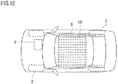
- Fig. 12 is a top view of an electric vehicle 1 according to a third embodiment.
- Figs. 1 to 10 are identified by the same reference signs.
- This embodiment differs from the first embodiment in how the electricity storage device stack 5 is disposed, and is otherwise similar to the first embodiment.
- the electricity storage device stack 5 is installed under the floor of the body of the electric vehicle 1, and is disposed such that the direction along which the electricity storage devices 10 are arranged side by side is aligned with the left-right direction of the electric vehicle 1.
- the electricity storage device 10 is disposed with the depth direction (Y direction) of the housing portion 16 (see Fig. 6 ) aligned with the left-right direction of the electric vehicle 1.
- the longer-side direction (X direction) of the opening 16a is aligned with the front-rear direction of the electric vehicle 1, and the shorter-side direction (Z direction) of the opening 16a is aligned with the height direction of the electric vehicle 1.
- the electricity storage devices 10 according to the second embodiment may be installed in the electric vehicle 1 such that the direction in which the electricity storage devices 10 are arranged side by side is aligned with the left-right direction of the electric vehicle 1.
- the electricity storage device 10 that supplies the driving motor 3 with electric power is a secondary battery, it may instead be a capacitor (electrolytic capacitor, electrical double layer capacitor, lithium-ion capacitor, or the like).
- the electricity storage device stack 5 may be incorporated in any other mobile bodies.
- the electricity storage device stack 5 can be incorporated in two-legged robots, railway cars, aircrafts, helicopters, drones, agricultural machines, construction machines, and the like.
- the depth direction (Y direction) of the housing portion 16 of the electricity storage device 10 may be aligned with the height direction of the body of the mobile body.
- a plurality of electricity storage devices 10 are stacked along the height direction of the mobile body, and the electrode terminals 12 and 13 extend in a horizontal direction. This helps prevent a lopsided distribution of the electrolyte filling inside the package member 20 around one of the electrode terminals 12 and 13.
- the electricity storage device 10 and the electricity storage device stack 5 may be used other than as a driving source for a mobile body. They may be used as stationary electric power sources in, for example, energy storage systems, battery energy storage systems, and uninterruptible power supplies.
- the present invention finds applications widely in mobile bodies that incorporate electricity storage devices.
Landscapes
- Engineering & Computer Science (AREA)
- Power Engineering (AREA)
- Chemical & Material Sciences (AREA)
- Chemical Kinetics & Catalysis (AREA)
- Electrochemistry (AREA)
- General Chemical & Material Sciences (AREA)
- Microelectronics & Electronic Packaging (AREA)
- Manufacturing & Machinery (AREA)
- Transportation (AREA)
- Mechanical Engineering (AREA)
- Sustainable Energy (AREA)
- Sustainable Development (AREA)
- Life Sciences & Earth Sciences (AREA)
- Combustion & Propulsion (AREA)
- Sealing Battery Cases Or Jackets (AREA)
- Nonmetal Cutting Devices (AREA)
- Manufacturing Of Magnetic Record Carriers (AREA)
- Secondary Cells (AREA)
- Battery Mounting, Suspending (AREA)
- Electric Double-Layer Capacitors Or The Like (AREA)
- Connection Of Batteries Or Terminals (AREA)
Abstract
Description
- The present invention relates to electricity storage devices, and also relates to electricity storage device stacks and mobile bodies that employ electricity storage devices.
- A known electricity storage device is disclosed in
Patent Document 1. This electricity storage device has an electricity storage element sealed in a package member. The electricity storage element has a cathode plate and an anode plate disposed opposite each other across a separator, with an electrolyte filling between the cathode and anode plates. The cathode and anode plates have electrode terminals connected to them respectively, with the electrode terminals protruding out of the package member. - Patent Document 1:
JP 3852110 Fig. 1 ) - Inconveniently, with the known electricity storage device mentioned above, as the distance between the opposed electrode terminals increases, the internal resistance of the electricity storage element increases. This results in a drop in output during discharging, and in a prolonged time to complete charging.
- An object of the present invention is to provide an electricity storage device capable of high-output discharging as well as high-speed charging, and to provide an electricity storage device stack and a mobile body employing such an electricity storage device.
- To achieve the above object, according to one aspect of the present invention, an electricity storage device has an electricity storage element sealed in a package member formed of a laminate material including a thermal adhesive resin layer. The package member has: a housing portion having in one face of it a substantially rectangular opening and formed to have a predetermined depth, for housing the electricity storage element; a flange portion protruding outward from a circumferential edge of the opening; and a lid portion covering the opening and thermally bonded to the flange portion. The electricity storage element has a pair of electrode terminals protruding outward respectively from opposite longer-side edges of the opening and held between the flange portion and the lid portion.
- According to another aspect of the present invention, in an electricity storage device configured as described above, a width of the electrode terminals may be greater than one-half of a dimension of the opening along its longer-side direction.
- According to another aspect of the present invention, in an electricity storage device configured as described above, a dimension of the opening along its longer-side direction may be 1.5 times or more but 30 times or less of a dimension of the opening along its shorter-side direction.
- According to another aspect of the present invention, in an electricity storage device configured as described above, a width of the electrode terminals may be 5 cm or more but 100 cm or less.
- According to another aspect of the present invention, in an electricity storage device configured as described above, the electrode terminals may protrude from an outer edge of the flange portion by 0.5 mm or more but 50 mm or less.
- According to another aspect of the present invention, in an electricity storage device configured as described above, a machine direction of the package member may be orthogonal to a width direction of the electrode terminals.
- According to another aspect of the present invention, an electricity storage device stack includes: a plurality of electricity storage devices configured as described above arranged side by side along a depth direction of the housing portion; and a circuit board electrically connected to the electrode terminals arrayed along the depth direction of the housing portion. The circuit board has: slits through which the electrode terminals are inserted; and an electrode pattern electrically connected to the electrode terminals inserted through the slits.
- According to another aspect of the present invention, in an electricity storage device stack configured as described above, tip parts of the electrode terminals protruding through the slits may be bent to be electrically connected to the electrode pattern.
- According to another aspect of the present invention, in an electricity storage device stack configured as described above, there may be further provided a cooling plate having inside it a refrigerant passage through which refrigerant is circulated. The cooling plate may be disposed over the circuit board so as to lie in contact with or close to the electrode terminals.
- According to another aspect of the present invention, a mobile body includes: an electricity storage device stack configured as described above; and a driving motor supplied with electric power from the electricity storage device stack. The mobile body is driven by the driving motor. The depth direction of the housing portion is aligned with a front-rear direction of a body of the mobile body. A longer-side direction of the opening is aligned with a left-right direction of the body of the mobile body. A shorter-side direction of the opening is aligned with a height direction of the body of the mobile body.
- According to another aspect of the present invention, a mobile body includes: an electricity storage device stack configured as described above; and a driving motor supplied with electric power from the electricity storage device stack. The mobile body is driven by the driving motor. The depth direction of the housing portion is aligned with a left-right direction of a body of the mobile body. A longer-side direction of the opening is aligned with a front-rear direction of the body of the mobile body. A shorter-side direction of the opening is aligned with a height direction of the body of the mobile body.
- According to another aspect of the present invention, a mobile body includes: an electricity storage device stack configured as described above; and a driving motor supplied with electric power from the electricity storage device stack. The mobile body is driven by the driving motor. The depth direction of the housing portion is aligned with a height direction of the body of the mobile body.
- According to the present invention, a housing portion of a package member in which an electricity storage element is housed has in one face of it a substantially rectangular opening and is covered by a lid portion. The electricity storage element has a pair of electrode terminals protruding outward from opposite longer-side edges of the opening. This makes it possible to fabricate the electricity storage element with a reduced distance between the opposed electrode terminals. This helps reduce the internal resistance of the electricity storage element during charging and discharging, and it is thus possible to provide an electricity storage device capable of high-output discharging and high-speed charging, and to provide an electricity storage device stack and a mobile body that employ such an electricity storage device. Moreover, the electrode terminals can be formed with a larger width in proportion to the dimension of the opening along its longer-side direction, and this increases electrical conductivity. It is thus possible to apply a higher voltage and further reduce the charging time. It is also possible to reduce heat generation in the electrode terminals and in the electricity storage element and alleviate their deterioration.
-
-
Fig. 1 is a side view of an electric vehicle according to a first embodiment of the present invention. -
Fig. 2 is a top view of the electric vehicle according to the first embodiment of the present invention. -
Fig. 3 is a perspective view of an electricity storage device stack in the electric vehicle according to the first embodiment of the present invention. -
Fig. 4 is a perspective view of the electricity storage device stack in the electric vehicle according to the first embodiment of the present invention. -
Fig. 5 is a sectional side view of the electricity storage device stack in the electric vehicle according to the first embodiment of the present invention -
Fig. 6 is a perspective view of an electricity storage device in the electric vehicle according to the first embodiment of the present invention. -
Fig. 7 is an exploded perspective view of the electricity storage device in the electric vehicle according to the first embodiment of the present invention. -
Fig. 8 is a sectional view showing the layered structure of a packing material for a package member of the electricity storage device in the electric vehicle according to the first embodiment of the present invention. -
Fig. 9 is a diagram illustrating a procedure of fabricating the electricity storage device in the electric vehicle according to the first embodiment of the present invention. -
Fig. 10 is a diagram illustrating a modified example of the procedure of fabricating the electricity storage device in the electric vehicle according to the first embodiment of the present invention. -
Fig. 11 is an exploded perspective view of an electricity storage device in an electric vehicle according to a second embodiment of the present invention. -
Fig. 12 is a top view of an electric vehicle according to a third embodiment of the present invention. - Embodiments of the present invention will be described below with reference to the accompanying drawings.
Figs. 1 and 2 are a side view and a top view, respectively, of an electric vehicle according to a first embodiment. The electric vehicle (mobile body) 1 includes adriving motor 3 as a motive power source for drivingwheels 2. The Under the floor of the body of the electric vehicle 1 (the body of the mobile body), an electricitystorage device stack 5 is installed as a driving source for supplying the drivingmotor 3 with electric power. -
Fig. 3 and4 are perspective views of the electricitystorage device stack 5,Fig. 4 showing it without coolingplates 50.Fig. 5 is a sectional side view of the electricitystorage device stack 5. The electricitystorage device stack 5 includes a plurality ofelectricity storage devices 10 arranged side by side,circuit boards 40, andcooling plates 50. - Each
electricity storage device 10 is provided with acathode electrode terminal 12 and an anode electrode terminal 13 (seeFig. 6 ), both formed of metal. When theelectricity storage devices 10 are arrayed, theelectrode terminals 12 are arrayed on the top-face side of the electricitystorage device stack 5, and theelectrode terminals 13 are arrayed on the bottom-face side of the electricitystorage device stack 5. The polarities, cathode or anode, of theelectrode terminals - The
circuit boards 40 are electrically connected to a plurality ofelectrode terminals electricity storage devices 10 can easily be connected in parallel with each other. Thecircuit boards 40 are disposed on the top and bottom faces, respectively, of theelectricity storage devices 10 arranged side by side. Eachcircuit board 40 hasslits 41, anelectrode pattern 42, and aconnection terminal 43. Asmany slits 41 as the number ofelectricity storage devices 10 arranged side by side are provided, and are arrayed along the Y direction (the direction along which theelectricity storage devices 10 are arranged side by side). Each slit 41 is formed to penetrate thecircuit board 40 along the Z direction (top-bottom direction), and extends along the X direction (seeFig. 5 ). - On the top face of the
circuit board 40 disposed on the top-face side of the electricitystorage device stack 5, anelectrode pattern 42 to which aconnection terminal 43 is connected is disposed. Peripheral seal portions 21 (described later) and theelectrode terminals 12 are inserted through theslits 41. Theperipheral seal portions 21 and theelectrode terminals 12 inserted through theslits 41 are folded onto the top-face side of thecircuit board 40. Tip parts of theelectrode terminals 12 are bent to be electrically connected to theelectrode pattern 42 by spot welding, soldering, or the like. Thus, the plurality ofelectrode terminals 12 are electrically connected to theconnection terminal 43 via theelectrode pattern 42. - On the bottom face of the
circuit board 40 disposed on the bottom-face side of the electricitystorage device stack 5, an electrode pattern (not illustrated) to which aconnection terminal 43 is connected is disposed.Peripheral seal portions 21 and theelectrode terminals 13 inserted through theslits 41 are folded onto the bottom-face side of thecircuit board 40. Tip parts of theelectrode terminals 13 are bent to be electrically connected to the electrode pattern by spot welding, soldering, or the like. Thus, the plurality ofelectrode terminals 13 are electrically connected to theconnection terminal 43 via the electrode pattern (not illustrated). - Folding the
peripheral seal portions 21 allows reducing the height of the electricitystorage device stack 5. While in this embodiment the tip parts of theelectrode terminals - The cooling
plates 50 are disposed on thecircuit boards 40 so as to lie in contact with theelectrode terminals refrigerant passages 51 inside them for circulation of refrigerant. To therefrigerant passages 51 are connected pipes extending from a radiator (not illustrated) mounted on theelectric vehicle 1. The refrigerant is circulated by a refrigerant pump (not illustrated) to cool theelectrode terminals circuit boards 40. Here, bending the tip parts of theelectrode terminals plates 50 and thus enhances cooling efficiency. The coolingplates 50 may instead be disposed close to theelectrode terminals - The electricity
storage device stack 5 may be packed in a package container (not illustrated) to be formed into a package. In that case, the package container can be formed of a laminate material having a thermal adhesive resin layer, a metal foil, and a base layer laid over each other. The package container can be sealed by thermally bonding the thermal adhesive resin layer with the space between the electricitystorage device stack 5 and the package container filled with a filling material (not illustrated). Or the package container may be formed as an injection-molded member. -
Figs. 6 and7 are a perspective view and an exploded perspective view, respectively, of theelectricity storage device 10.Fig. 6 shows theelectricity storage device 10 as it is before being built into the electricitystorage device stack 5. Theelectricity storage device 10 is a secondary cell having anelectricity storage element 11 sealed in apackage member 20. Used as theelectricity storage device 10 is, for example, a lithium-ion cell, a lithium-ion-polymer cell, an all-solid lithium-ion cell, a lead storage cell, a nickel-hydride storage cell, a nickel-cadmium storage cell, a nickel-iron storage cell, a nickel-zinc storage cell, a silver oxide-zinc storage cell, a metal-air cell, or a polyvalent cation cell. - The
electricity storage element 11 is formed by disposing a cathode plate and an anode plate (neither is shown) opposite each other across an electrically insulating separator (not shown). To the cathode and anode plates,electrode terminals electricity storage element 11 can be formed by winding up a separator, a cathode plate, and an anode plate, all in an elongate form, laid over each other. Theelectricity storage element 11 can instead be formed by laying over each other a cathode plate, a separator, an anode plate, and a separator, all in a sheet form, in this order in a plurality of tiers. Theelectricity storage element 11 may instead be formed by folding up and thereby laying over each other a separator, a cathode plate, and an anode plate, all in an elongate form. - Between the cathode plate and the anode plate, an electrolyte is disposed. In this embodiment, the electrolyte is an electrolytic solution, and fills the inside of the
package member 20. As the electrolyte, a solid electrolyte or a gel electrolyte may be used. - The
package member 20 includes a packingmaterial 15 and a packingmaterial 25 each formed of a laminate material having a thermal adhesive resin layer 38 (seeFig. 8 ) on the inner face. -
Fig. 8 is a sectional view showing the layered structure of the packingmaterial 15. The packingmaterial 25 has the same layered structure as the packingmaterial 15. The packingmaterials base layer 34, abarrier layer 36, and the thermaladhesive resin layer 38 in this order. The packingmaterials electricity storage device 10. - The
base layer 34 is electrically insulating, and is formed of resin film such as of nylon, polyester, or polyethylene terephthalate. The thickness ofbase layer 34 is, for example, 10 µm or more but 75 µm or less. For enhanced heat resistance, thebase layer 34 is preferably formed of a uniaxially stretched film or a biaxially stretched film. - For enhanced pinhole resistance, enhanced electrical insulation, and the like, the
base layer 34 may be formed by laying over each other a plurality of resin films of different materials. In that case, the plurality of resin films are bonded together with polyurethane-based, acrylic, or other adhesive. In this embodiment, thebase layer 34 is formed by laying together polyethylene terephthalate (with a thickness of 12 µm) and nylon (with a thickness of 15 µm) with adhesive (with a thickness of 4 µm). - The
barrier layer 36 is formed of a metal foil, and prevents entry of moisture, oxygen, light, and the like. Examples of the metal for forming thebarrier layer 36 include aluminum, aluminum alloys, stainless steel, and titanium. The thickness of thebarrier layer 36 is, for example, 10 µm or more but 300 µm or less. Thebase layer 34 and thebarrier layer 36 are bonded together with polyurethane-based, acrylic, or other adhesive (not shown). In this embodiment, thebarrier layer 36 is formed of an aluminum foil with a thickness of 40 µm. - The thermal
adhesive resin layer 38 may be formed of any resin that is thermally adhesive, and is formed of a thermally adhesive resin such as polypropylene, acid-modified polypropylene, low-density polyethylene, or straight-chain low-density polyethylene. The thermaladhesive resin layer 38 may be formed by laying over each other a plurality of resin layers of different materials. The thickness of the thermaladhesive resin layer 38 is, for example, 10 µm or more but 100 µm or less. The thermaladhesive resin layer 38 is formed by extrusion over thebarrier layer 36. A film with which to form the thermaladhesive resin layer 38 may be bonded over thebarrier layer 36 with adhesive. - In this embodiment, the thermal
adhesive resin layer 38 is formed by extruding acid-modified polypropylene (with a thickness of 40 µm) and polypropylene (with a thickness of 40 µm) in this order over thebarrier layer 36. - In
Figs. 6 and7 , thepackage member 20 has the packingmaterials material 15 has ahousing portion 16 and aflange portion 17. The packingmaterial 15 has thehousing portion 16 formed by cold-forming so as to be recessed with a predetermined depth relative to theflange portion 17. Thehousing portion 16 has, in one face of it, a substantiallyrectangular opening 16a, where theelectricity storage element 11 is housed. Theflange portion 17 is formed to protrude outward from the circumferential edge of theopening 16a. The packingmaterial 25 is formed in a rectangular sheet form. The packingmaterial 25 is thermally bonded to theflange portion 17 to form alid portion 18 that covers theopening 16a. - Thermal bonding is performed with the
electrode terminals opening 16a, in a state held between theflange portion 17 and thelid portion 18. In designing theelectricity storage element 11, reducing the distance between each pair ofelectrode terminals electricity storage device 10 capable of high-output discharging as well as high-speed charging. - The
electrode terminals opening 16a along its longer-side (longitudinal) direction, and it is thereby possible to increase the electrical conductivity of theelectrode terminals electrode terminals electrode terminals electricity storage element 11, to alleviate their deterioration. It is thus possible to provide anelectricity storage device 10 that is less prone to deterioration through repeated charging and discharging with a high voltage. Moreover, allowing quick charging and discharging with a high voltage for a short time, theelectricity storage device 10 can be used suitably as a motive power source in BEVs (battery electric vehicles) and PHEVs (plug-in hybrid electric vehicles) as well as HEVs (hybrid electric vehicles) and microhybrid vehicles with a 48-volt power supply. - The width L of the
electrode terminals opening 16a along its longer-side direction. Thus, theelectrode terminals electricity storage device 10. This helps further reduce heat generation in theelectrode terminals electrode terminals electrode terminals 12 and 13 a width L more than 100 cm leads to lower sealing performance around theelectrode terminals electrode terminals flange portion 17 and thelid portion 18 via a tab film (not illustrated) that is thermally adhesive. This helps enhance sealing performance around theelectrode terminals - The dimension Ax of the
opening 16a along its longer-side direction is 1.5 times or more but 30 times or less of its dimension Az along its shorter-side (lateral) direction. A dimension Ax less than 1.5 times the dimension Az leads to theelectricity storage device 10 having a low capacity; giving the electricity storage device 10 a dimension Ax 1.5 times or more of the dimension Az permits it to have a high capacity. On the other hand, a dimension Ax more than 30 times the dimension Az makes the packingmaterial 15 difficult to mold, and leads to a low yield rate; designing the dimension Ax to be 30 times or less of the dimension Az allows molding the packingmaterial 15 at an improved yield rate. Moreover, designing the dimension Ax to be large compared with the dimension Az permits theelectrode terminals - The
electrode terminals flange portion 17 by 0.5 mm or more but 50 mm or less. If theelectrode terminals flange portion 17 by more than 50 mm, that leads to low electrical conductivity. On the other hand, if they protrude from the outer edge of theflange portion 17 by less than 0.5 mm, that makes it difficult to connect theelectrode terminals circuit board 40. - The depth Ay of the
housing portion 16 is determined according to the thickness of thebarrier layer 36 in the packingmaterial 15 so as not to develop cracks or the like during molding. In this embodiment, thehousing portion 16 is given a depth of 5 mm to 10 mm compared with thebarrier layer 36 with a thickness of 40 µm. Here, thehousing portion 16 is formed so as to have, on planes perpendicular to the depth direction, corners rounded with a radius R of, for example, about 3 mm and, on planes parallel to the depth direction, corners rounded with a radius R of, for example, about 1.5 mm. Increasing the thickness of thebarrier layer 36 permits giving thehousing portion 16 a depth of, for example, 5 mm to 30 mm. - The
electricity storage device 10 is disposed with the depth direction (Y direction) of thehousing portion 16 aligned with the front-rear direction of theelectric vehicle 1. The longer-side direction (X direction) of theopening 16a is aligned with the left-right direction of theelectric vehicle 1, and the shorter-side direction (Z direction) of theopening 16a is aligned with the height direction of theelectric vehicle 1. - Since the
housing portion 16 is formed by cold-forming, its depth is difficult to increase. By contrast, the dimensions Ax and Az of theopening 16a along the two directions are easier to increase than its depth Ay along the depth direction. Accordingly, aligning the depth direction (Y direction) of thehousing portion 16 with the front-rear direction of theelectric vehicle 1 permits a plurality ofelectricity storage devices 10 to be installed without being stacked on each other to achieve the supply of desired electric power. It is thus possible to prevent breakage of thepackage member 20 due to increased weight resulting from stacking, and to enhance the reliability of theelectricity storage device 10. - Moreover, aligning the shorter-side direction (Z direction) of the
housing portion 16 with the height direction helps reduce the height of theelectricity storage device 10 and enhance cabin comfort in theelectric vehicle 1. Here, since thehousing portion 16 is elongate along the X direction with its dimension Ax along the X direction greater than its dimension Az along the Z direction, it is possible to produce anelectricity storage device 10 with a high capacity while restraining its height. - In a case where the
electric vehicle 1 is of a sedan type or a compact car type, the electricitystorage device stack 5 is given a height of, for example, 100 mm or less. In a case where theelectric vehicle 1 is of an SUV type or a one-box type, the electricitystorage device stack 5 is given a height of, for example, 150 mm or less. - The machine direction (MD) of the package member 20 (packing
materials 15 and 25) is aligned with the Z direction (the direction orthogonal to the width direction of theelectrode terminals 12 and 13). Folding a laminate material along a direction parallel to the machine direction tends to produce cracks in a metal foil and pinholes in a resin film. Here, however, owing to the machine direction of the packingmaterials electrode terminals peripheral seal portions 21 along the X direction as shown inFig. 5 referred to previously, to prevent cracks and pinholes from developing in thepackage member 20. - The machine direction (MD) of the packing
materials barrier layer 36. The transverse direction TD of the packingmaterials - On the other hand, it is possible to inspect, on a plurality of sectional planes, the thermal
adhesive resin layer 38 in thepacking materials adhesive resin layer 38. This method serves to identify the MD in a case where the MD of the packingmaterials - Specifically, the thermal
adhesive resin layer 38 is inspected to recognize a sea-island structure under an electron microscope on each of the following sectional planes (a total of 10 sectional planes): sectional planes in 10 directions 10-degrees apart from each other, the ten directions including the length direction of the thermaladhesive resin layer 38, the direction perpendicular to the length direction of the thermaladhesive resin layer 38, and eight directions between those two directions. Then for each island on each sectional plane, the diameter d of the island defined by a straight-line distance between opposite ends along the direction perpendicular to the thickness direction of the thermaladhesive resin layer 38 is measured. Next, for each sectional plane, the average of the 20 greatest island diameters d is calculated. The direction parallel to the sectional plane with the greatest average of island diameters d is identified as the MD. -
Fig. 9 is a diagram illustrating a procedure for fabricating theelectricity storage device 10. Theelectricity storage device 10 is produced through a process of preparing thepackage member 20 by molding, followed by a process of packing theelectricity storage element 11 in thepackage member 20. - In the molding process of molding the
package member 20, by cold-forming, a plurality of recesses ashousing portions 16 are formed at predetermined intervals in a laminate material in the form of a roll, in one end part of it along its width direction. This produces, along the machine direction (MD), a plurality of pairs of packingmaterials materials electricity storage elements 11 are housed in thehousing portions 16, andadjacent housing portions 16 are cut apart from each other. - In the packing process, the
housing portion 16 having theelectricity storage element 11 housed in it is filled with an electrolytic solution. Next, the packingmaterial 25 is folded to cover theopening 16a, and thelid portion 18 of the packingmaterial 25 is thermally bonded to theflange portion 17 of the packing material 15 (seeFig. 7 ). Thus aperipheral seal portion 21 is formed along the circumference of thehousing portion 16 and thehousing portion 16 is sealed. In this way, theelectricity storage element 11 is packed in thepackage member 20. -
Fig. 10 is a diagram illustrating a modified example of the procedure for fabricating theelectricity storage device 10. In the molding process, in a case where a laminate material in the form of a small-width roll is used, by cold-forming, a plurality of recesses as thehousing portion 16 are formed at a predetermined intervals along the machine direction (MD). This produces, along the machine direction (MD), a plurality of pairs of packingmaterials materials electricity storage elements 11 are housed in thehousing portions 16, andadjacent housing portions 16 are cut apart from each other. - While, in this embodiment, the packing
materials materials - According to this embodiment, a
housing portion 16 of apackage member 20 in which anelectricity storage element 11 is housed has in one face of it a substantiallyrectangular opening 16a. Theelectricity storage element 11 has a pair ofelectrode terminals opening 16a. This makes it possible to fabricate theelectricity storage element 11 with a reduced distance between theopposed electrode terminals electricity storage element 11 during charging and discharging, and it is thus possible to provide anelectricity storage device 10 capable of high-output discharging and high-speed charging. Moreover, theelectrode terminals opening 16a along its longer-side direction, and this increases electrical conductivity. It is thus possible to apply a higher voltage during charging and further reduce the charging time. It is also possible to reduce heat generation in theelectrode terminals electricity storage element 11 and alleviate their deterioration. - The width L of the
electrode terminals opening 16a along its longer-side direction. The dimension Ax of theopening 16a is 1.5 times or more but 30 times or less of the dimension Az of theopening 16a along its shorter-side direction. The width of theelectrode terminals electrode terminals flange portion 17 by 0.5 mm or more but 50 mm or less. It is thus possible to increase the electrical conductivity of theelectrode terminals - The machine direction (MD) of the package member 20 (packing
materials 15 and 25) is aligned with the Z direction (the direction orthogonal to the width direction of theelectrode terminals 12 and 13). It is thus possible, when folding aperipheral seal portion 21 along the X direction, to prevent cracks and pinholes from developing in thepackage member 20. - An electricity
storage device stack 5 having a plurality ofelectricity storage devices 10 arranged side by side along the depth direction (Y direction) of thehousing portion 16 includescircuit boards 40 electrically connected to theelectrode terminals circuit boards 40 haveslits 41 through which theelectrode terminals electrode patterns 42 electrically connected to theelectrode terminals electricity storage devices 10 side by side. - Tip parts of the
electrode terminals slits 41 are bent to be electrically connected to theelectrode patterns 42. It is thus possible to reduce the height of the electricitystorage device stack 5. - The electricity storage device stack further includes cooling
plates 50 having inside themrefrigerant passages 51 through which refrigerant is circulated and disposed over thecircuit boards 40. It is thus possible to cool theelectrode terminals - The
electricity storage device 10 is disposed with the depth direction (Y direction) of thehousing portion 16 aligned with the front-rear direction of the electric vehicle (mobile body) 1. The longer-side direction (X direction) of theopening 16a is aligned with the front-rear direction of the electric vehicle (mobile body) 1, and the shorter-side direction (Z direction) of theopening 16a is aligned with the height direction of the electric vehicle (mobile body) 1. It is thus possible to install a plurality ofelectricity storage devices 10 without stacking them on each other to achieve the supply of desired electric power. It is thus possible to prevent breakage of the package member due to increased weight resulting from stacking, and to enhance the reliability of theelectricity storage device 10. -
Fig. 11 is an exploded perspective view of anelectricity storage device 10 according to a second embodiment. For convenience' sake, such parts in this embodiment as find their counterparts in the previously-described first embodiment shown inFigs. 1 to 10 are identified by the same reference signs. This embodiment differs from the first embodiment in the shape of the packingmaterial 25, and is otherwise similar to the first embodiment. - Like the packing
material 15, the packingmaterial 25 has ahousing portion 26 and aflange portion 27. Thehousing portion 26 has, in one face of it, a substantiallyrectangular opening 26a. Theelectricity storage element 11 is housed in thehousing portion 16 of the packingmaterial 15 and thehousing portion 26 of the packingmaterial 25. Theflange portion 27 is formed to protrude outward from the circumferential edge of theopening 26a. - The thermal adhesive resin layers 38 (see
Fig. 6 ) in theflange portions peripheral seal portion 21 along the circumference of thehousing portions housing portions peripheral seal portion 21, are sealed by theperipheral seal portion 21. The total depth of thehousing portions - The
electricity storage device 10 is disposed with the depth direction (Y direction) of thehousing portions electric vehicle 1. The longer-side direction (X direction) of theopening 26a is aligned with the left-right direction of theelectric vehicle 1, and its shorter-side direction (Z direction) is aligned with the height direction of theelectric vehicle 1. - In this way, it is possible to obtain benefits similar to those of the first embodiment. Moreover, owing to the
packing materials housing portions electricity storage element 11 and increase the capacity of theelectricity storage device 10. It is thus possible to reduce the number ofelectricity storage devices 10 that constitute the electricity storage device stack 5 (seeFig. 4 ), and thereby to reduce the man-hours for the production of the electricitystorage device stack 5. -
Fig. 12 is a top view of anelectric vehicle 1 according to a third embodiment. For convenience' sake, such parts in this embodiment as find their counterparts in the previously-described first embodiment shown inFigs. 1 to 10 are identified by the same reference signs. This embodiment differs from the first embodiment in how the electricitystorage device stack 5 is disposed, and is otherwise similar to the first embodiment. - The electricity
storage device stack 5 is installed under the floor of the body of theelectric vehicle 1, and is disposed such that the direction along which theelectricity storage devices 10 are arranged side by side is aligned with the left-right direction of theelectric vehicle 1. Thus, theelectricity storage device 10 is disposed with the depth direction (Y direction) of the housing portion 16 (seeFig. 6 ) aligned with the left-right direction of theelectric vehicle 1. The longer-side direction (X direction) of theopening 16a is aligned with the front-rear direction of theelectric vehicle 1, and the shorter-side direction (Z direction) of theopening 16a is aligned with the height direction of theelectric vehicle 1. - It is thus possible to install a plurality of
electricity storage devices 10 without stacking them on each other to achieve the supply of desired electric power. It is thus possible to obtain benefits similar to those of the first embodiment. In addition, when theelectric vehicle 1 is running, the air taken in through the front grille at the front passes rearward and makes contact with the individualelectricity storage devices 10 in the electricitystorage device stack 5. It is thus possible to cool theelectricity storage devices 10. - The
electricity storage devices 10 according to the second embodiment may be installed in theelectric vehicle 1 such that the direction in which theelectricity storage devices 10 are arranged side by side is aligned with the left-right direction of theelectric vehicle 1. - While in the above description the
electricity storage device 10 that supplies the drivingmotor 3 with electric power is a secondary battery, it may instead be a capacitor (electrolytic capacitor, electrical double layer capacitor, lithium-ion capacitor, or the like). - While in the above description an electric vehicle is taken as one example of a mobile body, the electricity
storage device stack 5 may be incorporated in any other mobile bodies. For example, the electricitystorage device stack 5 can be incorporated in two-legged robots, railway cars, aircrafts, helicopters, drones, agricultural machines, construction machines, and the like. - How the
electricity storage device 10 is installed in a mobile body can be changed according to the structure of the mobile body. For example, the depth direction (Y direction) of thehousing portion 16 of theelectricity storage device 10 may be aligned with the height direction of the body of the mobile body. In that case, a plurality ofelectricity storage devices 10 are stacked along the height direction of the mobile body, and theelectrode terminals package member 20 around one of theelectrode terminals - The
electricity storage device 10 and the electricitystorage device stack 5 may be used other than as a driving source for a mobile body. They may be used as stationary electric power sources in, for example, energy storage systems, battery energy storage systems, and uninterruptible power supplies. - The present invention finds applications widely in mobile bodies that incorporate electricity storage devices.
-
- 1
- electric vehicle (mobile body)
- 2
- wheel
- 3
- driving motor
- 5
- electricity storage device stack
- 10
- electricity storage device
- 11
- electricity storage element
- 12, 13
- electrode terminal
- 15, 25
- packing material
- 16, 26
- housing portion
- 16a, 26a
- opening
- 17, 27
- flange portion
- 18
- lid portion
- 20
- package member
- 21
- peripheral seal portion
- 34
- base layer
- 36
- barrier layer
- 38
- thermal adhesive resin layer
- 40
- circuit board
- 41
- slit
- 42
- electrode pattern
- 43
- connection terminal
- 50
- cooling plate
- 51
- refrigerant passages
Claims (12)
- An electricity storage device having an electricity storage element sealed in a package member formed of a laminate material including a thermal adhesive resin layer, whereinthe package member has:a housing portion having in one face thereof a substantially rectangular opening and formed to have a predetermined depth, the housing portion housing the electricity storage element;a flange portion protruding outward from a circumferential edge of the opening; anda lid portion covering the opening and thermally bonded to the flange portion, andthe electricity storage element has a pair of electrode terminals protruding outward respectively from opposite longer-side edges of the opening and held between the flange portion and the lid portion.
- The electricity storage device according to claim 1, wherein
a width of the electrode terminals is greater than one-half of a dimension of the opening along a longer-side direction thereof. - The electricity storage device according to claim 1 or 2, wherein
a dimension of the opening along a longer-side direction thereof is 1.5 times or more but 30 times or less of a dimension of the opening along a shorter-side direction thereof. - The electricity storage device according to any one of claims 1 to 3, wherein
a width of the electrode terminals is 5 cm or more but 100 cm or less. - The electricity storage device according to any one of claims 1 to 4, wherein
the electrode terminals protrude from an outer edge of the flange portion by 0.5 mm or more but 50 mm or less. - The electricity storage device according to any one of claims 1 to 5, wherein
a machine direction of the package member is orthogonal to a width direction of the electrode terminals. - An electricity storage device stack, comprising:a plurality of the electricity storage devices according to any one of claims 1 to 6 arranged side by side along a depth direction of the housing portion; anda circuit board electrically connected to the electrode terminals arrayed along the depth direction of the housing portion,whereinthe circuit board has:slits through which the electrode terminals are inserted; andan electrode pattern electrically connected to the electrode terminals inserted through the slits.
- The electricity storage device stack according to claim 7, wherein
tip parts of the electrode terminals protruding through the slits are bent to be electrically connected to the electrode pattern. - The electricity storage device stack according to claim 7 or 8, further comprising:
a cooling plate having inside it a refrigerant passage through which refrigerant is circulated, the cooling plate being disposed over the circuit board so as to lie in contact with or close to the electrode terminals. - A mobile body, comprising:the electricity storage device stack according to any one of claims 7 to 9; anda driving motor supplied with electric power from the electricity storage device stack,the mobile body being driven by the driving motor,whereinthe depth direction of the housing portion is aligned with a front-rear direction of a body of the mobile body,a longer-side direction of the opening is aligned with a left-right direction of the body of the mobile body, anda shorter-side direction of the opening is aligned with a height direction of the body of the mobile body.
- A mobile body, comprising:the electricity storage device stack according to any one of claims 7 to 9; anda driving motor supplied with electric power from the electricity storage device stack,the mobile body being driven by the driving motor,whereinthe depth direction of the housing portion is aligned with a left-right direction of a body of the mobile body,a longer-side direction of the opening is aligned with a front-rear direction of the body of the mobile body, anda shorter-side direction of the opening is aligned with a height direction of the body of the mobile body.
- A mobile body, comprising:the electricity storage device stack according to any one of claims 7 to 9; anda driving motor supplied with electric power from the electricity storage device stack,the mobile body being driven by the driving motor,whereinthe depth direction of the housing portion is aligned with a height direction of a body of the mobile body.
Applications Claiming Priority (2)
| Application Number | Priority Date | Filing Date | Title |
|---|---|---|---|
| JP2020044669 | 2020-03-13 | ||
| PCT/JP2021/006592 WO2021182092A1 (en) | 2020-03-13 | 2021-02-22 | Electricity storage device, electricity storage device assembly, and moving body |
Publications (2)
| Publication Number | Publication Date |
|---|---|
| EP4120444A1 true EP4120444A1 (en) | 2023-01-18 |
| EP4120444A4 EP4120444A4 (en) | 2024-06-19 |
Family
ID=77671590
Family Applications (1)
| Application Number | Title | Priority Date | Filing Date |
|---|---|---|---|
| EP21767614.7A Pending EP4120444A4 (en) | 2020-03-13 | 2021-02-22 | ELECTRICITY STORAGE DEVICE, ELECTRICITY STORAGE DEVICE ASSEMBLY AND MOVING BODY |
Country Status (4)
| Country | Link |
|---|---|
| US (1) | US20230094372A1 (en) |
| EP (1) | EP4120444A4 (en) |
| JP (2) | JP7067675B2 (en) |
| WO (1) | WO2021182092A1 (en) |
Families Citing this family (5)
| Publication number | Priority date | Publication date | Assignee | Title |
|---|---|---|---|---|
| WO2023120657A1 (en) * | 2021-12-22 | 2023-06-29 | AZUL Energy株式会社 | Power supply system for electric vehicle or drone device |
| WO2023182841A1 (en) * | 2022-03-23 | 2023-09-28 | 주식회사 엘지에너지솔루션 | Battery module, and battery pack and automobile comprising same |
| JP7396412B1 (en) * | 2022-08-31 | 2023-12-12 | 大日本印刷株式会社 | Energy storage unit |
| JP7771928B2 (en) * | 2022-11-10 | 2025-11-18 | トヨタ自動車株式会社 | Laminated battery, battery module, and method for manufacturing laminated battery |
| JP7831432B2 (en) * | 2023-07-27 | 2026-03-17 | トヨタ自動車株式会社 | Battery module |
Family Cites Families (17)
| Publication number | Priority date | Publication date | Assignee | Title |
|---|---|---|---|---|
| JP3852110B2 (en) | 2002-06-28 | 2006-11-29 | 日産自動車株式会社 | Thin battery and manufacturing method thereof |
| JP4483162B2 (en) * | 2002-08-22 | 2010-06-16 | 日産自動車株式会社 | Multilayer battery, battery pack, battery module and electric vehicle |
| US8956743B2 (en) | 2006-08-28 | 2015-02-17 | Lg Chem, Ltd. | Secondary battery including one-way exhaust member |
| JP2008159440A (en) | 2006-12-25 | 2008-07-10 | Calsonic Kansei Corp | Vehicular battery cooling system |
| DE102009011524A1 (en) | 2009-03-03 | 2010-09-09 | Li-Tec Battery Gmbh | Electric energy storage cell and cell block, electric energy storage device and vehicle with it |
| JP2013134818A (en) | 2011-12-26 | 2013-07-08 | Showa Denko Kk | Terminal lead |
| JP2013140825A (en) | 2011-12-28 | 2013-07-18 | Asahi Kasei Corp | Laminate type electrical storage element |
| JP5916500B2 (en) * | 2012-04-27 | 2016-05-11 | オートモーティブエナジーサプライ株式会社 | Assembled battery |
| KR101702798B1 (en) * | 2013-03-15 | 2017-02-06 | 닛산 지도우샤 가부시키가이샤 | Non-aqueous electrolyte secondary battery cathode, and non-aqueous electrolyte secondary battery using same |
| DE102013016617A1 (en) * | 2013-10-08 | 2015-04-09 | Daimler Ag | Battery with a large number of individual battery cells |
| JP6256019B2 (en) * | 2014-01-14 | 2018-01-10 | 日産自動車株式会社 | Laminated battery |
| KR101735512B1 (en) * | 2014-04-01 | 2017-05-15 | 주식회사 엘지화학 | Secondary battery with improved structure of electrode lead and Method for manufacturing the same |
| US20160204401A1 (en) * | 2015-01-14 | 2016-07-14 | GM Global Technology Operations LLC | Reconfigurable vehicular battery enclosure components |
| KR102658953B1 (en) * | 2015-05-14 | 2024-04-18 | 에노빅스 코오퍼레이션 | Longitudinal constraints for energy storage devices |
| KR101991925B1 (en) | 2015-12-04 | 2019-06-21 | 주식회사 엘지화학 | Battery Module Comprising Cartridge Having Gripping Part |
| JP2016195132A (en) * | 2016-07-28 | 2016-11-17 | 凸版印刷株式会社 | Method for producing packaging material for lithium ion battery |
| JP6567620B2 (en) | 2017-10-03 | 2019-08-28 | カルソニックカンセイ株式会社 | Manufacturing method of assembled battery and assembled battery |
-
2021
- 2021-02-22 JP JP2021543458A patent/JP7067675B2/en active Active
- 2021-02-22 EP EP21767614.7A patent/EP4120444A4/en active Pending
- 2021-02-22 US US17/911,384 patent/US20230094372A1/en active Pending
- 2021-02-22 WO PCT/JP2021/006592 patent/WO2021182092A1/en not_active Ceased
-
2022
- 2022-04-27 JP JP2022073653A patent/JP2022110002A/en not_active Withdrawn
Also Published As
| Publication number | Publication date |
|---|---|
| JPWO2021182092A1 (en) | 2021-09-16 |
| EP4120444A4 (en) | 2024-06-19 |
| WO2021182092A1 (en) | 2021-09-16 |
| JP7067675B2 (en) | 2022-05-16 |
| US20230094372A1 (en) | 2023-03-30 |
| JP2022110002A (en) | 2022-07-28 |
Similar Documents
| Publication | Publication Date | Title |
|---|---|---|
| US20230094372A1 (en) | Electricity storage device, electricity storage device stack, and mobile body | |
| JP7670180B2 (en) | Electricity storage device, exterior member for electricity storage device, electricity storage device assembly, electric vehicle, and method for manufacturing electricity storage device | |
| EP3446346B1 (en) | Multicavity battery module | |
| CN102197530B (en) | There is the electrochemical cell of folding electrode | |
| WO2018168982A1 (en) | Battery system and busbar used in same battery system | |
| US20170214057A1 (en) | Current Collectors | |
| US20220085449A1 (en) | Electricity storage device, electric-powered vehicle, and mehtod of manufacturing an electricity storage device | |
| KR20130097881A (en) | Method for manufacturing a secondary battery and the secondary battery manufactured thereby | |
| KR20190045140A (en) | Battery casing, film packaging battery, and methods for manufacture thereof | |
| KR20140032710A (en) | Method for preparing pouch-type secondary battery | |
| US20240322305A1 (en) | Vehicular battery pack and related assembly method | |
| US20230207859A1 (en) | Secondary battery | |
| KR101459405B1 (en) | Battery Pack Having Improved Safety | |
| EP4657614A1 (en) | Battery, battery manufacturing method and automated plant | |
| JP7732570B1 (en) | Energy storage device, energy storage module and mobile body | |
| KR20210037460A (en) | The Battery Case For Secondary Battery And The Method For Manufacturing Thereof | |
| US20250140892A1 (en) | Battery, battery module and method of producing battery | |
| US20260051562A1 (en) | Electricity storage unit | |
| US20250309456A1 (en) | Traction battery insulator assembly with encapsulated structural body | |
| JP6680397B1 (en) | Manufacturing apparatus, manufacturing method and container | |
| KR20260046649A (en) | Battery module and battery pack and vehicle including the same | |
| KR20260073279A (en) | Energy storage device | |
| KR20240029636A (en) | Secondary battery and battery module including the same | |
| KR20260027065A (en) | Manufacturing method of secondary battery, secondary battery, module, pack and vehicle comprising the same | |
| KR20220101304A (en) | Secondary battery and battery module including the same |
Legal Events
| Date | Code | Title | Description |
|---|---|---|---|
| STAA | Information on the status of an ep patent application or granted ep patent |
Free format text: STATUS: THE INTERNATIONAL PUBLICATION HAS BEEN MADE |
|
| PUAI | Public reference made under article 153(3) epc to a published international application that has entered the european phase |
Free format text: ORIGINAL CODE: 0009012 |
|
| STAA | Information on the status of an ep patent application or granted ep patent |
Free format text: STATUS: REQUEST FOR EXAMINATION WAS MADE |
|
| 17P | Request for examination filed |
Effective date: 20220913 |
|
| AK | Designated contracting states |
Kind code of ref document: A1 Designated state(s): AL AT BE BG CH CY CZ DE DK EE ES FI FR GB GR HR HU IE IS IT LI LT LU LV MC MK MT NL NO PL PT RO RS SE SI SK SM TR |
|
| DAV | Request for validation of the european patent (deleted) | ||
| DAX | Request for extension of the european patent (deleted) | ||
| A4 | Supplementary search report drawn up and despatched |
Effective date: 20240521 |
|
| STAA | Information on the status of an ep patent application or granted ep patent |
Free format text: STATUS: EXAMINATION IS IN PROGRESS |
|
| 17Q | First examination report despatched |
Effective date: 20260708 |