EP4120307A1 - A switching apparatus for electric grids - Google Patents
A switching apparatus for electric grids Download PDFInfo
- Publication number
- EP4120307A1 EP4120307A1 EP21185085.4A EP21185085A EP4120307A1 EP 4120307 A1 EP4120307 A1 EP 4120307A1 EP 21185085 A EP21185085 A EP 21185085A EP 4120307 A1 EP4120307 A1 EP 4120307A1
- Authority
- EP
- European Patent Office
- Prior art keywords
- actuation
- movable contact
- contact member
- trip
- switching apparatus
- Prior art date
- Legal status (The legal status is an assumption and is not a legal conclusion. Google has not performed a legal analysis and makes no representation as to the accuracy of the status listed.)
- Granted
Links
Images












Classifications
-
- H—ELECTRICITY
- H01—ELECTRIC ELEMENTS
- H01H—ELECTRIC SWITCHES; RELAYS; SELECTORS; EMERGENCY PROTECTIVE DEVICES
- H01H3/00—Mechanisms for operating contacts
- H01H3/32—Driving mechanisms, i.e. for transmitting driving force to the contacts
-
- H—ELECTRICITY
- H01—ELECTRIC ELEMENTS
- H01H—ELECTRIC SWITCHES; RELAYS; SELECTORS; EMERGENCY PROTECTIVE DEVICES
- H01H33/00—High-tension or heavy-current switches with arc-extinguishing or arc-preventing means
- H01H33/02—Details
- H01H33/04—Means for extinguishing or preventing arc between current-carrying parts
- H01H33/06—Insulating body insertable between contacts
-
- H—ELECTRICITY
- H01—ELECTRIC ELEMENTS
- H01H—ELECTRIC SWITCHES; RELAYS; SELECTORS; EMERGENCY PROTECTIVE DEVICES
- H01H71/00—Details of the protective switches or relays covered by groups H01H73/00 - H01H83/00
- H01H71/10—Operating or release mechanisms
- H01H71/12—Automatic release mechanisms with or without manual release
- H01H71/128—Manual release or trip mechanisms, e.g. for test purposes
-
- H—ELECTRICITY
- H01—ELECTRIC ELEMENTS
- H01H—ELECTRIC SWITCHES; RELAYS; SELECTORS; EMERGENCY PROTECTIVE DEVICES
- H01H33/00—High-tension or heavy-current switches with arc-extinguishing or arc-preventing means
- H01H33/02—Details
- H01H33/42—Driving mechanisms
-
- H—ELECTRICITY
- H01—ELECTRIC ELEMENTS
- H01H—ELECTRIC SWITCHES; RELAYS; SELECTORS; EMERGENCY PROTECTIVE DEVICES
- H01H71/00—Details of the protective switches or relays covered by groups H01H73/00 - H01H83/00
- H01H71/02—Housings; Casings; Bases; Mountings
-
- H—ELECTRICITY
- H01—ELECTRIC ELEMENTS
- H01H—ELECTRIC SWITCHES; RELAYS; SELECTORS; EMERGENCY PROTECTIVE DEVICES
- H01H71/00—Details of the protective switches or relays covered by groups H01H73/00 - H01H83/00
- H01H71/10—Operating or release mechanisms
- H01H71/50—Manual reset mechanisms which may be also used for manual release
- H01H71/52—Manual reset mechanisms which may be also used for manual release actuated by lever
-
- H—ELECTRICITY
- H01—ELECTRIC ELEMENTS
- H01H—ELECTRIC SWITCHES; RELAYS; SELECTORS; EMERGENCY PROTECTIVE DEVICES
- H01H1/00—Contacts
- H01H1/12—Contacts characterised by the manner in which co-operating contacts engage
- H01H1/14—Contacts characterised by the manner in which co-operating contacts engage by abutting
-
- H—ELECTRICITY
- H01—ELECTRIC ELEMENTS
- H01H—ELECTRIC SWITCHES; RELAYS; SELECTORS; EMERGENCY PROTECTIVE DEVICES
- H01H3/00—Mechanisms for operating contacts
- H01H3/32—Driving mechanisms, i.e. for transmitting driving force to the contacts
- H01H3/46—Driving mechanisms, i.e. for transmitting driving force to the contacts using rod or lever linkage, e.g. toggle
-
- H—ELECTRICITY
- H01—ELECTRIC ELEMENTS
- H01H—ELECTRIC SWITCHES; RELAYS; SELECTORS; EMERGENCY PROTECTIVE DEVICES
- H01H33/00—High-tension or heavy-current switches with arc-extinguishing or arc-preventing means
- H01H33/02—Details
- H01H33/59—Circuit arrangements not adapted to a particular application of the switch and not otherwise provided for, e.g. for ensuring operation of the switch at a predetermined point in the AC cycle
- H01H33/596—Circuit arrangements not adapted to a particular application of the switch and not otherwise provided for, e.g. for ensuring operation of the switch at a predetermined point in the AC cycle for interrupting DC
Definitions
- the present invention relates to the field of electric grids. More particularly, the present invention relates to a switching apparatus for electric grids, for example DC electric grids.
- an electric grid normally comprises a number of switching apparatuses configured in such a way to allow a selective disconnection of portions of electric grid, for example when a fault event occurs.
- these switching apparatuses have the advantage of ensuring a galvanic isolation between disconnected grid portions. Additionally, they are relatively cheap to realize at industrial level.
- DC electric grids are now widely adopted in a variety of applications and many DC electric grids (e.g. those employed in photovoltaic plants or naval systems) are designed to operate at relatively high voltage levels (e.g. about 1,5 kV DC or above).
- the main aim of the present invention is to provide a switching apparatus for electric grids, in particular DC electric grids, which allows overcoming or mitigating the above-mentioned criticalities.
- an object of the present invention is to provide a switching apparatus ensuring performant interruption ratings in case of electric faults, especially in presence of short-circuit currents.
- the present invention aims at providing a switching apparatus having a compact structure and easy to install on the field.
- Still another object of the present invention is to provide a switching apparatus, which can be easily manufactured at industrial level, at competitive costs relative to the solutions of the state of the art.
- the present invention provides a switching apparatus, according to the following claim 1 and the related dependent claims.
- the switching apparatus of the invention comprises one or more electric poles, each of which comprises:
- Each movable contact assembly comprises at least a movable contact member reversibly movable, about a first rotation axis, between a coupled position, at which a first contact surface of said movable contact member is coupled with a corresponding second contact surface of said fixed contact member, and an uncoupled position, at which the first contact surface of said movable contact member is separated from the second contact surface of said fixed contact member.
- Each movable contact assembly comprises at least a trip mechanism coupled to at least a movable contact member.
- Said trip mechanism is reversibly movable between a first trip position and a second trip position.
- Said trip mechanism moves said movable contact member from said coupled position to said uncoupled position when said trip mechanism moves from said first trip position to said second trip position, upon receiving an actuation force.
- Said trip mechanism moves said movable contact member from said uncoupled position to said coupled position when said trip mechanism moves from said second trip position to said first trip position, upon receiving an actuation force.
- Each electric pole further comprises an actuation member accommodated in the internal volume of said electric pole and formed by an electrically insulating hollow tubular element arranged coaxially and externally relative to said fixed contact member, so that said fixed contact member passes through said actuation member along said longitudinal axis.
- Said actuation member is slidingly movable along said fixed contact member.
- said actuation member is reversibly movable between a first actuation position and a second actuation position by sliding along said fixed contact member.
- said actuation member When moving between said first and second actuation positions, said actuation member transiently couples to each trip mechanism to actuate said trip mechanism between said first and second trip positions.
- said actuation member transiently couples to each trip mechanism and it provides an actuation force to move said trip mechanism from said first trip position to said second trip position, when said actuation member moves from said first actuation position to said second actuation position.
- said actuation member transiently couples to each said trip mechanism and it provides an actuation force to move said trip mechanism from said second trip position to said first trip position, when said actuation member moves from said second actuation position to said first actuation position.
- an insulating portion of said actuation member is interposed between a contact surface of each movable contact member and a corresponding contact surface of said fixed contact member, when said actuation member is in said second actuation position.
- the switching apparatus of the invention comprises actuation means for actuating the actuation member of each electric pole.
- each electric pole comprises a motion transmission member coupled to said actuation means and to said actuation member to transmit an actuation force to said actuation member.
- each trip mechanism comprises a kinematic chain including:
- said first lever comprises a first arm and a second arm that are angularly spaced one from another along a reference plane parallel to said longitudinal axis.
- said actuation member comprises an actuation protrusion, which transiently couples to said first arm to actuate said first lever, when said actuation member moves from said first actuation position to said second actuation position, and which transiently couples to said second arm to actuate said first lever, when said actuation member moves from said second actuation position to said first actuation position.
- said actuation member comprises, for each trip mechanism, a first actuation protrusion and a second actuation protrusion for coupling with said first lever. Said first and second protrusions are spaced one from another along said longitudinal axis.
- Said first lever is actuated by said first actuation protrusion, when said actuation member moves from said first actuation position to said second actuation position, and it is actuated by said second actuation protrusion, when said actuation member moves from said second actuation position to said first actuation position.
- each trip mechanism comprises tripping means providing an actuation force to trip said movable contact member towards said coupled position or towards said uncoupled position, when said movable contact member moves past a deadlock position, while travelling between said coupled and uncoupled positions.
- each electric pole comprises a plurality of movable contact assemblies equally spaced around said fixed contact member.
- each movable contact assembly comprises a pair of movable contact members movable in parallel around a same first rotation axis.
- each movable contact assembly comprises a single movable contact member movable around a corresponding first rotation axis.
- each movable contact assembly comprises a trip mechanism for each movable contact member.
- each movable contact assembly comprises a supporting frame to hold in position each movable contact member and each trip mechanism of said movable contact assembly.
- Said supporting frame is fixed to a supporting structure fixed to said outer casing.
- said motion transmission member passes through a slot of said outer casing to coupled with said actuation means.
- each electric pole comprises deformable covering means driven by said motion transmission member for obstructing one or more portions of said slot of said outer casing, which are not occupied by said motion transmission member.
- the present invention relates to a switching apparatus 1 for electric grids.
- the switching apparatus 1 is particularly suitable for use in low-voltage DC electric grids and it will be described hereinafter with particular reference to these applications for the sake of brevity only, without intending to limit the scope of the invention in any way.
- the switching apparatus 1 may, in fact, be successfully used in electric systems of different type, such as low-voltage AC electric grids or medium-voltage AC or DC electric grids.
- the term “low-voltage” relates to operating voltages lower than 1 kV AC and 1.5 kV DC whereas the term “medium-voltage” (MV) relates to operating voltages higher than 1 kV AC and 1.5 kV DC up to some tens of kV, e.g. up to 72 kV AC and 100 kV DC.
- the switching apparatus 1 is a circuit-breaker.
- it may be of different type, for example a contactor, a disconnector, or the like.
- the switching apparatus 1 comprises one or more electric poles 2, preferably two electric poles as shown in figures 1-4 or three electric poles as shown in figure 22 .
- each electric pole 2 comprises an outer casing 3 made of an electrically insulating material (e.g. a thermoplastic material) and defining an internal volume, in which a number of components of said electric pole are accommodated.
- an electrically insulating material e.g. a thermoplastic material
- the outer casing 3 conveniently extends along a corresponding main longitudinal axis 100, preferably with a parallelepiped-like shape, and it has opposite first end portion 35 (normally the bottom end portion) and second end portion 36 (normally the top end).
- the outer casing 3 is made of multiple shells or parts that can be mutually joined with fixing means of known type, as shown in figure 5 .
- the casing 3 of each electric pole is fixed to a main support structure (not shown) of the switching apparatus 1 at its first end portion 35.
- Each electric pole 2 comprises a first pole terminal 16 and a second pole terminal 17.
- the first and second pole terminals 16, 17 are electrically connectable with a first phase conductor and second phase conductor of an electric line, respectively.
- the pole terminals 16, 17 are formed by corresponding shaped conductive bodies or plates mechanically fixed to the outer casing 3 of the electric pole.
- the first and second pole terminals 16, 17 are positioned at a first opening 37 and a second opening 38 of the outer casing 3 respectively in a proximal position and a distal position relative to the lower end portion 35 of the outer casing.
- each electric pole 2 comprises a fixed contact assembly 40 accommodated in the internal volume of said electric pole.
- the fixed contact assembly 40 comprises a fixed contact member 4, which is electrically connected to the first pole terminal 16.
- the fixed contact member 4 is formed by an electrically conductive tubular element extending along the longitudinal axis 100 of the electric pole.
- the fixed contact member 4 comprises opposite first and second ends 4A, 4B. At the first end 4A, the fixed contact member 4 is fixed to the outer casing 3, in proximity of the first end portion 35 of this latter, and it is electrically connected to the first pole terminal 16. The second end 4B of the fixed contact member 4 is instead free-standing within the internal volume of the electric pole.
- the fixed contact member 4 is formed by a hollow tubular element of electrically conductive material (e.g. copper), which may have a cylindrical shape (as shown in the cited figures) or a polyhedric shape.
- electrically conductive material e.g. copper
- the fixed contact member 4 may have a cylindrical shape (as shown in the cited figures) or a polyhedric shape.
- the fixed contact assembly 40 comprises coupling means 41, 42 for fixing the fixed contact member 4 to the outer casing 3 and electrically connecting the fixed contact member 4 to the first pole terminal 16.
- the above-mentioned coupling means comprises a first support element 41 of electrically insulating material.
- the first support element 41 is formed by a tubular element (preferably including a longitudinal centring hole), which passes through the fixed contact member 4 along the longitudinal axis 100.
- the first support element may have a cylindrical shape (as shown in the cited figures) or a polyhedric shape, in such a way to fit the fixed contact member 4.
- the first support element 41 is fixed to one or more second support elements 42 of electrically conductive material, which are arranged transversally relative to the fixed contact member 4.
- the second support elements 42 are in turn fixed to the outer casing 3 of the electric pole and to the first pole terminal 16. In this way, they support the fixed contact member 4 and, at the same time, they electrically connect this latter to the first pole terminal 16.
- each electric pole 2 comprises at least a movable contact assembly 50 accommodated in the internal volume and hanging laterally relative to said fixed contact member 4, preferably a long a circumference or polygon centred with the longitudinal axis 100 and laying along a plane perpendicular to this latter.
- each electric pole 2 comprises a plurality (preferably one or more pairs) of movable contact assemblies 50 equally spaced around the fixed contact member 4.
- each electric pole 2 comprises two pairs of movable contact assemblies 50 equally spaced around the fixed contact member 4.
- Each pair of movable contact assemblies 50 is conveniently arranged at opposite sides of the fixed contact member 4.
- each electric pole 2 may comprise two or three movable contact assemblies 50 equally spaced around the fixed contact member 4.
- each electric pole 2 may comprise even a single movable contact assembly 50.
- each movable contact assembly 50 comprises one or more movable contact members 5, which are electrically connected to the second pole terminal 17.
- each movable contact assembly 50 comprises a pair of movable contact members 5 movable in parallel around a same first rotation axis R1.
- each movable contact assembly 50 comprises a single movable contact member 5 movable around a corresponding first rotation axis R1.
- Each movable contact member 5 is movable about a first rotation axis R1 and comprises a contact surface 5A intended to be coupled with or decoupled from a corresponding contact surface 4C of the fixed contact member.
- each movable contact member 5 is reversibly movable, about a first rotation axis R1, between a coupled position P1 ( figures 6-10 , 19-20 ), at which the contact surface 5A of said movable contact member 5 is coupled with a corresponding contact surface 4C of the fixed contact member 4, and an uncoupled position P2 ( figures 12-13 , 21 ), at which the contact surface 5A of the movable contact member 5 is separated from the corresponding contact surface 4A of the fixed contact member 4.
- each electric pole 2 When the movable contact members 5 of each electric pole 2 are in an uncoupled position P2, no electric current can flow along said electric pole.
- the switching apparatus is in an open condition.
- a transition from a closed condition to an open condition forms an opening manoeuvre of the switching apparatus whereas a transition from an open condition to a closed condition forms a closing manoeuvre of the switching apparatus.
- each movable contact assembly 50 comprises at least trip mechanism 6 coupled to the one or more movable contact members 5 of said movable contact assembly for actuating said one or more movable contact members.
- each movable contact assembly 50 comprises a trip mechanism 6 for each movable contact member 5.
- each movable contact assembly 50 may comprise a single trip mechanism 6 for actuating a pair of movable contact members 5 in parallel.
- Each trip mechanism 6 is adapted to actuate at least a corresponding movable contact member 5 between the above-mentioned coupled and uncoupled positions P1, P2.
- each trip mechanism 6 is reversibly movable between a first trip position P3 and a second trip position P4.
- each trip mechanism 6 moves a corresponding movable contact member 5 from the coupled position P1 to the uncoupled position P2 ( figures 6-10 , 19-20 ).
- each trip mechanism 6 moves a corresponding movable contact member 5 from the uncoupled position P2 to the coupled position P1 ( figures 12-13 , 21 ).
- each movable contact assembly 50 comprises a supporting frame 51 to hold in position each movable contact member 5 and each trip mechanism 6 of said movable contact assembly.
- each supporting frame 51 is arranged (for example as a U-shaped frame) in such a way to hold the one or more movable contact members 5 and trip mechanisms 6 in their operating positions and, at the same time, allow the above-described movements of these components.
- each electric pole 2 comprises an internal supporting structure 25 for holding the movable contact assemblies 50 in such a way that these latter are hung laterally relative to the fixed contact member 4, around this latter.
- the supporting structure 25 is made of an electrically conductive material and is electrically connected to each movable contact member 5 and to the second pole terminal 17 through suitable electrical connections (partially shown in figures 7-8 , 13 ).
- each movable contact assembly 50 is fixed to a suitable corresponding portion of the supporting frame 25.
- each movable contact member 5 When its supporting frame 51 is fixed to the supporting frame 25, each movable contact member 5 is conveniently oriented along a corresponding reference plane (not shown) belonging to a bundle of planes intersecting at the longitudinal axis 100.
- the supporting structure 25 is fixed to the outer casing 3 though suitable fixing means (not shown), which may be of known type. In this way, the one or more movable contact assemblies 50 are rigidly fixed to the contact frame.
- each electric pole 2 comprises an actuation member 7 accommodated in the internal volume of said electric pole.
- the actuation member 7 is formed by an electrically insulating hollow tubular element arranged coaxially and externally relative to the fixed contact member 4, so that the fixed contact member 4 passes through the actuation member 7, along the longitudinal axis 100.
- the actuation member 7 may have a cylindrical shape (as shown in the cited figures) or a polyhedric shape, in such a way to fit the fixed contact member 4.
- the actuation member 7 is coupled to the fixed contact member 4, so that it can slidingly move along the fixed contact member 4.
- the actuation member 7 is adapted to transmit an actuation force to each trip mechanism 6 of the movable contact assemblies 50.
- the actuation member is reversibly movable between a first actuation position P5 and a second actuation position P6 by sliding along the fixed contact member 4.
- the actuation member 7 transiently couples (i.e. it does not couple in a permanent or stable manner) to each trip mechanism 6 to actuate said trip mechanism between the above-mentioned first and second trip positions P3, P4.
- the actuation member 7 When it moves from the first actuation position P5 to the second actuation position P6, the actuation member 7 transiently couples to each trip mechanism 6 and provides an actuation force to move said trip mechanism 6 from the first trip position P3 to the second trip position P4 ( figures 6 , 7 , 17 ).
- the actuation member 7 When it moves from the second actuation position P6 to the first actuation position P5, the actuation member 7 transiently couples to each trip mechanism 6 and provides an actuation force to move said trip mechanism 6 from the second trip position P2 to the first trip position P3 ( figures 12 , 13 , 19 ).
- an insulating portion 70 of the actuation member 7 is interposed between the contact surface 5A of each movable contact member 5 and the corresponding contact surface 4A of the fixed contact member 4, when the actuation member 7 is in the second actuation position P6 ( figures 12 , 13 , 19 ).
- each electric pole 2 comprises a motion transmission member 8 solidly coupled to the actuation member 7, more preferably in such a way to form a single piece with this latter.
- the motion transmission member 8 is formed by an electrically insulating tubular element (which may have a cylindrical shape or a polyhedric shape and it may be optionally provided with one or more longitudinal holes) oriented along a transversal direction perpendicular to the longitudinal axis 100 of the electric pole.
- an electrically insulating tubular element which may have a cylindrical shape or a polyhedric shape and it may be optionally provided with one or more longitudinal holes
- the motion transmission member 8 coupled, at a first end 8A, to the actuation member 7, conveniently in a proximal position relative to the first end 4A of the fixed contact member 4.
- the transmission member 8 protrudes from the outer casing 3, more preferably at a second end 8B, opposite to the first end 8A.
- the motion transmission member 8 passes through a slot 31 arranged at a lateral wall 3A of the outer casing 3 and oriented along a direction parallel to the longitudinal axis 100.
- the motion transmission member 8 is adapted to transmit an actuation force to the actuation member 7, so that this latter can slide along the fixed contact member 4 between the above-mentioned actuation positions P5, P6.
- the motion transmission member 8 Being rigidly coupled to the actuation member 7, the motion transmission member 8 moves along a motion direction D parallel to the longitudinal axis 100, thereby sliding along the slot 31 of the outer casing 3.
- the switching apparatus 1 comprises actuation means 9 for actuating the actuation member 7 of each electric pole 2.
- actuation means 9 for actuating the actuation member 7 of each electric pole 2.
- the actuation means 9 are coupled to the motion transmission member 8 of each electric pole 2, in particular to the second end 8B of this latter. In this way, the actuation means 9 can actuate the actuation member 7 of each electric pole through the corresponding motion transmission member 8.
- the actuation means 9 are of mechanical type or electromagnetic type.
- the actuation means 9 are according to a side-by-side configuration with the electric poles 2.
- the switching apparatus 1 preferably comprises two electric poles 2 only.
- the switching apparatus 1 may comprise even three or more electric poles 2 as shown in figure 22 .
- the actuation member 7 of each electric pole which is in a relatively distal positaion with respect to the actuation means 9, is conveniently actuated by a relatively complex motion transmission chain including a motion transmission member 8.
- the actuation means 9 are arranged at the front side or the rear side of the switching apparatus.
- the switching apparatus 1 may conveniently comprise even a relatively high number of electric poles (e.g. three or four).
- each trip mechanism 6 comprises a kinematic chain for transmitting an actuation force to a corresponding movable contact member 5, upon actuation by the actuation member 7.
- Such a kinematic chain conveniently comprises a first lever 61 reversibly movable about a second rotation axis R2 (parallel to the first rotation axis of the movable contact member 5), in particular between a first rotation position P7 ( figures 6-11 , 19-20 ) and a second rotation position P8 ( figures 12-14 , 21 ).
- the first lever 61 is conveniently arranged in such a way to be actuated by the actuation member 7, when this latter moves between the first and second actuation positions P5, P6.
- the actuation member 7 When it moves from the first actuation position P5 to the second actuation position P6, the actuation member 7 transiently couples to the first lever 61 and actuates this latter to move it from the first rotation position P7 to the second rotation position P8.
- the actuation member 7 When it moves from the second actuation position P6 to the first actuation position P5, the actuation member 7 transiently couples to the first lever 61 and actuates this latter to move it from the second rotation position P8 to the first rotation position P1.
- the above-mentioned kinematic chain comprises a second lever 62 coupled to the first lever 61 and to the movable contact member 5.
- the second lever 62 is conveniently arranged in such a way to transmit an actuation force to the movable contact member 5 to move this latter between the coupled and uncoupled positions P1, P2, when the first lever 61 is actuated by the actuation member 7.
- the second lever 62 is coupled to the first lever 61 (about a rotation axis R5 parallel to the rotation axes R1, R2) in such a way to form a first crack-slider mechanism transforming a rotation movement of the first lever 61 in a translation movement of the second lever 62.
- the second lever 62 is coupled to the movable contact member 5 (about another rotation axis R6 parallel to the rotation axes R1, R2) in such a way to form a second crack-slider mechanism transforming a translation movement of the second lever 62 in a rotation movement of the movable contact member 5.
- the second lever 62 transmits an actuation force to the movable contact member 5 to move this latter from the uncoupled position P2 to the coupled position P1.
- each trip mechanism 6 comprises tripping means 63 for providing an actuation force to move a corresponding movable contact member 5 towards the coupled position P1 or towards the uncoupled position P2, when the movable contact member 5 moves past a deadlock position P0, while travelling between the coupled and uncoupled positions P1, P2.
- the tripping means 63 provides an actuation force to trip the movable contact member 5 to the uncoupled position P2, as soon as the movable contact member 5 moves past a certain deadlock position P0.
- the tripping means 63 provides an actuation force to trip the movable contact member 5 to the coupled position P1, as soon as the movable contact member 5 moves past the deadlock position P0.
- the tripping means 63 comprises a spring 631 coaxially arranged along a supporting pin 632 having opposite ends respectively coupled with the movable contact member 5 at a rotation axis R3 (parallel to the rotation axes R1, R2) and with the supporting frame 51 at another rotation axis R4 (parallel to the rotation axes R1, R2, R3).
- the above-mentioned deadlock position P0 can be defined as the rotation position of the movable contact member 5, in which the rotation axis R1 of the movable contact member 5 and the rotation axes R3, R4 of the opposite ends of the supporting pin 632 are aligned ( figures 6 , 12 ).
- the actuation member 7 comprises one or more protrusions 70, 71, 72 that are suitably arranged to actuate each trip mechanism 6, more particularly the first lever 61 of each trip mechanism.
- the first lever 61 of each trip mechanism 6 comprises a first arm 611 and a second arm 612 that are angularly spaced one from another along a reference plane parallel to the longitudinal axis 100.
- the actuation member 7 comprises, for each trip mechanism 6, an actuation protrusion 70 for coupling with the first lever 61.
- the actuation protrusion 70 couples transiently to the first arm 611 of the first lever 61 to actuate this latter, when the actuation member 7 moves from the first actuation position P5 to the second actuation positions P6. In this case, the actuation force provided by the actuation member 7 moves the first lever 61 from the first rotation position P7 to the second rotation position P8.
- the same actuation protrusion 70 couples transiently to the first arm 611 of the first lever 61 to actuate this latter, when the actuation member 7 moves from the second actuation position P6 to the first actuation positions P8. In this case, the actuation force provided by the actuation member 7 moves the first lever 61 from the second rotation position P8 to the first rotation position P7.
- the first lever 61 of each trip mechanism 6 comprises a single free-standing arm for coupling the actuation member 7, which may be variously shaped (e.g. T-shaped).
- the actuation member 7 comprises, for each trip mechanism 6, a first actuation protrusion 71 and a second actuation protrusion 72 for coupling with the first lever 61.
- the first and second protrusions 71, 72 are spaced one from another along the longitudinal axis 100, respectively in a proximal position and in a distal position relative to the first end 4A of the fixed contact member 4 (or better the first end 35 of the outer casing 3).
- the first actuation protrusion 71 couples transiently to the first lever 61 to actuate this latter, when the actuation member 7 moves from the first actuation position P5 to the second actuation positions P6. In this case, the actuation force provided by the actuation member 7 moves the first lever 61 from the first rotation position P7 to the second rotation position P8.
- the second actuation protrusion 72 couples transiently to the first lever 61 to actuate this latter, when the actuation member 7 moves from the second actuation position P6 to the first actuation positions P8. In this case, the actuation force provided by the actuation member 7 moves the first lever 61 from the second rotation position P8 to the first rotation position P7.
- each electric pole 2 comprises deformable covering means 32, 33, 34 for obstructing a portion of the slot 31 of the outer casing 3 (which is not occupied by the motion transmission member 8), when the motion transmission member 8 takes different positions or moves along said slot.
- the above-mentioned covering means 32, 33, 34 are driven by the motion transmission member 8, when this latter moves along the slot 31, upon actuation by the actuation means 9.
- the above-mentioned covering means comprise a bellow membrane 32, which is coupled to the motion transmission member 8 and to the outer casing 3.
- Different portions of the bellow membrane 32 which are arranged at opposite sides of the motion transmission member 8, are alternatively movable between an extended position and a folded position, upon a corresponding movement of the motion transmission member 8 along the slot 31 (motion direction D). When a portion of the foldable membrane 32 is in an extended position, it obstructs a corresponding side of the slot 31.
- the above-mentioned covering means comprise a first plate 33, which has an end coupled to the motion transmission member 8 at a first side of this latter and the opposite end rotatably coupled to a support pin 38, and a second plate 34, which has an end coupled to the motion transmission member 8 and the opposite end rotatably coupled to the support pin 38.
- the plates 33, 34 are movable between an extended position, at which they obstruct the slot 31 and a folded position, at which they are folded one on another, upon a corresponding movement D of the motion transmission member 8 along the slot 31.
- the slot 31 is obstructed by a third sliding plate 38A linearly movable along the slot 31 (direction D) and driven by the motion transmission member 8.
- the support pin 38 conveniently slides along a suitable guiding groove 39 obtained on an internal supporting wall 39A of the outer casing 3.
- the switching apparatus 1 is supposed to be in a closed condition ( figures 6-11 , 19-20 ).
- each movable contact member 5 of each electric pole is in the coupled position P1 and it has its contact surface 5A coupled to a corresponding contact surface 4C of the fixed contact member 4. A current can therefore flow between the pole terminals 16, 17 of the electric pole.
- each electric pole is in the first actuation position P5 while each trip mechanism 6 of the electric pole is in the first trip position P3 with the first lever 61 in the first rotation position P7.
- the actuation means 9 actuate the actuation member 7 of each electric pole from the first actuation position P5 to the second actuation position P6.
- each trip mechanism 6 is actuated by a corresponding protrusion 70, 71 of the actuation member 7 and it moves from the first rotation position P7 to the second rotation position P8.
- each trip mechanism 6 transmits an actuation force to the movable contact member 5, which starts moving from the coupled position P1 to the uncoupled position P2.
- each movable contact member 5 While each movable contact member 5 is travelling from the coupled position P1 towards the uncoupled position P2 upon the actuation force provided by the kinematic chain 61-62, as soon as the movable contact member 5 moves past a certain deadlock position P0, the tripping means 63 of each trip mechanism 6 provides an additional actuation force, which finally trips the movable contact member 5 to the uncoupled position P2.
- the switching apparatus 1 is supposed to be in an open condition ( figures 12-15 , 21 ).
- each movable contact member 5 of each electric pole is in the uncoupled position P2 and it has its contact surface 5A separated a corresponding contact surface 4C of the fixed contact member 4.
- No current can therefore flow between the pole terminals 16, 17 of the electric pole.
- the actuation member 7 of each electric pole is in the second actuation position P6 while each trip mechanism 6 of the electric pole is in the second trip position P4 with the first lever 61 in the second rotation position P8.
- the actuation means 9 actuate the actuation member 7 of each electric pole from the second actuation position P6 to the first actuation position P5. While travelling towards the first actuation position P5 by sliding along the fixed contact member 4, the actuation member 7 actuates each trip mechanism 6 and it causes this latter to trip from the second trip position P4 to the first trip position P3.
- the first lever 61 of each trip mechanism 6 is actuated by a corresponding protrusion 70, 72 of the actuation member 7 and it moves from the second rotation position P8 to the first rotation position P7.
- each trip mechanism 6 transmits an actuation force to the movable contact member 5, which starts moving from the uncoupled position P2 to the coupled position P1. While each movable contact member 5 is travelling from the uncoupled position P2 towards the coupled position P1 upon the actuation force provided by the kinematic chain 61-62, as soon as the movable contact member 5 moves past the deadlock position P0, the tripping means 63 of each trip mechanism 6 provides an additional actuation force, which finally trips the movable contact member 5 to the coupled position P1. The closing manoeuvre is thus completed ( figures 6-11 , 19-20 ).
- the switching apparatus 1 offers remarkable advantages over the prior art. Thanks to the particular configuration of the breaking components (the fixed contact member 4, the movable contact members 5 and the actuating chain for moving each movable contact member), the switching apparatus 1 shows an excellent switching efficiency and provides excellent performances in terms of interruption ratings during the opening manoeuvres. Differently from traditional switching apparatuses, the switching apparatus 1 can efficiently operate DC currents even when operating at relatively high voltages (e.g. above 1 kV). In particular, the interposition of insulating portions 7A of the actuation member 7 between the electric contacts 5A, 4C under separation allows achieving outstanding performances in terms of arc quenching.
- the switching apparatus 1 is therefore capable of operating at high current levels, thereby showing improved switching performances when short-circuit currents need to be interrupted.
- the switching apparatus 1 comprises electric poles with an optimized layout of the internal components, which allows limiting overall size and reducing manufacturing costs.
- the switching apparatus 1 is thus characterised by a very compact structure and it is particularly simple and cheap to manufacture at industrial level.
- the switching apparatus 1 has a simple and robust structure, which is particularly suitable for installation in a LV or MV electric grid.
Landscapes
- Breakers (AREA)
Abstract
Description
- The present invention relates to the field of electric grids. More particularly, the present invention relates to a switching apparatus for electric grids, for example DC electric grids.
- As it is known, an electric grid normally comprises a number of switching apparatuses configured in such a way to allow a selective disconnection of portions of electric grid, for example when a fault event occurs.
- Many switching apparatuses of the state of the art are of electromechanical type.
- In general, these switching apparatuses have the advantage of ensuring a galvanic isolation between disconnected grid portions. Additionally, they are relatively cheap to realize at industrial level.
- However, the experience has shown that these apparatuses do not often provide satisfactory interruption ratings, in particular when they have to interrupt DC currents at relatively high voltages (e.g. up to 1 kV DC or above). In these circumstances, in fact, their opening time can be quite long. Electric arcs, which usually strike between electric contacts under separation, may consequently last for a relatively long time, which is quite dangerous as many electrical components (e.g. photovoltaic panels and energy storage systems) electrically connected to the electric line can potentially feed an undergoing electric fault.
- The above-mentioned technical issues are particularly relevant from an industrial point of view as DC electric grids are now widely adopted in a variety of applications and many DC electric grids (e.g. those employed in photovoltaic plants or naval systems) are designed to operate at relatively high voltage levels (e.g. about 1,5 kV DC or above).
- The main aim of the present invention is to provide a switching apparatus for electric grids, in particular DC electric grids, which allows overcoming or mitigating the above-mentioned criticalities.
- More particularly, an object of the present invention is to provide a switching apparatus ensuring performant interruption ratings in case of electric faults, especially in presence of short-circuit currents.
- As a further object, the present invention aims at providing a switching apparatus having a compact structure and easy to install on the field.
- Still another object of the present invention is to provide a switching apparatus, which can be easily manufactured at industrial level, at competitive costs relative to the solutions of the state of the art.
- In order to fulfill these aim and objects, the present invention provides a switching apparatus, according to the following
claim 1 and the related dependent claims. - In a general definition, the switching apparatus of the invention, comprises one or more electric poles, each of which comprises:
- an outer casing made of electrically insulating material and defining an internal volume of said electric pole;
- a fixed contact assembly accommodated in the internal volume of said electric pole and comprising a fixed contact member formed by an electrically conductive tubular element extending along a longitudinal axis of said electric pole;
- at least a movable contact assembly accommodated in the internal volume of said electric pole and hanging laterally relative to said fixed contact member.
- Each movable contact assembly comprises at least a movable contact member reversibly movable, about a first rotation axis, between a coupled position, at which a first contact surface of said movable contact member is coupled with a corresponding second contact surface of said fixed contact member, and an uncoupled position, at which the first contact surface of said movable contact member is separated from the second contact surface of said fixed contact member.
- Each movable contact assembly comprises at least a trip mechanism coupled to at least a movable contact member. Said trip mechanism is reversibly movable between a first trip position and a second trip position.
- Said trip mechanism moves said movable contact member from said coupled position to said uncoupled position when said trip mechanism moves from said first trip position to said second trip position, upon receiving an actuation force.
- Said trip mechanism moves said movable contact member from said uncoupled position to said coupled position when said trip mechanism moves from said second trip position to said first trip position, upon receiving an actuation force.
- Each electric pole further comprises an actuation member accommodated in the internal volume of said electric pole and formed by an electrically insulating hollow tubular element arranged coaxially and externally relative to said fixed contact member, so that said fixed contact member passes through said actuation member along said longitudinal axis.
- Said actuation member is slidingly movable along said fixed contact member.
- In particular, said actuation member is reversibly movable between a first actuation position and a second actuation position by sliding along said fixed contact member.
- When moving between said first and second actuation positions, said actuation member transiently couples to each trip mechanism to actuate said trip mechanism between said first and second trip positions.
- Preferably, said actuation member transiently couples to each trip mechanism and it provides an actuation force to move said trip mechanism from said first trip position to said second trip position, when said actuation member moves from said first actuation position to said second actuation position.
- Preferably, said actuation member transiently couples to each said trip mechanism and it provides an actuation force to move said trip mechanism from said second trip position to said first trip position, when said actuation member moves from said second actuation position to said first actuation position.
- Preferably, an insulating portion of said actuation member is interposed between a contact surface of each movable contact member and a corresponding contact surface of said fixed contact member, when said actuation member is in said second actuation position.
- Preferably, the switching apparatus of the invention comprises actuation means for actuating the actuation member of each electric pole.
- Preferably, each electric pole comprises a motion transmission member coupled to said actuation means and to said actuation member to transmit an actuation force to said actuation member.
- According to an aspect of the invention, each trip mechanism comprises a kinematic chain including:
- a first lever reversibly movable about a second rotation axis and arranged in such a way to be actuated by said actuation member, when said actuation member moves between said first and second actuation positions;
- a second lever coupled to said first lever and to a movable contact member. Said second lever transmits an actuation force to said movable contact member to move said movable contact member between said coupled and uncoupled positions, when said first lever is actuated by said actuation member.
- According to some embodiments of the invention, said first lever comprises a first arm and a second arm that are angularly spaced one from another along a reference plane parallel to said longitudinal axis. In this case, said actuation member comprises an actuation protrusion, which transiently couples to said first arm to actuate said first lever, when said actuation member moves from said first actuation position to said second actuation position, and which transiently couples to said second arm to actuate said first lever, when said actuation member moves from said second actuation position to said first actuation position.
- According to some embodiments of the invention, said actuation member comprises, for each trip mechanism, a first actuation protrusion and a second actuation protrusion for coupling with said first lever. Said first and second protrusions are spaced one from another along said longitudinal axis.
- Said first lever is actuated by said first actuation protrusion, when said actuation member moves from said first actuation position to said second actuation position, and it is actuated by said second actuation protrusion, when said actuation member moves from said second actuation position to said first actuation position.
- According to an aspect of the invention, each trip mechanism comprises tripping means providing an actuation force to trip said movable contact member towards said coupled position or towards said uncoupled position, when said movable contact member moves past a deadlock position, while travelling between said coupled and uncoupled positions.
- Preferably, each electric pole comprises a plurality of movable contact assemblies equally spaced around said fixed contact member.
- According to some embodiments of the invention, each movable contact assembly comprises a pair of movable contact members movable in parallel around a same first rotation axis.
- According to other embodiments of the invention, each movable contact assembly comprises a single movable contact member movable around a corresponding first rotation axis.
- Preferably, each movable contact assembly comprises a trip mechanism for each movable contact member.
- Preferably, each movable contact assembly comprises a supporting frame to hold in position each movable contact member and each trip mechanism of said movable contact assembly. Said supporting frame is fixed to a supporting structure fixed to said outer casing.
- Conveniently, said motion transmission member passes through a slot of said outer casing to coupled with said actuation means.
- According to an aspect of the invention, each electric pole comprises deformable covering means driven by said motion transmission member for obstructing one or more portions of said slot of said outer casing, which are not occupied by said motion transmission member.
- Further characteristics and advantages of the present invention will become more apparent from the detailed description of preferred embodiments illustrated only by way of non-limitative example in the accompanying drawings, in which:
-
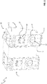
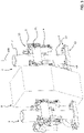
Figures 1-4 schematically show the switching apparatus of the invention; -
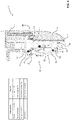
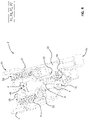
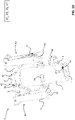
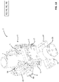
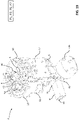
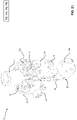
Figures 2-18 the structure and operation of an electric pole of the switching apparatus of the invention according to a possible embodiment; -
Figures 19-21 the structure and operation of an electric pole of the switching apparatus of the invention, according to another embodiment; -
Figure 22 schematically shows the switching apparatus of the invention, according to another embodiment; - Figure 24 schematically shows the switching apparatus of the invention, according to yet another embodiment.
- With reference to the cited figures, the present invention relates to a switching
apparatus 1 for electric grids. - The
switching apparatus 1 is particularly suitable for use in low-voltage DC electric grids and it will be described hereinafter with particular reference to these applications for the sake of brevity only, without intending to limit the scope of the invention in any way. - The
switching apparatus 1 may, in fact, be successfully used in electric systems of different type, such as low-voltage AC electric grids or medium-voltage AC or DC electric grids. - For the purpose of the present application, the term "low-voltage" (LV) relates to operating voltages lower than 1 kV AC and 1.5 kV DC whereas the term "medium-voltage" (MV) relates to operating voltages higher than 1 kV AC and 1.5 kV DC up to some tens of kV, e.g. up to 72 kV AC and 100 kV DC.
- Preferably, the
switching apparatus 1 is a circuit-breaker. However, in principle, it may be of different type, for example a contactor, a disconnector, or the like. - The
switching apparatus 1 comprises one or moreelectric poles 2, preferably two electric poles as shown infigures 1-4 or three electric poles as shown infigure 22 . - According to the invention, each
electric pole 2 comprises anouter casing 3 made of an electrically insulating material (e.g. a thermoplastic material) and defining an internal volume, in which a number of components of said electric pole are accommodated. - The
outer casing 3 conveniently extends along a corresponding mainlongitudinal axis 100, preferably with a parallelepiped-like shape, and it has opposite first end portion 35 (normally the bottom end portion) and second end portion 36 (normally the top end). - Preferably, the
outer casing 3 is made of multiple shells or parts that can be mutually joined with fixing means of known type, as shown infigure 5 . - Preferably, the
casing 3 of each electric pole is fixed to a main support structure (not shown) of theswitching apparatus 1 at itsfirst end portion 35. - Each
electric pole 2 comprises afirst pole terminal 16 and asecond pole terminal 17. - The first and
second pole terminals - Preferably, the
pole terminals outer casing 3 of the electric pole. - Preferably, the first and
second pole terminals first opening 37 and asecond opening 38 of theouter casing 3 respectively in a proximal position and a distal position relative to thelower end portion 35 of the outer casing. - According to the invention, each
electric pole 2 comprises a fixedcontact assembly 40 accommodated in the internal volume of said electric pole. - The fixed
contact assembly 40 comprises a fixedcontact member 4, which is electrically connected to thefirst pole terminal 16. - The fixed
contact member 4 is formed by an electrically conductive tubular element extending along thelongitudinal axis 100 of the electric pole. - The fixed
contact member 4 comprises opposite first and second ends 4A, 4B. At thefirst end 4A, the fixedcontact member 4 is fixed to theouter casing 3, in proximity of thefirst end portion 35 of this latter, and it is electrically connected to thefirst pole terminal 16. Thesecond end 4B of the fixedcontact member 4 is instead free-standing within the internal volume of the electric pole. - Preferably, the fixed
contact member 4 is formed by a hollow tubular element of electrically conductive material (e.g. copper), which may have a cylindrical shape (as shown in the cited figures) or a polyhedric shape. - Preferably, the fixed
contact assembly 40 comprises coupling means 41, 42 for fixing the fixedcontact member 4 to theouter casing 3 and electrically connecting the fixedcontact member 4 to thefirst pole terminal 16. - In the embodiments shown in the cited figures, the above-mentioned coupling means comprises a
first support element 41 of electrically insulating material. Thefirst support element 41 is formed by a tubular element (preferably including a longitudinal centring hole), which passes through the fixedcontact member 4 along thelongitudinal axis 100. To this aim, the first support element may have a cylindrical shape (as shown in the cited figures) or a polyhedric shape, in such a way to fit the fixedcontact member 4. - At the
first end 4A of the fixedcontact member 4, thefirst support element 41 is fixed to one or moresecond support elements 42 of electrically conductive material, which are arranged transversally relative to the fixedcontact member 4. Thesecond support elements 42 are in turn fixed to theouter casing 3 of the electric pole and to thefirst pole terminal 16. In this way, they support the fixedcontact member 4 and, at the same time, they electrically connect this latter to thefirst pole terminal 16. - According to the invention, each
electric pole 2 comprises at least amovable contact assembly 50 accommodated in the internal volume and hanging laterally relative to said fixedcontact member 4, preferably a long a circumference or polygon centred with thelongitudinal axis 100 and laying along a plane perpendicular to this latter. - Preferably, each
electric pole 2 comprises a plurality (preferably one or more pairs) ofmovable contact assemblies 50 equally spaced around the fixedcontact member 4. - In the cited figures, there are shown preferred embodiments of the invention, in which each
electric pole 2 comprises two pairs ofmovable contact assemblies 50 equally spaced around the fixedcontact member 4. Each pair ofmovable contact assemblies 50 is conveniently arranged at opposite sides of the fixedcontact member 4. - However, different arrangements of the movable contact assemblies are possible, according to the needs. For example, each
electric pole 2 may comprise two or threemovable contact assemblies 50 equally spaced around the fixedcontact member 4. Furthermore, in principle, eachelectric pole 2 may comprise even a singlemovable contact assembly 50. - According to the invention, each
movable contact assembly 50 comprises one or moremovable contact members 5, which are electrically connected to thesecond pole terminal 17. - According to some embodiments of the invention (
figures 1-18 ), eachmovable contact assembly 50 comprises a pair ofmovable contact members 5 movable in parallel around a same first rotation axis R1. - According to other embodiments of the invention (
figures 19-21 ), eachmovable contact assembly 50 comprises a singlemovable contact member 5 movable around a corresponding first rotation axis R1. - Each
movable contact member 5 is movable about a first rotation axis R1 and comprises acontact surface 5A intended to be coupled with or decoupled from acorresponding contact surface 4C of the fixed contact member. - In particular, each
movable contact member 5 is reversibly movable, about a first rotation axis R1, between a coupled position P1 (figures 6-10 ,19-20 ), at which thecontact surface 5A of saidmovable contact member 5 is coupled with acorresponding contact surface 4C of the fixedcontact member 4, and an uncoupled position P2 (figures 12-13 ,21 ), at which thecontact surface 5A of themovable contact member 5 is separated from thecorresponding contact surface 4A of the fixedcontact member 4. - When the
movable contact members 5 of eachelectric pole 2 are in a coupled position P1, an electric current can flow along said electric pole between thepole terminals - When the
movable contact members 5 of eachelectric pole 2 are in an uncoupled position P2, no electric current can flow along said electric pole. The switching apparatus is in an open condition. - A transition from a closed condition to an open condition forms an opening manoeuvre of the switching apparatus whereas a transition from an open condition to a closed condition forms a closing manoeuvre of the switching apparatus.
- According to the invention, each
movable contact assembly 50 comprises atleast trip mechanism 6 coupled to the one or moremovable contact members 5 of said movable contact assembly for actuating said one or more movable contact members. - In the cited figures, there are shown preferred embodiments of the invention, in which each
movable contact assembly 50 comprises atrip mechanism 6 for eachmovable contact member 5. However, different arrangements of the movable contact assemblies are possible, according to the needs. For example, eachmovable contact assembly 50 may comprise asingle trip mechanism 6 for actuating a pair ofmovable contact members 5 in parallel. - Each
trip mechanism 6 is adapted to actuate at least a correspondingmovable contact member 5 between the above-mentioned coupled and uncoupled positions P1, P2. - To this aim, each
trip mechanism 6 is reversibly movable between a first trip position P3 and a second trip position P4. - When it moves from the first trip position P3 to the second trip position P4 upon receiving an actuation force, each
trip mechanism 6 moves a correspondingmovable contact member 5 from the coupled position P1 to the uncoupled position P2 (figures 6-10 ,19-20 ). - When it moves from the second trip position P4 to the first trip position P3 upon receiving an actuation force, each
trip mechanism 6 moves a correspondingmovable contact member 5 from the uncoupled position P2 to the coupled position P1 (figures 12-13 ,21 ). - Preferably, each
movable contact assembly 50 comprises a supportingframe 51 to hold in position eachmovable contact member 5 and eachtrip mechanism 6 of said movable contact assembly. - Preferably, each supporting
frame 51 is arranged (for example as a U-shaped frame) in such a way to hold the one or moremovable contact members 5 andtrip mechanisms 6 in their operating positions and, at the same time, allow the above-described movements of these components. - According to an aspect of the invention, each
electric pole 2 comprises an internal supportingstructure 25 for holding themovable contact assemblies 50 in such a way that these latter are hung laterally relative to the fixedcontact member 4, around this latter. - The supporting
structure 25 is made of an electrically conductive material and is electrically connected to eachmovable contact member 5 and to thesecond pole terminal 17 through suitable electrical connections (partially shown infigures 7-8 ,13 ). - The supporting
frame 51 of eachmovable contact assembly 50 is fixed to a suitable corresponding portion of the supportingframe 25. - When its supporting
frame 51 is fixed to the supportingframe 25, eachmovable contact member 5 is conveniently oriented along a corresponding reference plane (not shown) belonging to a bundle of planes intersecting at thelongitudinal axis 100. - The supporting
structure 25 is fixed to theouter casing 3 though suitable fixing means (not shown), which may be of known type. In this way, the one or moremovable contact assemblies 50 are rigidly fixed to the contact frame. - According to the invention, each
electric pole 2 comprises anactuation member 7 accommodated in the internal volume of said electric pole. - The
actuation member 7 is formed by an electrically insulating hollow tubular element arranged coaxially and externally relative to the fixedcontact member 4, so that the fixedcontact member 4 passes through theactuation member 7, along thelongitudinal axis 100. - Conveniently, the
actuation member 7 may have a cylindrical shape (as shown in the cited figures) or a polyhedric shape, in such a way to fit the fixedcontact member 4. - The
actuation member 7 is coupled to the fixedcontact member 4, so that it can slidingly move along the fixedcontact member 4. - The
actuation member 7 is adapted to transmit an actuation force to eachtrip mechanism 6 of themovable contact assemblies 50. - To this aim, the actuation member is reversibly movable between a first actuation position P5 and a second actuation position P6 by sliding along the fixed
contact member 4. - When it moves between the above-mentioned first and second actuation positions P5, P6, the
actuation member 7 transiently couples (i.e. it does not couple in a permanent or stable manner) to eachtrip mechanism 6 to actuate said trip mechanism between the above-mentioned first and second trip positions P3, P4. - When it moves from the first actuation position P5 to the second actuation position P6, the
actuation member 7 transiently couples to eachtrip mechanism 6 and provides an actuation force to move saidtrip mechanism 6 from the first trip position P3 to the second trip position P4 (figures 6 ,7 ,17 ). - When it moves from the second actuation position P6 to the first actuation position P5, the
actuation member 7 transiently couples to eachtrip mechanism 6 and provides an actuation force to move saidtrip mechanism 6 from the second trip position P2 to the first trip position P3 (figures 12 ,13 ,19 ). - According to a particularly important aspect of the invention, an insulating
portion 70 of theactuation member 7 is interposed between thecontact surface 5A of eachmovable contact member 5 and thecorresponding contact surface 4A of the fixedcontact member 4, when theactuation member 7 is in the second actuation position P6 (figures 12 ,13 ,19 ). - Preferably, each
electric pole 2 comprises amotion transmission member 8 solidly coupled to theactuation member 7, more preferably in such a way to form a single piece with this latter. - Preferably, the
motion transmission member 8 is formed by an electrically insulating tubular element (which may have a cylindrical shape or a polyhedric shape and it may be optionally provided with one or more longitudinal holes) oriented along a transversal direction perpendicular to thelongitudinal axis 100 of the electric pole. - Preferably, the
motion transmission member 8 coupled, at afirst end 8A, to theactuation member 7, conveniently in a proximal position relative to thefirst end 4A of the fixedcontact member 4. - Preferably, the
transmission member 8 protrudes from theouter casing 3, more preferably at asecond end 8B, opposite to thefirst end 8A. - Conveniently, the
motion transmission member 8 passes through aslot 31 arranged at alateral wall 3A of theouter casing 3 and oriented along a direction parallel to thelongitudinal axis 100. Themotion transmission member 8 is adapted to transmit an actuation force to theactuation member 7, so that this latter can slide along the fixedcontact member 4 between the above-mentioned actuation positions P5, P6. - Being rigidly coupled to the
actuation member 7, themotion transmission member 8 moves along a motion direction D parallel to thelongitudinal axis 100, thereby sliding along theslot 31 of theouter casing 3. - According to an aspect of the invention, the
switching apparatus 1 comprises actuation means 9 for actuating theactuation member 7 of eachelectric pole 2. In this way, theactuation members 7, theoperating mechanisms 6 and movable contact members of all the electric poles operate simultaneously according to the needs. - Preferably, the actuation means 9 are coupled to the
motion transmission member 8 of eachelectric pole 2, in particular to thesecond end 8B of this latter. In this way, the actuation means 9 can actuate theactuation member 7 of each electric pole through the correspondingmotion transmission member 8. - In general, the actuation means 9 are of mechanical type or electromagnetic type.
- According to some embodiments of the invention (
figures 1-4 ), the actuation means 9 are according to a side-by-side configuration with theelectric poles 2. In these cases, theswitching apparatus 1 preferably comprises twoelectric poles 2 only. - In general, however, the
switching apparatus 1 may comprise even three or moreelectric poles 2 as shown infigure 22 . In these cases, theactuation member 7 of each electric pole, which is in a relatively distal positaion with respect to the actuation means 9, is conveniently actuated by a relatively complex motion transmission chain including amotion transmission member 8. According to other embodiments of the invention (figure 23 ), the actuation means 9 are arranged at the front side or the rear side of the switching apparatus. In these cases, theswitching apparatus 1 may conveniently comprise even a relatively high number of electric poles (e.g. three or four). - According to an aspect of the invention, each
trip mechanism 6 comprises a kinematic chain for transmitting an actuation force to a correspondingmovable contact member 5, upon actuation by theactuation member 7. - Such a kinematic chain conveniently comprises a
first lever 61 reversibly movable about a second rotation axis R2 (parallel to the first rotation axis of the movable contact member 5), in particular between a first rotation position P7 (figures 6-11 ,19-20 ) and a second rotation position P8 (figures 12-14 ,21 ). - The
first lever 61 is conveniently arranged in such a way to be actuated by theactuation member 7, when this latter moves between the first and second actuation positions P5, P6. - When it moves from the first actuation position P5 to the second actuation position P6, the
actuation member 7 transiently couples to thefirst lever 61 and actuates this latter to move it from the first rotation position P7 to the second rotation position P8. - When it moves from the second actuation position P6 to the first actuation position P5, the
actuation member 7 transiently couples to thefirst lever 61 and actuates this latter to move it from the second rotation position P8 to the first rotation position P1. - The above-mentioned kinematic chain comprises a
second lever 62 coupled to thefirst lever 61 and to themovable contact member 5. Thesecond lever 62 is conveniently arranged in such a way to transmit an actuation force to themovable contact member 5 to move this latter between the coupled and uncoupled positions P1, P2, when thefirst lever 61 is actuated by theactuation member 7. - In particular, the
second lever 62 is coupled to the first lever 61 (about a rotation axis R5 parallel to the rotation axes R1, R2) in such a way to form a first crack-slider mechanism transforming a rotation movement of thefirst lever 61 in a translation movement of thesecond lever 62. - Similarly, the
second lever 62 is coupled to the movable contact member 5 (about another rotation axis R6 parallel to the rotation axes R1, R2) in such a way to form a second crack-slider mechanism transforming a translation movement of thesecond lever 62 in a rotation movement of themovable contact member 5. - When the
first lever 61 moves from the first rotation position P7 to the second rotation position P8, thesecond lever 62 transmits an actuation force to themovable contact member 5 to move this latter from the coupled position P1 to the uncoupled position P2, - When the
first lever 61 moves from the second rotation position P8 to the first rotation position P1, thesecond lever 62 transmits an actuation force to themovable contact member 5 to move this latter from the uncoupled position P2 to the coupled position P1. - According to an aspect of the invention, each
trip mechanism 6 comprises trippingmeans 63 for providing an actuation force to move a correspondingmovable contact member 5 towards the coupled position P1 or towards the uncoupled position P2, when themovable contact member 5 moves past a deadlock position P0, while travelling between the coupled and uncoupled positions P1, P2. - While the
movable contact member 5 is travelling from the coupled position P1 towards the uncoupled position P2 upon the actuation force provided by the kinematic chain 61-62, the trippingmeans 63 provides an actuation force to trip themovable contact member 5 to the uncoupled position P2, as soon as themovable contact member 5 moves past a certain deadlock position P0. - While the
movable contact member 5 is travelling from the uncoupled position P2 towards the coupled position P1 upon the actuation force provided by the kinematic chain 61-62, the trippingmeans 63 provides an actuation force to trip themovable contact member 5 to the coupled position P1, as soon as themovable contact member 5 moves past the deadlock position P0. - Preferably (
figures 11 ,14 ), the trippingmeans 63 comprises aspring 631 coaxially arranged along a supportingpin 632 having opposite ends respectively coupled with themovable contact member 5 at a rotation axis R3 (parallel to the rotation axes R1, R2) and with the supportingframe 51 at another rotation axis R4 (parallel to the rotation axes R1, R2, R3). In this case, the above-mentioned deadlock position P0 can be defined as the rotation position of themovable contact member 5, in which the rotation axis R1 of themovable contact member 5 and the rotation axes R3, R4 of the opposite ends of the supportingpin 632 are aligned (figures 6 ,12 ). According to an aspect of the invention, theactuation member 7 comprises one ormore protrusions trip mechanism 6, more particularly thefirst lever 61 of each trip mechanism. - According to some embodiments of the invention (
figures 1-18 ), thefirst lever 61 of eachtrip mechanism 6 comprises afirst arm 611 and asecond arm 612 that are angularly spaced one from another along a reference plane parallel to thelongitudinal axis 100. - In this case, the
actuation member 7 comprises, for eachtrip mechanism 6, anactuation protrusion 70 for coupling with thefirst lever 61. - The
actuation protrusion 70 couples transiently to thefirst arm 611 of thefirst lever 61 to actuate this latter, when theactuation member 7 moves from the first actuation position P5 to the second actuation positions P6. In this case, the actuation force provided by theactuation member 7 moves thefirst lever 61 from the first rotation position P7 to the second rotation position P8. - The
same actuation protrusion 70 couples transiently to thefirst arm 611 of thefirst lever 61 to actuate this latter, when theactuation member 7 moves from the second actuation position P6 to the first actuation positions P8. In this case, the actuation force provided by theactuation member 7 moves thefirst lever 61 from the second rotation position P8 to the first rotation position P7. - According to other embodiments of the invention (
figures 19-21 ), thefirst lever 61 of eachtrip mechanism 6 comprises a single free-standing arm for coupling theactuation member 7, which may be variously shaped (e.g. T-shaped). - In this case, the
actuation member 7 comprises, for eachtrip mechanism 6, afirst actuation protrusion 71 and asecond actuation protrusion 72 for coupling with thefirst lever 61. - The first and
second protrusions longitudinal axis 100, respectively in a proximal position and in a distal position relative to thefirst end 4A of the fixed contact member 4 (or better thefirst end 35 of the outer casing 3). - The
first actuation protrusion 71 couples transiently to thefirst lever 61 to actuate this latter, when theactuation member 7 moves from the first actuation position P5 to the second actuation positions P6. In this case, the actuation force provided by theactuation member 7 moves thefirst lever 61 from the first rotation position P7 to the second rotation position P8. - The
second actuation protrusion 72 couples transiently to thefirst lever 61 to actuate this latter, when theactuation member 7 moves from the second actuation position P6 to the first actuation positions P8. In this case, the actuation force provided by theactuation member 7 moves thefirst lever 61 from the second rotation position P8 to the first rotation position P7. - According to an aspect of the invention, each
electric pole 2 comprises deformable covering means 32, 33, 34 for obstructing a portion of theslot 31 of the outer casing 3 (which is not occupied by the motion transmission member 8), when themotion transmission member 8 takes different positions or moves along said slot. - Conveniently, the above-mentioned covering means 32, 33, 34 are driven by the
motion transmission member 8, when this latter moves along theslot 31, upon actuation by the actuation means 9. - According to some embodiments of the invention (
figure 15-16 ), the above-mentioned covering means comprise abellow membrane 32, which is coupled to themotion transmission member 8 and to theouter casing 3. - Different portions of the
bellow membrane 32, which are arranged at opposite sides of themotion transmission member 8, are alternatively movable between an extended position and a folded position, upon a corresponding movement of themotion transmission member 8 along the slot 31 (motion direction D). When a portion of thefoldable membrane 32 is in an extended position, it obstructs a corresponding side of theslot 31. - According to other embodiments of the invention (
figure 17-18 ), the above-mentioned covering means comprise afirst plate 33, which has an end coupled to themotion transmission member 8 at a first side of this latter and the opposite end rotatably coupled to asupport pin 38, and asecond plate 34, which has an end coupled to themotion transmission member 8 and the opposite end rotatably coupled to thesupport pin 38. - The
plates slot 31 and a folded position, at which they are folded one on another, upon a corresponding movement D of themotion transmission member 8 along theslot 31. In this case, theslot 31 is obstructed by a third slidingplate 38A linearly movable along the slot 31 (direction D) and driven by themotion transmission member 8. Thesupport pin 38 conveniently slides along a suitable guidinggroove 39 obtained on an internal supportingwall 39A of theouter casing 3. - The operation of the
switching apparatus 1 is now described in more details. - The
switching apparatus 1 is supposed to be in a closed condition (figures 6-11 ,19-20 ). - In this situation, each
movable contact member 5 of each electric pole is in the coupled position P1 and it has itscontact surface 5A coupled to acorresponding contact surface 4C of the fixedcontact member 4. A current can therefore flow between thepole terminals - The
actuation member 7 of each electric pole is in the first actuation position P5 while eachtrip mechanism 6 of the electric pole is in the first trip position P3 with thefirst lever 61 in the first rotation position P7. - In order to carry out an opening manoeuvre, the actuation means 9 actuate the
actuation member 7 of each electric pole from the first actuation position P5 to the second actuation position P6. - While travelling towards the second actuation position P6 by sliding along the fixed
contact member 4, theactuation member 7 actuates eachtrip mechanism 6 and it causes this latter to trip from the first trip position P3 to the second trip position P4. - In particular, the
first lever 61 of eachtrip mechanism 6 is actuated by a correspondingprotrusion actuation member 7 and it moves from the first rotation position P7 to the second rotation position P8. - The
second lever 62 of eachtrip mechanism 6 transmits an actuation force to themovable contact member 5, which starts moving from the coupled position P1 to the uncoupled position P2. - While each
movable contact member 5 is travelling from the coupled position P1 towards the uncoupled position P2 upon the actuation force provided by the kinematic chain 61-62, as soon as themovable contact member 5 moves past a certain deadlock position P0, the tripping means 63 of eachtrip mechanism 6 provides an additional actuation force, which finally trips themovable contact member 5 to the uncoupled position P2. - The opening manoeuvre is thus completed (
figures 12-15 ,21 ). - It is evidenced that while each
movable contact member 5 is travelling towards the uncoupled position P2, a corresponding insulatingportion 7A of the actuation member 7 (which travels towards the second actuation position P6) interposes between thecontact surface 5A of themovable contact member 5 and thecorresponding contact surface 4C of the fixedcontact member 4, thereby favouring the quenching of possible electric arcs raising between the electric contacts under separation. - The
switching apparatus 1 is supposed to be in an open condition (figures 12-15 ,21 ).
In this situation, eachmovable contact member 5 of each electric pole is in the uncoupled position P2 and it has itscontact surface 5A separated acorresponding contact surface 4C of the fixedcontact member 4. No current can therefore flow between thepole terminals
Theactuation member 7 of each electric pole is in the second actuation position P6 while eachtrip mechanism 6 of the electric pole is in the second trip position P4 with thefirst lever 61 in the second rotation position P8. - In order to carry out a closing manoeuvre, the actuation means 9 actuate the
actuation member 7 of each electric pole from the second actuation position P6 to the first actuation position P5.
While travelling towards the first actuation position P5 by sliding along the fixedcontact member 4, theactuation member 7 actuates eachtrip mechanism 6 and it causes this latter to trip from the second trip position P4 to the first trip position P3.
In particular, thefirst lever 61 of eachtrip mechanism 6 is actuated by a correspondingprotrusion actuation member 7 and it moves from the second rotation position P8 to the first rotation position P7.
Thesecond lever 62 of eachtrip mechanism 6 transmits an actuation force to themovable contact member 5, which starts moving from the uncoupled position P2 to the coupled position P1.
While eachmovable contact member 5 is travelling from the uncoupled position P2 towards the coupled position P1 upon the actuation force provided by the kinematic chain 61-62, as soon as themovable contact member 5 moves past the deadlock position P0, the tripping means 63 of eachtrip mechanism 6 provides an additional actuation force, which finally trips themovable contact member 5 to the coupled position P1.
The closing manoeuvre is thus completed (figures 6-11 ,19-20 ). - The
switching apparatus 1, according to the invention, offers remarkable advantages over the prior art.
Thanks to the particular configuration of the breaking components (thefixed contact member 4, themovable contact members 5 and the actuating chain for moving each movable contact member), theswitching apparatus 1 shows an excellent switching efficiency and provides excellent performances in terms of interruption ratings during the opening manoeuvres.
Differently from traditional switching apparatuses, theswitching apparatus 1 can efficiently operate DC currents even when operating at relatively high voltages (e.g. above 1 kV). In particular, the interposition of insulatingportions 7A of theactuation member 7 between theelectric contacts
Theswitching apparatus 1 is therefore capable of operating at high current levels, thereby showing improved switching performances when short-circuit currents need to be interrupted. Theswitching apparatus 1 comprises electric poles with an optimized layout of the internal components, which allows limiting overall size and reducing manufacturing costs.
Theswitching apparatus 1 is thus characterised by a very compact structure and it is particularly simple and cheap to manufacture at industrial level.
Theswitching apparatus 1 has a simple and robust structure, which is particularly suitable for installation in a LV or MV electric grid.
Claims (15)
- A switching apparatus (1) for low or medium voltage electric power distribution grids,wherein said switching apparatus comprising one or more electric poles (2), wherein electric pole (2) comprises:- an outer casing (3) made of electrically insulating material and defining an internal volume of said electric pole;- a fixed contact assembly (40) accommodated in the internal volume of said electric pole and comprising a fixed contact member (4) formed by an electrically conductive tubular element extending along a longitudinal axis (100) of said electric pole;- at least a movable contact assembly (50) accommodated in the internal volume of said electric pole and hanging laterally relative to said fixed contact member (4),wherein each movable contact assembly (50) comprises at least a movable contact member (5), each movable contact member being reversibly movable, about a first rotation axis (R1), between a coupled position (P1), at which a first contact surface (5A) of said movable contact member (5) is coupled with a corresponding second contact surface (4C) of said fixed contact member (4), and an uncoupled position (P2), at which the first contact surface (5A) of said movable contact member (5) is separated from the second contact surface (4C) of said fixed contact member (4),wherein each movable contact assembly comprises at least a trip mechanism (6) coupled to at least a movable contact member (5), said trip mechanism being reversibly movable between a first trip position (P3) and a second trip position (P4), wherein said trip mechanism moves said movable contact member (5) from said coupled position (P1) to said uncoupled position (P2) when said trip mechanism moves from said first trip position (P3) to said second trip position (P4) upon receiving an actuation force,wherein said trip mechanism moves said movable contact member (5) from said uncoupled position (P2) to said coupled position (P1) when said trip mechanism moves from said second trip position (P4) to said first trip position (P3) upon receiving an actuation force;characterised in that each electric pole (2) comprises an actuation member (7) accommodated in the internal volume of said electric pole and formed by an electrically insulating hollow tubular element arranged coaxially and externally relative to said fixed contact member (4), so that said fixed contact member (4) passes through said actuation member along said longitudinal axis (100),wherein said actuation member (7) is slidingly movable along said fixed contact member (4),wherein said actuation member is reversibly movable between a first actuation position (P5) and a second actuation position (P6) by sliding along said fixed contact member (4), wherein said actuation member transiently couples to each trip mechanism (6) to actuate said trip mechanism between said first and second trip positions (P3, P4), when said actuation member moves between said first and second actuation positions (P5, P6).
- Switching apparatus, according to claim 1, characterised in that:- said actuation member (7) transiently couples to each trip mechanism (6) and provides an actuation force to move said trip mechanism (6) from said first trip position (P3) to said second trip position (P4), when said actuation member moves from said first actuation position (P5) to said second actuation position (P6);- said actuation member (7) transiently couples to each said trip mechanism (6) and provides an actuation force to move said trip mechanism (6) from said second trip position (P4) to said first trip position (P3), when said actuation member moves from said second actuation position (P6) to said first actuation position (P5).
- Switching apparatus, according to one or more of the previous claims, characterised in that an insulating portion (7A) of said actuation member (7) is interposed between a contact surface (5A) of each movable contact member (5) and a corresponding contact surface (4A) of said fixed contact member (4), when said actuation member is in said second actuation position (P6).
- Switching apparatus, according to one or more of the previous claims, characterised in that it comprises actuation means (9) for actuating the actuation member (7) of each electric pole (2).
- Switching apparatus, according to claim 4, characterised in that each electric pole (2) comprises a motion transmission member (8) coupled to said actuation means (9) and coupled to said actuation member (7) to transmit an actuation force to said actuation member.
- Switching apparatus, according to one or more of the previous claims, characterised in that each trip mechanism (6) comprises a kinematic chain including:- a first lever (61) reversibly movable about a second rotation axis (R2) and arranged in such a way to be actuated by said actuation member (7), when said actuation member moves between said first and second actuation positions (P5, P6);- a second lever (62) coupled to said first lever and to a movable contact member (5), said second lever transmitting an actuation force to said movable contact member (5) to move said movable contact member between said coupled and uncoupled positions (P1, P2), when said first lever (61) is actuated by said actuation member (7).
- Switching apparatus, according to claim 6, characterised in that said first lever (61) comprises a first arm (61) and a second arm (62) that are angularly spaced one from another along a reference plane parallel to said longitudinal axis (100),wherein said actuation member (7) comprises an actuation protrusion (70) for coupling with said first lever (61),wherein said actuation protrusion (70) transiently couples to said first arm (611) to actuate said first lever (61), when said actuation member (7) moves from said first actuation position (P5) to said second actuation position (P6),wherein said actuation protrusion (70) transiently couples to said second arm (612) to actuate said first lever (61), when said actuation member (7) moves from said second actuation position (P6) to said first actuation position (P5).
- Switching apparatus, according to claim 6, characterised in that said actuation member (7) comprises a first actuation protrusion (71) and a second actuation protrusion (72) for coupling with said first lever (61), said first and second protrusions being spaced one from another along said longitudinal axis (100),wherein said first actuation protrusion (71) transiently couples to said first arm (611) to actuate said first lever (61), when said actuation member (7) moves from said first actuation position (P5) to said second actuation position (P6),wherein said second actuation protrusion (72) transiently couples to said second arm (612) to actuate said first lever (61), when said actuation member (7) moves from said second actuation position (P6) to said first actuation position (P5).
- Switching apparatus, according to one or more of the previous claims, characterised in that each trip mechanism (6) comprises tripping means (63) providing an actuation force to trip said movable contact member (5) towards said coupled position (P1) or towards said uncoupled position (P2), when said movable contact member moves past a deadlock position (P0), while travelling between said coupled and uncoupled positions (P1, P2).
- Switching apparatus, according to one or more of the previous claims, characterised in that each electric pole (2) comprises a plurality of movable contact assemblies (50) equally spaced around said fixed contact member (4).
- Switching apparatus, according to one or more of the previous claims, characterised in that each movable contact assembly (50) comprises a pair of movable contact members (5) movable in parallel around a same first rotation axis (R1).
- Switching apparatus, according to one or more of the claims from 1 to 10, characterised in that each movable contact assembly (50) comprises a single movable contact member (5) movable around a corresponding first rotation axis (R1).
- Switching apparatus, according to one or more of the previous claims, characterised in that each movable contact assembly (50) comprises a trip mechanism (6) for each movable contact member (5).
- Switching apparatus, according to one or more of the previous claims, characterised in that each movable contact assembly (50) comprises a supporting frame (51) to hold in position each movable contact member (5) and each trip mechanism (6) of said movable contact assembly, said supporting frame being fixed to a supporting structure (25) fixed to said outer casing (3).
- Switching apparatus, according to claim 3, characterised in that said motion transmission member (8) passes through a slot (31) of said outer casing (3),
wherein said electric pole (2) comprises deformable covering means (32, 33, 34) driven by said motion transmission member (7) for obstructing a portion of said slot (31), which is not occupied by said motion transmission member.
Priority Applications (3)
| Application Number | Priority Date | Filing Date | Title |
|---|---|---|---|
| EP21185085.4A EP4120307B1 (en) | 2021-07-12 | 2021-07-12 | A switching apparatus for electric grids |
| US17/860,260 US12224144B2 (en) | 2021-07-12 | 2022-07-08 | Switching apparatus for electric grids |
| CN202210811466.4A CN115621059A (en) | 2021-07-12 | 2022-07-11 | Switching device for an electrical network |
Applications Claiming Priority (1)
| Application Number | Priority Date | Filing Date | Title |
|---|---|---|---|
| EP21185085.4A EP4120307B1 (en) | 2021-07-12 | 2021-07-12 | A switching apparatus for electric grids |
Publications (2)
| Publication Number | Publication Date |
|---|---|
| EP4120307A1 true EP4120307A1 (en) | 2023-01-18 |
| EP4120307B1 EP4120307B1 (en) | 2023-11-29 |
Family
ID=76890895
Family Applications (1)
| Application Number | Title | Priority Date | Filing Date |
|---|---|---|---|
| EP21185085.4A Active EP4120307B1 (en) | 2021-07-12 | 2021-07-12 | A switching apparatus for electric grids |
Country Status (3)
| Country | Link |
|---|---|
| US (1) | US12224144B2 (en) |
| EP (1) | EP4120307B1 (en) |
| CN (1) | CN115621059A (en) |
Citations (3)
| Publication number | Priority date | Publication date | Assignee | Title |
|---|---|---|---|---|
| US3129307A (en) * | 1960-04-13 | 1964-04-14 | Vargas Jose Munoz De | Device for accelerating the disconnection of electric switches and for extinguishing their arc |
| DE10064525A1 (en) * | 2000-12-22 | 2002-06-27 | Abb Patent Gmbh | MV switching device has parallel semiconductor switch across separation point conducting during opening movement of latter |
| EP3624159A1 (en) * | 2018-09-11 | 2020-03-18 | ABB Schweiz AG | A switching device |
Family Cites Families (8)
| Publication number | Priority date | Publication date | Assignee | Title |
|---|---|---|---|---|
| US2388251A (en) * | 1944-06-22 | 1945-11-06 | Rockrite Processes Inc | Tube reducing mill |
| US4118608A (en) * | 1976-12-02 | 1978-10-03 | I-T-E Imperial Corporation | Trip indicator |
| ATA252692A (en) | 1992-12-21 | 1997-11-15 | Elin Energieversorgung | CIRCUIT ARRANGEMENT FOR A LOAD SELECTOR |
| AT410612B (en) | 2001-04-20 | 2003-06-25 | Reinhausen Maschf Scheubeck | LAST VOTER |
| EP2523203B1 (en) | 2011-05-10 | 2019-07-03 | ABB Schweiz AG | Switching device and related switchgear |
| ES2700835T3 (en) | 2015-07-07 | 2019-02-19 | Abb Technology Ag | Switching device |
| EP4030457B1 (en) * | 2021-01-14 | 2023-10-25 | ABB Schweiz AG | A medium voltage switching apparatus |
| EP4276870B1 (en) * | 2022-05-12 | 2026-04-22 | ABB Schweiz AG | A medium voltage switching apparatus |
-
2021
- 2021-07-12 EP EP21185085.4A patent/EP4120307B1/en active Active
-
2022
- 2022-07-08 US US17/860,260 patent/US12224144B2/en active Active
- 2022-07-11 CN CN202210811466.4A patent/CN115621059A/en active Pending
Patent Citations (3)
| Publication number | Priority date | Publication date | Assignee | Title |
|---|---|---|---|---|
| US3129307A (en) * | 1960-04-13 | 1964-04-14 | Vargas Jose Munoz De | Device for accelerating the disconnection of electric switches and for extinguishing their arc |
| DE10064525A1 (en) * | 2000-12-22 | 2002-06-27 | Abb Patent Gmbh | MV switching device has parallel semiconductor switch across separation point conducting during opening movement of latter |
| EP3624159A1 (en) * | 2018-09-11 | 2020-03-18 | ABB Schweiz AG | A switching device |
Also Published As
| Publication number | Publication date |
|---|---|
| CN115621059A (en) | 2023-01-17 |
| US20230010157A1 (en) | 2023-01-12 |
| EP4120307B1 (en) | 2023-11-29 |
| US12224144B2 (en) | 2025-02-11 |
Similar Documents
| Publication | Publication Date | Title |
|---|---|---|
| US8264306B2 (en) | Movable contactor assembly for current limiting type molded case circuit breaker | |
| US8411418B2 (en) | Vacuum insulated switchgear | |
| CN108281320B (en) | 3-way disconnector and earthing switch for gas-insulated switchgear | |
| CN110890242B (en) | Switching device | |
| EP4030457B1 (en) | A medium voltage switching apparatus | |
| CN102473547B (en) | Gas-insulated high-voltage switching system | |
| US12444559B2 (en) | Medium voltage switching apparatus | |
| EP4276872B1 (en) | A medium voltage switching apparatus | |
| CN110890241B (en) | Switching device | |
| US20200357585A1 (en) | Electric switch limiter pole and dc electric switch comprising such a limiter pole | |
| EP4120307B1 (en) | A switching apparatus for electric grids | |
| CN104733224A (en) | Switching apparatus for electrical power sytems | |
| US12387890B2 (en) | Medium voltage switching apparatus | |
| EP4283645B1 (en) | A medium voltage switching apparatus | |
| EP4277059A1 (en) | Switchgear equipment for electric power distribution grids | |
| EP4276869A1 (en) | A medium voltage switching apparatus | |
| CN115210837A (en) | Switching device for medium voltage | |
| US20230368992A1 (en) | Medium voltage switching apparatus | |
| EP4641601A1 (en) | A switching apparatus for electrical systems | |
| US20250372324A1 (en) | Medium voltage switching apparatus | |
| US20260066198A1 (en) | Low and medium voltage electrical pole | |
| US20030117246A1 (en) | Power switch with a double breaking contact arrangement | |
| EP4030455A1 (en) | A medium voltage switching apparatus |
Legal Events
| Date | Code | Title | Description |
|---|---|---|---|
| PUAI | Public reference made under article 153(3) epc to a published international application that has entered the european phase |
Free format text: ORIGINAL CODE: 0009012 |
|
| STAA | Information on the status of an ep patent application or granted ep patent |
Free format text: STATUS: THE APPLICATION HAS BEEN PUBLISHED |
|
| AK | Designated contracting states |
Kind code of ref document: A1 Designated state(s): AL AT BE BG CH CY CZ DE DK EE ES FI FR GB GR HR HU IE IS IT LI LT LU LV MC MK MT NL NO PL PT RO RS SE SI SK SM TR |
|
| STAA | Information on the status of an ep patent application or granted ep patent |
Free format text: STATUS: REQUEST FOR EXAMINATION WAS MADE |
|
| 17P | Request for examination filed |
Effective date: 20230427 |
|
| RBV | Designated contracting states (corrected) |
Designated state(s): AL AT BE BG CH CY CZ DE DK EE ES FI FR GB GR HR HU IE IS IT LI LT LU LV MC MK MT NL NO PL PT RO RS SE SI SK SM TR |
|
| GRAP | Despatch of communication of intention to grant a patent |
Free format text: ORIGINAL CODE: EPIDOSNIGR1 |
|
| STAA | Information on the status of an ep patent application or granted ep patent |
Free format text: STATUS: GRANT OF PATENT IS INTENDED |
|
| RIC1 | Information provided on ipc code assigned before grant |
Ipc: H01H 33/06 20060101AFI20230804BHEP |
|
| INTG | Intention to grant announced |
Effective date: 20230823 |
|
| GRAS | Grant fee paid |
Free format text: ORIGINAL CODE: EPIDOSNIGR3 |
|
| GRAA | (expected) grant |
Free format text: ORIGINAL CODE: 0009210 |
|
| STAA | Information on the status of an ep patent application or granted ep patent |
Free format text: STATUS: THE PATENT HAS BEEN GRANTED |
|
| AK | Designated contracting states |
Kind code of ref document: B1 Designated state(s): AL AT BE BG CH CY CZ DE DK EE ES FI FR GB GR HR HU IE IS IT LI LT LU LV MC MK MT NL NO PL PT RO RS SE SI SK SM TR |
|
| REG | Reference to a national code |
Ref country code: GB Ref legal event code: FG4D |
|
| REG | Reference to a national code |
Ref country code: CH Ref legal event code: EP |
|
| REG | Reference to a national code |
Ref country code: DE Ref legal event code: R096 Ref document number: 602021007217 Country of ref document: DE |
|
| REG | Reference to a national code |
Ref country code: IE Ref legal event code: FG4D |
|
| REG | Reference to a national code |
Ref country code: LT Ref legal event code: MG9D |
|
| REG | Reference to a national code |
Ref country code: NL Ref legal event code: MP Effective date: 20231129 |
|
| PG25 | Lapsed in a contracting state [announced via postgrant information from national office to epo] |
Ref country code: GR Free format text: LAPSE BECAUSE OF FAILURE TO SUBMIT A TRANSLATION OF THE DESCRIPTION OR TO PAY THE FEE WITHIN THE PRESCRIBED TIME-LIMIT Effective date: 20240301 |
|
| PG25 | Lapsed in a contracting state [announced via postgrant information from national office to epo] |
Ref country code: IS Free format text: LAPSE BECAUSE OF FAILURE TO SUBMIT A TRANSLATION OF THE DESCRIPTION OR TO PAY THE FEE WITHIN THE PRESCRIBED TIME-LIMIT Effective date: 20240329 |
|
| PG25 | Lapsed in a contracting state [announced via postgrant information from national office to epo] |
Ref country code: LT Free format text: LAPSE BECAUSE OF FAILURE TO SUBMIT A TRANSLATION OF THE DESCRIPTION OR TO PAY THE FEE WITHIN THE PRESCRIBED TIME-LIMIT Effective date: 20231129 |
|
| PG25 | Lapsed in a contracting state [announced via postgrant information from national office to epo] |
Ref country code: ES Free format text: LAPSE BECAUSE OF FAILURE TO SUBMIT A TRANSLATION OF THE DESCRIPTION OR TO PAY THE FEE WITHIN THE PRESCRIBED TIME-LIMIT Effective date: 20231129 |
|
| PG25 | Lapsed in a contracting state [announced via postgrant information from national office to epo] |
Ref country code: LT Free format text: LAPSE BECAUSE OF FAILURE TO SUBMIT A TRANSLATION OF THE DESCRIPTION OR TO PAY THE FEE WITHIN THE PRESCRIBED TIME-LIMIT Effective date: 20231129 Ref country code: IS Free format text: LAPSE BECAUSE OF FAILURE TO SUBMIT A TRANSLATION OF THE DESCRIPTION OR TO PAY THE FEE WITHIN THE PRESCRIBED TIME-LIMIT Effective date: 20240329 Ref country code: GR Free format text: LAPSE BECAUSE OF FAILURE TO SUBMIT A TRANSLATION OF THE DESCRIPTION OR TO PAY THE FEE WITHIN THE PRESCRIBED TIME-LIMIT Effective date: 20240301 Ref country code: ES Free format text: LAPSE BECAUSE OF FAILURE TO SUBMIT A TRANSLATION OF THE DESCRIPTION OR TO PAY THE FEE WITHIN THE PRESCRIBED TIME-LIMIT Effective date: 20231129 Ref country code: BG Free format text: LAPSE BECAUSE OF FAILURE TO SUBMIT A TRANSLATION OF THE DESCRIPTION OR TO PAY THE FEE WITHIN THE PRESCRIBED TIME-LIMIT Effective date: 20240229 |
|
| REG | Reference to a national code |
Ref country code: AT Ref legal event code: MK05 Ref document number: 1637012 Country of ref document: AT Kind code of ref document: T Effective date: 20231129 |
|
| PG25 | Lapsed in a contracting state [announced via postgrant information from national office to epo] |
Ref country code: NL Free format text: LAPSE BECAUSE OF FAILURE TO SUBMIT A TRANSLATION OF THE DESCRIPTION OR TO PAY THE FEE WITHIN THE PRESCRIBED TIME-LIMIT Effective date: 20231129 |
|
| PG25 | Lapsed in a contracting state [announced via postgrant information from national office to epo] |
Ref country code: SE Free format text: LAPSE BECAUSE OF FAILURE TO SUBMIT A TRANSLATION OF THE DESCRIPTION OR TO PAY THE FEE WITHIN THE PRESCRIBED TIME-LIMIT Effective date: 20231129 Ref country code: RS Free format text: LAPSE BECAUSE OF FAILURE TO SUBMIT A TRANSLATION OF THE DESCRIPTION OR TO PAY THE FEE WITHIN THE PRESCRIBED TIME-LIMIT Effective date: 20231129 Ref country code: PL Free format text: LAPSE BECAUSE OF FAILURE TO SUBMIT A TRANSLATION OF THE DESCRIPTION OR TO PAY THE FEE WITHIN THE PRESCRIBED TIME-LIMIT Effective date: 20231129 Ref country code: NO Free format text: LAPSE BECAUSE OF FAILURE TO SUBMIT A TRANSLATION OF THE DESCRIPTION OR TO PAY THE FEE WITHIN THE PRESCRIBED TIME-LIMIT Effective date: 20240229 Ref country code: NL Free format text: LAPSE BECAUSE OF FAILURE TO SUBMIT A TRANSLATION OF THE DESCRIPTION OR TO PAY THE FEE WITHIN THE PRESCRIBED TIME-LIMIT Effective date: 20231129 Ref country code: LV Free format text: LAPSE BECAUSE OF FAILURE TO SUBMIT A TRANSLATION OF THE DESCRIPTION OR TO PAY THE FEE WITHIN THE PRESCRIBED TIME-LIMIT Effective date: 20231129 Ref country code: HR Free format text: LAPSE BECAUSE OF FAILURE TO SUBMIT A TRANSLATION OF THE DESCRIPTION OR TO PAY THE FEE WITHIN THE PRESCRIBED TIME-LIMIT Effective date: 20231129 |
|
| PG25 | Lapsed in a contracting state [announced via postgrant information from national office to epo] |
Ref country code: DK Free format text: LAPSE BECAUSE OF FAILURE TO SUBMIT A TRANSLATION OF THE DESCRIPTION OR TO PAY THE FEE WITHIN THE PRESCRIBED TIME-LIMIT Effective date: 20231129 |
|
| PG25 | Lapsed in a contracting state [announced via postgrant information from national office to epo] |
Ref country code: CZ Free format text: LAPSE BECAUSE OF FAILURE TO SUBMIT A TRANSLATION OF THE DESCRIPTION OR TO PAY THE FEE WITHIN THE PRESCRIBED TIME-LIMIT Effective date: 20231129 Ref country code: AT Free format text: LAPSE BECAUSE OF FAILURE TO SUBMIT A TRANSLATION OF THE DESCRIPTION OR TO PAY THE FEE WITHIN THE PRESCRIBED TIME-LIMIT Effective date: 20231129 |
|
| PG25 | Lapsed in a contracting state [announced via postgrant information from national office to epo] |
Ref country code: SK Free format text: LAPSE BECAUSE OF FAILURE TO SUBMIT A TRANSLATION OF THE DESCRIPTION OR TO PAY THE FEE WITHIN THE PRESCRIBED TIME-LIMIT Effective date: 20231129 |
|
| PG25 | Lapsed in a contracting state [announced via postgrant information from national office to epo] |
Ref country code: SM Free format text: LAPSE BECAUSE OF FAILURE TO SUBMIT A TRANSLATION OF THE DESCRIPTION OR TO PAY THE FEE WITHIN THE PRESCRIBED TIME-LIMIT Effective date: 20231129 Ref country code: SK Free format text: LAPSE BECAUSE OF FAILURE TO SUBMIT A TRANSLATION OF THE DESCRIPTION OR TO PAY THE FEE WITHIN THE PRESCRIBED TIME-LIMIT Effective date: 20231129 Ref country code: RO Free format text: LAPSE BECAUSE OF FAILURE TO SUBMIT A TRANSLATION OF THE DESCRIPTION OR TO PAY THE FEE WITHIN THE PRESCRIBED TIME-LIMIT Effective date: 20231129 Ref country code: EE Free format text: LAPSE BECAUSE OF FAILURE TO SUBMIT A TRANSLATION OF THE DESCRIPTION OR TO PAY THE FEE WITHIN THE PRESCRIBED TIME-LIMIT Effective date: 20231129 Ref country code: DK Free format text: LAPSE BECAUSE OF FAILURE TO SUBMIT A TRANSLATION OF THE DESCRIPTION OR TO PAY THE FEE WITHIN THE PRESCRIBED TIME-LIMIT Effective date: 20231129 Ref country code: CZ Free format text: LAPSE BECAUSE OF FAILURE TO SUBMIT A TRANSLATION OF THE DESCRIPTION OR TO PAY THE FEE WITHIN THE PRESCRIBED TIME-LIMIT Effective date: 20231129 Ref country code: AT Free format text: LAPSE BECAUSE OF FAILURE TO SUBMIT A TRANSLATION OF THE DESCRIPTION OR TO PAY THE FEE WITHIN THE PRESCRIBED TIME-LIMIT Effective date: 20231129 |
|
| PG25 | Lapsed in a contracting state [announced via postgrant information from national office to epo] |
Ref country code: PT Free format text: LAPSE BECAUSE OF FAILURE TO SUBMIT A TRANSLATION OF THE DESCRIPTION OR TO PAY THE FEE WITHIN THE PRESCRIBED TIME-LIMIT Effective date: 20240401 |
|
| PG25 | Lapsed in a contracting state [announced via postgrant information from national office to epo] |
Ref country code: PT Free format text: LAPSE BECAUSE OF FAILURE TO SUBMIT A TRANSLATION OF THE DESCRIPTION OR TO PAY THE FEE WITHIN THE PRESCRIBED TIME-LIMIT Effective date: 20240401 |
|
| REG | Reference to a national code |
Ref country code: DE Ref legal event code: R097 Ref document number: 602021007217 Country of ref document: DE |
|
| PLBE | No opposition filed within time limit |
Free format text: ORIGINAL CODE: 0009261 |
|
| STAA | Information on the status of an ep patent application or granted ep patent |
Free format text: STATUS: NO OPPOSITION FILED WITHIN TIME LIMIT |
|
| PG25 | Lapsed in a contracting state [announced via postgrant information from national office to epo] |
Ref country code: SI Free format text: LAPSE BECAUSE OF FAILURE TO SUBMIT A TRANSLATION OF THE DESCRIPTION OR TO PAY THE FEE WITHIN THE PRESCRIBED TIME-LIMIT Effective date: 20231129 |
|
| PG25 | Lapsed in a contracting state [announced via postgrant information from national office to epo] |
Ref country code: SI Free format text: LAPSE BECAUSE OF FAILURE TO SUBMIT A TRANSLATION OF THE DESCRIPTION OR TO PAY THE FEE WITHIN THE PRESCRIBED TIME-LIMIT Effective date: 20231129 |
|
| 26N | No opposition filed |
Effective date: 20240830 |
|
| PG25 | Lapsed in a contracting state [announced via postgrant information from national office to epo] |
Ref country code: MC Free format text: LAPSE BECAUSE OF FAILURE TO SUBMIT A TRANSLATION OF THE DESCRIPTION OR TO PAY THE FEE WITHIN THE PRESCRIBED TIME-LIMIT Effective date: 20231129 |
|
| REG | Reference to a national code |
Ref country code: CH Ref legal event code: PL |
|
| PG25 | Lapsed in a contracting state [announced via postgrant information from national office to epo] |
Ref country code: LU Free format text: LAPSE BECAUSE OF NON-PAYMENT OF DUE FEES Effective date: 20240712 |
|
| PG25 | Lapsed in a contracting state [announced via postgrant information from national office to epo] |
Ref country code: LU Free format text: LAPSE BECAUSE OF NON-PAYMENT OF DUE FEES Effective date: 20240712 |
|
| PG25 | Lapsed in a contracting state [announced via postgrant information from national office to epo] |
Ref country code: CH Free format text: LAPSE BECAUSE OF NON-PAYMENT OF DUE FEES Effective date: 20240731 Ref country code: BE Free format text: LAPSE BECAUSE OF NON-PAYMENT OF DUE FEES Effective date: 20240731 |
|
| REG | Reference to a national code |
Ref country code: BE Ref legal event code: MM Effective date: 20240731 |
|
| PG25 | Lapsed in a contracting state [announced via postgrant information from national office to epo] |
Ref country code: IE Free format text: LAPSE BECAUSE OF NON-PAYMENT OF DUE FEES Effective date: 20240712 |
|
| PG25 | Lapsed in a contracting state [announced via postgrant information from national office to epo] |
Ref country code: FI Free format text: LAPSE BECAUSE OF FAILURE TO SUBMIT A TRANSLATION OF THE DESCRIPTION OR TO PAY THE FEE WITHIN THE PRESCRIBED TIME-LIMIT Effective date: 20231129 |
|
| PGFP | Annual fee paid to national office [announced via postgrant information from national office to epo] |
Ref country code: DE Payment date: 20250722 Year of fee payment: 5 |
|
| PGFP | Annual fee paid to national office [announced via postgrant information from national office to epo] |
Ref country code: IT Payment date: 20250724 Year of fee payment: 5 |
|
| PGFP | Annual fee paid to national office [announced via postgrant information from national office to epo] |
Ref country code: GB Payment date: 20250724 Year of fee payment: 5 |
|
| PGFP | Annual fee paid to national office [announced via postgrant information from national office to epo] |
Ref country code: FR Payment date: 20250725 Year of fee payment: 5 |
|
| PG25 | Lapsed in a contracting state [announced via postgrant information from national office to epo] |
Ref country code: CY Free format text: LAPSE BECAUSE OF FAILURE TO SUBMIT A TRANSLATION OF THE DESCRIPTION OR TO PAY THE FEE WITHIN THE PRESCRIBED TIME-LIMIT; INVALID AB INITIO Effective date: 20210712 |
|
| PG25 | Lapsed in a contracting state [announced via postgrant information from national office to epo] |
Ref country code: HU Free format text: LAPSE BECAUSE OF FAILURE TO SUBMIT A TRANSLATION OF THE DESCRIPTION OR TO PAY THE FEE WITHIN THE PRESCRIBED TIME-LIMIT; INVALID AB INITIO Effective date: 20210712 |