EP4120294A1 - Magnetization device and magnetizing method - Google Patents
Magnetization device and magnetizing method Download PDFInfo
- Publication number
- EP4120294A1 EP4120294A1 EP21768102.2A EP21768102A EP4120294A1 EP 4120294 A1 EP4120294 A1 EP 4120294A1 EP 21768102 A EP21768102 A EP 21768102A EP 4120294 A1 EP4120294 A1 EP 4120294A1
- Authority
- EP
- European Patent Office
- Prior art keywords
- annular portion
- magnetizing apparatus
- magnetizing
- magnet
- marker
- Prior art date
- Legal status (The legal status is an assumption and is not a legal conclusion. Google has not performed a legal analysis and makes no representation as to the accuracy of the status listed.)
- Pending
Links
Images







Classifications
-
- H—ELECTRICITY
- H01—ELECTRIC ELEMENTS
- H01F—MAGNETS; INDUCTANCES; TRANSFORMERS; SELECTION OF MATERIALS FOR THEIR MAGNETIC PROPERTIES
- H01F13/00—Apparatus or processes for magnetising or demagnetising
-
- H—ELECTRICITY
- H01—ELECTRIC ELEMENTS
- H01F—MAGNETS; INDUCTANCES; TRANSFORMERS; SELECTION OF MATERIALS FOR THEIR MAGNETIC PROPERTIES
- H01F13/00—Apparatus or processes for magnetising or demagnetising
- H01F13/003—Methods and devices for magnetising permanent magnets
-
- H—ELECTRICITY
- H01—ELECTRIC ELEMENTS
- H01F—MAGNETS; INDUCTANCES; TRANSFORMERS; SELECTION OF MATERIALS FOR THEIR MAGNETIC PROPERTIES
- H01F7/00—Magnets
- H01F7/02—Permanent magnets [PM]
- H01F7/0273—Magnetic circuits with PM for magnetic field generation
-
- H—ELECTRICITY
- H01—ELECTRIC ELEMENTS
- H01F—MAGNETS; INDUCTANCES; TRANSFORMERS; SELECTION OF MATERIALS FOR THEIR MAGNETIC PROPERTIES
- H01F7/00—Magnets
- H01F7/02—Permanent magnets [PM]
- H01F7/0273—Magnetic circuits with PM for magnetic field generation
- H01F7/0294—Detection, inspection, magnetic treatment
-
- G—PHYSICS
- G01—MEASURING; TESTING
- G01N—INVESTIGATING OR ANALYSING MATERIALS BY DETERMINING THEIR CHEMICAL OR PHYSICAL PROPERTIES
- G01N27/00—Investigating or analysing materials by the use of electric, electrochemical, or magnetic means
- G01N27/72—Investigating or analysing materials by the use of electric, electrochemical, or magnetic means by investigating magnetic variables
- G01N27/82—Investigating or analysing materials by the use of electric, electrochemical, or magnetic means by investigating magnetic variables for investigating the presence of flaws
- G01N27/83—Investigating or analysing materials by the use of electric, electrochemical, or magnetic means by investigating magnetic variables for investigating the presence of flaws by investigating stray magnetic fields
- G01N27/84—Investigating or analysing materials by the use of electric, electrochemical, or magnetic means by investigating magnetic variables for investigating the presence of flaws by investigating stray magnetic fields by applying magnetic powder or magnetic ink
-
- H—ELECTRICITY
- H01—ELECTRIC ELEMENTS
- H01F—MAGNETS; INDUCTANCES; TRANSFORMERS; SELECTION OF MATERIALS FOR THEIR MAGNETIC PROPERTIES
- H01F7/00—Magnets
- H01F7/02—Permanent magnets [PM]
- H01F7/0205—Magnetic circuits with PM in general
- H01F7/021—Construction of PM
Definitions
- the present disclosure relates to a magnetizing apparatus and a magnetizing method.
- Magnetic flaw detection methods detect anomalies based on the principle that when a magnetized object has an anomaly such as wear or damage, leakage magnetic flux is generated at the anomalous area.
- magnetic powder flaw detection method magnetic powder is sprinkled on the magnetized object, and the resulting magnetic powder pattern is evaluated.
- magnetic flux leakage flaw detection method flux leakage is detected by a sensor. For example, see Patent Literature (PTL) 1.
- the object is preferably magnetized as uniformly as possible.
- a magnetization device with an annular magnet may be used. By inserting the object into the annular magnet, the object can be uniformly magnetized in the peripheral direction.
- the magnetic flaw detection method may be applied while the object is being magnetized by the magnetizing device, or the magnetic flaw detection method may be applied after the object is magnetized by the magnetizing device and is provided with residual magnetization, that is, after the object is magnetized.
- the present disclosure aims to provide a magnetizing apparatus and a magnetizing method that enable accurate and rapid detection of anomalies for objects of various shapes.
- a magnetizing apparatus includes a circular or non-circular openable and closeable annular portion formed by a magnet, wherein the annular portion includes a lock mechanism configured to hold the annular portion in a closed state.
- the magnetizing apparatus can be attached to the object by opening and closing the annular portion to place the object inside the annular portion and locking the lock mechanism to hold the annular portion in the closed state. Therefore, the object can be magnetized substantially uniformly in the peripheral direction of the annular portion by the magnet forming the annular portion.
- anomalies can be detected accurately and rapidly using magnetic flaw detection methods such as the magnetic powder flaw detection method and magnetic flux leakage flaw detection method.
- the magnetizing apparatus can be made available for another object by releasing the lock mechanism and detaching the magnetizing apparatus from the object.
- the peripheral direction of the annular portion refers to the direction that encircles the central axis of the annular portion when the annular portion is closed.
- the magnetizing apparatus further includes a marker holder configured to hold a marker.
- a marker holder configured to hold a marker.
- the magnetizing apparatus can be moved in the axial direction of the annular portion relative to the object to magnetize the object and simultaneously apply a marking to the magnetized area. It is therefore easy to apply a marking that enables identification of the magnetized area.
- the marker is, for example, configured by a pen.
- the axial direction of the annular portion refers to the direction along the central axis of the annular portion when the annular portion is closed.
- the magnet has different polarities in an axial direction of the annular portion. According to this configuration, the object can be magnetized efficiently.
- the magnet includes a plurality of portions interconnected in a peripheral direction of the annular portion. According to this configuration, the annular portion can easily be configured.
- the annular portion includes a hinge rotatably connecting portions of the magnet that are adjacent in the peripheral direction of the annular portion. According to this configuration, the rotation of the hinge enables a stable opening and closing operation of the annular portion.
- the hinge is a torque hinge with a predetermined rotational resistance. According to this configuration, the rotational resistance of the torque hinge can suppress the momentum, due to the repulsive force of the magnet, of the annular portion upon opening when the lock mechanism is released. This configuration thus enhances safety.
- the lock mechanism is configured by a toggle latch provided at both peripheral ends of the annular portion. According to this configuration, the lock mechanism can be locked by engaging an engaged portion of the toggle latch body, provided at one peripheral end of the annular portion, with an engagement portion of the toggle latch, provided at the other peripheral end of the annular portion, and the lock mechanism can be released by disengaging the toggle latch. The lock mechanism can therefore be locked and unlocked by a simple operation.
- the annular portion includes a sliding plate that forms an inner peripheral surface of the annular portion.
- the object can be easily magnetized by sliding the magnetizing apparatus via the sliding plate in the axial direction of the annular portion relative to the object while the magnetizing apparatus is attached to the object.
- the sliding plate reduces the sliding resistance between the magnetizing apparatus and the object.
- the marker holder is configured so that the marker is detachable. According to this configuration, the marker can be replaced. The marker can thereby be replaced with a new marker or with a marker of a different thickness, color, or the like.
- the marker holder presses the marker toward the radial inner side of the annular portion. According to this configuration, the marker can be more reliably pressed against the object to apply a marking to the object while the magnetizing apparatus is attached to the object.
- the radial direction refers to the direction along a line orthogonal to the central axis of the annular portion when the annular portion is closed.
- the marker holder holds the marker rotatably, or movably in the radial direction, toward the radial inner side of the annular portion. According to this configuration, the marker can be more reliably pressed against the object to apply a marking to the object while the magnetizing apparatus is attached to the object.
- the marker holder includes a first holder member supported by the annular portion, a second holder member held by the first holder member slidably along the radial direction of the annular portion, a fixing member that fixes the marker to the second holder member, and a forcing member that forces the second holder member toward the radial inner side of the annular portion.
- the marker can be held movably along the radial direction toward the radial inner side of the annular portion by a simple structure.
- the magnet extends over the entire periphery of the annular portion when the annular portion is closed. According to this configuration, the object can be magnetized more uniformly.
- the annular portion is formed by a connecting member that connects the plurality of portions of the magnet to each other. According to this configuration, the annular portion can more easily be configured.
- the connecting member includes the hinge. According to this configuration, the annular portion can more easily be configured.
- the connecting member covers each portion of the magnet. According to this configuration, the magnet can be protected by the connecting member.
- the magnetizing apparatus includes a handle. According to this configuration, the magnetizing apparatus can be easily moved by grasping the handle.
- the handle is provided at two locations on either side of the hinge in the peripheral direction of the annular portion. According to this configuration, the annular portion can be easily opened and closed by grasping the handles.
- the handle is provided on the connecting member. According to this configuration, the handle can easily be configured.
- a magnetizing method is a magnetizing method for magnetizing an object using the magnetizing apparatus, the magnetizing method including an attaching step of attaching the magnetizing apparatus on the object by opening and closing the annular portion to place the object inside the annular portion and holding the annular portion in a closed state with the lock mechanism, a moving step of moving the magnetizing apparatus relative to the object in an axial direction of the annular portion while the magnetizing apparatus is attached to the object, and a detaching step, after the moving step, of releasing the lock mechanism to detach the magnetizing apparatus from the object.
- the magnetizing apparatus can be attached to the object by the attaching step even when the object has irregularly shaped portions at both ends.
- the moving step enables the object to be magnetized uniformly in the peripheral direction of the annular portion.
- the detaching step enables the magnetizing apparatus to be made available for another object.
- the magnetizing apparatus includes a marker holder, and the magnetizing method further includes a marking step of applying a marking to the object, by performing the moving step, with a marker held by the marker holder.
- the marking step enables simultaneous magnetization of the object and application of a marking to the magnetized area. It is therefore easy to apply a marking that enables identification of the magnetized area.
- a magnetizing apparatus and a magnetizing method that enable accurate and rapid detection of anomalies for objects of various shapes can be provided.
- a magnetizing apparatus 1 includes a circular, openable and closable annular portion 3 formed by a magnet 2.
- the annular portion 3 includes a lock mechanism 4 that holds the annular portion 3 in a closed state.
- the annular portion 3 in the present embodiment is circular to correspond to a cylindrical pipe 11 as the object of magnetization, described below.
- the annular portion 3 may, however, also have a non-circular shape.
- the annular portion 3 may have an annular shape forming an H-shape or an I-shape to correspond to H-shaped steel or I-shaped steel as the object of magnetization.
- the axial direction in the context of the annular portion 3 or the magnet 2 refers to the direction along the central axis O of the annular portion 3 when the annular portion 3 is closed.
- the peripheral direction in the context of the annular portion 3 or the magnet 2 refers to the direction encircling the central axis O of the annular portion 3 when the annular portion 3 is closed.
- the radial direction in the context of the annular portion 3 or the magnet 2 refers to the direction along a line orthogonal to the central axis O of the annular portion 3 when the annular portion 3 is closed.
- the magnet 2 is formed by two semi-cylindrical portions 2a.
- the magnet 2 extends over the entire periphery in the peripheral direction of the annular portion 3 when the annular portion 3 is closed.
- one peripheral end face 2b of one portion 2a of the magnet 2 contacts one peripheral end face 2b of the other portion 2a of the magnet 2
- the other peripheral end face 2b of one portion 2a of the magnet 2 contacts the other peripheral end face 2b of the other portion 2a of the magnet 2.
- the magnet 2 has different polarities in the axial direction of the annular portion 3. That is, one axial end face 2c of the magnet 2 is the N pole, and the other axial end face 2c is the S pole.
- the magnet 2 is a permanent magnet.
- the magnet 2 is, for example, a neodymium magnet or a ferrite magnet.
- the annular portion 3 is formed by a connecting member 5 that interconnects the two portions 2a of the magnet 2.
- the annular portion 3 is formed by the magnet 2 and the connecting member 5.
- the connecting member 5 covers each portion 2a of the magnet 2.
- the connecting member 5 includes a hinge 6 that rotatably connects the two portions 2a of the magnet 2.
- the hinge 6 is a single-axis hinge that rotates around only one rotation axis P parallel to the central axis O of the annular portion 3.
- the hinge 6 includes an end 6a that is provided integrally with one portion 2a of the magnet 2 and an end 6a that is provided integrally with the other portion 2a of the magnet 2.
- the hinge 6 is provided at the radial outer end of the annular portion 3.
- the hinge 6 is a torque hinge having a predetermined rotational resistance.
- the connecting member 5 includes a sliding plate 7 that forms the inner peripheral surface of the annular portion 3.
- the sliding plate 7 is formed by two semi-cylindrical portions 7a.
- One portion 7a of the sliding plate 7 covers the inner peripheral surface of one portion 2a of the magnet 2, and the other portion 7a covers the inner peripheral surface of the other portion 2a of the magnet 2.
- Each portion 7a of the sliding plate 7 is formed of a synthetic resin material.
- the connecting member 5 includes handles 8 respectively provided at two locations on either side of the hinge 6 in the peripheral direction of the annular portion 3.
- One handle 8 is provided integrally with one portion 2a of the magnet 2, and the other handle 8 is provided integrally with the other portion 2a of the magnet 2.
- Both of the two handles 8 are provided at one axial end 3a of the annular portion 3.
- Each handle 8 is formed by a pair of rod-shaped ends 8a extending parallel to the central axis O of the annular portion 3 and a rod-shaped intermediate portion 8b connecting the pair of ends 8a.
- the two intermediate portions 8b face each other in the radial direction of the annular portion 3 and extend parallel to each other.
- the hinge 6, the sliding plate 7, and the two handles 8 are connected to a cover member 9.
- the connecting member 5 is formed by the hinge 6, the sliding plate 7, the two handles 8, and the cover member 9.
- the cover member 9 is formed by a portion 9a covering one portion 2a of the magnet 2 and a portion 9a covering the other portion 2a of the magnet 2.
- Each portion 9a of the cover member 9 includes a radial outer end 9b facing the outer peripheral surface of the magnet 2, one axial end 9c facing one axial end face 2c of the magnet 2, and another axial end 9c facing the other axial end face 2c of the magnet 2.
- Each portion 9a of the cover member 9 is formed by a plurality of members that are fixed to each other.
- the plurality of members is formed of a metallic material such as steel.
- the fixing means for the plurality of members is, for example, fastening means such as screws, or welding.
- One end 6a of the hinge 6 is fixed to the radial outer end 9b of one portion 9a of the cover member 9, and the other end 6a of the hinge 6 is fixed to the radial outer end 9b of the other portion 9a of the cover member 9.
- the fixing means is, for example, fastening means such as screws, or welding.
- Each end 6a of the hinge 6 is, for example, formed of a metallic material such as steel.
- One portion 7a of the sliding plate 7 is fixed to the pair of axial ends 9c of one portion 9a of the cover member 9 by swaging, and the other portion 7a of the sliding plate 7 is fixed to the pair of axial ends 9c of the other portion 9a of the cover member 9 by swaging.
- the pair of ends 8a of one handle 8 is fixed to one axial end 9c of one portion 9a of the cover member 9, and the pair of ends 8a of the other handle 8 is fixed to one axial end 9c of the other portion 9a of the cover member 9.
- the fixing means is, for example, fastening means such as screws, or welding.
- Each handle 8 is, for example, formed of a metallic material such as steel or a synthetic resin.
- the lock mechanism 4 is configured by a toggle latch 10 provided at both peripheral ends of the annular portion 3.
- the toggle latch 10 is formed by an engagement portion 10a provided at one peripheral end of the annular portion 3 and a toggle latch body 10b provided at the other peripheral end of the annular portion 3.
- the toggle latch body 10b includes an engaged portion 10c that is engaged with the engagement portion 10a.
- the toggle latch body 10b includes an operation lever 10d that releases the engagement between the engagement portion 10a and the engaged portion 10c by rotating towards the radial outer side of the annular portion 3 about a first rotation axis Q1.
- the operation lever 10d is axially supported by the radial outer end 9b of one portion 9a of the cover member 9 in a rotatable manner about the first rotation axis Q1.
- the toggle latch body 10b includes an engaged member 10e that is axially supported by the operation lever 10d in a rotatable manner about a second rotation axis Q2 parallel to the first rotation axis Q1.
- the engaged member 10e includes the engaged portion 10c.
- the engagement portion 10a of the toggle latch 10 is provided on an engagement member 10f fixed to the radial outer end 9b of the other portion 9a of the cover member 9.
- the fixing means is, for example, fastening means such as screws, or welding.
- the operation lever 10d, the engaged member 10e, and the engagement member 10f are, for example, formed of a metallic material such as steel.
- the magnetizing apparatus 1 can, for example, be used to achieve magnetization of the pipe 11 as a magnetic object, such as a ferromagnetic material, and provide the pipe 11 with residual magnetization, i.e., to magnetize the pipe 11.
- a magnetizing method according to the present embodiment to magnetize the pipe 11 using the magnetizing apparatus 1 includes an attaching step, a moving step, and a detaching step.
- the pipe 11 has flanges 11a as irregularly shaped portions at both ends in the axial direction.
- the pipe 11 has a circular cross-sectional shape and extends in a straight line in the axial direction.
- the pipe 11 has an outside diameter of, for example, 2 to 4 inches.
- the pipe 11 is, for example, installed in a plant, bridge, or other structure.
- the pipe 11 is placed inside the annular portion 3 by opening and closing the annular portion 3 (see FIG. 6 ), and the magnetizing apparatus 1 is attached to the pipe 11 by holding the annular portion 3 in a closed state with the lock mechanism 4 (see FIG. 7 ).
- the attaching step thus enables the magnetizing apparatus 1 to be attached to the pipe 11 that has irregularly shaped portions.
- the hinge 6 achieves a stable opening and closing operation of the annular portion 3.
- the lock mechanism 4 is locked by the engaged portion 10c of the toggle latch body 10b being engaged with the engagement portion 10a of the toggle latch 10.
- the portion of the pipe 11 located on the radial inner side of the magnet 2 is uniformly magnetized in the peripheral direction by the magnet 2.
- the magnet 2 since the magnet 2 has different polarities in the axial direction of the annular portion 3, the pipe 11 can be magnetized efficiently.
- the magnetizing apparatus 1 is moved relative to the pipe 11 in the axial direction of the annular portion 3 while the magnetizing apparatus 1 is attached to the pipe 11 (see FIG. 8 ).
- the annular portion 3 moves in a straight line in the axial direction of the pipe 11.
- the pipe 11 is magnetized in the moving range of the annular portion 3.
- the operator can easily move the annular portion 3 along the pipe 11 by grasping one or both of the two handles 8.
- the annular portion 3 is moved during the moving step toward the side at which the handles 8 are not provided, as illustrated in FIG. 8 .
- the attaching step may be performed so that the annular portion 3 can be moved toward the side at which the handles 8 are provided in the moving step.
- the annular portion 3 including the sliding plate 7 the sliding resistance between the magnetizing apparatus 1 and the pipe 11 is reduced to enable easy movement of the magnetizing apparatus 1 and also suppress scratching of the pipe 11.
- the magnetizing apparatus 1 is detached from the pipe 11 by releasing the lock mechanism 4 after the moving step (not illustrated). At this time, the worker can easily release the lock mechanism 4 by operating the operation lever 10d of the toggle latch body 10b.
- the lock mechanism 4 is released, the annular portion 3 opens due to the repulsive force of the magnet 2.
- the hinge 6 is a torque hinge, the momentum of the opening of the annular portion 3 is suppressed, thereby ensuring safety.
- the detaching step enables the magnetizing apparatus 1 to be made available for another object.
- detection means using a magnetic flaw detection method such as a magnetic powder flaw detection method or a magnetic flux leakage flaw detection method can be applied to the magnetized portion of the pipe 11 to detect abnormalities in the pipe 11 accurately and quickly.
- a magnetic flaw detection method such as a magnetic powder flaw detection method or a magnetic flux leakage flaw detection method
- FIGS. 9 and 10 A second embodiment of the present disclosure is illustrated next with reference to FIGS. 9 and 10 .
- the magnetizing apparatus 1 includes a marker holder 13 that detachably holds a marker 12.
- the marker holder 13 forces the marker 12 toward the radial inner side of the annular portion 3.
- the marker holder 13 holds the marker 12 rotatably toward the radial inner side of the annular portion 3.
- the marker holder 13 is axially supported by one axial end 9c of the cover member 9 in a rotatable manner about a rotation axis R.
- the rotation axis R extends in a direction perpendicular to both the radial and axial directions of the annular portion 3.
- the marker 12 is a pen.
- the marker holder 13 includes an inner peripheral surface 13a that can be attached to and detached from the outer peripheral surface of the marker 12 and is centered on an axis S.
- the marker 12 is disposed concentrically with the axis S by being held in the marker holder 13.
- the marker holder 13 is forced from a state in which the axis S is inclined relative to the axial outer side of the annular portion 3 toward the radial inner side of the annular portion 3 (the state illustrated by a solid line in FIG. 9 ) toward a state in which the axis S extends along the radial direction of the annular portion 3 (the state illustrated by a dashed double dotted line in FIG. 9 ).
- the forcing means is, for example, a spring.
- the pipe 11 can be magnetized by the same method as in the first embodiment. Also, according to the magnetizing apparatus 1 of the present embodiment, by performance of the moving step, a marking 14 can be applied to the pipe 11 by the marker 12 held in the marker holder 13. In other words, as illustrated in FIG. 9 , by the magnetizing apparatus 1 being moved along the pipe 11, the marker 12 can be moved along the pipe 11 together with the annular portion 3 while a pen tip 12a of the marker 12 is pressed against the outer peripheral surface of the pipe 11 by the marker holder 13. As a result, a marking 14 corresponding to the magnetized area of the pipe 11 in the axial direction is applied, as illustrated in FIG. 10 .
- the magnetized portion of the pipe 11 can be easily identified during application of detection means using a magnetic flaw detection method such as a magnetic powder flaw detection method or a magnetic flux leakage flaw detection method.
- a magnetic flaw detection method such as a magnetic powder flaw detection method or a magnetic flux leakage flaw detection method.
- the abnormality detection apparatus 15 can accurately be installed at the magnetized portion of the pipe 11, thus enabling accurate detection of anomalies using a magnetic flux leakage flaw detection method.
- FIGS. 11 to 15 A third embodiment of the present disclosure is illustrated next with reference to FIGS. 11 to 15 .
- the magnetizing apparatus 1 includes a marker holder 13 that detachably holds a marker 12.
- the marker holder 13 forces the marker 12 toward the radial inner side of the annular portion 3.
- the marker holder 13 holds the marker 12 movably in the radial direction toward the radial inner side of the annular portion 3.
- the marker holder 13 includes a first holder member 13b, a second holder member 13c, a fixing member 13d, and two tension springs 13e.
- the fixing member 13d is configured by a pressing member 13f and two fastening members 13g.
- the marker 12 is a pen.
- the first holder member 13b is supported by one axial end 9c of the cover member 9 of the annular portion 3.
- the second holder member 13c is fitted onto the first holder member 13b slidably along the radial direction.
- the first holder member 13b and the second holder member 13c are connected by two tension springs 13e. Therefore, the second holder member 13c is forced towards the radial inner side by these tension springs 13e.
- the tension springs 13e are arranged on either side of the annular portion 3 in the peripheral direction with respect to the marker 12.
- the second holder member 13c includes a pressure portion 13h that pushes a back end 12c of a torso 12b of the marker 12 (the opposite end from the pen tip 12a) toward the radial inner direction of the annular portion 3.
- the marker 12 is fixed to the second holder member 13c by the fixing member 13d.
- the pressing member 13f of the fixing member 13d includes a recess 13i, into which the torso 12b of the marker 12 is inserted, and insertion holes 13j located on either side of the recess 13i in the peripheral direction of the annular portion 3.
- a fastening member 13g is passed in the axial direction through each of the insertion holes 13j, and by the fastening members 13g being fastened to the second holder member 13c, the torso 12b of the marker 12 is clamped in the axial direction of the annular portion 3 by the pressing member 13f and the second holder member 13c.
- the first holder member 13b includes a base 13k, which is a flat plate perpendicular to the axial direction and supported by one axial end 9c of the cover member 9, and two side plates 131 that are located on either side of the torso 12b of the marker 12 in the peripheral direction of the annular portion 3 and are perpendicular to the base 13k. Between each of the side plates 131 and the base 13k, a slit 13m extending along the radial direction and opening to the radial outer side is formed.
- the second holder member 13c includes a moveable plate 13n, which is a flat plate parallel to the base 13k of the first holder member 13b, and the pressure portion 13h, which is a flat plate perpendicular to the moveable plate 13n.
- the moveable plate 13n includes slits 13o that respectively engage the slits 13m of the first holder member 13b. Each slit 13o extends along the radial direction and opens toward the radial inner side. By the meshing of the slits 13m and the slits 13o, the second holder member 13c can slide along the radial direction against the first holder member 13b.
- the moveable plate 13n includes fastening holes 13p into which the respective fastening members 13g are fastened.
- the two tension springs 13e connect the base 13k of the first holder member 13b and the moveable plate 13n of the second holder member 13c at either side, in the peripheral direction of the annular portion 3, of the two slits 13m and the two slits 13o.
- the marker holder 13 of the present embodiment includes the first holder member 13b supported by the annular portion 3, the second holder member 13c held by the first holder member 13b slidably along the radial direction of the annular portion 3, the fixing member 13d that fixes the marker 12 to the second holder 13c, and the two tension springs 13e as a forcing member that forces the second holder member 13c towards the radial inner side of the annular portion 3.
- the pipe 11 can be magnetized by the same method as in the second embodiment.
- a marking 14 can be applied to the pipe 11 by the marker 12 held in the marker holder 13.
- the marker 12 can be moved along the pipe 11 together with the annular portion 3 while the pen tip 12a of the marker 12 is pressed against the outer peripheral surface of the pipe 11 by the marker holder 13.
- a marking 14 corresponding to the magnetized area of the pipe 11 in the axial direction is applied, as in the second embodiment. Therefore, the magnetized portion of the pipe 11 can be easily identified during application of detection means using a magnetic flaw detection method.
- the marker holder 13 of the present embodiment can be modified in various ways.
- the marker holder 13 of the present embodiment may be configured to hold the marker 12 movably in the radial direction toward the radial inner side of the annular portion 3.
- the marker holder 13 of the present embodiment includes the first holder member 13b, the second holder member 13c, the fixing member 13d, and the forcing member (for example, the tension springs 13e)
- the marker holder 13 it suffices for the marker holder 13 to include the first holder member 13b supported by the annular portion 3, the second holder member 13c held by the first holder member 13b slidably along the radial direction of the annular portion 3, the fixing member 13d that fixes the marker 12 to the second holder 13c, and a forcing member that forces the second holder member 13c towards the radial inner side of the annular portion 3.
- the magnetizing apparatus 1 prefferably includes the circular or non-circular openable and closeable annular portion 3 formed by the magnet 2, and for the annular portion 3 to include the lock mechanism 4 configured to hold the annular portion 3 in a closed state.
- Each portion 2a of the magnet 2 is not limited to a semi-cylindrical shape.
- the magnet 2 is not limited to being formed by two portions 2a and may, for example, be formed by three or more portions.
- the magnet 2 is not limited to extending over the entire periphery in the peripheral direction of the annular portion 3 when the annular portion 3 is closed.
- the magnet 2 is not limited to having different polarities in the axial direction of the annular portion 3 and may, for example, have different polarities in the radial direction of the annular portion 3.
- the magnet 2 is not limited to being a permanent magnet and may be an electromagnet.
- the annular portion 3 is not limited to being formed by the connecting member 5.
- the connecting member 5 is not limited to covering each portion 2a of the magnet 2.
- the connecting member 5 may include two or more hinges 6 to rotatably connect the portions 2a of the magnet 2 that are adjacent to each other in the peripheral direction of the annular portion 3.
- the hinge 6 is not limited to a torque hinge.
- the hinge 6 is not limited to a single-axis hinge.
- the hinge 6 is not limited to being provided at the radial outer end of the annular portion 3.
- the annular portion 3 is not limited to including the hinge 6.
- the annular portion 3 may be formed from a deformable, soft material magnet 2.
- the connecting member 5 is not limited to including the sliding plate 7.
- Each portion 7a of the sliding plate 7 is not limited to a semi-cylindrical shape.
- the sliding plate 7 is not limited to being formed by two portions 2a and may, for example, be formed by three or more portions 7a to match the number of portions 2a of the magnet 2.
- Each portion 7a of the sliding plate 7 is not limited to being formed of a synthetic resin material.
- the connecting member 5 is not limited to including the handles 8.
- the handles 8 are not limited to being provided respectively at two locations on either side of the hinge 6 in the peripheral direction of the annular portion 3.
- the two handles 8 are both not limited to being provided at one axial end 3a of the annular portion 3.
- the handles 8 are not limited to being formed by the pair of ends 8a and the intermediate portion 8b.
- the connecting member 5 is not limited to including the cover member 9.
- the cover member 9 is not limited to being formed by two portions 9a and may, for example, be formed by three or more portions 9a to match the number of portions 2a of the magnet 2.
- Each portion 9a of the cover member 9 is not limited to including the radial outer end 9b facing the outer peripheral surface of the magnet 2, one axial end 9c facing one axial end face 2c of the magnet 2, and another axial end 9c facing the other axial end face 2c of the magnet 2.
- Each portion 9a of the cover member 9 is not limited to being formed by a plurality of members.
- the plurality of members configuring the portions 9a of the cover member 9 are not limited to being formed of a metallic material.
- the portions 9a of the cover member 9 are not limited to fixing the portions 7a of the sliding plate 7 by swaging.
- the lock mechanism 4 is not limited to being configured by the toggle latch 10.
- the lock mechanism 4 may be configured by fastening means such as a screw that detachably connects the peripheral ends of the annular portion 3.
- the toggle latch 10 is not limited to being provided at the peripheral ends of the annular portion 3.
- the object to be magnetized by the magnetizing apparatus 1 is not limited to the pipe 11.
- the object may, for example, be a column, beam, or the like in a plant, bridge, or other structure.
- the object may, for example, be structural material such as H-shaped steel or I-shaped steel.
- the pipe 11 is not limited to having a circular cross-sectional shape.
- the pipe 11 is not limited to extension in a straight line in the axial direction.
- the pipe 11 may include a corner that bends to form an angle such as a right angle.
- the magnetizing apparatus 1 is not limited to being configured for detachment after magnetization of the object to enable application of detection means using a magnetic flaw detection method.
- the magnetizing apparatus 1 may be configured so that detection means using a magnetic flaw detection method can be applied while the magnetizing apparatus 1 is still attached to the object.
- the magnetizing apparatus 1 may be used to demagnetize a magnetized object.
- the marker holder 13 is not limited to being attachable to and detachable from the marker 12.
- the marker holder 13 is not limited to forcing the marker 12 toward the radial inner side of the annular portion 3.
- the marker holder 13 is not limited to being axially supported by one axial end 9c of the cover member 9.
- the marker 12 is not limited to being a pen.
- the magnetizing apparatus 1 may include a plurality of marker holders 13 aligned in the peripheral direction of the annular portion 3.
- a plurality of abnormality detection apparatuses 15 may be installed in correspondence with a plurality of markings 14 applied using the plurality of marker holders 13.
Landscapes
- Engineering & Computer Science (AREA)
- Power Engineering (AREA)
- Physics & Mathematics (AREA)
- Electromagnetism (AREA)
- Investigating Or Analyzing Materials By The Use Of Magnetic Means (AREA)
- Soft Magnetic Materials (AREA)
- Manufacturing Cores, Coils, And Magnets (AREA)
Abstract
Description
- The present application claims priority to
Japanese Patent Application No. 2020-44810 filed on March 13, 2020 - The present disclosure relates to a magnetizing apparatus and a magnetizing method.
- Technology is known for detecting anomalies in magnetic objects using magnetic flaw detection methods such as a magnetic powder flaw detection method and a magnetic flux leakage flaw detection method. Magnetic flaw detection methods detect anomalies based on the principle that when a magnetized object has an anomaly such as wear or damage, leakage magnetic flux is generated at the anomalous area. In the magnetic powder flaw detection method, magnetic powder is sprinkled on the magnetized object, and the resulting magnetic powder pattern is evaluated. In the magnetic flux leakage flaw detection method, flux leakage is detected by a sensor. For example, see Patent Literature (PTL) 1.
- PTL 1:
US2015/0330946 A1 - In order to accurately and quickly detect anomalies in an object by a magnetic flaw detection method, the object is preferably magnetized as uniformly as possible. For this purpose, for example, a magnetization device with an annular magnet may be used. By inserting the object into the annular magnet, the object can be uniformly magnetized in the peripheral direction. In this case, the magnetic flaw detection method may be applied while the object is being magnetized by the magnetizing device, or the magnetic flaw detection method may be applied after the object is magnetized by the magnetizing device and is provided with residual magnetization, that is, after the object is magnetized.
- However, some pipes, columns, beams, and various other objects in plants, bridges, and other structures have irregularly shaped portions that expand or branch at both ends. It may not be possible to insert objects with irregularly shaped portions at both ends into an annular magnet. Even if an object does not have irregularly shaped portions at both ends, the object may be elongated, for example, making it difficult to place the annular magnet at locations such as the longitudinal center of the object.
- The present disclosure aims to provide a magnetizing apparatus and a magnetizing method that enable accurate and rapid detection of anomalies for objects of various shapes.
- A magnetizing apparatus according to some embodiments includes a circular or non-circular openable and closeable annular portion formed by a magnet, wherein the annular portion includes a lock mechanism configured to hold the annular portion in a closed state. According to this configuration, even if the object has irregularly shaped portions at both ends, the magnetizing apparatus can be attached to the object by opening and closing the annular portion to place the object inside the annular portion and locking the lock mechanism to hold the annular portion in the closed state. Therefore, the object can be magnetized substantially uniformly in the peripheral direction of the annular portion by the magnet forming the annular portion. As a result, anomalies can be detected accurately and rapidly using magnetic flaw detection methods such as the magnetic powder flaw detection method and magnetic flux leakage flaw detection method. Furthermore, according to this configuration, the magnetizing apparatus can be made available for another object by releasing the lock mechanism and detaching the magnetizing apparatus from the object. The peripheral direction of the annular portion refers to the direction that encircles the central axis of the annular portion when the annular portion is closed.
- In an embodiment, the magnetizing apparatus further includes a marker holder configured to hold a marker. According to this configuration, while the magnetizing apparatus is attached to the object and the marker holder is holding the marker, the magnetizing apparatus can be moved in the axial direction of the annular portion relative to the object to magnetize the object and simultaneously apply a marking to the magnetized area. It is therefore easy to apply a marking that enables identification of the magnetized area. The marker is, for example, configured by a pen. The axial direction of the annular portion refers to the direction along the central axis of the annular portion when the annular portion is closed.
- In an embodiment, the magnet has different polarities in an axial direction of the annular portion. According to this configuration, the object can be magnetized efficiently.
- In an embodiment, the magnet includes a plurality of portions interconnected in a peripheral direction of the annular portion. According to this configuration, the annular portion can easily be configured.
- In an embodiment, the annular portion includes a hinge rotatably connecting portions of the magnet that are adjacent in the peripheral direction of the annular portion. According to this configuration, the rotation of the hinge enables a stable opening and closing operation of the annular portion.
- In an embodiment, the hinge is a torque hinge with a predetermined rotational resistance. According to this configuration, the rotational resistance of the torque hinge can suppress the momentum, due to the repulsive force of the magnet, of the annular portion upon opening when the lock mechanism is released. This configuration thus enhances safety.
- In an embodiment, the lock mechanism is configured by a toggle latch provided at both peripheral ends of the annular portion. According to this configuration, the lock mechanism can be locked by engaging an engaged portion of the toggle latch body, provided at one peripheral end of the annular portion, with an engagement portion of the toggle latch, provided at the other peripheral end of the annular portion, and the lock mechanism can be released by disengaging the toggle latch. The lock mechanism can therefore be locked and unlocked by a simple operation.
- In an embodiment, the annular portion includes a sliding plate that forms an inner peripheral surface of the annular portion. According to this configuration, the object can be easily magnetized by sliding the magnetizing apparatus via the sliding plate in the axial direction of the annular portion relative to the object while the magnetizing apparatus is attached to the object. In other words, the sliding plate reduces the sliding resistance between the magnetizing apparatus and the object.
- In an embodiment, the marker holder is configured so that the marker is detachable. According to this configuration, the marker can be replaced. The marker can thereby be replaced with a new marker or with a marker of a different thickness, color, or the like.
- In an embodiment, the marker holder presses the marker toward the radial inner side of the annular portion. According to this configuration, the marker can be more reliably pressed against the object to apply a marking to the object while the magnetizing apparatus is attached to the object. The radial direction refers to the direction along a line orthogonal to the central axis of the annular portion when the annular portion is closed.
- In an embodiment, the marker holder holds the marker rotatably, or movably in the radial direction, toward the radial inner side of the annular portion. According to this configuration, the marker can be more reliably pressed against the object to apply a marking to the object while the magnetizing apparatus is attached to the object.
- In an embodiment, the marker holder includes a first holder member supported by the annular portion, a second holder member held by the first holder member slidably along the radial direction of the annular portion, a fixing member that fixes the marker to the second holder member, and a forcing member that forces the second holder member toward the radial inner side of the annular portion. According to this configuration, the marker can be held movably along the radial direction toward the radial inner side of the annular portion by a simple structure.
- In an embodiment, the magnet extends over the entire periphery of the annular portion when the annular portion is closed. According to this configuration, the object can be magnetized more uniformly.
- In an embodiment, the annular portion is formed by a connecting member that connects the plurality of portions of the magnet to each other. According to this configuration, the annular portion can more easily be configured.
- In an embodiment, the connecting member includes the hinge. According to this configuration, the annular portion can more easily be configured.
- In an embodiment, the connecting member covers each portion of the magnet. According to this configuration, the magnet can be protected by the connecting member.
- In an embodiment, the magnetizing apparatus includes a handle. According to this configuration, the magnetizing apparatus can be easily moved by grasping the handle.
- In an embodiment, the handle is provided at two locations on either side of the hinge in the peripheral direction of the annular portion. According to this configuration, the annular portion can be easily opened and closed by grasping the handles.
- In an embodiment, the handle is provided on the connecting member. According to this configuration, the handle can easily be configured.
- A magnetizing method according to some embodiments is a magnetizing method for magnetizing an object using the magnetizing apparatus, the magnetizing method including an attaching step of attaching the magnetizing apparatus on the object by opening and closing the annular portion to place the object inside the annular portion and holding the annular portion in a closed state with the lock mechanism, a moving step of moving the magnetizing apparatus relative to the object in an axial direction of the annular portion while the magnetizing apparatus is attached to the object, and a detaching step, after the moving step, of releasing the lock mechanism to detach the magnetizing apparatus from the object. According to this configuration, the magnetizing apparatus can be attached to the object by the attaching step even when the object has irregularly shaped portions at both ends. Furthermore, the moving step enables the object to be magnetized uniformly in the peripheral direction of the annular portion. The detaching step enables the magnetizing apparatus to be made available for another object.
- In an embodiment, the magnetizing apparatus includes a marker holder, and the magnetizing method further includes a marking step of applying a marking to the object, by performing the moving step, with a marker held by the marker holder. According to this configuration, the marking step enables simultaneous magnetization of the object and application of a marking to the magnetized area. It is therefore easy to apply a marking that enables identification of the magnetized area.
- According to the present disclosure, a magnetizing apparatus and a magnetizing method that enable accurate and rapid detection of anomalies for objects of various shapes can be provided.
- In the accompanying drawings:
-
FIG. 1 is a perspective view illustrating a magnetizing apparatus, according to a first embodiment, with an annular portion in an open state; -
FIG. 2 is a perspective view illustrating the magnetizing apparatus inFIG. 1 with the annular portion in a closed state; -
FIG. 3 is a plan view illustrating the magnetizing apparatus inFIG. 1 with the annular portion in a closed state; -
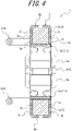
FIG. 4 is a cross-sectional view along the A-A line inFIG. 3 ; -
FIG. 5 is a perspective view illustrating a magnet of the magnetizing apparatus in the state illustrated inFIG. 2 ; -
FIG. 6 illustrates a state in which the annular portion of the magnetizing apparatus illustrated inFIG. 1 is opened and clamps a pipe; -
FIG. 7 is a diagram illustrating a state in which the annular portion is closed from the state illustrated inFIG. 6 and a lock mechanism is locked; -
FIG. 8 is a diagram illustrating a state in which the magnetizing apparatus is moved along the pipe from the state illustrated inFIG. 7 ; -
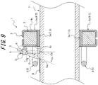
FIG. 9 is a diagram illustrating a state in which a magnetizing apparatus according to a second embodiment is moved along a pipe; -
FIG. 10 is a diagram illustrating a state in which a sensor is installed on a pipe magnetized by the magnetizing apparatus illustrated inFIG. 9 ; -
FIG. 11 is a perspective view illustrating a magnetizing apparatus according to a third embodiment; -
FIG. 12 is an exploded perspective view illustrating a marker holder and a marker illustrated inFIG. 11 ; -
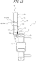
FIG. 13 is a side view of the magnetizing apparatus illustrated inFIG. 11 , viewed in the radial direction; -
FIG. 14 is a side view of the magnetizing apparatus illustrated inFIG. 11 , viewed in the axial direction; and -
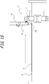
FIG. 15 illustrates a state in which the magnetizing apparatus illustrated inFIG. 11 is moved along a pipe. - Embodiments of the present disclosure are described below with reference to the drawings. The same reference sign is appended to corresponding elements across drawings.
- A magnetizing
apparatus 1 according to a first embodiment of the present disclosure, illustrated inFIGS. 1 to 4 , includes a circular, openable and closableannular portion 3 formed by amagnet 2. Theannular portion 3 includes alock mechanism 4 that holds theannular portion 3 in a closed state. Theannular portion 3 in the present embodiment is circular to correspond to acylindrical pipe 11 as the object of magnetization, described below. Theannular portion 3 may, however, also have a non-circular shape. For example, theannular portion 3 may have an annular shape forming an H-shape or an I-shape to correspond to H-shaped steel or I-shaped steel as the object of magnetization. - In the present embodiment, the axial direction in the context of the
annular portion 3 or themagnet 2 refers to the direction along the central axis O of theannular portion 3 when theannular portion 3 is closed. In the present embodiment, the peripheral direction in the context of theannular portion 3 or themagnet 2 refers to the direction encircling the central axis O of theannular portion 3 when theannular portion 3 is closed. In the present embodiment, the radial direction in the context of theannular portion 3 or themagnet 2 refers to the direction along a line orthogonal to the central axis O of theannular portion 3 when theannular portion 3 is closed. - As illustrated in
FIG. 5 , themagnet 2 is formed by twosemi-cylindrical portions 2a. Themagnet 2 extends over the entire periphery in the peripheral direction of theannular portion 3 when theannular portion 3 is closed. In other words, when theannular portion 3 is closed, oneperipheral end face 2b of oneportion 2a of themagnet 2 contacts oneperipheral end face 2b of theother portion 2a of themagnet 2, and the otherperipheral end face 2b of oneportion 2a of themagnet 2 contacts the otherperipheral end face 2b of theother portion 2a of themagnet 2. - The
magnet 2 has different polarities in the axial direction of theannular portion 3. That is, oneaxial end face 2c of themagnet 2 is the N pole, and the other axial end face 2c is the S pole. Themagnet 2 is a permanent magnet. Themagnet 2 is, for example, a neodymium magnet or a ferrite magnet. - As illustrated in
FIGS. 1 to 4 , theannular portion 3 is formed by a connectingmember 5 that interconnects the twoportions 2a of themagnet 2. In other words, theannular portion 3 is formed by themagnet 2 and the connectingmember 5. The connectingmember 5 covers eachportion 2a of themagnet 2. - The connecting
member 5 includes ahinge 6 that rotatably connects the twoportions 2a of themagnet 2. Thehinge 6 is a single-axis hinge that rotates around only one rotation axis P parallel to the central axis O of theannular portion 3. Thehinge 6 includes anend 6a that is provided integrally with oneportion 2a of themagnet 2 and anend 6a that is provided integrally with theother portion 2a of themagnet 2. Thehinge 6 is provided at the radial outer end of theannular portion 3. Thehinge 6 is a torque hinge having a predetermined rotational resistance. - The connecting
member 5 includes a slidingplate 7 that forms the inner peripheral surface of theannular portion 3. The slidingplate 7 is formed by twosemi-cylindrical portions 7a. Oneportion 7a of the slidingplate 7 covers the inner peripheral surface of oneportion 2a of themagnet 2, and theother portion 7a covers the inner peripheral surface of theother portion 2a of themagnet 2. Eachportion 7a of the slidingplate 7 is formed of a synthetic resin material. - The connecting
member 5 includeshandles 8 respectively provided at two locations on either side of thehinge 6 in the peripheral direction of theannular portion 3. Onehandle 8 is provided integrally with oneportion 2a of themagnet 2, and theother handle 8 is provided integrally with theother portion 2a of themagnet 2. Both of the twohandles 8 are provided at oneaxial end 3a of theannular portion 3. Eachhandle 8 is formed by a pair of rod-shapedends 8a extending parallel to the central axis O of theannular portion 3 and a rod-shapedintermediate portion 8b connecting the pair ofends 8a. The twointermediate portions 8b face each other in the radial direction of theannular portion 3 and extend parallel to each other. - The
hinge 6, the slidingplate 7, and the twohandles 8 are connected to a cover member 9. In other words, the connectingmember 5 is formed by thehinge 6, the slidingplate 7, the twohandles 8, and the cover member 9. The cover member 9 is formed by a portion 9a covering oneportion 2a of themagnet 2 and a portion 9a covering theother portion 2a of themagnet 2. Each portion 9a of the cover member 9 includes a radialouter end 9b facing the outer peripheral surface of themagnet 2, oneaxial end 9c facing oneaxial end face 2c of themagnet 2, and anotheraxial end 9c facing the otheraxial end face 2c of themagnet 2. - Each portion 9a of the cover member 9 is formed by a plurality of members that are fixed to each other. The plurality of members is formed of a metallic material such as steel. The fixing means for the plurality of members is, for example, fastening means such as screws, or welding.
- One
end 6a of thehinge 6 is fixed to the radialouter end 9b of one portion 9a of the cover member 9, and theother end 6a of thehinge 6 is fixed to the radialouter end 9b of the other portion 9a of the cover member 9. The fixing means is, for example, fastening means such as screws, or welding. Eachend 6a of thehinge 6 is, for example, formed of a metallic material such as steel. - One
portion 7a of the slidingplate 7 is fixed to the pair of axial ends 9c of one portion 9a of the cover member 9 by swaging, and theother portion 7a of the slidingplate 7 is fixed to the pair of axial ends 9c of the other portion 9a of the cover member 9 by swaging. - The pair of
ends 8a of onehandle 8 is fixed to oneaxial end 9c of one portion 9a of the cover member 9, and the pair ofends 8a of theother handle 8 is fixed to oneaxial end 9c of the other portion 9a of the cover member 9. The fixing means is, for example, fastening means such as screws, or welding. Eachhandle 8 is, for example, formed of a metallic material such as steel or a synthetic resin. - The
lock mechanism 4 is configured by atoggle latch 10 provided at both peripheral ends of theannular portion 3. Thetoggle latch 10 is formed by anengagement portion 10a provided at one peripheral end of theannular portion 3 and atoggle latch body 10b provided at the other peripheral end of theannular portion 3. Thetoggle latch body 10b includes an engagedportion 10c that is engaged with theengagement portion 10a. - The
toggle latch body 10b includes anoperation lever 10d that releases the engagement between theengagement portion 10a and the engagedportion 10c by rotating towards the radial outer side of theannular portion 3 about a first rotation axis Q1. Theoperation lever 10d is axially supported by the radialouter end 9b of one portion 9a of the cover member 9 in a rotatable manner about the first rotation axis Q1. Thetoggle latch body 10b includes an engagedmember 10e that is axially supported by theoperation lever 10d in a rotatable manner about a second rotation axis Q2 parallel to the first rotation axis Q1. The engagedmember 10e includes the engagedportion 10c. Theengagement portion 10a of thetoggle latch 10 is provided on anengagement member 10f fixed to the radialouter end 9b of the other portion 9a of the cover member 9. The fixing means is, for example, fastening means such as screws, or welding. Theoperation lever 10d, the engagedmember 10e, and theengagement member 10f are, for example, formed of a metallic material such as steel. - As illustrated in
FIGS. 6 to 8 , the magnetizingapparatus 1 can, for example, be used to achieve magnetization of thepipe 11 as a magnetic object, such as a ferromagnetic material, and provide thepipe 11 with residual magnetization, i.e., to magnetize thepipe 11. Specifically, a magnetizing method according to the present embodiment to magnetize thepipe 11 using the magnetizingapparatus 1 includes an attaching step, a moving step, and a detaching step. Thepipe 11 hasflanges 11a as irregularly shaped portions at both ends in the axial direction. In the examples illustrated inFIGS. 6 to 8 , thepipe 11 has a circular cross-sectional shape and extends in a straight line in the axial direction. Thepipe 11 has an outside diameter of, for example, 2 to 4 inches. Thepipe 11 is, for example, installed in a plant, bridge, or other structure. - In the attaching step, the
pipe 11 is placed inside theannular portion 3 by opening and closing the annular portion 3 (seeFIG. 6 ), and the magnetizingapparatus 1 is attached to thepipe 11 by holding theannular portion 3 in a closed state with the lock mechanism 4 (seeFIG. 7 ). The attaching step thus enables the magnetizingapparatus 1 to be attached to thepipe 11 that has irregularly shaped portions. - In the attaching step, a worker can easily open and close the
annular portion 3 by grasping the twohandles 8. At this time, thehinge 6 achieves a stable opening and closing operation of theannular portion 3. Thelock mechanism 4 is locked by the engagedportion 10c of thetoggle latch body 10b being engaged with theengagement portion 10a of thetoggle latch 10. - When the
annular portion 3 is attached to thepipe 11, the portion of thepipe 11 located on the radial inner side of themagnet 2 is uniformly magnetized in the peripheral direction by themagnet 2. In particular, since themagnet 2 has different polarities in the axial direction of theannular portion 3, thepipe 11 can be magnetized efficiently. - In the moving step, the magnetizing
apparatus 1 is moved relative to thepipe 11 in the axial direction of theannular portion 3 while the magnetizingapparatus 1 is attached to the pipe 11 (seeFIG. 8 ). At this time, theannular portion 3 moves in a straight line in the axial direction of thepipe 11. By performance of this moving step, thepipe 11 is magnetized in the moving range of theannular portion 3. In the moving step, the operator can easily move theannular portion 3 along thepipe 11 by grasping one or both of the twohandles 8. In the present embodiment, theannular portion 3 is moved during the moving step toward the side at which thehandles 8 are not provided, as illustrated inFIG. 8 . However, the attaching step may be performed so that theannular portion 3 can be moved toward the side at which thehandles 8 are provided in the moving step. By theannular portion 3 including the slidingplate 7, the sliding resistance between the magnetizingapparatus 1 and thepipe 11 is reduced to enable easy movement of the magnetizingapparatus 1 and also suppress scratching of thepipe 11. - In the detaching step, the magnetizing
apparatus 1 is detached from thepipe 11 by releasing thelock mechanism 4 after the moving step (not illustrated). At this time, the worker can easily release thelock mechanism 4 by operating theoperation lever 10d of thetoggle latch body 10b. When thelock mechanism 4 is released, theannular portion 3 opens due to the repulsive force of themagnet 2. At this time, since thehinge 6 is a torque hinge, the momentum of the opening of theannular portion 3 is suppressed, thereby ensuring safety. The detaching step enables the magnetizingapparatus 1 to be made available for another object. - According to the magnetizing method of the present embodiment, after the detaching step, detection means using a magnetic flaw detection method such as a magnetic powder flaw detection method or a magnetic flux leakage flaw detection method can be applied to the magnetized portion of the
pipe 11 to detect abnormalities in thepipe 11 accurately and quickly. For example, by installation of an abnormality detection apparatus 15 (seeFIG. 10 ) with a magnetic sensor on the magnetized portion of thepipe 11, abnormalities can be detected using a magnetic flux leakage flaw detection method. - A second embodiment of the present disclosure is illustrated next with reference to
FIGS. 9 and10 . - The magnetizing
apparatus 1 according to the present embodiment, illustrated inFIG. 9 , includes amarker holder 13 that detachably holds amarker 12. Themarker holder 13 forces themarker 12 toward the radial inner side of theannular portion 3. In the present embodiment, themarker holder 13 holds themarker 12 rotatably toward the radial inner side of theannular portion 3. - In greater detail, the
marker holder 13 is axially supported by oneaxial end 9c of the cover member 9 in a rotatable manner about a rotation axis R. The rotation axis R extends in a direction perpendicular to both the radial and axial directions of theannular portion 3. Themarker 12 is a pen. Themarker holder 13 includes an innerperipheral surface 13a that can be attached to and detached from the outer peripheral surface of themarker 12 and is centered on an axis S. Themarker 12 is disposed concentrically with the axis S by being held in themarker holder 13. Themarker holder 13 is forced from a state in which the axis S is inclined relative to the axial outer side of theannular portion 3 toward the radial inner side of the annular portion 3 (the state illustrated by a solid line inFIG. 9 ) toward a state in which the axis S extends along the radial direction of the annular portion 3 (the state illustrated by a dashed double dotted line inFIG. 9 ). The forcing means is, for example, a spring. - According to the magnetizing
apparatus 1 of the present embodiment, thepipe 11 can be magnetized by the same method as in the first embodiment. Also, according to the magnetizingapparatus 1 of the present embodiment, by performance of the moving step, a marking 14 can be applied to thepipe 11 by themarker 12 held in themarker holder 13. In other words, as illustrated inFIG. 9 , by the magnetizingapparatus 1 being moved along thepipe 11, themarker 12 can be moved along thepipe 11 together with theannular portion 3 while apen tip 12a of themarker 12 is pressed against the outer peripheral surface of thepipe 11 by themarker holder 13. As a result, a marking 14 corresponding to the magnetized area of thepipe 11 in the axial direction is applied, as illustrated inFIG. 10 . - Therefore, the magnetized portion of the
pipe 11 can be easily identified during application of detection means using a magnetic flaw detection method such as a magnetic powder flaw detection method or a magnetic flux leakage flaw detection method. For example, as illustrated inFIG. 10 , based on the marking 14, theabnormality detection apparatus 15 can accurately be installed at the magnetized portion of thepipe 11, thus enabling accurate detection of anomalies using a magnetic flux leakage flaw detection method. - A third embodiment of the present disclosure is illustrated next with reference to
FIGS. 11 to 15 . - The magnetizing
apparatus 1 according to the present embodiment, illustrated inFIGS. 11 ,13 , and14 , includes amarker holder 13 that detachably holds amarker 12. Themarker holder 13 forces themarker 12 toward the radial inner side of theannular portion 3. In the present embodiment, themarker holder 13 holds themarker 12 movably in the radial direction toward the radial inner side of theannular portion 3. - As illustrated in
FIG. 12 , themarker holder 13 includes afirst holder member 13b, asecond holder member 13c, a fixingmember 13d, and twotension springs 13e. The fixingmember 13d is configured by apressing member 13f and twofastening members 13g. Themarker 12 is a pen. - The
first holder member 13b is supported by oneaxial end 9c of the cover member 9 of theannular portion 3. Thesecond holder member 13c is fitted onto thefirst holder member 13b slidably along the radial direction. Thefirst holder member 13b and thesecond holder member 13c are connected by twotension springs 13e. Therefore, thesecond holder member 13c is forced towards the radial inner side by these tension springs 13e. The tension springs 13e are arranged on either side of theannular portion 3 in the peripheral direction with respect to themarker 12. Thesecond holder member 13c includes apressure portion 13h that pushes aback end 12c of atorso 12b of the marker 12 (the opposite end from thepen tip 12a) toward the radial inner direction of theannular portion 3. - The
marker 12 is fixed to thesecond holder member 13c by the fixingmember 13d. Thepressing member 13f of the fixingmember 13d includes arecess 13i, into which thetorso 12b of themarker 12 is inserted, andinsertion holes 13j located on either side of therecess 13i in the peripheral direction of theannular portion 3. Afastening member 13g is passed in the axial direction through each of theinsertion holes 13j, and by thefastening members 13g being fastened to thesecond holder member 13c, thetorso 12b of themarker 12 is clamped in the axial direction of theannular portion 3 by the pressingmember 13f and thesecond holder member 13c. - The
first holder member 13b includes abase 13k, which is a flat plate perpendicular to the axial direction and supported by oneaxial end 9c of the cover member 9, and twoside plates 131 that are located on either side of thetorso 12b of themarker 12 in the peripheral direction of theannular portion 3 and are perpendicular to thebase 13k. Between each of theside plates 131 and thebase 13k, aslit 13m extending along the radial direction and opening to the radial outer side is formed. - The
second holder member 13c includes amoveable plate 13n, which is a flat plate parallel to the base 13k of thefirst holder member 13b, and thepressure portion 13h, which is a flat plate perpendicular to themoveable plate 13n. Themoveable plate 13n includes slits 13o that respectively engage theslits 13m of thefirst holder member 13b. Each slit 13o extends along the radial direction and opens toward the radial inner side. By the meshing of theslits 13m and the slits 13o, thesecond holder member 13c can slide along the radial direction against thefirst holder member 13b. Themoveable plate 13n includesfastening holes 13p into which therespective fastening members 13g are fastened. - The two
tension springs 13e connect the base 13k of thefirst holder member 13b and themoveable plate 13n of thesecond holder member 13c at either side, in the peripheral direction of theannular portion 3, of the twoslits 13m and the two slits 13o. - In this way, the
marker holder 13 of the present embodiment includes thefirst holder member 13b supported by theannular portion 3, thesecond holder member 13c held by thefirst holder member 13b slidably along the radial direction of theannular portion 3, the fixingmember 13d that fixes themarker 12 to thesecond holder 13c, and the twotension springs 13e as a forcing member that forces thesecond holder member 13c towards the radial inner side of theannular portion 3. - According to the magnetizing
apparatus 1 of the present embodiment, thepipe 11 can be magnetized by the same method as in the second embodiment. Also, according to the magnetizingapparatus 1 of the present embodiment, by performance of the moving step, a marking 14 can be applied to thepipe 11 by themarker 12 held in themarker holder 13. In other words, as illustrated by the arrow inFIG. 15 , by the magnetizingapparatus 1 being moved along thepipe 11, themarker 12 can be moved along thepipe 11 together with theannular portion 3 while thepen tip 12a of themarker 12 is pressed against the outer peripheral surface of thepipe 11 by themarker holder 13. As a result, a marking 14 corresponding to the magnetized area of thepipe 11 in the axial direction is applied, as in the second embodiment. Therefore, the magnetized portion of thepipe 11 can be easily identified during application of detection means using a magnetic flaw detection method. - The
marker holder 13 of the present embodiment can be modified in various ways. In other words, themarker holder 13 of the present embodiment may be configured to hold themarker 12 movably in the radial direction toward the radial inner side of theannular portion 3. In a case in which themarker holder 13 of the present embodiment includes thefirst holder member 13b, thesecond holder member 13c, the fixingmember 13d, and the forcing member (for example, the tension springs 13e), it suffices for themarker holder 13 to include thefirst holder member 13b supported by theannular portion 3, thesecond holder member 13c held by thefirst holder member 13b slidably along the radial direction of theannular portion 3, the fixingmember 13d that fixes themarker 12 to thesecond holder 13c, and a forcing member that forces thesecond holder member 13c towards the radial inner side of theannular portion 3. - Each of the above embodiments is only one example of the present disclosure, and various changes may be made, such as those described below.
- It suffices for the magnetizing
apparatus 1 to include the circular or non-circular openable and closeableannular portion 3 formed by themagnet 2, and for theannular portion 3 to include thelock mechanism 4 configured to hold theannular portion 3 in a closed state. - Each
portion 2a of themagnet 2 is not limited to a semi-cylindrical shape. Themagnet 2 is not limited to being formed by twoportions 2a and may, for example, be formed by three or more portions. Themagnet 2 is not limited to extending over the entire periphery in the peripheral direction of theannular portion 3 when theannular portion 3 is closed. Themagnet 2 is not limited to having different polarities in the axial direction of theannular portion 3 and may, for example, have different polarities in the radial direction of theannular portion 3. Themagnet 2 is not limited to being a permanent magnet and may be an electromagnet. - The
annular portion 3 is not limited to being formed by the connectingmember 5. The connectingmember 5 is not limited to covering eachportion 2a of themagnet 2. In a case in which themagnet 2 is formed by three ormore portions 2a, the connectingmember 5 may include two ormore hinges 6 to rotatably connect theportions 2a of themagnet 2 that are adjacent to each other in the peripheral direction of theannular portion 3. Thehinge 6 is not limited to a torque hinge. Thehinge 6 is not limited to a single-axis hinge. Thehinge 6 is not limited to being provided at the radial outer end of theannular portion 3. Theannular portion 3 is not limited to including thehinge 6. For example, theannular portion 3 may be formed from a deformable,soft material magnet 2. - The connecting
member 5 is not limited to including the slidingplate 7. Eachportion 7a of the slidingplate 7 is not limited to a semi-cylindrical shape. The slidingplate 7 is not limited to being formed by twoportions 2a and may, for example, be formed by three ormore portions 7a to match the number ofportions 2a of themagnet 2. Eachportion 7a of the slidingplate 7 is not limited to being formed of a synthetic resin material. - The connecting
member 5 is not limited to including thehandles 8. Thehandles 8 are not limited to being provided respectively at two locations on either side of thehinge 6 in the peripheral direction of theannular portion 3. The twohandles 8 are both not limited to being provided at oneaxial end 3a of theannular portion 3. Thehandles 8 are not limited to being formed by the pair ofends 8a and theintermediate portion 8b. - The connecting
member 5 is not limited to including the cover member 9. The cover member 9 is not limited to being formed by two portions 9a and may, for example, be formed by three or more portions 9a to match the number ofportions 2a of themagnet 2. Each portion 9a of the cover member 9 is not limited to including the radialouter end 9b facing the outer peripheral surface of themagnet 2, oneaxial end 9c facing oneaxial end face 2c of themagnet 2, and anotheraxial end 9c facing the otheraxial end face 2c of themagnet 2. Each portion 9a of the cover member 9 is not limited to being formed by a plurality of members. The plurality of members configuring the portions 9a of the cover member 9 are not limited to being formed of a metallic material. The portions 9a of the cover member 9 are not limited to fixing theportions 7a of the slidingplate 7 by swaging. - The
lock mechanism 4 is not limited to being configured by thetoggle latch 10. For example, thelock mechanism 4 may be configured by fastening means such as a screw that detachably connects the peripheral ends of theannular portion 3. Thetoggle latch 10 is not limited to being provided at the peripheral ends of theannular portion 3. - The object to be magnetized by the magnetizing
apparatus 1 is not limited to thepipe 11. The object may, for example, be a column, beam, or the like in a plant, bridge, or other structure. The object may, for example, be structural material such as H-shaped steel or I-shaped steel. Thepipe 11 is not limited to having a circular cross-sectional shape. Thepipe 11 is not limited to extension in a straight line in the axial direction. For example, thepipe 11 may include a corner that bends to form an angle such as a right angle. - The magnetizing
apparatus 1 is not limited to being configured for detachment after magnetization of the object to enable application of detection means using a magnetic flaw detection method. For example, the magnetizingapparatus 1 may be configured so that detection means using a magnetic flaw detection method can be applied while the magnetizingapparatus 1 is still attached to the object. For example, the magnetizingapparatus 1 may be used to demagnetize a magnetized object. - The
marker holder 13 is not limited to being attachable to and detachable from themarker 12. Themarker holder 13 is not limited to forcing themarker 12 toward the radial inner side of theannular portion 3. Themarker holder 13 is not limited to being axially supported by oneaxial end 9c of the cover member 9. Themarker 12 is not limited to being a pen. The magnetizingapparatus 1 may include a plurality ofmarker holders 13 aligned in the peripheral direction of theannular portion 3. A plurality ofabnormality detection apparatuses 15 may be installed in correspondence with a plurality ofmarkings 14 applied using the plurality ofmarker holders 13. -
- 1
- Magnetizing apparatus
- 2
- Magnet
- 2a
- Portion
- 2b
- Peripheral end face
- 2c
- Axial end face
- 3
- Annular portion
- 3a
- Axial end
- 4
- Lock mechanism
- 5
- Connecting member
- 6
- Hinge
- 6a
- End
- 7
- Sliding plate
- 7a
- Portion
- 8
- Handle
- 8a
- End
- 8b
- Intermediate portion
- 9
- Cover member
- 9a
- Portion
- 9b
- Radial outer end
- 9c
- Axial end
- 10
- Toggle latch
- 10a
- Engagement portion
- 10b
- Toggle latch body
- 10c
- Engaged portion
- 10d
- Operation lever
- 10e
- Engaged member
- 10f
- Engagement member
- 11
- Pipe
- 11a
- Flange
- 12
- Marker
- 12a
- Pen tip
- 12b
- Torso
- 12c
- Back end
- 13
- Marker holder
- 13a
- Inner peripheral surface
- 13b
- First holder member
- 13c
- Second holder member
- 13d
- Fixing member
- 13e
- Tension spring (forcing member)
- 13f
- Pressing member
- 13g
- Fastening member
- 13h
- Pressure portion
- 13i
- Recess
- 13j
- Insertion hole
- 13k
- Base
- 131
- Side plate
- 13m
- Slit
- 13n
- Moveable plate
- 13o
- Slit
- 13p
- Fastening hole
- 14
- Marking
- 15
- Anomaly detection apparatus
- O
- Central axis
- P
- Rotation axis
- Q1
- First rotation axis
- Q2
- Second rotation axis
- R
- Rotation axis
- S
- Axis
Claims (10)
- A magnetizing apparatus comprising:a circular or non-circular openable and closeable annular portion formed by a magnet,wherein the annular portion comprises a lock mechanism configured to hold the annular portion in a closed state.
- The magnetizing apparatus according to claim 1, further comprising a marker holder configured to hold a marker.
- The magnetizing apparatus according to claim 1 or 2, wherein the magnet has different polarities in an axial direction of the annular portion.
- The magnetizing apparatus according to any one of claims 1 to 3, wherein the magnet comprises a plurality of portions interconnected in a peripheral direction of the annular portion.
- The magnetizing apparatus according to claim 4, wherein the annular portion comprises a hinge rotatably connecting portions of the magnet, among the plurality of portions, that are adjacent in the peripheral direction of the annular portion.
- The magnetizing apparatus according to claim 5, wherein the hinge is a torque hinge with a predetermined rotational resistance.
- The magnetizing apparatus according to any one of claims 1 to 6, wherein the lock mechanism is configured by a toggle latch provided at both peripheral ends of the annular portion.
- The magnetizing apparatus according to any one of claims 1 to 7, wherein the annular portion comprises a sliding plate that forms an inner peripheral surface of the annular portion.
- A magnetizing method for magnetizing an object using the magnetizing apparatus according to claim 1, the magnetizing method comprising:an attaching step of attaching the magnetizing apparatus to the object by opening and closing the annular portion to place the object inside the annular portion and holding the annular portion in a closed state with the lock mechanism;a moving step of moving the magnetizing apparatus relative to the object in an axial direction of the annular portion while the magnetizing apparatus is attached to the object; anda detaching step, after the moving step, of releasing the lock mechanism to detach the magnetizing apparatus from the object.
- The magnetizing method according to claim 9,wherein the magnetizing apparatus comprises a marker holder, andwherein the magnetizing method further comprises a marking step of applying a marking to the object, by performing the moving step, with a marker held by the marker holder.
Applications Claiming Priority (2)
| Application Number | Priority Date | Filing Date | Title |
|---|---|---|---|
| JP2020044810A JP7314842B2 (en) | 2020-03-13 | 2020-03-13 | Magnetizing device and magnetizing method |
| PCT/JP2021/008544 WO2021182309A1 (en) | 2020-03-13 | 2021-03-04 | Magnetization device and magnetizing method |
Publications (2)
| Publication Number | Publication Date |
|---|---|
| EP4120294A1 true EP4120294A1 (en) | 2023-01-18 |
| EP4120294A4 EP4120294A4 (en) | 2024-03-20 |
Family
ID=77671651
Family Applications (1)
| Application Number | Title | Priority Date | Filing Date |
|---|---|---|---|
| EP21768102.2A Pending EP4120294A4 (en) | 2020-03-13 | 2021-03-04 | MAGNETIZATION DEVICE AND MAGNETIZATION METHOD |
Country Status (5)
| Country | Link |
|---|---|
| US (1) | US12300412B2 (en) |
| EP (1) | EP4120294A4 (en) |
| JP (1) | JP7314842B2 (en) |
| AU (1) | AU2021233649A1 (en) |
| WO (1) | WO2021182309A1 (en) |
Families Citing this family (1)
| Publication number | Priority date | Publication date | Assignee | Title |
|---|---|---|---|---|
| JP2024081514A (en) * | 2022-12-06 | 2024-06-18 | 横河電機株式会社 | Magnetizing device |
Family Cites Families (13)
| Publication number | Priority date | Publication date | Assignee | Title |
|---|---|---|---|---|
| JPS59226858A (en) * | 1983-06-07 | 1984-12-20 | Sumitomo Metal Ind Ltd | Flaw detector |
| JPS6312110A (en) * | 1986-03-14 | 1988-01-19 | Asahi Chem Ind Co Ltd | Uniform magnetic field generator |
| US5319335A (en) * | 1992-07-29 | 1994-06-07 | Industrial Technology Research Institute | Apparatus for magnetizing a magnetic roller |
| JP2556957Y2 (en) | 1993-04-13 | 1997-12-08 | 東京製綱株式会社 | Wire rope damage detector |
| US5711085A (en) * | 1996-05-21 | 1998-01-27 | Adams; Thomas F. | Writing instrument holding clip for retractable tape |
| US7538650B2 (en) * | 2006-07-17 | 2009-05-26 | Smith International, Inc. | Apparatus and method for magnetizing casing string tubulars |
| JP4273249B1 (en) * | 2007-10-29 | 2009-06-03 | 有限会社クラ技術研究所 | Magnetic flux amount control method, excitation device, and magnetic adsorption device using magnetic flux amount control method |
| CN102360696B (en) * | 2011-06-10 | 2013-07-31 | 沈阳隆基电磁科技股份有限公司 | Open and close type monocrystal permanent magnetic field structure |
| CN106537134B (en) | 2014-05-18 | 2019-12-10 | 查尔斯斯塔克德雷珀实验室有限公司 | System and method for measuring defects in ferromagnetic materials |
| JP6623950B2 (en) | 2016-06-20 | 2019-12-25 | 日本製鉄株式会社 | Titanium plate excellent in balance between proof stress and ductility and method for producing the same |
| CN207408346U (en) | 2017-11-16 | 2018-05-25 | 东北石油大学 | A kind of pipe fitting Magnetic Flux Leakage Testing Instrument and apply its pipe fitting Magnetic Flux Leakage Testing System |
| JP7403149B2 (en) * | 2018-11-12 | 2023-12-22 | 学校法人近畿大学 | Piping magnetization method, piping magnetization device, piping inspection method and piping inspection device |
| JP7147801B2 (en) * | 2020-03-13 | 2022-10-05 | 横河電機株式会社 | Magnetic flaw detection method, magnetic field measurement processing device, and magnetic flaw detection device |
-
2020
- 2020-03-13 JP JP2020044810A patent/JP7314842B2/en active Active
-
2021
- 2021-03-04 WO PCT/JP2021/008544 patent/WO2021182309A1/en not_active Ceased
- 2021-03-04 EP EP21768102.2A patent/EP4120294A4/en active Pending
- 2021-03-04 AU AU2021233649A patent/AU2021233649A1/en not_active Abandoned
- 2021-03-04 US US17/906,006 patent/US12300412B2/en active Active
Also Published As
| Publication number | Publication date |
|---|---|
| JP2021145119A (en) | 2021-09-24 |
| WO2021182309A1 (en) | 2021-09-16 |
| US20230119946A1 (en) | 2023-04-20 |
| AU2021233649A1 (en) | 2022-10-06 |
| JP7314842B2 (en) | 2023-07-26 |
| US12300412B2 (en) | 2025-05-13 |
| EP4120294A4 (en) | 2024-03-20 |
Similar Documents
| Publication | Publication Date | Title |
|---|---|---|
| US12300412B2 (en) | Magnetizing apparatus and magnetizing method | |
| US11608855B2 (en) | Tooling and methods for clocking dual eccentric bushings of a clevis | |
| US7272878B2 (en) | Cam actuated clamp apparatus | |
| JPH0687861U (en) | Wire rope damage detector | |
| EP3339852A1 (en) | Non-destructive inspection methods for round holes with multi-sensor probes | |
| EP3857108B1 (en) | Pipe coupling with improved tensioning system | |
| US7213803B2 (en) | Clamp and method for operating same | |
| US11137240B1 (en) | Pipe alignment tool | |
| AU2017380680B2 (en) | Cable lockout assembly | |
| US5524910A (en) | Independent chuck jaw insert having a registration surface enabling locking at a specific position | |
| WO2006041712A1 (en) | Magnetic spring clamp | |
| JP2000094345A (en) | Vice | |
| JP2009166173A (en) | Detaching tool for e-type snap ring | |
| US12300430B2 (en) | Magnet holding device, magnetization device, and magnetizing method | |
| US3176495A (en) | Pipe calking tool | |
| US20070013468A1 (en) | Means to increase or decrease magnetic strength in permanent magnetic clamping devices | |
| US20250100094A1 (en) | Clamping device, particularly for a workpiece carrier for a cable | |
| JP2004184214A (en) | Specimen fixing device of balancing tester | |
| JPH081381A (en) | Matching device for pipe | |
| US3999880A (en) | Drilling fixture for use in precisely drilling long bores | |
| CA3113156C (en) | Pipe coupling with tensioning system | |
| JP2012175728A (en) | Retainer for overhead wire and method of retaining overhead wire using the same | |
| MUKHTAR et al. | DESIGN AND IMPLEMENTATION OF SPOT WELDING TRAINER FOR BODY SHOP ASSEMBLY LINE | |
| JP2010021923A (en) | Waveguide connection structure | |
| KR20170088207A (en) | Fit Up Jig for Nozzle |
Legal Events
| Date | Code | Title | Description |
|---|---|---|---|
| STAA | Information on the status of an ep patent application or granted ep patent |
Free format text: STATUS: THE INTERNATIONAL PUBLICATION HAS BEEN MADE |
|
| PUAI | Public reference made under article 153(3) epc to a published international application that has entered the european phase |
Free format text: ORIGINAL CODE: 0009012 |
|
| STAA | Information on the status of an ep patent application or granted ep patent |
Free format text: STATUS: REQUEST FOR EXAMINATION WAS MADE |
|
| 17P | Request for examination filed |
Effective date: 20220912 |
|
| AK | Designated contracting states |
Kind code of ref document: A1 Designated state(s): AL AT BE BG CH CY CZ DE DK EE ES FI FR GB GR HR HU IE IS IT LI LT LU LV MC MK MT NL NO PL PT RO RS SE SI SK SM TR |
|
| DAV | Request for validation of the european patent (deleted) | ||
| DAX | Request for extension of the european patent (deleted) | ||
| P01 | Opt-out of the competence of the unified patent court (upc) registered |
Effective date: 20230606 |
|
| A4 | Supplementary search report drawn up and despatched |
Effective date: 20240216 |
|
| RIC1 | Information provided on ipc code assigned before grant |
Ipc: H01F 13/00 20060101ALI20240212BHEP Ipc: G01N 27/83 20060101ALI20240212BHEP Ipc: H01F 7/02 20060101AFI20240212BHEP |