EP4120085A1 - Failure analysis support device and failure analysis support method - Google Patents
Failure analysis support device and failure analysis support method Download PDFInfo
- Publication number
- EP4120085A1 EP4120085A1 EP22182876.7A EP22182876A EP4120085A1 EP 4120085 A1 EP4120085 A1 EP 4120085A1 EP 22182876 A EP22182876 A EP 22182876A EP 4120085 A1 EP4120085 A1 EP 4120085A1
- Authority
- EP
- European Patent Office
- Prior art keywords
- failure
- occurrence
- failures
- processing
- variables
- Prior art date
- Legal status (The legal status is an assumption and is not a legal conclusion. Google has not performed a legal analysis and makes no representation as to the accuracy of the status listed.)
- Granted
Links
Images











Classifications
-
- G—PHYSICS
- G06—COMPUTING OR CALCULATING; COUNTING
- G06F—ELECTRIC DIGITAL DATA PROCESSING
- G06F11/00—Error detection; Error correction; Monitoring
- G06F11/36—Prevention of errors by analysis, debugging or testing of software
- G06F11/3604—Analysis of software for verifying properties of programs
-
- G—PHYSICS
- G06—COMPUTING OR CALCULATING; COUNTING
- G06F—ELECTRIC DIGITAL DATA PROCESSING
- G06F11/00—Error detection; Error correction; Monitoring
- G06F11/07—Responding to the occurrence of a fault, e.g. fault tolerance
- G06F11/0703—Error or fault processing not based on redundancy, i.e. by taking additional measures to deal with the error or fault not making use of redundancy in operation, in hardware, or in data representation
- G06F11/079—Root cause analysis, i.e. error or fault diagnosis
-
- G—PHYSICS
- G06—COMPUTING OR CALCULATING; COUNTING
- G06F—ELECTRIC DIGITAL DATA PROCESSING
- G06F11/00—Error detection; Error correction; Monitoring
- G06F11/36—Prevention of errors by analysis, debugging or testing of software
- G06F11/362—Debugging of software
- G06F11/3624—Debugging of software by performing operations on the source code, e.g. via a compiler
-
- G—PHYSICS
- G06—COMPUTING OR CALCULATING; COUNTING
- G06F—ELECTRIC DIGITAL DATA PROCESSING
- G06F11/00—Error detection; Error correction; Monitoring
- G06F11/36—Prevention of errors by analysis, debugging or testing of software
- G06F11/362—Debugging of software
- G06F11/3644—Debugging of software by instrumenting at runtime
Definitions
- the present invention relates to a failure analysis support device and a failure analysis support method.
- embedded control software controls industrial equipment, and the like, and occurrence of failures is directly linked to manufacturing quality such as yield and recall.
- a failure is identified before release, and a test is performed to correct the failure.
- a test is performed to correct the failure.
- an input and an output in the software are created in advance as a test case, and it is confirmed whether the software returns a correct output that is assumed for the input of the test case.
- a developer analyzes in which part of the software unexpected processing has been performed, specifies a cause part and corrects logic of a program so that appropriate input and output are performed.
- This technique is a method for evaluating reliability of a software component in which a computer having a model format verification function executes: a specification information acquisition step of acquiring specification information including an input interface specification, an output interface specification, and an internal specification of the software component; a verification step of verifying the software component by the format verification function in accordance with specification information obtained by changing the input interface specification in the specification information to a value other than a normal value; and a failure propagation path storage step of storing an input obtained by changing the value other than the normal value and an output not satisfying the output interface specification in association with each other in a case where an example of an output value not satisfying the output interface specification is found in the verification step.
- a failure analysis support device of the present invention that solves the above problems includes: a storage device configured to store a source code of software to be processed; and an arithmetic device configured to execute processing of regenerating occurrence paths of all failures on a basis of the source code, processing of merging the occurrence paths of all the failures and generating a failure occurrence graph in which information on variable definitions and usage in the occurrence paths is integrated, processing of searching for an instance corresponding to a failure relationship pattern defined in advance for a relationship between failures in the failure occurrence graph, and processing of outputting a result of the search to a predetermined device.
- an information processing device stores a source code of software to be processed in a storage device, and executes processing of regenerating occurrence paths of all failures on a basis of the source code, processing of merging the occurrence paths of all the failures to generate a failure occurrence graph in which information of variable definitions and usage in the occurrence paths is integrated, processing of searching for an instance corresponding to a failure relationship pattern defined in advance for a relationship between failures in the failure occurrence graph, and processing of outputting a result of the search to a predetermined device.
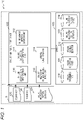
- Fig. 1 is a configuration diagram of a system including a failure analysis support device 100 according to the present embodiment.
- the failure analysis support device 100 illustrated in Fig. 1 is a computer capable of effectively avoiding duplication of analysis and correction with respect to a plurality of failures included in one program and supporting consistent correction.
- the failure analysis support device 100 of the present embodiment is communicably connected to a terminal 5 connected via an appropriate interface 1 (or a communication line).
- a failure analysis support system 10 may be collectively referred to as a failure analysis support system 10.
- the failure analysis support device 100 can also be said to be, for example, a server that provides a failure analysis support service operated by a business operator responsible for system development, a vendor supporting the business operator, or the like.
- the failure analysis support device 100 acquires information on a source code 125, a failure log 136, and a failure relationship pattern definition 127 from the terminal 5 and stores various kinds of information 130 to 134 generated on the basis of the information in a storage device 101 of the failure analysis support device 100.
- Various kinds of information 130 to 134 are, for example, a failure occurrence path 130, a failure occurrence graph 131, a failure variable definition 132, a failure relationship pattern definition 133, and a failure relationship pattern instance 134. These will be described later.
- the failure analysis support device 100 includes functional units such as a failure occurrence path regeneration unit 110, a failure occurrence graph generation unit 111, a failure variable definition extraction unit 112, a failure relationship pattern instance search unit 113, and an analysis result display unit 114.
- the failure occurrence path regeneration unit 110 is a functional unit that regenerates occurrence paths 130 of all failures on the basis of the source code 125 obtained from the terminal 5.
- the failure occurrence paths 130 regenerated in this way are temporarily stored in a memory 103.
- the failure occurrence graph generation unit 111 is a functional unit that merges the occurrence paths 130 of all the failures generated by the failure occurrence path regeneration unit 110 described above and generates the failure occurrence graph 131 in which information on variable definitions and usage in the occurrence paths 130 is integrated.
- the failure occurrence graph 131 generated in this manner is temporarily stored in the memory 103. It is assumed that the failure occurrence graph generation unit 111 uses the information on the variable definition 132 and the usage in the failure data extracted by the failure variable definition extraction unit 112 for the integration.
- the failure relationship pattern instance search unit 113 is a functional unit that searches for an instance corresponding to the failure relationship pattern definition 133 in the failure occurrence graph 131 described above.
- the failure relationship pattern definition 133 is the failure relationship pattern 127 obtained from the terminal 5 and stored in the memory 103 and is a definition related to a relationship between failures.
- the analysis result display unit 114 serves as a functional unit that outputs a result of the search by the failure relationship pattern instance search unit 113 described above to the terminal 5 or a predetermined output interface.
- the terminal 5 is a terminal to be used by a person in charge of a business operator who uses the above-described failure analysis support service. Specifically, a personal computer, a smartphone, a tablet terminal, or the like, can be assumed.
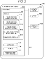
- the hardware configuration of the failure analysis support device 100 of the present embodiment is as follows in Fig. 2 .
- the failure analysis support device 100 includes the storage device 101, the memory 103, the arithmetic device 104, and the communication device 105.
- the storage device 101 includes an appropriate non-volatile storage element such as a solid state drive (SSD) and a hard disk drive.
- SSD solid state drive
- hard disk drive a non-volatile storage element
- the memory 103 includes a volatile storage element such as a RAM.
- the arithmetic device 104 is a CPU that executes a program 102 stored in the storage device 101 by reading the program to the memory 103, performs integrated control of the device itself and performs various kinds of determination, calculation, and control processing.
- Functional units obtained by executing the program 102 are the above-described failure occurrence path regeneration unit 110, failure occurrence graph generation unit 111, failure variable definition extraction unit 112, failure relationship pattern instance search unit 113, and analysis result display unit 114.
- the communication device 105 is assumed to be a network interface card, or the like, that is connected to a network 1 and is responsible for communication processing with the terminal 5.
- failure analysis support device 100 is standalone machine, it is preferable to further include an input device that receives key input or voice input from a user, and an output device such as a display that displays processing data.
- At least the source code 125, the failure log 126, and the failure relationship pattern definition 127 obtained from the terminal 5 are stored in the storage device 101.
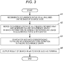
- Fig. 3 is a view illustrating a flow example of the failure analysis support method according to the present embodiment.
- the failure analysis support device 100 regenerates the occurrence paths 130 of all failures on the basis of the source code 125 (see Fig. 4 ) (s1).
- the failure analysis support device 100 merges the occurrence paths 130 of all the failures obtained in s1 and generates the failure occurrence graph 131 in which information on the variable definitions 132 and usage in the occurrence paths 130 is integrated (s2).
- the failure analysis support device 100 searches for an instance corresponding to the failure relationship pattern definition 133 in the above-described failure occurrence graph 131 (s3).
- the failure analysis support device 100 outputs a result of the search in s3 to a device such as the terminal 5 (s4) and ends the processing.
- failure occurrence path regeneration processing by symbol execution constituting the failure occurrence path regeneration (s1) in the above-described main flow will be described with reference to Figs. 5 to 11 .
- generation (s2) of the failure occurrence graph 131 will also be described.
- the failure occurrence path regeneration unit 110 calculates a symbol execution analysis route that passes through all target functions, which are functions including failure positions, using a function calling relationship in the target source code 125 (s21).
- the failure occurrence path regeneration unit 110 acquires a list of target functions that are functions including the failure positions (s211).
- failure occurrence path regeneration unit 110 analyzes a function calling relationship (a relationship between a caller and a callee) between the target functions (s212).
- the failure occurrence path regeneration unit 110 searches for the shortest route connecting the target functions connected by the function calling relationship (s213).
- failure occurrence path regeneration unit 110 assigns an execution order via an order of the callee and the caller to each function in the route for each route obtained in s213 (s214) and ends the processing.
- the failure occurrence path regeneration unit 110 adds, for example, a code of "assert (!failure condition)" before statement of the failure positions (see Fig. 9 ) and integrates a failure condition into the target functions including them (s22).
- the positions of the code added here are referred to as an integrated failure position.
- the failure occurrence path regeneration unit 110 performs symbol execution from a function of the symbol execution analysis route with the smallest execution order (s23). Note that it is assumed that functions of different subroutes can be executed in parallel. Subsequently, the failure occurrence path regeneration unit 110 stores information such as an execution path and a constraint in the storage device 101 (s24). An example of the execution path obtained by such symbol execution is illustrated in Fig. 10 .
- the failure occurrence path regeneration unit 110 determines whether all the functions of the symbol execution analysis route have been executed (s25).
- the failure occurrence path regeneration unit 110 continues symbol execution of the function subsequent in the execution order (s26).
- the failure occurrence path regeneration unit 110 acquires the failure occurrence paths 130 that are execution paths ended by the integrated failure position (see Fig. 11 ) (s27) and ends the processing.
- failure occurrence path regeneration processing by log analysis constituting the failure occurrence path regeneration (s1) in the main flow described above will be described with reference to Figs. 12 to 15 .
- generation (s2) of the failure occurrence graph 131 will also be described.
- the failure occurrence path regeneration unit 110 searches the failure log 126 for input values that become causes of the failures in the target functions (s32). Note that an original source code 125 having a log function that outputs input values of a function to a log is assumed.
- failure occurrence path regeneration unit 110 instruments (see Fig. 13 ) the target functions in order to record the execution trace including the executed statement and the information on the execution order (s32).
- the failure occurrence path regeneration unit 110 executes the above-described target functions using the input values that become the causes of the failures searched in s31 (s33).
- failure occurrence path regeneration unit 110 extracts the failure occurrence paths from the log of the execution trace obtained in s33 (see Fig. 14 ) (s34) and ends the processing.
- the failure analysis support device 100 which has regenerated the failure occurrence paths, merges the occurrence paths 130 of all the failures obtained in s1 and generates the failure occurrence graph 131 (see Fig. 15 ) in which the information on the variable definitions 132 and the usage in the occurrence paths 130 is integrated.
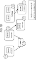
- a basic structure of the failure occurrence graph 131 includes nodes in which the definition information (statement) of the failure occurrence paths is set, information (such as failure IDs and path IDs) of the failure occurrence paths passing through the nodes, data flow information which is information on variable definitions and usage (predicate, calculate) in the respective nodes, and edges connecting the nodes in the order described in the failure occurrence paths.
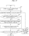
- the failure relationship pattern instance search unit 113 extracts failure data from the failure occurrence graph 131 for each failure (s50).
- An example of such a failure occurrence graph 131 is illustrated in Fig. 18 . Further, details of s50 are illustrated in the flow in Fig. 17 .
- the failure relationship pattern instance search unit 113 adds a node (current node) corresponding to the integrated failure occurrence path (s501).
- failure relationship pattern instance search unit 113 acquires variable use information, c-use, or p-use of the current node (s502).
- the failure relationship pattern instance search unit 113 determines whether the node has a plurality of pieces of variable use information and whether the node is the first node in the failure occurrence path (s503).
- the failure relationship pattern instance search unit 113 causes the processing to transition to s506.
- the failure relationship pattern instance search unit 113 searches for the closest variable definition X in the failure occurrence path of the failure A defining x for each unprocessed variable x in the variable use information of the current node (s504).
- the failure relationship pattern instance search unit 113 adds X and edges labeled from X to x to the current node as a new node and new vertexes of the graph (s505).
- failure relationship pattern instance search unit 113 determines whether there is a node in a list of nodes under consideration (s506).
- the failure relationship pattern instance search unit 113 selects a node from the list of nodes under consideration, sets the node as the current investigation target node (s507) and returns the processing to s502.
- the failure relationship pattern instance search unit 113 ends the processing.
- the failure relationship pattern instance search unit 113 acquires an unprocessed failure pair (s51).
- the failure relationship pattern instance search unit 113 collates a result of merging the variable definitions and the like of the failures in the failure pair with the failure relationship pattern definition 127 to specify a pattern (s52).
- failure relationship pattern instance search unit 113 determines whether the failures of the pair have a shared edge (s53).
- the failure relationship pattern instance search unit 113 specifies that the pair has a data-dependent failure relationship pattern ( Fig. 19A ) (s54) and causes the processing to transition to s59. Note that for the pair, data correlation between the failures is calculated on the basis of, for example, a data correlation calculation formula 201 ( Fig. 20 ).
- the failure relationship pattern instance search unit 113 compares the failure occurrence paths of the failures of the pair (s55).
- the failure relationship pattern instance search unit 113 determines whether the failure occurrence paths include a shared node (s56).
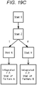
- the failure relationship pattern instance search unit 113 specifies that the pair has a control-dependent failure relationship pattern ( Fig. 19C ) (s57) and causes the processing to transition to s59.
- the failure relationship pattern instance search unit 113 specifies that the pair has a failure relationship pattern having an independent relationship (s58).
- failure relationship pattern instance search unit 113 determines whether all the pairs have been processed (s59).
- the failure relationship pattern instance search unit 113 returns the processing to s51.
- the failure relationship pattern instance search unit 113 ends the processing.
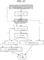
- the analysis result display unit 114 in the failure analysis support device 100 of the present embodiment distribute data of the failure occurrence graph 131 obtained so far to, for example, the terminal 5 to display ( Fig. 21 ).
- the source code ( Fig. 22 ) in which all the failure occurrence paths are merged may be distributed to the terminal 5 and displayed.
- the arithmetic device when generating the failure occurrence graph, may set definition information on variables of the occurrence paths of the failures to nodes, set usage of the variables set to the nodes as a data flow and connect the nodes by edges along an order described in the occurrence paths to thereby generate the failure occurrence graph.
- the arithmetic device when searching for the instance, may execute processing of extracting information including definitions of the variables of the failures, graph elements to be used to describe the definitions of the variables, and usage of all variables appearing in a failure state from the failure occurrence graph for each failure, processing of specifying an unprocessed failure pair, comparing a result of merging the definitions of the variables of failures in the failure pair and the graph elements with the failure relationship pattern and determining a corresponding failure relationship pattern, processing of determining whether the definitions of the variables in the failure pair and the graph elements include a shared edge, processing of comparing occurrence paths of the failures in the failure pair in a case where the definitions of the variables of the failure pair and the graph elements do not include the shared edge as a result of determination regarding the shared edge, determining whether the occurrence paths include a shared node, and specifying that the failures are independent of each other in a case where the occurrence paths do not include the shared node, processing of calculating data
- the information processing device may set definition information on variables of occurrence paths of failures to nodes, set usage of the variables set to the nodes as a data flow, and connect the nodes by edges along an order described in the occurrence paths to thereby generate the failure occurrence graph.
- the information processing device may execute, when searching for the instance, processing of extracting information on definitions of the variables of failures, graph elements to be used to describe the definitions of the variables, and usage of all variables appearing in a failure state from the failure occurrence graph for each failure, processing of specifying an unprocessed failure pair, comparing a result of merging the definitions of the variables of failures in the failure pair and the graph elements with the failure relationship pattern and determining a corresponding failure relationship pattern, processing of determining whether the definitions of the variables in the failure pair and the graph elements include a shared edge, processing of comparing occurrence paths of the failures in the failure pair in a case where the definitions of the variables in the failure pair and the graph elements do not include the shared edge as a result of determination regarding the shared edge, determining whether the occurrence paths include a shared node, and specifying that the failures are independent of each other in a case where the occurrence paths do not include the shared node, processing of calculating data correlation between the
Landscapes
- Engineering & Computer Science (AREA)
- Theoretical Computer Science (AREA)
- Quality & Reliability (AREA)
- Physics & Mathematics (AREA)
- General Engineering & Computer Science (AREA)
- General Physics & Mathematics (AREA)
- Computer Hardware Design (AREA)
- Health & Medical Sciences (AREA)
- Biomedical Technology (AREA)
- Software Systems (AREA)
- Debugging And Monitoring (AREA)
Abstract
Description
- This application claims priority pursuant to
Japanese patent application No. 2021-114875, filed on July 12, 2021 - The present invention relates to a failure analysis support device and a failure analysis support method.
- Among various types of software, for example, embedded control software controls industrial equipment, and the like, and occurrence of failures is directly linked to manufacturing quality such as yield and recall.
- Thus, when the software is developed, a failure is identified before release, and a test is performed to correct the failure. In this test, an input and an output in the software are created in advance as a test case, and it is confirmed whether the software returns a correct output that is assumed for the input of the test case.
- In a case where a failure is found in such a test, a developer analyzes in which part of the software unexpected processing has been performed, specifies a cause part and corrects logic of a program so that appropriate input and output are performed.
- As related art related to verification of such a failure, a technique of evaluating from specifications of the software component, how a failure in a software component propagates (see
JP-A-2012-128727 - This technique is a method for evaluating reliability of a software component in which a computer having a model format verification function executes: a specification information acquisition step of acquiring specification information including an input interface specification, an output interface specification, and an internal specification of the software component; a verification step of verifying the software component by the format verification function in accordance with specification information obtained by changing the input interface specification in the specification information to a value other than a normal value; and a failure propagation path storage step of storing an input obtained by changing the value other than the normal value and an output not satisfying the output interface specification in association with each other in a case where an example of an output value not satisfying the output interface specification is found in the verification step.
- In a control program that calculates an output from an input, most inputs are correctly processed, but there is a case where unauthorized processing is performed under a very rare condition. Such a failure is called a non-reproducibility failure, and it is difficult to specify a rare condition in which the failure occurs.
- According to the related art, it is expected to effectively avoid appearance of such a state and to make failure analysis efficient. However, there remains a problem in addressing a case where information on many failures is included in a log to be used for failure analysis, that is, a case where many failures occur simultaneously.
- For example, in order to sequentially analyze failures one by one, only one failure is analyzed and corrected at a time. In that case, for example, even if analysis and correction are performed to address a failure A included in a certain function, a failure B included in the same function needs to be analyzed and corrected again, and there is a possibility that duplicated analysis and correction are performed for the failure.
- In addition, in a state in which different functions cooperate with each other, in a case where there is a relationship in which failures held by the respective functions are linked with each other, if correction of one failure is performed with content inconsistent with correction of the other failure, there is a possibility that the other failure will appear again. Such a problem becomes more serious in a case where each person in charge analyzes and corrects a failure without recognizing other failures and analysis results and correction content thereof performed by persons other than the person in charge.
- It is therefore an object of the present invention to provide a technique capable of effectively avoiding duplication of analysis and correction with respect to a plurality of failures included in one program and supporting consistent correction.
- A failure analysis support device of the present invention that solves the above problems includes: a storage device configured to store a source code of software to be processed; and an arithmetic device configured to execute processing of regenerating occurrence paths of all failures on a basis of the source code, processing of merging the occurrence paths of all the failures and generating a failure occurrence graph in which information on variable definitions and usage in the occurrence paths is integrated, processing of searching for an instance corresponding to a failure relationship pattern defined in advance for a relationship between failures in the failure occurrence graph, and processing of outputting a result of the search to a predetermined device.
- In addition, in a failure analysis support method of the present invention, an information processing device stores a source code of software to be processed in a storage device, and executes processing of regenerating occurrence paths of all failures on a basis of the source code, processing of merging the occurrence paths of all the failures to generate a failure occurrence graph in which information of variable definitions and usage in the occurrence paths is integrated, processing of searching for an instance corresponding to a failure relationship pattern defined in advance for a relationship between failures in the failure occurrence graph, and processing of outputting a result of the search to a predetermined device.
- According to the present invention, regarding a plurality of failures included in one program, it is possible to effectively avoid duplication of analysis and correction and to support consistent correction.
-
-
Fig. 1 is a system configuration diagram including a failure analysis support device according to the present embodiment. -
Fig. 2 is a view illustrating a hardware configuration example of the failure analysis support device according to the present embodiment. -
Fig. 3 is a view illustrating a flow example of a failure analysis support method according to the present embodiment. -
Fig. 4 is a view illustrating an example of a source code according to the present embodiment. -
Fig. 5 is a view illustrating an example of concept of failure occurrence path regeneration according to the present embodiment. -
Fig. 6 is a view illustrating a flow example of the failure analysis support method according to the present embodiment. -
Fig. 7A is a view illustrating a flow example of the failure analysis support method according to the present embodiment. -
Fig. 7B is a view illustrating an example of a symbol execution analysis route according to the present embodiment. -
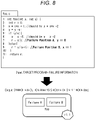
Fig. 8 is a view illustrating an example of the symbol execution analysis route according to the present embodiment. -
Fig. 9 is a view illustrating an example where failure information is integrated into target functions according to the present embodiment. -
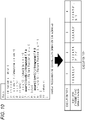
Fig. 10 is a view illustrating an example of an execution path according to the present embodiment. -
Fig. 11 is a view illustrating an example of a failure occurrence path according to the present embodiment. -
Fig. 12 is a view illustrating a flow example of the failure analysis support method according to the present embodiment. -
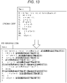
Fig. 13 is a view illustrating a code example according to the present embodiment. -
Fig. 14 is a view illustrating an example where a failure occurrence path is extracted according to the present embodiment. -
Fig. 15 is a view illustrating an example of a failure occurrence graph according to the present embodiment. -
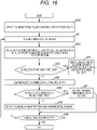
Fig. 16 is a view illustrating a flow example of the failure analysis support method according to the present embodiment. -
Fig. 17 is a view illustrating a flow example of the failure analysis support method according to the present embodiment. -
Fig. 18 is a view illustrating an example of the failure occurrence graph according to the present embodiment. -
Fig. 19A is a view illustrating an example of a failure relationship pattern according to the present embodiment. -
Fig. 19B is a view illustrating an example of the failure relationship pattern according to the present embodiment. -
Fig. 19C is a view illustrating an example of the failure relationship pattern according to the present embodiment. -
Fig. 20 is a view illustrating a calculation example of data correlation according to the present embodiment. -
Fig. 21 is a view illustrating a result display example according to the present embodiment. -
Fig. 22 is a view illustrating a result display example according to the present embodiment. - An embodiment of the present invention will be described in detail below using the drawings.
Fig. 1 is a configuration diagram of a system including a failureanalysis support device 100 according to the present embodiment. The failureanalysis support device 100 illustrated inFig. 1 is a computer capable of effectively avoiding duplication of analysis and correction with respect to a plurality of failures included in one program and supporting consistent correction. - As illustrated in
Fig. 1 , the failureanalysis support device 100 of the present embodiment is communicably connected to aterminal 5 connected via an appropriate interface 1 (or a communication line). Thus, these may be collectively referred to as a failureanalysis support system 10. - The failure
analysis support device 100 can also be said to be, for example, a server that provides a failure analysis support service operated by a business operator responsible for system development, a vendor supporting the business operator, or the like. - The failure
analysis support device 100 acquires information on asource code 125, a failure log 136, and a failurerelationship pattern definition 127 from theterminal 5 and stores various kinds ofinformation 130 to 134 generated on the basis of the information in astorage device 101 of the failureanalysis support device 100. Various kinds ofinformation 130 to 134 are, for example, afailure occurrence path 130, afailure occurrence graph 131, afailure variable definition 132, a failurerelationship pattern definition 133, and a failure relationship pattern instance 134. These will be described later. - The failure
analysis support device 100 includes functional units such as a failure occurrencepath regeneration unit 110, a failure occurrencegraph generation unit 111, a failure variabledefinition extraction unit 112, a failure relationship patterninstance search unit 113, and an analysisresult display unit 114. - Among these, the failure occurrence
path regeneration unit 110 is a functional unit that regeneratesoccurrence paths 130 of all failures on the basis of thesource code 125 obtained from theterminal 5. Thefailure occurrence paths 130 regenerated in this way are temporarily stored in amemory 103. - In addition, the failure occurrence
graph generation unit 111 is a functional unit that merges theoccurrence paths 130 of all the failures generated by the failure occurrencepath regeneration unit 110 described above and generates thefailure occurrence graph 131 in which information on variable definitions and usage in theoccurrence paths 130 is integrated. Thefailure occurrence graph 131 generated in this manner is temporarily stored in thememory 103. It is assumed that the failure occurrencegraph generation unit 111 uses the information on thevariable definition 132 and the usage in the failure data extracted by the failure variabledefinition extraction unit 112 for the integration. - The failure relationship pattern
instance search unit 113 is a functional unit that searches for an instance corresponding to the failurerelationship pattern definition 133 in thefailure occurrence graph 131 described above. The failurerelationship pattern definition 133 is thefailure relationship pattern 127 obtained from theterminal 5 and stored in thememory 103 and is a definition related to a relationship between failures. - In addition, the analysis
result display unit 114 serves as a functional unit that outputs a result of the search by the failure relationship patterninstance search unit 113 described above to theterminal 5 or a predetermined output interface. - On the other hand, the
terminal 5 is a terminal to be used by a person in charge of a business operator who uses the above-described failure analysis support service. Specifically, a personal computer, a smartphone, a tablet terminal, or the like, can be assumed. - The hardware configuration of the failure
analysis support device 100 of the present embodiment is as follows inFig. 2 . - In other words, the failure
analysis support device 100 includes thestorage device 101, thememory 103, thearithmetic device 104, and thecommunication device 105. - Among these, the
storage device 101 includes an appropriate non-volatile storage element such as a solid state drive (SSD) and a hard disk drive. - Further, the
memory 103 includes a volatile storage element such as a RAM. - In addition, the
arithmetic device 104 is a CPU that executes aprogram 102 stored in thestorage device 101 by reading the program to thememory 103, performs integrated control of the device itself and performs various kinds of determination, calculation, and control processing. Functional units obtained by executing theprogram 102 are the above-described failure occurrencepath regeneration unit 110, failure occurrencegraph generation unit 111, failure variabledefinition extraction unit 112, failure relationship patterninstance search unit 113, and analysisresult display unit 114. - Furthermore, the
communication device 105 is assumed to be a network interface card, or the like, that is connected to anetwork 1 and is responsible for communication processing with theterminal 5. - Note that, in a case where the failure
analysis support device 100 is standalone machine, it is preferable to further include an input device that receives key input or voice input from a user, and an output device such as a display that displays processing data. - In addition to the
program 102 for implementing functions necessary as the failure analysis support device of the present embodiment, at least thesource code 125, thefailure log 126, and the failurerelationship pattern definition 127 obtained from theterminal 5 are stored in thestorage device 101. - Hereinafter, actual procedure of the failure analysis support method in the present embodiment will be described with reference to the drawings. Various kinds of operation corresponding to the failure analysis support method which will be described below are implemented by a program to be read out to the memory, or the like, and executed by the failure
analysis support device 100. The program includes codes for performing various kinds of operation which will be described below. -
Fig. 3 is a view illustrating a flow example of the failure analysis support method according to the present embodiment. In this case, the failureanalysis support device 100 regenerates theoccurrence paths 130 of all failures on the basis of the source code 125 (seeFig. 4 ) (s1). - Subsequently, the failure
analysis support device 100 merges theoccurrence paths 130 of all the failures obtained in s1 and generates thefailure occurrence graph 131 in which information on thevariable definitions 132 and usage in theoccurrence paths 130 is integrated (s2). - In addition, the failure
analysis support device 100 searches for an instance corresponding to the failurerelationship pattern definition 133 in the above-described failure occurrence graph 131 (s3). - Further, the failure
analysis support device 100 outputs a result of the search in s3 to a device such as the terminal 5 (s4) and ends the processing. - Next, failure occurrence path regeneration processing by symbol execution constituting the failure occurrence path regeneration (s1) in the above-described main flow will be described with reference to
Figs. 5 to 11 . Here, the generation (s2) of thefailure occurrence graph 131 will also be described. - In this case, the failure occurrence
path regeneration unit 110 calculates a symbol execution analysis route that passes through all target functions, which are functions including failure positions, using a function calling relationship in the target source code 125 (s21). - Details of s21 will be illustrated in the example of the flow in
Fig. 7A and the symbol execution analysis route inFig. 7B . In the flow inFig. 7A , the failure occurrencepath regeneration unit 110 acquires a list of target functions that are functions including the failure positions (s211). - In addition, the failure occurrence
path regeneration unit 110 analyzes a function calling relationship (a relationship between a caller and a callee) between the target functions (s212). - Subsequently, the failure occurrence
path regeneration unit 110 searches for the shortest route connecting the target functions connected by the function calling relationship (s213). - In addition, the failure occurrence
path regeneration unit 110 assigns an execution order via an order of the callee and the caller to each function in the route for each route obtained in s213 (s214) and ends the processing. - Here, the description returns to the flow of
Fig. 6 . In this case, the failure occurrencepath regeneration unit 110 adds, for example, a code of "assert (!failure condition)" before statement of the failure positions (seeFig. 9 ) and integrates a failure condition into the target functions including them (s22). The positions of the code added here are referred to as an integrated failure position. - In addition, the failure occurrence
path regeneration unit 110 performs symbol execution from a function of the symbol execution analysis route with the smallest execution order (s23). Note that it is assumed that functions of different subroutes can be executed in parallel. Subsequently, the failure occurrencepath regeneration unit 110 stores information such as an execution path and a constraint in the storage device 101 (s24). An example of the execution path obtained by such symbol execution is illustrated inFig. 10 . - The failure occurrence
path regeneration unit 110 determines whether all the functions of the symbol execution analysis route have been executed (s25). - As a result of the above determination, in a case where not all the functions have been executed (s25: No), the failure occurrence
path regeneration unit 110 continues symbol execution of the function subsequent in the execution order (s26). - On the other hand, as a result of the above determination, in a case where all the functions have been executed (s25: Yes), the failure occurrence
path regeneration unit 110 acquires thefailure occurrence paths 130 that are execution paths ended by the integrated failure position (seeFig. 11 ) (s27) and ends the processing. - Next, failure occurrence path regeneration processing by log analysis constituting the failure occurrence path regeneration (s1) in the main flow described above will be described with reference to
Figs. 12 to 15 . Here, the generation (s2) of thefailure occurrence graph 131 will also be described. - In this case, the failure occurrence
path regeneration unit 110 searches thefailure log 126 for input values that become causes of the failures in the target functions (s32). Note that anoriginal source code 125 having a log function that outputs input values of a function to a log is assumed. - In addition, the failure occurrence
path regeneration unit 110 instruments (seeFig. 13 ) the target functions in order to record the execution trace including the executed statement and the information on the execution order (s32). - Subsequently, the failure occurrence
path regeneration unit 110 executes the above-described target functions using the input values that become the causes of the failures searched in s31 (s33). - In addition, the failure occurrence
path regeneration unit 110 extracts the failure occurrence paths from the log of the execution trace obtained in s33 (seeFig. 14 ) (s34) and ends the processing. - As described above, the failure
analysis support device 100, which has regenerated the failure occurrence paths, merges theoccurrence paths 130 of all the failures obtained in s1 and generates the failure occurrence graph 131 (seeFig. 15 ) in which the information on thevariable definitions 132 and the usage in theoccurrence paths 130 is integrated. - A basic structure of the
failure occurrence graph 131 includes nodes in which the definition information (statement) of the failure occurrence paths is set, information (such as failure IDs and path IDs) of the failure occurrence paths passing through the nodes, data flow information which is information on variable definitions and usage (predicate, calculate) in the respective nodes, and edges connecting the nodes in the order described in the failure occurrence paths. Note that the above-described variable receives a new value (initialization or value change) (def = {v}) and is used for calculation of the predicate (p-use = {v}). Also, the variable is used to calculate a value of another variable (c-use = {v}). - Next, processing of the instance search (s3) in the main flow described above will be described with reference to
Figs. 16 to 20 . - In this case, the failure relationship pattern
instance search unit 113 extracts failure data from thefailure occurrence graph 131 for each failure (s50). An example of such afailure occurrence graph 131 is illustrated inFig. 18 . Further, details of s50 are illustrated in the flow inFig. 17 . - In this case, the failure relationship pattern
instance search unit 113 adds a node (current node) corresponding to the integrated failure occurrence path (s501). - In addition, the failure relationship pattern
instance search unit 113 acquires variable use information, c-use, or p-use of the current node (s502). - Subsequently, the failure relationship pattern
instance search unit 113 determines whether the node has a plurality of pieces of variable use information and whether the node is the first node in the failure occurrence path (s503). - As a result of the above determination, in a case where the node is the first node (s503: No), the failure relationship pattern
instance search unit 113 causes the processing to transition to s506. - On the other hand, as a result of the above determination, in a case where the node is not the first node (s503: Yes), the failure relationship pattern
instance search unit 113 searches for the closest variable definition X in the failure occurrence path of the failure A defining x for each unprocessed variable x in the variable use information of the current node (s504). - Subsequently, the failure relationship pattern
instance search unit 113 adds X and edges labeled from X to x to the current node as a new node and new vertexes of the graph (s505). - In addition, the failure relationship pattern
instance search unit 113 determines whether there is a node in a list of nodes under consideration (s506). - As a result of the above-described determination, in a case where there is a node in the list (s506: Yes), the failure relationship pattern
instance search unit 113 selects a node from the list of nodes under consideration, sets the node as the current investigation target node (s507) and returns the processing to s502. - On the other hand, as a result of the above-described determination, in a case where it is determined that there is no node (s506: No), the failure relationship pattern
instance search unit 113 ends the processing. - Here, the description returns to the flow in
Fig. 16 . The failure relationship patterninstance search unit 113 acquires an unprocessed failure pair (s51). - Subsequently, the failure relationship pattern
instance search unit 113 collates a result of merging the variable definitions and the like of the failures in the failure pair with the failurerelationship pattern definition 127 to specify a pattern (s52). - In addition, the failure relationship pattern
instance search unit 113 determines whether the failures of the pair have a shared edge (s53). - As a result of the above determination, in a case where there is a shared edge (s53: Yes), the failure relationship pattern
instance search unit 113 specifies that the pair has a data-dependent failure relationship pattern (Fig. 19A ) (s54) and causes the processing to transition to s59. Note that for the pair, data correlation between the failures is calculated on the basis of, for example, a data correlation calculation formula 201 (Fig. 20 ). - On the other hand, as a result of the above determination, in a case where there is no shared edge (s53: No), the failure relationship pattern
instance search unit 113 compares the failure occurrence paths of the failures of the pair (s55). - Subsequently, the failure relationship pattern
instance search unit 113 determines whether the failure occurrence paths include a shared node (s56). - As a result of the above-described determination, in a case where the failure occurrence paths include the shared node (s56: Yes), the failure relationship pattern
instance search unit 113 specifies that the pair has a control-dependent failure relationship pattern (Fig. 19C ) (s57) and causes the processing to transition to s59. On the other hand, in a case where the failure occurrence paths do not include the shared node as a result of the above-described determination (s56: No), the failure relationship patterninstance search unit 113 specifies that the pair has a failure relationship pattern having an independent relationship (s58). - In addition, the failure relationship pattern
instance search unit 113 determines whether all the pairs have been processed (s59). - As a result of the above-described determination, in a case where all the pairs have not been processed (s59: No), the failure relationship pattern
instance search unit 113 returns the processing to s51. On the other hand, as a result of the above-described determination, in a case where all the pairs have been processed (s56: Yes), the failure relationship patterninstance search unit 113 ends the processing. - It is preferable that the analysis
result display unit 114 in the failureanalysis support device 100 of the present embodiment distribute data of thefailure occurrence graph 131 obtained so far to, for example, theterminal 5 to display (Fig. 21 ). Similarly, as described above, the source code (Fig. 22 ) in which all the failure occurrence paths are merged may be distributed to theterminal 5 and displayed. - Although the best mode, and the like, for carrying out the present invention have been specifically described above, the present invention is not limited thereto, and various modifications can be made without departing from the gist thereof.
- According to this embodiment, it is possible to effectively avoid duplication of analysis and correction and to support consistent correction for a plurality of failures included in one program.
- The description of the present specification reveals at least the following. In other words, in the failure analysis support device of the present embodiment, when generating the failure occurrence graph, the arithmetic device may set definition information on variables of the occurrence paths of the failures to nodes, set usage of the variables set to the nodes as a data flow and connect the nodes by edges along an order described in the occurrence paths to thereby generate the failure occurrence graph.
- According to this, it is possible to efficiently generate paths indicating a failure occurrence state. As a result, it is possible to more effectively avoid duplication of analysis and correction and to support consistent correction for a plurality of failures included in one program.
- In the failure analysis support device according to the present embodiment, when searching for the instance, the arithmetic device may execute processing of extracting information including definitions of the variables of the failures, graph elements to be used to describe the definitions of the variables, and usage of all variables appearing in a failure state from the failure occurrence graph for each failure, processing of specifying an unprocessed failure pair, comparing a result of merging the definitions of the variables of failures in the failure pair and the graph elements with the failure relationship pattern and determining a corresponding failure relationship pattern, processing of determining whether the definitions of the variables in the failure pair and the graph elements include a shared edge, processing of comparing occurrence paths of the failures in the failure pair in a case where the definitions of the variables of the failure pair and the graph elements do not include the shared edge as a result of determination regarding the shared edge, determining whether the occurrence paths include a shared node, and specifying that the failures are independent of each other in a case where the occurrence paths do not include the shared node, processing of calculating data correlation between the failures in the failure pair in a case where the definitions of the variables in the failure pair and the graph elements include the shared edge as a result of determination regarding the shared edge, and processing of specifying that the failures have a control-dependent failure relationship in a case where the occurrence paths include the shared node as a result of determination regarding the shared node.
- This enables targets to be analyzed and examined to be efficiently specified on the basis of the relationship between the failure occurrence elements. As a result, it is possible to more effectively avoid duplication of analysis and correction and to support consistent correction for a plurality of failures included in one program.
- In the failure analysis support method of the present embodiment, when generating the failure occurrence graph, the information processing device may set definition information on variables of occurrence paths of failures to nodes, set usage of the variables set to the nodes as a data flow, and connect the nodes by edges along an order described in the occurrence paths to thereby generate the failure occurrence graph.
- In the failure analysis support method according to the present embodiment, the information processing device may execute, when searching for the instance, processing of extracting information on definitions of the variables of failures, graph elements to be used to describe the definitions of the variables, and usage of all variables appearing in a failure state from the failure occurrence graph for each failure, processing of specifying an unprocessed failure pair, comparing a result of merging the definitions of the variables of failures in the failure pair and the graph elements with the failure relationship pattern and determining a corresponding failure relationship pattern, processing of determining whether the definitions of the variables in the failure pair and the graph elements include a shared edge, processing of comparing occurrence paths of the failures in the failure pair in a case where the definitions of the variables in the failure pair and the graph elements do not include the shared edge as a result of determination regarding the shared edge, determining whether the occurrence paths include a shared node, and specifying that the failures are independent of each other in a case where the occurrence paths do not include the shared node, processing of calculating data correlation between the failures in the failure pair in a case where the definitions of the variables in the failure pair and the graph elements include the shared edge as a result of determination regarding the shared edge, and processing of specifying that the failures have a control-dependent failure relationship in a case where the occurrence paths include the shared node as a result of determination regarding the shared node.
Claims (6)
- A failure analysis support device (100) comprising:a storage device (101) configured to store a source code of software to be processed; andan arithmetic device (104) configured to execute processing of regenerating occurrence paths of all failures on a basis of the source code, processing of merging the occurrence paths of all the failures and generating a failure occurrence graph in which information on variable definitions and usage in the occurrence paths is integrated, processing of searching for an instance corresponding to a failure relationship pattern defined in advance for a relationship between failures in the failure occurrence graph, and processing of outputting a result of the search to a predetermined device.
- The failure analysis support device (100) according to claim 1, wherein when generating the failure occurrence graph, the arithmetic device (104) sets definition information on variables of the occurrence paths of the failures to nodes, sets usage of the variables set to the nodes as a data flow and connects the nodes by edges along an order described in the occurrence paths to thereby generate the failure occurrence graph.
- The failure analysis support device (100) according to claim 2, wherein when searching for the instance, the arithmetic device (104) executesprocessing of extracting information including definitions of the variables of the failures, graph elements to be used to describe the definitions of the variables, and usage of all variables appearing in a failure state from the failure occurrence graph for each failure,processing of specifying an unprocessed failure pair, comparing a result of merging the definitions of the variables of failures in the failure pair and the graph elements with the failure relationship pattern and determining a corresponding failure relationship pattern,processing of determining whether the definitions of the variables in the failure pair and the graph elements include a shared edge,processing of comparing occurrence paths of the failures in the failure pair in a case where the definitions of the variables of the failure pair and the graph elements do not include the shared edge as a result of determination regarding the shared edge, determining whether the occurrence paths include a shared node, and specifying that the failures are independent of each other in a case where the occurrence paths do not include the shared node,processing of calculating data correlation between the failures in the failure pair in a case where the definitions of the variables in the failure pair and the graph elements include the shared edge as a result of determination regarding the shared edge, andprocessing of specifying that the failures have a control-dependent failure relationship in a case where the occurrence paths include the shared node as a result of determination regarding the shared node.
- A failure analysis support method, wherein an information processing devicestores a source code of software to be processed in a storage device (101), andexecutes processing of regenerating occurrence paths of all failures on a basis of the source code, processing of merging the occurrence paths of all the failures to generate a failure occurrence graph in which information of variable definitions and usage in the occurrence paths is integrated, processing of searching for an instance corresponding to a failure relationship pattern defined in advance for a relationship between failures in the failure occurrence graph, and processing of outputting a result of the search to a predetermined device.
- The failure analysis support method according to claim 4, wherein when generating the failure occurrence graph, the information processing device sets definition information on variables of occurrence paths of failures to nodes, sets usage of the variables set to the nodes as a data flow, and connects the nodes by edges along an order described in the occurrence paths to thereby generate the failure occurrence graph.
- The failure analysis support method according to claim 5, wherein the information processing device executes, when searching for the instance,processing of extracting information on definitions of the variables of failures, graph elements to be used to describe the definitions of the variables, and usage of all variables appearing in a failure state from the failure occurrence graph for each failure,processing of specifying an unprocessed failure pair, comparing a result of merging the definitions of the variables of failures in the failure pair and the graph elements with the failure relationship pattern and determining a corresponding failure relationship pattern,processing of determining whether the definitions of the variables in the failure pair and the graph elements include a shared edge,processing of comparing occurrence paths of the failures in the failure pair in a case where the definitions of the variables in the failure pair and the graph elements do not include the shared edge as a result of determination regarding the shared edge, determining whether the occurrence paths include a shared node, and specifying that the failures are independent of each other in a case where the occurrence paths do not include the shared node,processing of calculating data correlation between the failures in the failure pair in a case where the definitions of the variables in the failure pair and the graph elements include the shared edge as a result of determination regarding the shared edge, andprocessing of specifying that the failures have a control-dependent failure relationship in a case where the occurrence paths include the shared node as a result of determination regarding the shared node.
Applications Claiming Priority (1)
| Application Number | Priority Date | Filing Date | Title |
|---|---|---|---|
| JP2021114875A JP7664779B2 (en) | 2021-07-12 | 2021-07-12 | Fault analysis support device and fault analysis support method |
Publications (2)
| Publication Number | Publication Date |
|---|---|
| EP4120085A1 true EP4120085A1 (en) | 2023-01-18 |
| EP4120085B1 EP4120085B1 (en) | 2025-01-22 |
Family
ID=82547637
Family Applications (1)
| Application Number | Title | Priority Date | Filing Date |
|---|---|---|---|
| EP22182876.7A Active EP4120085B1 (en) | 2021-07-12 | 2022-07-04 | Failure analysis support device and failure analysis support method |
Country Status (2)
| Country | Link |
|---|---|
| EP (1) | EP4120085B1 (en) |
| JP (1) | JP7664779B2 (en) |
Citations (5)
| Publication number | Priority date | Publication date | Assignee | Title |
|---|---|---|---|---|
| JP2012128727A (en) | 2010-12-16 | 2012-07-05 | Toyota Infotechnology Center Co Ltd | Reliability evaluation method and apparatus for software component |
| US20120304153A1 (en) * | 2011-05-26 | 2012-11-29 | Oracle International Corporation | Context-sensitive analysis framework using value flows |
| US20130031531A1 (en) * | 2011-07-27 | 2013-01-31 | Oracle International Corporation | Method and system for performing backward-driven path-sensitive dataflow analysis |
| CN106294156A (en) * | 2016-08-11 | 2017-01-04 | 北京邮电大学 | A kind of static code fault detection analysis method and device |
| JP2021114875A (en) | 2020-01-21 | 2021-08-05 | 株式会社沖データ | Load control device and image forming device |
Family Cites Families (7)
| Publication number | Priority date | Publication date | Assignee | Title |
|---|---|---|---|---|
| JP2001249828A (en) * | 1999-12-28 | 2001-09-14 | Toshiba Lsi System Support Kk | Information processing device, computer-readable storage medium storing defect analysis program, defect analysis method, and application program development support system |
| JP5125938B2 (en) * | 2008-09-24 | 2013-01-23 | 富士通株式会社 | Bug detection support program, similar syntax identification information list output program, bug detection support device, and bug detection support method |
| JP5303795B2 (en) * | 2010-06-02 | 2013-10-02 | 株式会社日立製作所 | Application analysis method, analysis system, and analysis program |
| US10599852B2 (en) * | 2014-08-15 | 2020-03-24 | Securisea, Inc. | High performance software vulnerabilities detection system and methods |
| JP6369269B2 (en) * | 2014-10-01 | 2018-08-08 | 日本電気株式会社 | Verification support apparatus, verification support method, and computer program |
| JP6576873B2 (en) * | 2016-04-08 | 2019-09-18 | 株式会社日立製作所 | Job net verification apparatus and job net verification method |
| WO2018003107A1 (en) * | 2016-07-01 | 2018-01-04 | 株式会社日立製作所 | Control device |
-
2021
- 2021-07-12 JP JP2021114875A patent/JP7664779B2/en active Active
-
2022
- 2022-07-04 EP EP22182876.7A patent/EP4120085B1/en active Active
Patent Citations (5)
| Publication number | Priority date | Publication date | Assignee | Title |
|---|---|---|---|---|
| JP2012128727A (en) | 2010-12-16 | 2012-07-05 | Toyota Infotechnology Center Co Ltd | Reliability evaluation method and apparatus for software component |
| US20120304153A1 (en) * | 2011-05-26 | 2012-11-29 | Oracle International Corporation | Context-sensitive analysis framework using value flows |
| US20130031531A1 (en) * | 2011-07-27 | 2013-01-31 | Oracle International Corporation | Method and system for performing backward-driven path-sensitive dataflow analysis |
| CN106294156A (en) * | 2016-08-11 | 2017-01-04 | 北京邮电大学 | A kind of static code fault detection analysis method and device |
| JP2021114875A (en) | 2020-01-21 | 2021-08-05 | 株式会社沖データ | Load control device and image forming device |
Also Published As
| Publication number | Publication date |
|---|---|
| JP7664779B2 (en) | 2025-04-18 |
| JP2023011182A (en) | 2023-01-24 |
| EP4120085B1 (en) | 2025-01-22 |
Similar Documents
| Publication | Publication Date | Title |
|---|---|---|
| US8819642B2 (en) | Method and system for generating and processing black box test cases | |
| US9921948B2 (en) | Software commit risk level | |
| US10943181B2 (en) | Just in time classifier training | |
| CN114116496A (en) | Automatic testing method, device, equipment and medium | |
| CN113227971A (en) | Real-time application error identification and mitigation | |
| JP2006031109A (en) | Management system and management method | |
| CN110032505B (en) | Software quality determination apparatus and method, and non-transitory computer readable medium | |
| US20100077382A1 (en) | Computer-readable recording medium string a bug detection support program, similar structure identification information list output program, bug detection support apparatus, and bug detection support method | |
| CN115587048A (en) | Regression testing method, terminal device and computer readable storage medium | |
| CN119645483A (en) | Open source component vulnerability upgrade compatibility analysis method and electronic device | |
| JP2019101581A (en) | Software quality determination device, software quality determination method, and software quality determination program | |
| JP6451417B2 (en) | Debug support device, debug support system, debug support method, and debug support program | |
| EP4120085B1 (en) | Failure analysis support device and failure analysis support method | |
| JP5900212B2 (en) | Test data generation apparatus, program, and method | |
| US8510693B2 (en) | Changing abstraction level of portion of circuit design during verification | |
| CN119396719B (en) | Software efficient test method and system based on artificial intelligence | |
| CN118897668B (en) | Public code library management method, system, equipment and medium | |
| JP5516277B2 (en) | Test case relation extraction method, test case relation extraction device, and test case relation extraction program | |
| JP5755861B2 (en) | Test case generation apparatus, test case generation method, and test case generation program | |
| CN113297038B (en) | Monitoring and data processing method, device and equipment, monitoring system and data center | |
| WO2004068347A1 (en) | Method and apparatus for categorising test scripts | |
| CN114218119A (en) | Software abnormal flow testing method, system, terminal and storage medium | |
| US20140181597A1 (en) | Systems and methods for debugging model based message sequences | |
| CN120448267B (en) | Test case priority sequence recommendation method and system based on path | |
| JP2019185623A (en) | Device and method for generating information on operation difference between web browsers |
Legal Events
| Date | Code | Title | Description |
|---|---|---|---|
| PUAI | Public reference made under article 153(3) epc to a published international application that has entered the european phase |
Free format text: ORIGINAL CODE: 0009012 |
|
| STAA | Information on the status of an ep patent application or granted ep patent |
Free format text: STATUS: REQUEST FOR EXAMINATION WAS MADE |
|
| 17P | Request for examination filed |
Effective date: 20220704 |
|
| AK | Designated contracting states |
Kind code of ref document: A1 Designated state(s): AL AT BE BG CH CY CZ DE DK EE ES FI FR GB GR HR HU IE IS IT LI LT LU LV MC MK MT NL NO PL PT RO RS SE SI SK SM TR |
|
| STAA | Information on the status of an ep patent application or granted ep patent |
Free format text: STATUS: EXAMINATION IS IN PROGRESS |
|
| 17Q | First examination report despatched |
Effective date: 20231127 |
|
| GRAP | Despatch of communication of intention to grant a patent |
Free format text: ORIGINAL CODE: EPIDOSNIGR1 |
|
| STAA | Information on the status of an ep patent application or granted ep patent |
Free format text: STATUS: GRANT OF PATENT IS INTENDED |
|
| INTG | Intention to grant announced |
Effective date: 20240911 |
|
| GRAS | Grant fee paid |
Free format text: ORIGINAL CODE: EPIDOSNIGR3 |
|
| GRAA | (expected) grant |
Free format text: ORIGINAL CODE: 0009210 |
|
| STAA | Information on the status of an ep patent application or granted ep patent |
Free format text: STATUS: THE PATENT HAS BEEN GRANTED |
|
| AK | Designated contracting states |
Kind code of ref document: B1 Designated state(s): AL AT BE BG CH CY CZ DE DK EE ES FI FR GB GR HR HU IE IS IT LI LT LU LV MC MK MT NL NO PL PT RO RS SE SI SK SM TR |
|
| REG | Reference to a national code |
Ref country code: GB Ref legal event code: FG4D |
|
| REG | Reference to a national code |
Ref country code: CH Ref legal event code: EP |
|
| REG | Reference to a national code |
Ref country code: IE Ref legal event code: FG4D |
|
| REG | Reference to a national code |
Ref country code: DE Ref legal event code: R096 Ref document number: 602022009737 Country of ref document: DE |
|
| REG | Reference to a national code |
Ref country code: NL Ref legal event code: MP Effective date: 20250122 |
|
| PG25 | Lapsed in a contracting state [announced via postgrant information from national office to epo] |
Ref country code: NL Free format text: LAPSE BECAUSE OF FAILURE TO SUBMIT A TRANSLATION OF THE DESCRIPTION OR TO PAY THE FEE WITHIN THE PRESCRIBED TIME-LIMIT Effective date: 20250122 |
|
| PG25 | Lapsed in a contracting state [announced via postgrant information from national office to epo] |
Ref country code: RS Free format text: LAPSE BECAUSE OF FAILURE TO SUBMIT A TRANSLATION OF THE DESCRIPTION OR TO PAY THE FEE WITHIN THE PRESCRIBED TIME-LIMIT Effective date: 20250422 |
|
| PG25 | Lapsed in a contracting state [announced via postgrant information from national office to epo] |
Ref country code: FI Free format text: LAPSE BECAUSE OF FAILURE TO SUBMIT A TRANSLATION OF THE DESCRIPTION OR TO PAY THE FEE WITHIN THE PRESCRIBED TIME-LIMIT Effective date: 20250122 |
|
| PG25 | Lapsed in a contracting state [announced via postgrant information from national office to epo] |
Ref country code: PL Free format text: LAPSE BECAUSE OF FAILURE TO SUBMIT A TRANSLATION OF THE DESCRIPTION OR TO PAY THE FEE WITHIN THE PRESCRIBED TIME-LIMIT Effective date: 20250122 |
|
| PG25 | Lapsed in a contracting state [announced via postgrant information from national office to epo] |
Ref country code: ES Free format text: LAPSE BECAUSE OF FAILURE TO SUBMIT A TRANSLATION OF THE DESCRIPTION OR TO PAY THE FEE WITHIN THE PRESCRIBED TIME-LIMIT Effective date: 20250122 |
|
| REG | Reference to a national code |
Ref country code: LT Ref legal event code: MG9D |
|
| PG25 | Lapsed in a contracting state [announced via postgrant information from national office to epo] |
Ref country code: NO Free format text: LAPSE BECAUSE OF FAILURE TO SUBMIT A TRANSLATION OF THE DESCRIPTION OR TO PAY THE FEE WITHIN THE PRESCRIBED TIME-LIMIT Effective date: 20250422 Ref country code: IS Free format text: LAPSE BECAUSE OF FAILURE TO SUBMIT A TRANSLATION OF THE DESCRIPTION OR TO PAY THE FEE WITHIN THE PRESCRIBED TIME-LIMIT Effective date: 20250522 |
|
| REG | Reference to a national code |
Ref country code: AT Ref legal event code: MK05 Ref document number: 1761968 Country of ref document: AT Kind code of ref document: T Effective date: 20250122 |
|
| PG25 | Lapsed in a contracting state [announced via postgrant information from national office to epo] |
Ref country code: HR Free format text: LAPSE BECAUSE OF FAILURE TO SUBMIT A TRANSLATION OF THE DESCRIPTION OR TO PAY THE FEE WITHIN THE PRESCRIBED TIME-LIMIT Effective date: 20250122 |
|
| PG25 | Lapsed in a contracting state [announced via postgrant information from national office to epo] |
Ref country code: LV Free format text: LAPSE BECAUSE OF FAILURE TO SUBMIT A TRANSLATION OF THE DESCRIPTION OR TO PAY THE FEE WITHIN THE PRESCRIBED TIME-LIMIT Effective date: 20250122 Ref country code: PT Free format text: LAPSE BECAUSE OF FAILURE TO SUBMIT A TRANSLATION OF THE DESCRIPTION OR TO PAY THE FEE WITHIN THE PRESCRIBED TIME-LIMIT Effective date: 20250522 |
|
| PG25 | Lapsed in a contracting state [announced via postgrant information from national office to epo] |
Ref country code: BG Free format text: LAPSE BECAUSE OF FAILURE TO SUBMIT A TRANSLATION OF THE DESCRIPTION OR TO PAY THE FEE WITHIN THE PRESCRIBED TIME-LIMIT Effective date: 20250122 Ref country code: GR Free format text: LAPSE BECAUSE OF FAILURE TO SUBMIT A TRANSLATION OF THE DESCRIPTION OR TO PAY THE FEE WITHIN THE PRESCRIBED TIME-LIMIT Effective date: 20250423 |
|
| PG25 | Lapsed in a contracting state [announced via postgrant information from national office to epo] |
Ref country code: AT Free format text: LAPSE BECAUSE OF FAILURE TO SUBMIT A TRANSLATION OF THE DESCRIPTION OR TO PAY THE FEE WITHIN THE PRESCRIBED TIME-LIMIT Effective date: 20250122 |
|
| PG25 | Lapsed in a contracting state [announced via postgrant information from national office to epo] |
Ref country code: SE Free format text: LAPSE BECAUSE OF FAILURE TO SUBMIT A TRANSLATION OF THE DESCRIPTION OR TO PAY THE FEE WITHIN THE PRESCRIBED TIME-LIMIT Effective date: 20250122 |
|
| PG25 | Lapsed in a contracting state [announced via postgrant information from national office to epo] |
Ref country code: SM Free format text: LAPSE BECAUSE OF FAILURE TO SUBMIT A TRANSLATION OF THE DESCRIPTION OR TO PAY THE FEE WITHIN THE PRESCRIBED TIME-LIMIT Effective date: 20250122 |
|
| PG25 | Lapsed in a contracting state [announced via postgrant information from national office to epo] |
Ref country code: DK Free format text: LAPSE BECAUSE OF FAILURE TO SUBMIT A TRANSLATION OF THE DESCRIPTION OR TO PAY THE FEE WITHIN THE PRESCRIBED TIME-LIMIT Effective date: 20250122 |
|
| PGFP | Annual fee paid to national office [announced via postgrant information from national office to epo] |
Ref country code: DE Payment date: 20250723 Year of fee payment: 4 |
|
| PG25 | Lapsed in a contracting state [announced via postgrant information from national office to epo] |
Ref country code: IT Free format text: LAPSE BECAUSE OF FAILURE TO SUBMIT A TRANSLATION OF THE DESCRIPTION OR TO PAY THE FEE WITHIN THE PRESCRIBED TIME-LIMIT Effective date: 20250122 |
|
| PG25 | Lapsed in a contracting state [announced via postgrant information from national office to epo] |
Ref country code: CZ Free format text: LAPSE BECAUSE OF FAILURE TO SUBMIT A TRANSLATION OF THE DESCRIPTION OR TO PAY THE FEE WITHIN THE PRESCRIBED TIME-LIMIT Effective date: 20250122 Ref country code: EE Free format text: LAPSE BECAUSE OF FAILURE TO SUBMIT A TRANSLATION OF THE DESCRIPTION OR TO PAY THE FEE WITHIN THE PRESCRIBED TIME-LIMIT Effective date: 20250122 |
|
| REG | Reference to a national code |
Ref country code: DE Ref legal event code: R097 Ref document number: 602022009737 Country of ref document: DE |
|
| PG25 | Lapsed in a contracting state [announced via postgrant information from national office to epo] |
Ref country code: RO Free format text: LAPSE BECAUSE OF FAILURE TO SUBMIT A TRANSLATION OF THE DESCRIPTION OR TO PAY THE FEE WITHIN THE PRESCRIBED TIME-LIMIT Effective date: 20250122 |
|
| PG25 | Lapsed in a contracting state [announced via postgrant information from national office to epo] |
Ref country code: SK Free format text: LAPSE BECAUSE OF FAILURE TO SUBMIT A TRANSLATION OF THE DESCRIPTION OR TO PAY THE FEE WITHIN THE PRESCRIBED TIME-LIMIT Effective date: 20250122 |
|
| PLBE | No opposition filed within time limit |
Free format text: ORIGINAL CODE: 0009261 |
|
| STAA | Information on the status of an ep patent application or granted ep patent |
Free format text: STATUS: NO OPPOSITION FILED WITHIN TIME LIMIT |
|
| REG | Reference to a national code |
Ref country code: CH Ref legal event code: L10 Free format text: ST27 STATUS EVENT CODE: U-0-0-L10-L00 (AS PROVIDED BY THE NATIONAL OFFICE) Effective date: 20251203 |
|
| 26N | No opposition filed |
Effective date: 20251023 |
|
| REG | Reference to a national code |
Ref country code: CH Ref legal event code: H13 Free format text: ST27 STATUS EVENT CODE: U-0-0-H10-H13 (AS PROVIDED BY THE NATIONAL OFFICE) Effective date: 20260224 |
|
| PG25 | Lapsed in a contracting state [announced via postgrant information from national office to epo] |
Ref country code: LU Free format text: LAPSE BECAUSE OF NON-PAYMENT OF DUE FEES Effective date: 20250704 |
|
| REG | Reference to a national code |
Ref country code: BE Ref legal event code: MM Effective date: 20250731 |
|
| PG25 | Lapsed in a contracting state [announced via postgrant information from national office to epo] |
Ref country code: BE Free format text: LAPSE BECAUSE OF NON-PAYMENT OF DUE FEES Effective date: 20250731 |
|
| PG25 | Lapsed in a contracting state [announced via postgrant information from national office to epo] |
Ref country code: FR Free format text: LAPSE BECAUSE OF NON-PAYMENT OF DUE FEES Effective date: 20250731 |
|
| PG25 | Lapsed in a contracting state [announced via postgrant information from national office to epo] |
Ref country code: CH Free format text: LAPSE BECAUSE OF NON-PAYMENT OF DUE FEES Effective date: 20250731 |