EP4120030A1 - Electronic device, and interaction method and apparatus - Google Patents
Electronic device, and interaction method and apparatus Download PDFInfo
- Publication number
- EP4120030A1 EP4120030A1 EP21780676.9A EP21780676A EP4120030A1 EP 4120030 A1 EP4120030 A1 EP 4120030A1 EP 21780676 A EP21780676 A EP 21780676A EP 4120030 A1 EP4120030 A1 EP 4120030A1
- Authority
- EP
- European Patent Office
- Prior art keywords
- rotating member
- angle
- infrared
- rotation
- module
- Prior art date
- Legal status (The legal status is an assumption and is not a legal conclusion. Google has not performed a legal analysis and makes no representation as to the accuracy of the status listed.)
- Pending
Links
Images


Classifications
-
- G—PHYSICS
- G01—MEASURING; TESTING
- G01P—MEASURING LINEAR OR ANGULAR SPEED, ACCELERATION, DECELERATION, OR SHOCK; INDICATING PRESENCE, ABSENCE, OR DIRECTION, OF MOVEMENT
- G01P13/00—Indicating or recording presence, absence, or direction, of movement
- G01P13/02—Indicating direction only, e.g. by weather vane
- G01P13/04—Indicating positive or negative direction of a linear movement or clockwise or anti-clockwise direction of a rotational movement
-
- G—PHYSICS
- G01—MEASURING; TESTING
- G01S—RADIO DIRECTION-FINDING; RADIO NAVIGATION; DETERMINING DISTANCE OR VELOCITY BY USE OF RADIO WAVES; LOCATING OR PRESENCE-DETECTING BY USE OF THE REFLECTION OR RERADIATION OF RADIO WAVES; ANALOGOUS ARRANGEMENTS USING OTHER WAVES
- G01S7/00—Details of systems according to groups G01S13/00, G01S15/00, G01S17/00
- G01S7/48—Details of systems according to groups G01S13/00, G01S15/00, G01S17/00 of systems according to group G01S17/00
- G01S7/481—Constructional features, e.g. arrangements of optical elements
- G01S7/4817—Constructional features, e.g. arrangements of optical elements relating to scanning
-
- G—PHYSICS
- G04—HOROLOGY
- G04B—MECHANICALLY-DRIVEN CLOCKS OR WATCHES; MECHANICAL PARTS OF CLOCKS OR WATCHES IN GENERAL; TIME PIECES USING THE POSITION OF THE SUN, MOON OR STARS
- G04B39/00—Watch crystals; Fastening or sealing of crystals; Clock glasses
-
- G—PHYSICS
- G01—MEASURING; TESTING
- G01B—MEASURING LENGTH, THICKNESS OR SIMILAR LINEAR DIMENSIONS; MEASURING ANGLES; MEASURING AREAS; MEASURING IRREGULARITIES OF SURFACES OR CONTOURS
- G01B11/00—Measuring arrangements characterised by the use of optical techniques
- G01B11/26—Measuring arrangements characterised by the use of optical techniques for measuring angles or tapers; for testing the alignment of axes
-
- G—PHYSICS
- G01—MEASURING; TESTING
- G01D—MEASURING NOT SPECIALLY ADAPTED FOR A SPECIFIC VARIABLE; ARRANGEMENTS FOR MEASURING TWO OR MORE VARIABLES NOT COVERED IN A SINGLE OTHER SUBCLASS; TARIFF METERING APPARATUS; MEASURING OR TESTING NOT OTHERWISE PROVIDED FOR
- G01D5/00—Mechanical means for transferring the output of a sensing member; Means for converting the output of a sensing member to another variable where the form or nature of the sensing member does not constrain the means for converting; Transducers not specially adapted for a specific variable
- G01D5/26—Mechanical means for transferring the output of a sensing member; Means for converting the output of a sensing member to another variable where the form or nature of the sensing member does not constrain the means for converting; Transducers not specially adapted for a specific variable characterised by optical transfer means, i.e. using infrared, visible, or ultraviolet light
- G01D5/32—Mechanical means for transferring the output of a sensing member; Means for converting the output of a sensing member to another variable where the form or nature of the sensing member does not constrain the means for converting; Transducers not specially adapted for a specific variable characterised by optical transfer means, i.e. using infrared, visible, or ultraviolet light with attenuation or whole or partial obturation of beams of light
- G01D5/34—Mechanical means for transferring the output of a sensing member; Means for converting the output of a sensing member to another variable where the form or nature of the sensing member does not constrain the means for converting; Transducers not specially adapted for a specific variable characterised by optical transfer means, i.e. using infrared, visible, or ultraviolet light with attenuation or whole or partial obturation of beams of light the beams of light being detected by photocells
-
- G—PHYSICS
- G01—MEASURING; TESTING
- G01D—MEASURING NOT SPECIALLY ADAPTED FOR A SPECIFIC VARIABLE; ARRANGEMENTS FOR MEASURING TWO OR MORE VARIABLES NOT COVERED IN A SINGLE OTHER SUBCLASS; TARIFF METERING APPARATUS; MEASURING OR TESTING NOT OTHERWISE PROVIDED FOR
- G01D5/00—Mechanical means for transferring the output of a sensing member; Means for converting the output of a sensing member to another variable where the form or nature of the sensing member does not constrain the means for converting; Transducers not specially adapted for a specific variable
- G01D5/26—Mechanical means for transferring the output of a sensing member; Means for converting the output of a sensing member to another variable where the form or nature of the sensing member does not constrain the means for converting; Transducers not specially adapted for a specific variable characterised by optical transfer means, i.e. using infrared, visible, or ultraviolet light
- G01D5/32—Mechanical means for transferring the output of a sensing member; Means for converting the output of a sensing member to another variable where the form or nature of the sensing member does not constrain the means for converting; Transducers not specially adapted for a specific variable characterised by optical transfer means, i.e. using infrared, visible, or ultraviolet light with attenuation or whole or partial obturation of beams of light
- G01D5/34—Mechanical means for transferring the output of a sensing member; Means for converting the output of a sensing member to another variable where the form or nature of the sensing member does not constrain the means for converting; Transducers not specially adapted for a specific variable characterised by optical transfer means, i.e. using infrared, visible, or ultraviolet light with attenuation or whole or partial obturation of beams of light the beams of light being detected by photocells
- G01D5/347—Mechanical means for transferring the output of a sensing member; Means for converting the output of a sensing member to another variable where the form or nature of the sensing member does not constrain the means for converting; Transducers not specially adapted for a specific variable characterised by optical transfer means, i.e. using infrared, visible, or ultraviolet light with attenuation or whole or partial obturation of beams of light the beams of light being detected by photocells using displacement encoding scales
- G01D5/34776—Absolute encoders with analogue or digital scales
-
- G—PHYSICS
- G01—MEASURING; TESTING
- G01P—MEASURING LINEAR OR ANGULAR SPEED, ACCELERATION, DECELERATION, OR SHOCK; INDICATING PRESENCE, ABSENCE, OR DIRECTION, OF MOVEMENT
- G01P13/00—Indicating or recording presence, absence, or direction, of movement
- G01P13/02—Indicating direction only, e.g. by weather vane
-
- G—PHYSICS
- G01—MEASURING; TESTING
- G01S—RADIO DIRECTION-FINDING; RADIO NAVIGATION; DETERMINING DISTANCE OR VELOCITY BY USE OF RADIO WAVES; LOCATING OR PRESENCE-DETECTING BY USE OF THE REFLECTION OR RERADIATION OF RADIO WAVES; ANALOGOUS ARRANGEMENTS USING OTHER WAVES
- G01S7/00—Details of systems according to groups G01S13/00, G01S15/00, G01S17/00
- G01S7/48—Details of systems according to groups G01S13/00, G01S15/00, G01S17/00 of systems according to group G01S17/00
- G01S7/481—Constructional features, e.g. arrangements of optical elements
- G01S7/4814—Constructional features, e.g. arrangements of optical elements of transmitters alone
-
- G—PHYSICS
- G04—HOROLOGY
- G04C—ELECTROMECHANICAL CLOCKS OR WATCHES
- G04C3/00—Electromechanical clocks or watches independent of other time-pieces and in which the movement is maintained by electric means
- G04C3/001—Electromechanical switches for setting or display
-
- G—PHYSICS
- G04—HOROLOGY
- G04G—ELECTRONIC TIME-PIECES
- G04G21/00—Input or output devices integrated in time-pieces
-
- G—PHYSICS
- G06—COMPUTING OR CALCULATING; COUNTING
- G06F—ELECTRIC DIGITAL DATA PROCESSING
- G06F3/00—Input arrangements for transferring data to be processed into a form capable of being handled by the computer; Output arrangements for transferring data from processing unit to output unit, e.g. interface arrangements
- G06F3/01—Input arrangements or combined input and output arrangements for interaction between user and computer
- G06F3/011—Arrangements for interaction with the human body, e.g. for user immersion in virtual reality
-
- G—PHYSICS
- G06—COMPUTING OR CALCULATING; COUNTING
- G06F—ELECTRIC DIGITAL DATA PROCESSING
- G06F3/00—Input arrangements for transferring data to be processed into a form capable of being handled by the computer; Output arrangements for transferring data from processing unit to output unit, e.g. interface arrangements
- G06F3/01—Input arrangements or combined input and output arrangements for interaction between user and computer
- G06F3/03—Arrangements for converting the position or the displacement of a member into a coded form
- G06F3/0304—Detection arrangements using opto-electronic means
- G06F3/0308—Detection arrangements using opto-electronic means comprising a plurality of distinctive and separately oriented light emitters or reflectors associated to the pointing device, e.g. remote cursor controller with distinct and separately oriented LEDs at the tip whose radiations are captured by a photo-detector associated to the screen
-
- G—PHYSICS
- G06—COMPUTING OR CALCULATING; COUNTING
- G06F—ELECTRIC DIGITAL DATA PROCESSING
- G06F3/00—Input arrangements for transferring data to be processed into a form capable of being handled by the computer; Output arrangements for transferring data from processing unit to output unit, e.g. interface arrangements
- G06F3/01—Input arrangements or combined input and output arrangements for interaction between user and computer
- G06F3/03—Arrangements for converting the position or the displacement of a member into a coded form
- G06F3/033—Pointing devices displaced or positioned by the user, e.g. mice, trackballs, pens or joysticks; Accessories therefor
- G06F3/0362—Pointing devices displaced or positioned by the user, e.g. mice, trackballs, pens or joysticks; Accessories therefor with detection of one-dimensional [1D] translations or rotations of an operating part of the device, e.g. scroll wheels, sliders, knobs, rollers or belts
-
- G—PHYSICS
- G01—MEASURING; TESTING
- G01D—MEASURING NOT SPECIALLY ADAPTED FOR A SPECIFIC VARIABLE; ARRANGEMENTS FOR MEASURING TWO OR MORE VARIABLES NOT COVERED IN A SINGLE OTHER SUBCLASS; TARIFF METERING APPARATUS; MEASURING OR TESTING NOT OTHERWISE PROVIDED FOR
- G01D5/00—Mechanical means for transferring the output of a sensing member; Means for converting the output of a sensing member to another variable where the form or nature of the sensing member does not constrain the means for converting; Transducers not specially adapted for a specific variable
- G01D5/26—Mechanical means for transferring the output of a sensing member; Means for converting the output of a sensing member to another variable where the form or nature of the sensing member does not constrain the means for converting; Transducers not specially adapted for a specific variable characterised by optical transfer means, i.e. using infrared, visible, or ultraviolet light
- G01D5/32—Mechanical means for transferring the output of a sensing member; Means for converting the output of a sensing member to another variable where the form or nature of the sensing member does not constrain the means for converting; Transducers not specially adapted for a specific variable characterised by optical transfer means, i.e. using infrared, visible, or ultraviolet light with attenuation or whole or partial obturation of beams of light
- G01D5/34—Mechanical means for transferring the output of a sensing member; Means for converting the output of a sensing member to another variable where the form or nature of the sensing member does not constrain the means for converting; Transducers not specially adapted for a specific variable characterised by optical transfer means, i.e. using infrared, visible, or ultraviolet light with attenuation or whole or partial obturation of beams of light the beams of light being detected by photocells
- G01D5/347—Mechanical means for transferring the output of a sensing member; Means for converting the output of a sensing member to another variable where the form or nature of the sensing member does not constrain the means for converting; Transducers not specially adapted for a specific variable characterised by optical transfer means, i.e. using infrared, visible, or ultraviolet light with attenuation or whole or partial obturation of beams of light the beams of light being detected by photocells using displacement encoding scales
- G01D5/3473—Circular or rotary encoders
-
- G—PHYSICS
- G02—OPTICS
- G02B—OPTICAL ELEMENTS, SYSTEMS OR APPARATUS
- G02B5/00—Optical elements other than lenses
- G02B5/08—Mirrors
Definitions
- FIG. 3 is a schematic flowchart of an interaction method according to an embodiment of the present invention. The method is applied to the electronic device shown in FIG. 1 and FIG. 2 . The method in FIG. 3 may include the following steps.
- S306. Determine a rotation angle and/or a rotation direction of the rotating member according to the first infrared energy and the second infrared energy.
- the infrared energy of the infrared module at different positions is obtained, and the rotation angle and/or the rotation direction of the rotating member are determined according to the infrared energy, thereby implementing device interaction, resolving the problem of poor anti-interference capability of the device during the rotation interaction, and improving the accuracy of interaction results.
- FIG. 6 is a schematic structural diagram of an interaction device according to an embodiment of the present invention.
- the interaction device includes: a first obtaining module 610, configured to obtain first infrared energy in a case that an infrared module is located at a first relative position of a rotating member; a second obtaining module 620, configured to obtain second infrared energy in a case that the infrared module is located at a second relative position of the rotating member; and a first determining module 630, configured to determine a rotation angle and/or a rotation direction of the rotating member according to the first infrared energy and the second infrared energy.
- the first relative position is a position of the infrared module relative to the rotating member before the rotating member rotates
- the second relative position is a position of the infrared module relative to the rotating member after the rotating member rotates.
Landscapes
- Engineering & Computer Science (AREA)
- Physics & Mathematics (AREA)
- General Physics & Mathematics (AREA)
- General Engineering & Computer Science (AREA)
- Theoretical Computer Science (AREA)
- Human Computer Interaction (AREA)
- Computer Networks & Wireless Communication (AREA)
- Radar, Positioning & Navigation (AREA)
- Remote Sensing (AREA)
- Photometry And Measurement Of Optical Pulse Characteristics (AREA)
- Telephone Function (AREA)
- Electric Clocks (AREA)
- Position Input By Displaying (AREA)
Abstract
Description
- The present invention claims priority to
Chinese Patent Application No. 202010261292.X, filed with the China National Intellectual Property Administration on April 3, 2020 - The present invention relates to the field of intelligent interaction, and in particular, to an electronic device, and an interaction method and device.
- The existing bezels generally perform rotation interaction through magnetic coding. Several magnets are placed on a bezel, and a magnetic field sensor is placed under the bezel. When the bezel is rotated, a magnetic field direction of the magnets changes. The change of the magnetic field is detected by the magnetic field sensor to identify the rotation, and then interaction is performed. This method has some disadvantages: the structure is complex, and magnets need to be added to the bezel; it is easy to be interfered by an external magnetic field; and the added magnets interfere with an electronic compass on the watch. Therefore, there is an urgent need for a better device and an interaction solution thereof.
- Embodiments of the present invention provide an electronic device, and an interaction method and device, to resolve the problems of complex structure of existing devices for rotation interaction and low accuracy of interaction results.
- To resolve the foregoing technical problems, the embodiments of the present invention are implemented as follows:
- According to a first aspect, an embodiment of the present invention provides an electronic device, including a rotating member and an infrared module, wherein the rotating member and the infrared module are disposed opposite to each other; a surface of the rotating member opposite the infrared module is provided with an annular region, a reflective surface is disposed on the annular region, and a width of the reflective surface gradually increases or gradually decreases along a circumferential direction of the annular region; the infrared module includes an infrared transmitter and an infrared receiver, and light emitted by the infrared transmitter is reflected by the reflective surface and then received by the infrared receiver, where during rotation of the rotating member, the light received by the infrared receiver is enhanced with an increase of a width of a portion of the reflective surface directly facing the infrared module.
- According to a second aspect, an embodiment of the present invention further provides an interaction method, applied to the electronic device according to the first aspect, and including: obtaining first infrared energy in a case that the infrared module is located at a first relative position of the rotating member; obtaining second infrared energy in a case that the infrared module is located at a second relative position of the rotating member; and determining a rotation angle and/or a rotation direction of the rotating member according to the first infrared energy and the second infrared energy, where the first relative position is a position of the infrared module relative to the rotating member before the rotating member rotates, and the second relative position is a position of the infrared module relative to the rotating member after the rotating member rotates.
- According to a third aspect, an embodiment of the present invention further provides an interaction device, applied to the interaction method according to the second aspect, and including: a first obtaining module, configured to obtain first infrared energy in a case that an infrared module is located at a first relative position of a rotating member; a second obtaining module, configured to obtain second infrared energy in a case that the infrared module is located at a second relative position of the rotating member; and a first determining module, configured to determine a rotation angle and/or a rotation direction of the rotating member according to the first infrared energy and the second infrared energy, where the first relative position is a position of the infrared module relative to the rotating member before the rotating member rotates, and the second relative position is a position of the infrared module relative to the rotating member after the rotating member rotates.
- According to a fourth aspect, an embodiment of the present invention further provides an electronic device, including: a memory, storing computer program instructions; and a processor, implementing the interaction method according to the second aspect when the computer program instructions are executed by the processor.
- According to a fifth aspect, an embodiment of the present invention further provides a computer readable storage medium, where the computer readable storage medium includes instructions, and the instructions, when run on a computer, cause the computer to perform the interaction method according to the second aspect.
- In the electronic device provided in the embodiments of the present invention, the infrared module can be disposed in the electronic device to collect light reflected by the electronic device. Compared with the conventional method of adding magnets or other components that are easy to cause interference to the device and make the device vulnerable to external interference in the device, the electronic device has a simple structure and is easy to implement.
- Further, in the interaction method applied to the electronic device provided in the embodiments of the present invention, infrared energy of the infrared module at different positions is obtained, and a rotation angle and/or a rotation direction of the rotating member are determined according to the infrared energy, thereby implementing device interaction, resolving the problem of poor anti-interference capability of the device during the rotation interaction, and improving the accuracy of interaction results.
- To describe the technical solutions in the embodiments of the present invention or in the prior art more clearly, the following briefly introduces the accompanying drawings required for describing the embodiments or the prior art. Apparently, the accompanying drawings in the following descriptions show merely some embodiments of the present invention, and a person of ordinary skill in the art may still derive other accompanying drawings from these accompanying drawings without creative efforts.
-
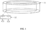
FIG. 1 is a schematic structural diagram of an electronic device according to an embodiment of the present invention. -
FIG. 2 is a schematic diagram of an annular region of a rotating member according to an embodiment of the present invention. -
FIG. 3 is a schematic flowchart of an interaction method according to an embodiment of the present invention. -
FIG. 4 is a diagram of a correspondence between infrared energy and an angle according to an embodiment of the present invention. -
FIG. 5 is a schematic flowchart of a device interaction method according to another embodiment of the present invention. -
FIG. 6 is a schematic structural diagram of an interaction device according to an embodiment of the present invention. -
FIG. 7 is a schematic structural diagram of an electronic device according to an embodiment of the present invention. - The following clearly and comprehensively describes the technical solutions in the embodiments of the present invention with reference to the accompanying drawings in the embodiments of the present invention. Apparently, the described embodiments are some embodiments of this application rather than all of the embodiments. All other embodiments obtained by a person of ordinary skill in the art based on the embodiments of the present invention shall fall within the protection scope of the present invention.
-
FIG. 1 is a schematic structural diagram of an electronic device according to an embodiment of the present invention. As shown inFIG. 1 , the electronic device includes: a rotatingmember 11 and aninfrared module 12, and the rotatingmember 11 and theinfrared module 12 are disposed opposite to each other. A surface of the rotatingmember 11 opposite to theinfrared module 12 is provided with an annular region (as shown inFIG. 2 ), areflective surface 111 is disposed on the annular region, and a width of the reflective surface gradually increases or gradually decreases along a circumferential direction of the annular region. - The
infrared module 12 includes aninfrared transmitter 121 and aninfrared receiver 122, and light emitted by theinfrared transmitter 121 is reflected by thereflective surface 111 and received by theinfrared receiver 122. During rotation of the rotatingmember 11, the light received by theinfrared receiver 122 is enhanced with an increase of a width of a portion of thereflective surface 111 directly facing theinfrared module 12. - In an embodiment, the electronic device may be a device including a rotating member, such as a watch with a rotating bezel, or a machine tool with a rotating assembly.
- For example, the electronic device is a smart watch with a rotating bezel. The rotating
member 11 includes an annular bezel rotatable relative to a base, and aninfrared module 12 is disposed on the base. A surface of the bezel opposite to the base includes a reflective surface and a non-reflective surface, the reflective surface has an excellent infrared reflection capability and the non-reflective surface has an excellent infrared absorption capability. A width of the reflective surface gradually increases or gradually decreases along a circumferential direction of the bezel, that is, the width of the reflective surface gradually increases or gradually decreases along a clockwise or counterclockwise direction. A possible situation is that, the width of the reflective surface on the bezel gradually increases along the clockwise direction, that is, an infrared reflection capability of a region on the bezel opposite to theinfrared module 12 gradually increases with the clockwise rotation of the bezel relative to the base. The light emitted by theinfrared transmitter 121 is reflected by the region on the bezel opposite to theinfrared module 12 and received by theinfrared receiver 122. During the clockwise rotation of the bezel, the strength of the light received by theinfrared receiver 122 gradually increases. It should be noted that, the width of the reflective surface may also gradually decrease along the clockwise direction, which is not limited in this embodiment of the present invention. - In an embodiment, the
reflective surface 111 is coated with a reflective layer. The reflective layer can increase the infrared absorption capability of thereflective surface 111. Optionally, the reflective layer is an infrared reflective pigment coating such as a nano-silicon dioxide coating or a nanometer titanium dioxide coating and has high infrared reflectivity. Correspondingly, a region other than thereflective surface 111 on the rotatingmember 11 may be coated with a light absorption layer, such as a carbon black coating. The reflective layer is coated on the reflective surface and the light absorption layer is coated on the region other than the reflective surface, to increase a difference in the infrared reflection capability between the reflective surface and the region other than the reflective surface. During rotation of the rotating member, the infrared module detects a large signal change rate, which is beneficial to improving the detection accuracy. - In an embodiment, the
reflective surface 111 and the region other than thereflective surface 111 have different gray scales. As shown inFIG. 2 , thereflective surface 111 is set to be white, and a region on the annular region other than thereflective surface 111 is set to be black. White and black have different gray scales and different infrared reflection capabilities. The white region has a strong infrared reflection capability, while the black region has a weak infrared reflection capability. Therefore, with the rotation of the rotating member, a width of a region of the white reflective surface relative to the infrared module gradually changes, and the strength of the signal received by the infrared module gradually changes. Relative positions of the rotatingmember 11 and theinfrared module 12 can be determined according to the strength of the signal received by the infrared module, and a rotation angle and direction of the rotatingmember 11 can be obtained. Different colors can be set to improve the difference of the infrared reflection capability between the reflective surface and the region other than the reflective surface, thereby improving the detection accuracy of the infrared receiver. - In the electronic device provided in this embodiment of the present invention, the infrared module is disposed in the electronic device, and the reflective surface whose width gradually changes along the circumferential direction is disposed on the annular region of the rotating member opposite to the infrared module. The reflection strength of infrared light reflected in the region of the rotating member opposite to the infrared module can be collected to determine the relative positions of the rotating member and the infrared module, and then determine the rotation angle and direction of the rotating member. Compared with the conventional method of adding magnets or other components that are easy to cause interference to the device and make the device vulnerable to external interference in the device, the electronic device has a simple structure and is easy to implement.
-
FIG. 3 is a schematic flowchart of an interaction method according to an embodiment of the present invention. The method is applied to the electronic device shown inFIG. 1 andFIG. 2 . The method inFIG. 3 may include the following steps. - S302. Obtain first infrared energy in a case that the infrared module is located at a first relative position of the rotating member.
- The first relative position is a position of the infrared module relative to the rotating member before the rotating member rotates.
- S304. Obtain second infrared energy in a case that the infrared module is located at a second relative position of the rotating member.
- The second relative position is a position of the infrared module relative to the rotating member after the rotating member rotates.
- S306. Determine a rotation angle and/or a rotation direction of the rotating member according to the first infrared energy and the second infrared energy.
- In the interaction method provided in this embodiment of the present invention, the infrared energy of the infrared module at different positions is obtained, and the rotation angle and/or the rotation direction of the rotating member are determined according to the infrared energy, thereby implementing device interaction, resolving the problem of poor anti-interference capability of the device during the rotation interaction, and improving the accuracy of interaction results.
- In an embodiment, when the rotation angle and/or the rotation direction of the rotating member are determined according to the first infrared energy and the second infrared energy, a first angle corresponding to the first infrared energy and a second angle corresponding to the second infrared energy can be determined according to a preset correspondence between infrared energy and an angle, and the rotation angle and the rotation direction of the rotating member can be determined according to an angle difference between the first angle and the second angle.
- In the correspondence between the infrared energy and the angle, the "angle" refers to: when the infrared module is located at a certain relative position of the rotating member, a deviation angle of the relative position in a specified direction relative to an initial rotation position of the rotating member (a center point of the rotating member is a circle point). The initial rotation position may be arbitrarily specified. For example, the initial rotation position is a position at which a smallest or largest width of a reflective surface of the infrared module on an annular region of the rotating member is obtained. The specified direction may be clockwise or counterclockwise along the circumference of the annular region.
- Based on the foregoing definition of angle, the first angle corresponding to the first infrared energy is a deviation angle of the first relative position in the specified direction relative to the initial rotation position of the rotating member, and the second angle corresponding to the second infrared energy is a deviation angle of the second relative position in the specified direction relative to the initial rotation position of the rotating member.
- The correspondence between the infrared energy and angle α is shown in
FIG. 4 . It is known that, the infrared energy corresponding to the angle of 0° is A1, and the infrared energy corresponding to the angle of 360° is A2. Then a correspondence between any infrared energy X between A1 and A2 and angle α may be represented by the following formula: α=360°× (A1-X)/(A1-A2). There is a negative correlation between the infrared energy and the angle. - In this embodiment, if the first infrared energy is greater than the second infrared energy, it can be determined from
FIG. 4 that, the first angle corresponding to the first infrared energy is less than the second angle corresponding to the second infrared energy. That is, the angle difference between the first angle and the second angle is less than 0. In this case, the rotation direction of the rotating member can be determined as a direction along which the width of the reflective surface gradually decreases. If the first infrared energy is less than the second infrared energy, the first angle corresponding to the first infrared energy is greater than the second angle corresponding to the second infrared energy. That is, the angle difference between the first angle and the second angle is greater than 0. In this case, the rotation direction of the rotating member can be determined as a direction along which the width of the reflective surface gradually increases. - Using the electronic device shown in
FIG. 2 as an example, if the first infrared energy is greater than the second infrared energy, that is, the angle difference between the first angle and the second angle is less than 0, the rotation direction of the rotating member is clockwise. If the first infrared energy is less than the second infrared energy, that is, the angle difference between the first angle and the second angle is greater than 0, the rotation direction of the rotating member is counterclockwise. - In this embodiment, the rotation angle and the rotation direction of the rotating member can be determined according to the first infrared energy and the second infrared energy, so that the determining method of the rotation angle and the rotation direction of the rotating member is simple and fast. In addition, the infrared energy is received by the infrared module and the infrared module does not cause interference to the electronic device. Therefore, compared with the conventional method, the accuracy of the determined results of the rotation angle and the rotation direction of the rotating member is improved.
- In an embodiment, a first interaction instruction corresponding to the rotation angle and/or the rotation direction of the rotating member can be determined according to a preset correspondence between a rotation angle and/or a rotation direction and a device interaction instruction.
- The device interaction instruction may be a page turning instruction, an adjustment instruction, or the like. The first interaction instruction is used to instruct the electronic device to perform an operation corresponding to the first interaction instruction.
- For example, the page turning instruction is executed by rotating in the direction along which the width of the reflective surface gradually increases, and it is preset that, every 30° of rotation corresponds to turning one page backward. When the rotation direction is the direction along which the width of the reflective surface gradually increases and the rotation angle is 120°, it can be determined that, the first interaction instruction is to turn four pages backward.
- Using the foregoing example, it is assumed that a display interface of a watch with a rotating bezel includes 5 display pages, there are 5 function options of "call", "location", "settings", "sports", and "health" in sequence, and a current display interface is the "location" function option. When the rotation direction is the direction along which the width of the reflective surface gradually increases and the rotation angle is 60°, it is determined to turn 2 function options backward, that is, turn to the display page of the "sports" function option.
- In this embodiment, the first interaction instruction corresponding to the rotation angle and/or the rotation direction of the rotating member can be determined according to the preset correspondence between the rotation angle and/or the rotation direction and the device interaction instruction. In addition, the operation corresponding to the first interaction instruction is performed, that is, the corresponding interaction instruction can be determined through the rotation angle and/or the rotation direction of the electronic device, thereby implementing the rotation interaction and improving the rotation interaction experience of a user.
-
FIG. 5 is a schematic flowchart of an interaction method according to another embodiment of the present invention. In this embodiment, the interaction method is applied to a watch provided with a rotating bezel and an infrared module. A structure of the watch is shown inFIG. 1 andFIG. 2 , and the method inFIG. 5 may include the following steps. - S501. Obtain second infrared energy in a case that the infrared module is located at a second relative position of the rotating bezel.
- The first relative position is a position of the infrared module relative to the rotating bezel before the rotating bezel rotates.
- S502. Obtain second infrared energy in a case that the infrared module is located at a second relative position of the rotating bezel.
- The second relative position is a position of the infrared module relative to the rotating bezel after the rotating bezel rotates.
- S503. Determine a first angle corresponding to the first infrared energy and a second angle corresponding to the second infrared energy according to a preset correspondence between infrared energy and an angle.
- In the correspondence between the infrared energy and the angle, the "angle" refers to: when the infrared module is located at a certain relative position of the rotating bezel, a deviation angle of the relative position in a specified direction relative to an initial rotation position of the rotating bezel (a center point of the rotating bezel is a circle point). The initial rotation position may be arbitrarily specified. For example, the initial rotation position is a position at which a smallest or largest width of a reflective surface of the infrared module on an annular region of the rotating bezel is obtained. The specified direction may be clockwise or counterclockwise along the circumference of the annular region.
- Based on the foregoing definition of angle, the first angle corresponding to the first infrared energy is a deviation angle of the first relative position in the specified direction relative to the initial rotation position of the rotating bezel, and the second angle corresponding to the second infrared energy is a deviation angle of the second relative position in the specified direction relative to the initial rotation position of the rotating bezel.
- The correspondence between the infrared energy and angle α is shown in
FIG. 4 . It is known that, the infrared energy corresponding to the angle of 0° is Al, and the infrared energy corresponding to the angle of 360° is A2. Then a correspondence between any infrared energy X between A1 and A2 and angle α may be represented by the following formula: α=360°× (A1-X)/(A1-A2). There is a negative correlation between the infrared energy and the angle. - S504. Determine a rotation angle and/or a rotation direction of the rotating bezel according to an angle difference between the first angle and the second angle.
- In this embodiment, if the first infrared energy is greater than the second infrared energy, it can be determined from
FIG. 4 that, the first angle corresponding to the first infrared energy is less than the second angle corresponding to the second infrared energy. That is, the angle difference between the first angle and the second angle is less than 0. In this case, the rotation direction of the rotating bezel can be determined as a direction along which the width of the reflective surface gradually decreases. If the first infrared energy is less than the second infrared energy, the first angle corresponding to the first infrared energy is greater than the second angle corresponding to the second infrared energy. That is, the angle difference between the first angle and the second angle is greater than 0. In this case, the rotation direction of the rotating bezel can be determined as a direction along which the width of the reflective surface gradually increases. - S505. Determine a first interaction instruction corresponding to the rotation angle and/or the rotation direction of the rotating bezel according to a preset correspondence between a rotation angle and/or a rotation direction and a device interaction instruction.
- The first interaction instruction is used to instruct the watch to perform an operation corresponding to the first interaction instruction.
- For example, a page turning instruction is executed by rotating in the direction along which the width of the reflective surface gradually increases, and it is preset that, every 30° of rotation corresponds to turning one page backward. It is assumed that, a display interface of the watch includes 5 display pages, there are 5 function options of "call", "location", "settings", "sports", and "health" in sequence, and a current display interface is the "location" function option. When the rotation direction is the direction along which the width of the reflective surface gradually increases and the rotation angle is 60°, it is determined to turn 2 function options backward, that is, turn to the display page of the "sports" function option.
- In the interaction method applied to the watch provided in this embodiment of the present invention, the infrared energy of the infrared module at different positions is obtained, and the rotation angle and/or the rotation direction of the rotating bezel are determined according to the infrared energy, thereby implementing device interaction, resolving the problem of poor anti-interference capability of the watch during the rotation interaction, and improving the accuracy of interaction results.
-
FIG. 6 is a schematic structural diagram of an interaction device according to an embodiment of the present invention. Referring toFIG. 6 , the interaction device includes: a first obtainingmodule 610, configured to obtain first infrared energy in a case that an infrared module is located at a first relative position of a rotating member; a second obtainingmodule 620, configured to obtain second infrared energy in a case that the infrared module is located at a second relative position of the rotating member; and a first determiningmodule 630, configured to determine a rotation angle and/or a rotation direction of the rotating member according to the first infrared energy and the second infrared energy. The first relative position is a position of the infrared module relative to the rotating member before the rotating member rotates, and the second relative position is a position of the infrared module relative to the rotating member after the rotating member rotates. - In an embodiment, the first determining
module 630 includes: a first determining unit, configured to determine a first angle corresponding to the first infrared energy and a second angle corresponding to the second infrared energy according to a preset correspondence between infrared energy and an angle, where the first angle is a deviation angle of the first relative position in a specified direction relative to an initial rotation position of the rotating member; and the second angle is a deviation angle of the second relative position in a specified direction relative to an initial rotation position of the rotating member; and a second determining unit, configured to determine the rotation angle and/or the rotation direction of the rotating member according to an angle difference between the first angle and the second angle. - In an embodiment, the interaction device further includes: a second determining module, configured to determine a first interaction instruction corresponding to the rotation angle and/or the rotation direction of the rotating member according to a preset correspondence between a rotation angle and/or a rotation direction and a device interaction instruction. The first interaction instruction is used to instruct an electronic device to perform an operation corresponding to the first interaction instruction.
- The interaction device provided in this embodiment of the present invention can implement processes of the interaction method in the foregoing method embodiment. To avoid repetition, details are not described herein again.
- The interaction device applied to the interaction method provided in this embodiment of the present invention obtains the infrared energy of the infrared module at different positions, and determines the rotation angle and/or the rotation direction of the rotating member according to the infrared energy, thereby implementing device interaction, resolving the problem of poor anti-interference capability of the device during the rotation interaction, and improving the accuracy of interaction results.
- Specific embodiments of this specification are described above. Other embodiments fall within the scope of the appended claims. In some cases, the actions or steps recorded in the claims may be performed in sequences different from those in the embodiments and an expected result may still be achieved. In addition, the processes depicted in the accompanying drawings do not necessarily require the particular order shown or sequential order to achieve the expected results. In some implementations, multitasking and parallel processing may be feasible or beneficial.
-
FIG. 7 is a schematic structural diagram of an electronic device according to an embodiment of the present invention. Theelectronic device 700 includes, but is not limited to: a component such as aradio frequency unit 701, anetwork module 702, anaudio output unit 703, aninput unit 704, asensor 705, adisplay unit 706, auser input unit 707, aninterface unit 708, amemory 709, aprocessor 710, apower supply 711. A person skilled in the art may understand that, the electronic device structure shown inFIG. 7 does not constitute a limitation to the electronic device. The electronic device may include more or fewer components than those shown in the figure, may combine some components, or may have different component arrangements. In this embodiment of the present invention, the electronic device includes, but is not limited to a mobile phone, a tablet computer, a laptop computer, a palmtop computer, an in-vehicle terminal, a wearable device, a pedometer, and the like. - The
processor 710 is configured to obtain first infrared energy in a case that an infrared module is located at a first relative position of a rotating member; obtain second infrared energy in a case that the infrared module is located at a second relative position of the rotating member; and determine a rotation angle and/or a rotation direction of the rotating member according to the first infrared energy and the second infrared energy. The first relative position is a position of the infrared module relative to the rotating member before the rotating member rotates, and the second relative position is a position of the infrared module relative to the rotating member after the rotating member rotates. - The electronic device applied to the interaction method provided in this embodiment of the present invention obtains the infrared energy of the infrared module at different positions, and determines the rotation angle and/or the rotation direction of the rotating member according to the infrared energy, thereby implementing device interaction, resolving the problem of poor anti-interference capability of the device during the rotation interaction, and improving the accuracy of interaction results.
- It should be understood that, in this embodiment of the present invention, the
radio frequency unit 701 may be configured to receive and transmit signals in a process of receiving and transmitting information or calls, specifically, to receive downlink data from a base station, then transmit the downlink data to theprocessor 710 for processing; and additionally, transmit uplink data to the base station. Generally, theradio frequency unit 701 includes, but is not limited to, an antenna, at least one amplifier, a transceiver, a coupler, a low noise amplifier, a duplexer, and the like. In addition, theradio frequency unit 701 may further communicate with a network and another device through a wireless communication system. - The electronic device provides wireless broadband Internet access for a user through the
network module 702, such as helps the user to receive and send an email, browse a web page, access streaming media, and the like. - The
audio output unit 703 may convert audio data received by theradio frequency unit 701 and thenetwork module 702 or stored in thememory 709 into an audio signal and output the audio signal as sound. Moreover, theaudio output unit 703 may provide an audio output (such as call signal receiving sound or message receiving sound) that is related to a particular function executed by theelectronic device 700. Theaudio output unit 703 includes a speaker, a buzzer, a receiver, and the like. - The
input unit 704 is configured to receive an audio signal or a video signal. Theinput unit 704 may include a graphics processing unit (Graphics Processing Unit, GPU) 7041 and amicrophone 7042. Thegraphics processing unit 7041 processes image data of a static picture or a video that is obtained by an image acquisition device (such as a camera) in a video acquisition mode or an image acquisition mode. A processed image frame may be displayed on thedisplay unit 706. The image frame processed by thegraphics processing unit 7041 may be stored in the memory 709 (or other storage media) or transmitted via theradio frequency unit 701 or thenetwork module 702. Themicrophone 7042 may receive sound and can process the sound into audio data. The processed audio data may be converted, in a phone talk mode, into a format that can be sent to a mobile communication base station via theradio frequency unit 701 to output. - The
electronic device 700 further includes at least onesensor 705, such as an optical sensor, a motion sensor, and other sensors. Specifically, the optical sensor includes an ambient light sensor and a proximity sensor. The ambient light sensor may adjust luminance of thedisplay panel 7061 according to brightness of the ambient light. The proximity sensor may switch off thedisplay panel 7061 and/or backlight when theelectronic device 700 is moved to the ear. As one type of the motion sensor, an acceleration sensor may detect magnitude of accelerations in various directions (generally on three axes), and may detect a magnitude and a direction of gravity when static, which may be configured to recognize an attitude of the electronic device (such as horizontal and vertical screen switching, a related game, and magnetometer attitude calibration), a function related to vibration recognition (such as a pedometer and a knock), and the like; thesensor 705 may further include other sensors such as a fingerprint sensor, a pressure sensor, an iris sensor, a molecular sensor, a gyroscope, a barometer, a hygrometer, a thermometer, and an infrared sensor. Details are not described herein. - The
display unit 706 is configured to display information input by the user or information provided for the user. Thedisplay unit 706 may include adisplay panel 7061. Thedisplay panel 7061 may be configured by using a liquid crystal display (Liquid Crystal Display, LCD), an organic light-emitting diode (Organic Light-Emitting Diode, OLED), or the like. - A
user input unit 707 may be configured to receive input numeral or character information, and generate a key signal input related to a user setting and function control of the electronic device. Specifically, theuser input unit 707 includes atouch panel 7071 and anotherinput device 7072. Thetouch panel 7071, also referred to as a touchscreen, may collect a touch operation of a user on or near the touch panel (such as an operation of a user on or near thetouch panel 7071 by using any suitable object or attachment, such as a finger or a touch pen). Thetouch panel 7071 may include two parts: a touch detection device and a touch controller. The touch detection device detects a touch orientation of the user, detects a signal brought by the touch operation, and transmits the signal to the touch controller. The touch controller receives touch information from the touch detection device, converts the touch information into a contact coordinate, then transmits the contact coordinate to theprocessor 710, receives and executes a command transmitted by theprocessor 710. In addition, thetouch panel 7071 may be implemented by using various types, such as a resistive type, a capacitance type, an infrared type, and a surface acoustic wave type. In addition to thetouch panel 7071, theuser input unit 707 may further include the anotherinput device 7072. Specifically, the anotherinput device 7072 may include, but not limited to a physical keyboard, a functional key (such as a volume control key or a switch key), a track ball, a mouse, and a joystick, and details are not described herein. - Further, the
touch panel 7071 may cover thedisplay panel 7061. After detecting a touch operation on or near the touch panel, thetouch panel 7071 transfers the touch operation to theprocessor 710, to determine a type of a touch event. Then, theprocessor 710 provides a corresponding visual output on thedisplay panel 7061 according to the type of the touch event. InFIG. 7 , thetouch panel 7071 and thedisplay panel 7061 implement, as two independent parts, input and output functions of the electronic device. However, in some embodiments, thetouch panel 7071 and thedisplay panel 7061 may be integrated to implement the input and output functions of the electronic device, and is not specifically limited herein. - The
interface unit 708 is an interface through which an external device and theelectronic device 700 are connected. For example, the external device may include a wired or wireless headset port, an external power supply (or a battery charger) port, a wired or wireless data port, a storage card port, a port used to connect an device having an identification module, an audio input/output (I/O) port, a video I/O port, an earphone port, and the like. Theinterface unit 708 may be configured to receive an input (for example, data information or power) from an external device, and transmit the received input to one or more elements in theelectronic device 700, or may be configured to transmit data between theelectronic device 700 and the external device. - The
memory 709 may be configured to store a software program and various data. Thememory 709 may mainly include a program storage area and a data storage area. The program storage area may store an operating system, an application program required by at least one function (for example, a sound playback function and an image playback function), or the like; The data storage area may store data (for example, audio data and a phone book) created according to use of the mobile phone. In addition, thememory 709 may include a high speed random access memory, and may further include a non-volatile memory, such as at least one magnetic disk storage device, a flash storage device or other non-volatile solid state storage devices. - The
processor 710 is a control center of the electronic device, and connects various parts of the entire electronic device by using various interfaces and lines. By running or executing the software program and/or module stored in thememory 709, and invoking data stored in thememory 709, the processor performs various functions of the electronic device and processes data, thereby performing overall monitoring on the electronic device. Theprocessor 710 may include one or more processing units; Exemplarily, theprocessor 710 may integrate an application processor and a modem. The application processor mainly processes an operating system, a user interface, an application program, and the like. The modem mainly processes wireless communication. It may be understood that, the modem processor may alternatively not be integrated in theprocessor 710. - The
electronic device 700 may further include thepower supply 711 for supplying power to the components (such as a battery). Exemplarily, thepower supply 711 may be logically connected to theprocessor 710 by using a power management system, thereby implementing functions such as charging, discharging, and power consumption management by using the power management system. - In addition, the
electronic device 700 includes some unshown functional modules, and details are not described herein. - Exemplarily, an embodiment of the present invention further provides an electronic device, including a
processor 710, amemory 709, and a computer program stored in thememory 709 and executable on theprocessor 710. The computer program, when executed by theprocessor 710, implements processes of the above described interaction method embodiment and can achieve the same technical effect. To avoid repetition, details are not described herein again. - An embodiment of the present invention further provides a computer-readable storage medium, storing a computer program. The computer program, when executed by a processor, implements processes of the above described interaction method embodiment and can achieve the same technical effect. To avoid repetition, details are not described herein again. The computer-readable storage medium may be a read-only memory (Read-Only Memory, ROM), a random access memory (Random Access Memory, RAM), a magnetic disk, an optical disc, or the like.
- It should be noted that, in this specification, terms "comprise", "include", and any variants thereof are intended to cover a non-exclusive inclusion. Therefore, in the context of a process, method, object, or device that includes a series of elements, the process, method, object, or device not only includes such elements, but also includes other elements not specified expressly, or may include inherent elements of the process, method, object, or device. Without more limitations, elements defined by the sentence "comprising one" does not exclude that there are still other same elements in the processes, methods, objects, or devices.
- Through the foregoing description on the implementations, a person skilled in the art can clearly learn that the foregoing embodiment methods may be implemented by using software in combination with a necessary universal hardware platform. Certainly, the embodiment methods may also be implemented by using hardware, but the former is a better implementation in many cases. Based on such an understanding, the technical solutions of the present invention essentially or the part contributing to the existing technologies may be implemented in the form of a software product. The computer software product is stored in a storage medium (for example, a ROM/RAM, a magnetic disk or an optical disc), and includes several instructions for instructing a terminal (which may be a mobile phone, a computer, a server, an air conditioner, a network device, or the like) to perform the method described in the embodiments of the present invention.
- The embodiments of the present invention are described above with reference to the accompanying drawings, but the present invention is not limited to the above specific embodiments, and the above specific embodiments are merely exemplary and not limited. A person of ordinary skill in the art may make many forms in enlightenment of the present invention without departing from the principle and protection scope of the present invention, and the forms shall fall within the protection scope of the present invention.
Claims (11)
- An electronic device, comprising a rotating member and an infrared module, wherein the rotating member and the infrared module are disposed opposite to each other;a surface of the rotating member opposite to the infrared module is provided with an annular region, a reflective surface is disposed on the annular region, and a width of the reflective surface gradually increases or gradually decreases along a circumferential direction of the annular region;the infrared module comprises an infrared transmitter and an infrared receiver, and light emitted by the infrared transmitter is reflected by the reflective surface and then received by the infrared receiver, whereinduring rotation of the rotating member, the light received by the infrared receiver is enhanced with an increase of a width of a portion of the reflective surface directly facing the infrared module.
- The electronic device according to claim 1, wherein the reflective surface is coated with a reflective layer.
- The electronic device according to claim 1, wherein the reflective surface is coated white.
- An interaction method, applied to the electronic device according to any one of claims 1 to 3, comprising:obtaining first infrared energy in a case that the infrared module is located at a first relative position of the rotating member;obtaining second infrared energy in a case that the infrared module is located at a second relative position of the rotating member; anddetermining a rotation angle and/or a rotation direction of the rotating member according to the first infrared energy and the second infrared energy;wherein the first relative position is a position of the infrared module relative to the rotating member before the rotating member rotates, and the second relative position is a position of the infrared module relative to the rotating member after the rotating member rotates.
- The method according to claim 4, wherein the determining a rotation angle and/or a rotation direction of the rotating member according to the first infrared energy and the second infrared energy comprises:determining a first angle corresponding to the first infrared energy and a second angle corresponding to the second infrared energy, according to a preset correspondence between infrared energy and an angle,wherein the first angle is a deviation angle of the first relative position in a specified direction relative to an initial rotation position of the rotating member; and the second angle is a deviation angle of the second relative position in a specified direction relative to an initial rotation position of the rotating member; anddetermining the rotation angle and/or the rotation direction of the rotating member according to an angle difference between the first angle and the second angle.
- The method according to claim 4, further comprising:
determining a first interaction instruction corresponding to the rotation angle and/or the rotation direction of the rotating member according to a preset correspondence between a rotation angle and/or a rotation direction and a device interaction instruction, wherein the first interaction instruction is used to instruct the electronic device to perform an operation corresponding to the first interaction instruction. - An interaction device, comprising:a first obtaining module, configured to obtain first infrared energy in a case that an infrared module is located at a first relative position of a rotating member;a second obtaining module, configured to obtain second infrared energy in a case that the infrared module is located at a second relative position of the rotating member; anda first determining module, configured to determine a rotation angle and/or a rotation direction of the rotating member according to the first infrared energy and the second infrared energy;wherein the first relative position is a position of the infrared module relative to the rotating member before the rotating member rotates, and the second relative position is a position of the infrared module relative to the rotating member after the rotating member rotates.
- The device according to claim 7, wherein the first determining module comprises:a first determining unit, configured to determine a first angle corresponding to the first infrared energy and a second angle corresponding to the second infrared energy, according to a preset correspondence between infrared energy and an angle, wherein the first angle is a deviation angle of the first relative position in a specified direction relative to an initial rotation position of the rotating member; and the second angle is a deviation angle of the second relative position in a specified direction relative to an initial rotation position of the rotating member; anda second determining unit, configured to determine a rotation angle and/or a rotation direction of the rotating member according to an angle difference between the first angle and the second angle.
- The device according to claim 7, further comprising:
a second determining module, configured to determine a first interaction instruction corresponding to the rotation angle and/or the rotation direction of the rotating member according to a preset correspondence between a rotation angle and/or a rotation direction and a device interaction instruction, wherein the first interaction instruction is used to instruct an electronic device to perform an operation corresponding to the first interaction instruction. - An electronic device, comprising:a memory, storing computer program instructions; anda processor, implementing the interaction method according to any one of claims 4 to 6 when the computer program instructions are executed by the processor.
- A computer-readable storage medium, storing a computer program, wherein when the computer program is executed by a processor, steps of the interaction method according to any one of claims 4 to 6 are implemented.
Applications Claiming Priority (2)
| Application Number | Priority Date | Filing Date | Title |
|---|---|---|---|
| CN202010261292.XA CN111552166B (en) | 2020-04-03 | 2020-04-03 | Electronic equipment, interaction method and device |
| PCT/CN2021/075753 WO2021196894A1 (en) | 2020-04-03 | 2021-02-07 | Electronic device, and interaction method and apparatus |
Publications (2)
| Publication Number | Publication Date |
|---|---|
| EP4120030A1 true EP4120030A1 (en) | 2023-01-18 |
| EP4120030A4 EP4120030A4 (en) | 2023-09-06 |
Family
ID=72007352
Family Applications (1)
| Application Number | Title | Priority Date | Filing Date |
|---|---|---|---|
| EP21780676.9A Pending EP4120030A4 (en) | 2020-04-03 | 2021-02-07 | Electronic device, and interaction method and apparatus |
Country Status (5)
| Country | Link |
|---|---|
| US (1) | US12313787B2 (en) |
| EP (1) | EP4120030A4 (en) |
| JP (1) | JP7508577B2 (en) |
| CN (1) | CN111552166B (en) |
| WO (1) | WO2021196894A1 (en) |
Families Citing this family (3)
| Publication number | Priority date | Publication date | Assignee | Title |
|---|---|---|---|---|
| CN111552166B (en) * | 2020-04-03 | 2021-05-25 | 维沃移动通信有限公司 | Electronic equipment, interaction method and device |
| CN114355756A (en) * | 2021-12-30 | 2022-04-15 | 歌尔科技有限公司 | An electronic device and a control method for the electronic device |
| CN115632646A (en) * | 2022-09-26 | 2023-01-20 | Oppo广东移动通信有限公司 | Switch assembly, electronic device and switch state detection method |
Family Cites Families (25)
| Publication number | Priority date | Publication date | Assignee | Title |
|---|---|---|---|---|
| US4327362A (en) * | 1978-10-23 | 1982-04-27 | Rockwell International Corporation | Meter rotor rotation optical sensor |
| JPH0743134A (en) * | 1993-07-30 | 1995-02-10 | Optec Dai Ichi Denko Co Ltd | Rotation angle detector |
| JPH0787393A (en) * | 1993-09-13 | 1995-03-31 | Fujitsu Ltd | Infrared imaging device |
| JP3627531B2 (en) * | 1998-09-30 | 2005-03-09 | セイコーエプソン株式会社 | Information processing device |
| US6020967A (en) * | 1999-03-31 | 2000-02-01 | Gregorio; Pedro | Differential displacement optical sensor |
| DE602004020883D1 (en) * | 2004-07-22 | 2009-06-10 | Bea Sa | Thermo-sensitive device for detecting the presence of automatic doors |
| JP2006106240A (en) * | 2004-10-04 | 2006-04-20 | Sharp Corp | Rotational speed detection circuit and projection display device using the circuit |
| US7304295B2 (en) * | 2005-09-30 | 2007-12-04 | Avago Technologies Ecbuip (Singapore) Pte Ltd | Method and system of detecting eccentricity and up/down movement of a code wheel of an optical encoder set |
| JP2007266344A (en) * | 2006-03-29 | 2007-10-11 | Dainippon Screen Mfg Co Ltd | Position detection sensor, motor, and substrate processing apparatus |
| KR101589743B1 (en) * | 2008-11-07 | 2016-01-28 | 삼성전자주식회사 | Apparatus for wheel running and portable electronic device having the same |
| KR20130038847A (en) * | 2010-03-23 | 2013-04-18 | 가부시키가이샤 아사히 러버 | Silicone resin reflective substrate, manufacturing method for same, and base material composition used in reflective substrate |
| CN101982736A (en) * | 2010-10-28 | 2011-03-02 | 朱孝立 | Code disk of electro-optic rotary encoder |
| US11175747B2 (en) * | 2013-02-04 | 2021-11-16 | Pixart Imaging Inc. | Optical processing apparatus and operating method thereof |
| JP2015111772A (en) * | 2013-12-06 | 2015-06-18 | シチズンホールディングス株式会社 | Projection device |
| JP6341720B2 (en) * | 2014-03-27 | 2018-06-13 | 日本電産コパル株式会社 | Tape feeder and method for controlling the tape feeder |
| WO2017126727A1 (en) * | 2016-01-22 | 2017-07-27 | 엘지전자 주식회사 | Watch-type mobile terminal and method of operation thereof |
| JP2018189477A (en) * | 2017-05-02 | 2018-11-29 | セイコーエプソン株式会社 | Wearable device and display method |
| US10203662B1 (en) * | 2017-09-25 | 2019-02-12 | Apple Inc. | Optical position sensor for a crown |
| CN207976717U (en) * | 2018-01-10 | 2018-10-16 | 何屹 | 360 degree rotation images wrist-watch |
| CN108592827B (en) * | 2018-06-28 | 2024-06-18 | 福湫科技(深圳)有限公司 | Precise angle measurement sensor and measurement method thereof |
| CN109257466B (en) * | 2018-10-18 | 2021-01-08 | 维沃移动通信有限公司 | Mobile terminal and control method of mobile terminal |
| CN109861757B (en) * | 2019-03-26 | 2021-03-09 | Oppo广东移动通信有限公司 | Control method, time-of-flight assembly, electronic device, and readable storage medium |
| CN209461483U (en) * | 2019-04-15 | 2019-10-01 | 扬州乾照光电有限公司 | An infrared LED chip with a reflective bowl |
| CN110332950B (en) | 2019-06-26 | 2026-02-06 | 维沃移动通信有限公司 | Infrared sensing module, terminal equipment, control method and control device of terminal equipment |
| CN111552166B (en) * | 2020-04-03 | 2021-05-25 | 维沃移动通信有限公司 | Electronic equipment, interaction method and device |
-
2020
- 2020-04-03 CN CN202010261292.XA patent/CN111552166B/en active Active
-
2021
- 2021-02-07 JP JP2022559469A patent/JP7508577B2/en active Active
- 2021-02-07 WO PCT/CN2021/075753 patent/WO2021196894A1/en not_active Ceased
- 2021-02-07 EP EP21780676.9A patent/EP4120030A4/en active Pending
-
2022
- 2022-09-28 US US17/954,405 patent/US12313787B2/en active Active
Also Published As
| Publication number | Publication date |
|---|---|
| US12313787B2 (en) | 2025-05-27 |
| WO2021196894A1 (en) | 2021-10-07 |
| JP7508577B2 (en) | 2024-07-01 |
| EP4120030A4 (en) | 2023-09-06 |
| CN111552166B (en) | 2021-05-25 |
| JP2023519403A (en) | 2023-05-10 |
| CN111552166A (en) | 2020-08-18 |
| US20230019967A1 (en) | 2023-01-19 |
Similar Documents
| Publication | Publication Date | Title |
|---|---|---|
| US11392226B2 (en) | Active stylus calibration method, active stylus, and electronic device | |
| US20210027037A1 (en) | Fingerprint recognition method and mobile terminal | |
| EP3702895B1 (en) | Notification message prompting method and mobile terminal | |
| US12313787B2 (en) | Electronic device, and interaction method and device | |
| EP3829148A1 (en) | Object identification method and mobile terminal | |
| US11625164B2 (en) | Display method and terminal device | |
| AU2020263183B2 (en) | Parameter Obtaining Method and Terminal Device | |
| US11431401B2 (en) | Terminal detection method and terminal | |
| CN110730298A (en) | A display control method and electronic device | |
| US20220393506A1 (en) | Circuit control apparatus and method | |
| CN109857495A (en) | A display control method and terminal device | |
| WO2021136495A1 (en) | Method and apparatus for controlling page layout of on-board unit display interface | |
| CN108089801A (en) | A kind of method for information display and mobile terminal | |
| US20220360709A1 (en) | Mobile terminal, shooting mode detection method, and storage medium | |
| CN110058686B (en) | Control method and terminal equipment | |
| EP4016269A1 (en) | Icon display method and terminal | |
| CN110824516B (en) | Positioning method and electronic equipment | |
| CN111356221A (en) | Method for adjusting transmitting power and electronic equipment | |
| CN111142772A (en) | Content display method and wearable device | |
| CN110427124B (en) | Projection device, wearable device and detection control method | |
| CN109947617B (en) | Method, terminal and readable storage medium for monitoring display content of application interface | |
| CN109828703B (en) | Content selection method and terminal equipment | |
| CN108107422B (en) | A kind of method for determining speed and mobile terminal of Moving Objects | |
| US11800545B2 (en) | Control method and terminal | |
| KR20210016041A (en) | PH calculation method and terminal |
Legal Events
| Date | Code | Title | Description |
|---|---|---|---|
| STAA | Information on the status of an ep patent application or granted ep patent |
Free format text: STATUS: THE INTERNATIONAL PUBLICATION HAS BEEN MADE |
|
| PUAI | Public reference made under article 153(3) epc to a published international application that has entered the european phase |
Free format text: ORIGINAL CODE: 0009012 |
|
| STAA | Information on the status of an ep patent application or granted ep patent |
Free format text: STATUS: REQUEST FOR EXAMINATION WAS MADE |
|
| 17P | Request for examination filed |
Effective date: 20221012 |
|
| AK | Designated contracting states |
Kind code of ref document: A1 Designated state(s): AL AT BE BG CH CY CZ DE DK EE ES FI FR GB GR HR HU IE IS IT LI LT LU LV MC MK MT NL NO PL PT RO RS SE SI SK SM TR |
|
| DAV | Request for validation of the european patent (deleted) | ||
| DAX | Request for extension of the european patent (deleted) | ||
| A4 | Supplementary search report drawn up and despatched |
Effective date: 20230804 |
|
| RIC1 | Information provided on ipc code assigned before grant |
Ipc: G01D 5/347 20060101ALI20230731BHEP Ipc: G01D 5/32 20060101ALI20230731BHEP Ipc: G01P 13/02 20060101ALI20230731BHEP Ipc: G01B 11/26 20060101ALI20230731BHEP Ipc: G06F 3/01 20060101ALI20230731BHEP Ipc: G04B 39/00 20060101AFI20230731BHEP |
|
| STAA | Information on the status of an ep patent application or granted ep patent |
Free format text: STATUS: EXAMINATION IS IN PROGRESS |
|
| 17Q | First examination report despatched |
Effective date: 20250424 |
|
| GRAP | Despatch of communication of intention to grant a patent |
Free format text: ORIGINAL CODE: EPIDOSNIGR1 |
|
| STAA | Information on the status of an ep patent application or granted ep patent |
Free format text: STATUS: GRANT OF PATENT IS INTENDED |
|
| INTG | Intention to grant announced |
Effective date: 20260323 |